EP3751841A1 - Multi-region backlight control system and method, television, and readable storage medium - Google Patents
Multi-region backlight control system and method, television, and readable storage medium Download PDFInfo
- Publication number
- EP3751841A1 EP3751841A1 EP18926026.8A EP18926026A EP3751841A1 EP 3751841 A1 EP3751841 A1 EP 3751841A1 EP 18926026 A EP18926026 A EP 18926026A EP 3751841 A1 EP3751841 A1 EP 3751841A1
- Authority
- EP
- European Patent Office
- Prior art keywords
- signal
- driver
- liquid crystal
- crystal display
- display screen
- Prior art date
- Legal status (The legal status is an assumption and is not a legal conclusion. Google has not performed a legal analysis and makes no representation as to the accuracy of the status listed.)
- Granted
Links
Images


Classifications
-
- G—PHYSICS
- G09—EDUCATION; CRYPTOGRAPHY; DISPLAY; ADVERTISING; SEALS
- G09G—ARRANGEMENTS OR CIRCUITS FOR CONTROL OF INDICATING DEVICES USING STATIC MEANS TO PRESENT VARIABLE INFORMATION
- G09G3/00—Control arrangements or circuits, of interest only in connection with visual indicators other than cathode-ray tubes
- G09G3/20—Control arrangements or circuits, of interest only in connection with visual indicators other than cathode-ray tubes for presentation of an assembly of a number of characters, e.g. a page, by composing the assembly by combination of individual elements arranged in a matrix no fixed position being assigned to or needed to be assigned to the individual characters or partial characters
- G09G3/34—Control arrangements or circuits, of interest only in connection with visual indicators other than cathode-ray tubes for presentation of an assembly of a number of characters, e.g. a page, by composing the assembly by combination of individual elements arranged in a matrix no fixed position being assigned to or needed to be assigned to the individual characters or partial characters by control of light from an independent source
- G09G3/3406—Control of illumination source
- G09G3/342—Control of illumination source using several illumination sources separately controlled corresponding to different display panel areas, e.g. along one dimension such as lines
-
- H—ELECTRICITY
- H04—ELECTRIC COMMUNICATION TECHNIQUE
- H04N—PICTORIAL COMMUNICATION, e.g. TELEVISION
- H04N5/00—Details of television systems
- H04N5/44—Receiver circuitry for the reception of television signals according to analogue transmission standards
-
- G—PHYSICS
- G09—EDUCATION; CRYPTOGRAPHY; DISPLAY; ADVERTISING; SEALS
- G09G—ARRANGEMENTS OR CIRCUITS FOR CONTROL OF INDICATING DEVICES USING STATIC MEANS TO PRESENT VARIABLE INFORMATION
- G09G3/00—Control arrangements or circuits, of interest only in connection with visual indicators other than cathode-ray tubes
- G09G3/20—Control arrangements or circuits, of interest only in connection with visual indicators other than cathode-ray tubes for presentation of an assembly of a number of characters, e.g. a page, by composing the assembly by combination of individual elements arranged in a matrix no fixed position being assigned to or needed to be assigned to the individual characters or partial characters
- G09G3/34—Control arrangements or circuits, of interest only in connection with visual indicators other than cathode-ray tubes for presentation of an assembly of a number of characters, e.g. a page, by composing the assembly by combination of individual elements arranged in a matrix no fixed position being assigned to or needed to be assigned to the individual characters or partial characters by control of light from an independent source
- G09G3/3406—Control of illumination source
- G09G3/342—Control of illumination source using several illumination sources separately controlled corresponding to different display panel areas, e.g. along one dimension such as lines
- G09G3/3426—Control of illumination source using several illumination sources separately controlled corresponding to different display panel areas, e.g. along one dimension such as lines the different display panel areas being distributed in two dimensions, e.g. matrix
-
- G—PHYSICS
- G09—EDUCATION; CRYPTOGRAPHY; DISPLAY; ADVERTISING; SEALS
- G09G—ARRANGEMENTS OR CIRCUITS FOR CONTROL OF INDICATING DEVICES USING STATIC MEANS TO PRESENT VARIABLE INFORMATION
- G09G3/00—Control arrangements or circuits, of interest only in connection with visual indicators other than cathode-ray tubes
- G09G3/20—Control arrangements or circuits, of interest only in connection with visual indicators other than cathode-ray tubes for presentation of an assembly of a number of characters, e.g. a page, by composing the assembly by combination of individual elements arranged in a matrix no fixed position being assigned to or needed to be assigned to the individual characters or partial characters
- G09G3/34—Control arrangements or circuits, of interest only in connection with visual indicators other than cathode-ray tubes for presentation of an assembly of a number of characters, e.g. a page, by composing the assembly by combination of individual elements arranged in a matrix no fixed position being assigned to or needed to be assigned to the individual characters or partial characters by control of light from an independent source
- G09G3/3406—Control of illumination source
- G09G3/3413—Details of control of colour illumination sources
-
- G—PHYSICS
- G09—EDUCATION; CRYPTOGRAPHY; DISPLAY; ADVERTISING; SEALS
- G09G—ARRANGEMENTS OR CIRCUITS FOR CONTROL OF INDICATING DEVICES USING STATIC MEANS TO PRESENT VARIABLE INFORMATION
- G09G3/00—Control arrangements or circuits, of interest only in connection with visual indicators other than cathode-ray tubes
- G09G3/20—Control arrangements or circuits, of interest only in connection with visual indicators other than cathode-ray tubes for presentation of an assembly of a number of characters, e.g. a page, by composing the assembly by combination of individual elements arranged in a matrix no fixed position being assigned to or needed to be assigned to the individual characters or partial characters
- G09G3/34—Control arrangements or circuits, of interest only in connection with visual indicators other than cathode-ray tubes for presentation of an assembly of a number of characters, e.g. a page, by composing the assembly by combination of individual elements arranged in a matrix no fixed position being assigned to or needed to be assigned to the individual characters or partial characters by control of light from an independent source
- G09G3/36—Control arrangements or circuits, of interest only in connection with visual indicators other than cathode-ray tubes for presentation of an assembly of a number of characters, e.g. a page, by composing the assembly by combination of individual elements arranged in a matrix no fixed position being assigned to or needed to be assigned to the individual characters or partial characters by control of light from an independent source using liquid crystals
-
- H—ELECTRICITY
- H04—ELECTRIC COMMUNICATION TECHNIQUE
- H04N—PICTORIAL COMMUNICATION, e.g. TELEVISION
- H04N5/00—Details of television systems
- H04N5/04—Synchronising
- H04N5/06—Generation of synchronising signals
-
- H—ELECTRICITY
- H04—ELECTRIC COMMUNICATION TECHNIQUE
- H04N—PICTORIAL COMMUNICATION, e.g. TELEVISION
- H04N5/00—Details of television systems
- H04N5/44—Receiver circuitry for the reception of television signals according to analogue transmission standards
- H04N5/57—Control of contrast or brightness
- H04N5/58—Control of contrast or brightness in dependence upon ambient light
-
- G—PHYSICS
- G09—EDUCATION; CRYPTOGRAPHY; DISPLAY; ADVERTISING; SEALS
- G09G—ARRANGEMENTS OR CIRCUITS FOR CONTROL OF INDICATING DEVICES USING STATIC MEANS TO PRESENT VARIABLE INFORMATION
- G09G2300/00—Aspects of the constitution of display devices
- G09G2300/02—Composition of display devices
- G09G2300/023—Display panel composed of stacked panels
-
- G—PHYSICS
- G09—EDUCATION; CRYPTOGRAPHY; DISPLAY; ADVERTISING; SEALS
- G09G—ARRANGEMENTS OR CIRCUITS FOR CONTROL OF INDICATING DEVICES USING STATIC MEANS TO PRESENT VARIABLE INFORMATION
- G09G2320/00—Control of display operating conditions
- G09G2320/02—Improving the quality of display appearance
- G09G2320/0238—Improving the black level
-
- G—PHYSICS
- G09—EDUCATION; CRYPTOGRAPHY; DISPLAY; ADVERTISING; SEALS
- G09G—ARRANGEMENTS OR CIRCUITS FOR CONTROL OF INDICATING DEVICES USING STATIC MEANS TO PRESENT VARIABLE INFORMATION
- G09G2320/00—Control of display operating conditions
- G09G2320/06—Adjustment of display parameters
- G09G2320/0626—Adjustment of display parameters for control of overall brightness
-
- G—PHYSICS
- G09—EDUCATION; CRYPTOGRAPHY; DISPLAY; ADVERTISING; SEALS
- G09G—ARRANGEMENTS OR CIRCUITS FOR CONTROL OF INDICATING DEVICES USING STATIC MEANS TO PRESENT VARIABLE INFORMATION
- G09G2320/00—Control of display operating conditions
- G09G2320/06—Adjustment of display parameters
- G09G2320/0626—Adjustment of display parameters for control of overall brightness
- G09G2320/0646—Modulation of illumination source brightness and image signal correlated to each other
-
- G—PHYSICS
- G09—EDUCATION; CRYPTOGRAPHY; DISPLAY; ADVERTISING; SEALS
- G09G—ARRANGEMENTS OR CIRCUITS FOR CONTROL OF INDICATING DEVICES USING STATIC MEANS TO PRESENT VARIABLE INFORMATION
- G09G2320/00—Control of display operating conditions
- G09G2320/06—Adjustment of display parameters
- G09G2320/0686—Adjustment of display parameters with two or more screen areas displaying information with different brightness or colours
-
- G—PHYSICS
- G09—EDUCATION; CRYPTOGRAPHY; DISPLAY; ADVERTISING; SEALS
- G09G—ARRANGEMENTS OR CIRCUITS FOR CONTROL OF INDICATING DEVICES USING STATIC MEANS TO PRESENT VARIABLE INFORMATION
- G09G2360/00—Aspects of the architecture of display systems
- G09G2360/14—Detecting light within display terminals, e.g. using a single or a plurality of photosensors
- G09G2360/144—Detecting light within display terminals, e.g. using a single or a plurality of photosensors the light being ambient light
Definitions
- the present application relates to the technical field of television, in particular to a multi-region backlight control system, a multi-region backlight method, a television and a readable storage medium.
- the liquid crystal display regional backlight brightness control scheme for televisions and other display fields is taking LED (Light Emitting Diode) array as a light source, coordinating with the system to matrix-divide the image signal and calculate the data corresponding to the grayscale values of different matrix addresses through communication protocols such as SPI and control equipment such as multi-region matrix controller, and controlling the matrix controller to output the corresponding PWM signal to control the brightness and darkness of each LED to achieve the control of the brightness and darkness of the backlight in different regions, so as to achieve the purpose of multi-region local dimming to reduce screen light leakage and improve dynamic contrast.
- LED Light Emitting Diode
- the main object of the present application is to provide a multi-region backlight control system, a multi-region backlight control method, a television and a readable storage medium, aiming to solve the technical problems that the multi-region backlight technology in the prior art cannot achieve smaller regional brightness changes and higher contrast.
- the present application provides a multi-region backlight control system including a color liquid crystal display screen, a non-color liquid crystal display screen, a first driver, a second driver, a constant backlight source, and a main controller; the color liquid crystal display screen and the non-color liquid crystal display screen are sequentially fixed on the constant backlight source, and the non-color liquid crystal display screen is disposed between the color liquid crystal display screen and the constant backlight source; the main controller is respectively connected with the first driver, the second driver and the constant backlight source, the first driver is electrically connected with the color liquid crystal display screen, and the second driver is electrically connected with the non-color liquid crystal display screen;
- the main controller in response to receiving an image signal, is configured to process the image signal to obtain image data, the main controller is configured to send the image data to the first driver and the second driver synchronously and control the constant backlight source to be turned on;
- the first driver is configured to convert the received image data into a display signal and drive the color liquid crystal display screen to output a display image based on the display signal;
- the second driver is configured to convert the received image data into a control signal and drive the non-color liquid crystal display screen to adjust light transmittance of each pixel of the non-color liquid crystal display screen based on the control signal.
- the main controller includes a signal decoder, a signal displayer, a signal encoder, an image collecter, a signal processor and a control outputer; the signal decoder, the signal displayer, the signal encoder and the first driver are connected in sequence; the signal displayer, the image collecter, the signal processor, the control outputer and the second driver are connected in sequence.
- the multi-region backlight control system further includes a light sensor, where the main controller further includes an interface; the light sensor is connected with the interface, and the interface is connected with the signal processor; the light sensor is configured to detect change of ambient light around a television to obtain detection data, and the light sensor is configured to send the detection data to the signal processor through the interface; the signal processor is configured to process the detection data after receiving the detection data.
- the main controller further includes an interface; the light sensor is connected with the interface, and the interface is connected with the signal processor; the light sensor is configured to detect change of ambient light around a television to obtain detection data, and the light sensor is configured to send the detection data to the signal processor through the interface; the signal processor is configured to process the detection data after receiving the detection data.
- the present application further provides a multi-region backlight control method, which is applied to a television.
- the television includes the multi-region backlight control system described above.
- the multi-region backlight control method includes the following steps:
- the main controller includes a signal decoder, a signal displayer and a signal encoder; the signal decoder, the signal displayer, the signal encoder and the first driver are connected in sequence; where the step of in response to receiving an image signal, processing, by the main controller, the image signal to obtain image data, sending, by the main controller, the image data to the first driver and the second driver synchronously includes:
- the main controller further includes an image collecter, a signal processor and a control outputer; the signal displayer, the image collecter, the signal processor, the control outputer and the second driver are connected in sequence; where the step of converting, by the second driver, the received image data into a control signal, and driving, by the second driver, the non-color liquid crystal display screen to adjust light transmittance based on the control signal includes:
- the step of sending, by the signal processor, the adjustment result to the second driver through the control outputer includes: saving, by the signal encoder, image data of a previous frame, optimizing and adjusting, by the signal processor, the image data to obtain the adjustment result, sending, by the signal processor, the adjustment result to the control outputer, processing, by the control outputer, the adjustment result to obtain the second processing result, and sending, by the control outputer, the first processing result to the second driver.
- the multi-region backlight control system further includes a light sensor, and the main controller further comprises an interface; the light sensor is connected with the interface, and the interface is connected with the signal processor; where the step of subsequent to receiving the image data, converting, by the second driver, the image data into the control signal further includes:
- the present application further provides a television, including a memory, a processor, and a multi-region backlight control program stored on the memory and operable on the processor, the multi-region backlight control program, when executed by the processor, implements the steps of any one of the multi-region backlight control method described above.
- the present application further provides a readable storage medium, a multi-region backlight control program is stored on the readable storage medium, the multi-region backlight control program, when executed by a processor, implements the steps of any one of the multi-region backlight control method described above.
- a non-color liquid crystal display screen is set between a color liquid crystal display screen and a constant backlight source.
- a main controller processes the image signal to obtain image data and sends the image data to a first driver and a second driver synchronously.
- the first driver converts the image data into a display signal, and drives the color liquid crystal display screen to output a display image.
- the second driver converts the image data into a control signal, and drives the non-color liquid crystal display screen to adjust light transmittance of each pixel of the non-color liquid crystal display screen, and cooperates with the constant backlight source to drive the color liquid crystal display screen to display image.
- the main controller may simultaneously control the rotation angle of the liquid crystal molecules of the color liquid crystal display screen and the non-color liquid crystal display screen, so that lights of different brightness are transmitted through different pixels, thereby achieving the purpose of controlling the brightness and darkness of the multi-region backlight.
- the display signal and the control signal are synchronously output to ensure the synchronization of the control of the non-color liquid crystal display screen and the color liquid crystal display screen.
- different regional brightnesses and darknesses in the display signal are output by the main controller to the color liquid crystal display screen to synchronize the control of the switching angle of the liquid crystal molecules in the corresponding region of the non-color liquid crystal display screen to achieve dimming in different regions and improve the display contrast of the screen.
- the local backlight brightness and darkness is adjusted to improve the dynamic contrast of the display, which greatly reduces light leakage and alleviates the eye fatigue caused by watching the television for a long time. The viewer's eyes gain comfort and the user experience is improved.
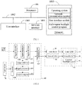
- FIG. 1 is a schematic hardware structure diagram of a television according to an embodiment of the present application.
- the television may include: a processor 1001, such as a CPU, a network interface 1004, a user interface 1003, a memory 1005, and a communication bus 1002.
- the communication bus 1002 is configured to implement connection communication between these components.
- the user interface 1003 may include a display, an input unit such as a keyboard, and optionally the user interface 1003 may further include a standard wired interface and a wireless interface.
- the network interface 1004 may optionally include a standard wired interface and a wireless interface (such as a WI-FI interface).
- the memory 1005 may be a high-speed RAM memory or a stable memory (non-volatile memory), such as a disk memory.
- the memory 1005 may optionally be a storage device independent of the foregoing processor 1001.
- the television may further include a camera, an RF (Radio Frequency) circuit, a sensor, an audio circuit, a WiFi module, and so on.
- the television may also be equipped with other sensors such as gyroscopes, barometers, hygrometers, thermometers, and infrared sensors, which will not be repeated here.
- FIG. 1 does not constitute a limitation on the television, and more or less components than those illustrated may be included, or certain components may be combined, or different components may be arranged.
- the memory 1005 as a computer storage medium may include an operating system, a network communication module, a user interface, and a multi-region backlight control program.
- the network interface 1004 is mainly configured to connect to the back-end server and perform data communication with the back-end server;
- the user interface 1003 is mainly configured to connect to the client (user end) and perform data communication with the client;
- the processor 1001 may be configured to call the multi-region backlight control program stored in the memory 1005 and implement the following operations:
- processor 1001 may call the multi-region backlight control program stored in the memory 1005, and further implements the following operations:
- processor 1001 may call the multi-region backlight control program stored in the memory 1005, and further implements the following operations:
- the processor 1001 may call the multi-region backlight control program stored in the memory 1005, and further implements the following operations: saving, by the signal encoder, image data of a previous frame, optimizing and adjusting, by the signal processor, the image data to obtain the adjustment result, sending, by the signal processor, the adjustment result to the control outputer, processing, by the control outputer, the adjustment result to obtain the first processing result, and sending, by the control outputer, the first processing result to the second driver.
- processor 1001 may call the multi-region backlight control program stored in the memory 1005, and further implements the following operations:
- FIG. 2 is a block schematic diagram of a multi-region backlight control system according to a first embodiment of this application; and FIG. 3 is a light flow diagram of the multi-region backlight control system according to the first embodiment of this application.
- the multi-region backlight control system includes a color liquid crystal display screen 10, a non-color liquid crystal display screen 20, a first driver 30, a second driver 40, a constant backlight source 50, and a main controller 60.
- the color liquid crystal display screen 10 and the non-color liquid crystal display screen 20 are sequentially fixed on the constant backlight source 50, and the non-color liquid crystal display screen 20 is disposed between the color liquid crystal display screen 10 and the constant backlight source 50.
- the main controller 60 is respectively connected with the first driver 30, the second driver 40 and the constant backlight source 50, the first driver 30 is electrically connected with the color liquid crystal display screen 10, and the second driver 40 is electrically connected with the non-color liquid crystal display screen 20.
- the main controller 60 In response to receiving an image signal, the main controller 60 is configured to process the image signal to obtain image data, the main controller 60 is configured to send the image data to the first driver 30 and the second driver 40 synchronously and control the constant backlight source 50 to be turned on.
- the first driver 30 is configured to convert the received image data into a display signal and drive the color liquid crystal display screen 10 to output a display image based on the display signal.
- the second driver 40 is configured to convert the received image data into a control signal and drive the non-color liquid crystal display screen 20 to adjust light transmittance of each pixel of the non-color liquid crystal display screen 20 based on the control signal.
- the color liquid crystal display screen 10 is a liquid crystal display screen with a color filter, that is, the liquid crystal display screen currently used in liquid crystal display products such as televisions, which may output color images.
- the non-color liquid crystal display screen 20 is a liquid crystal display without a color filter, which only includes filters, TFTs and liquid crystals, etc. TFT (Thin Film Transistor) may only output black and white images.
- the constant backlight source 50 may be in the form of a direct array of LED lights, or may be an edge-lit linear arrangement, and may also be other types of backlight sources. This system may be applied to a variety of backlight source solutions.
- the color liquid crystal display screen 10 is the main display screen and the outermost image display of the entire displayer 80.
- the non-color liquid crystal display screen 20 is designed between the color liquid crystal display screen 10 and the constant backlight source 50, which is used as the light transmittance controller of the backlight control system and configured to adjust the light transmittance by controlling the rotation angle of the liquid crystal molecules.
- the main controller 60 outputs the display signal to the color liquid crystal display screen 10 and the control signal to the non-color liquid crystal display screen 20 synchronously, that is, in a certain state, the main controller 60 controls the rotation angles of the liquid crystal molecules of the color liquid crystal display screen 10 and the non-color liquid crystal display screen 20 simultaneously.
- the constant backlight source 50 passes through the non-color liquid crystal display screen 20
- lights of different brightnesses are transmitted through different pixels to achieve the purpose of controlling the brightness and darkness of the multi-region backlight.
- the main controller 60 may output the display signal and the control signal synchronously, which may be realized by setting a synchronization processor 607 in the main controller.
- the synchronization processor 607 may be implemented by a clock signal. For example, when the display signal is output and the clock signal is detected to be converted from low to high, the control signal is controlled to be output, so that the synchronous output of the display signal and the control signal is realized.
- the synchronous output of the display signal and the control signal is realized by the synchronization processor 607, so that the effect of this control mode is more favorable.
- the main controller 60 outputs the display signal and the control signal synchronously to ensure the synchronization of control of the non-color liquid crystal display screen and the color liquid crystal display screen.
- Different regional brightnesses and darknesses in the display signal output by the main controller to the color liquid crystal display screen are calculated through a specific algorithm, so as to synchronously control the switching angle of the liquid crystal molecules in the corresponding region of the non-color liquid crystal display screen to achieve dimming in different regions and improve screen contrast.
- a non-color liquid crystal display screen 20 is set between a color liquid crystal display screen 10 and a constant backlight source 50.
- a main controller 60 processes the image signal to obtain image data and sends the image data to a first driver 30 and a second driver 40 synchronously.
- the first driver 30 converts the image into a display signal, and drives the color liquid crystal display screen 10 to output a display image.
- the second driver 40 converts the image data into a control signal, and drives the non-color liquid crystal display screen 20 to adjust light transmittance of each pixel of the non-color liquid crystal display screen, and cooperates with the constant backlight source 50 to drive the color liquid crystal display screen 10 to display image.
- the main controller 60 may simultaneously control the rotation angle of the liquid crystal molecules of the color liquid crystal display screen 10 and the non-color liquid crystal display screen 20, so that lights of different brightness are transmitted through different pixels, thereby achieving the purpose of controlling the brightness and darkness of the multi-region backlight.
- the display signal and the control signal are synchronously output to ensure the synchronization of the control of the non-color liquid crystal display screen 20 and the color liquid crystal display screen 10.
- different regional brightnesses and darknesses in the display signal are output by the main controller 60 to the color liquid crystal display screen to synchronize the control of the switching angle of the liquid crystal molecules in the corresponding region of the non-color liquid crystal display screen 20 to achieve dimming in different regions and improve the display contrast of the screen.
- the local backlight brightness and darkness is adjusted to improve the dynamic contrast of the display, which greatly reduces light leakage and alleviates the eye fatigue caused by watching the television for a long time. The viewer's eyes gain comfort and the user experience is improved.
- the main controller 60 includes a signal decoder 600, a signal displayer 601, a signal encoder 602, an image collecter 603, a signal processor 604 and a control outputer 605.
- the signal decoder 600, the signal displayer 601, the signal encoder 602 and the first driver 30 are connected in sequence.
- the signal displayer 601, the image collecter 603, the signal processor 604, the control outputer 605 and the second driver 40 are connected in sequence.
- the signal decoder 600 decodes the input image signal, and then the decoded signal is encoded according to the output signal standard through the signal displayer 601 and the signal encoder 602 to output, so as to obtain image data signal and clock signal such as VBO (V-By-One), LVDS to drive the color liquid crystal display screen 10 for display.
- the image signal collecter collects the decoded display signal and adjusts and optimizes the display signal through software algorithms in signal processing to achieve the intended purpose.
- the adjusted and optimized signal that is, the adjustment result, is encoded by the control outputer 605 and output to the second driver 40, thus the purpose of controlling the non-color liquid crystal display screen 20 is achieved.
- the signal processor 604 may use the image data collected in the previous frame for statistics and processing to obtain the corresponding adjustment result, and then re-encode and output the adjustment result through the control outputer 605.
- a new image signal obtained by the second driver 40 is applied in the image display of the next frame, so that the dynamic control of the backlight in different pixel regions of the non-color liquid crystal display screen 20 is realized.
- the multi-region backlight control system further includes a light sensor 70, where the main controller further includes an interface 606.
- the light sensor 70 is connected with the interface 606, and the interface 606 is connected with the signal processor 604.
- the light sensor 70 is configured to detect change of ambient light around a television to obtain detection data, and the light sensor 70 is configured to send the detection data to the signal processor 604 through the interface 606.
- the signal processor 604 is configured to process the detection data after receiving the detection data.
- the light sensor 70 detects changes in ambient light around the television and transmits the detection data to the main controller 60 in real time.
- the main controller 60 converts the collected image signals to perform dynamic compensation adjustment according to the changes in ambient light to enhance or reduce the light transmittance of the backlight in the non-color liquid crystal display screen 20, so as to achieve the enhancement or reduction of the grayscale value displayed by the non-color liquid crystal display screen 20, thereby achieving the purpose of overall enhancement and reduction of the backlight.
- the detected data is A1 to An, where the ambient light corresponding to An is the brightest and the ambient light corresponding to A1 is the darkest.
- This curve may be used to calculate the brightness value L through software algorithm and certain formula and set different modes according to the different scenes of the screen, so as to achieve the purpose of using non-color liquid crystal glass to control the light transmittance to strengthen and reduce the backlight.
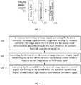
- FIG. 4 is a schematic flowchart of a multi-region backlight control method according to the first embodiment of this application.
- the multi-region backlight control method includes: Step S10: in response to receiving an image signal, processing, by the main controller, the image signal to obtain image data, sending, by the main controller, the image data to the first driver and the second driver synchronously, and controlling, by the main controller, the constant backlight source to be turned on.
- the first driver and the second driver may convert the image data signals and clock signals such as VBO, LVDS, etc. output by the main controller into line field control signals that can be recognized by the liquid crystal display screen.
- the distortion degree of liquid crystal molecules is changed by TFT operation in the control panel of the line field control signal, thereby changing the light transmittance of each pixel, and driving the liquid crystal display screen to display images in cooperation with the backlight.
- Step S20 converting, by the first driver, the received image data into a display signal, and driving, by the first driver, the color liquid crystal display screen to output a display image based on the display signal.
- the first driver converts the received image data into the display signal, and drives the color liquid crystal display screen to output the display image based on the display signal.
- the signal decoder decodes the image signal to obtain image information.
- the signal decoder sends the image information to the signal displayer, and the signal displayer processes the image information to obtain image data.
- the signal displayer sends the image data to the signal encoder, and the encoder encodes according to the output signal standard, and outputs the encoding result to the first driver, so as to convert the encoding result into a display signal, and the first driver drives the color liquid crystal display screen to output the display image based on the display signal.
- Step S30 converting, by the second driver, the received image data into a control signal, and driving, by the second driver, the non-color liquid crystal display screen to adjust light transmittance based on the control signal.
- the second driver converts the received image data into the control signal, and drives the non-color liquid crystal display screen to adjust the light transmittance based on the control signal.
- the main controller may output the display signal and the control signal synchronously, which may be realized by setting a synchronization processor in the main controller.
- the synchronization processor may be implemented by a clock signal. For example, when the display signal is output and the clock signal is detected to be converted from low to high, the control signal is controlled to be output, so that the synchronous output of the display signal and the control signal is realized.
- the synchronous output of the display signal and the control signal is realized by the synchronization processor, so that the effect of this control mode is more favorable.
- the main controller outputs the display signal and the control signal synchronously to ensure the synchronization of control of the non-color liquid crystal display screen and the color liquid crystal display screen.
- Different regional brightnesses and darknesses in the display signal output by the main controller to the color liquid crystal display screen are calculated through a specific algorithm, so as to synchronously control the switching angle of the liquid crystal molecules in the corresponding region of the non-color liquid crystal display screen to achieve dimming in different regions and improve screen contrast.
- the first driver drives the color liquid crystal display screen to output the display image according to the display signal.
- the second driver drives the non-color liquid crystal display screen to adjust its light transmittance according to the control signal, and the main controller controls the constant backlight source to be turned on.
- the signal processor in the main controller may use the image data collected in the previous frame for statistics and processing to obtain the corresponding adjusted image signal, and then re-encode and output the image signal through the control outputer.
- the new image signal obtained by the second driver is applied to the image display of the next frame to realize the dynamic control of the backlight in different pixel regions of the non-color liquid crystal display screen.
- the signal encoder in the main controller may also store the image data of the last frame, and wait for the image collecter, the signal processor and control outputer to process, encode and output the collected signal, and then output at the same time, so that the first driver and the second driver may simultaneously acquire one frame of signal display data. thereby eliminating the display image distortion caused by scene switching.
- a non-color liquid crystal display screen is set between a color liquid crystal display screen and a constant backlight source.
- a main controller processes the image signal to obtain image data and sends the image data to a first driver and a second driver synchronously.
- the first driver converts the image data into a display signal, and drives the color liquid crystal display screen to output a display image.
- the second driver converts the image data into a control signal, and drives the non-color liquid crystal display screen to adjust light transmittance of each pixel of the non-color liquid crystal display screen, and cooperate with the constant backlight source to drive the color liquid crystal display screen to display image.
- the main controller may simultaneously control the rotation angle of the liquid crystal molecules of the color liquid crystal display screen and the non-color liquid crystal display screen, so that lights of different brightness are transmitted through different pixels, thereby achieving the purpose of controlling the brightness and darkness of the multi-region backlight.
- the display signal and the control signal are output synchronously to ensure the synchronization of control of the non-color liquid crystal display screen and the color liquid crystal display screen.
- different regional brightnesses and darknesses in the display signal are output by the main controller to the color liquid crystal display screen, so as to synchronously control the switching angle of the liquid crystal molecules in the corresponding region of the non-color liquid crystal display screen to achieve dimming in different regions and improve screen contrast.
- a second embodiment of the multi-region backlight control method of the present application is provided.
- the main controller includes a signal decoder, a signal displayer, and a signal encoder.
- the signal decoder, the signal displayer, the signal encoder, and the first driver are connected in sequence.
- step S10 includes:
- the first driver and the second driver may convert the image data signals and clock signals such as VBO (V-By-One) (digital interface standard), LVDS (Low Voltage Differential Signal), etc. output by the main controller into line field control signals that can be recognized by the liquid crystal display screen.
- VBO V-By-One
- LVDS Low Voltage Differential Signal
- the distortion degree of liquid crystal molecules is changed by TFT operation in the control panel of the line field control signal, thereby changing the light transmittance of each pixel, and driving the liquid crystal display screen to display images in cooperation with the backlight.
- the signal decoder decodes the input image signal, and then the decoded signal is encoded according to the output signal standard through the signal displayer and the signal encoder to output, so as to obtain image data signal and clock signal such as VBO (V-By-One), LVDS to drive the color liquid crystal display screen 10 for display.
- VBO V-By-One
- step S30 includes:
- control signal is controlled by the image collecter, the signal processor and the control outputer.
- the control outputer may encode the adjustment result to obtain image data signal and clock signal such as VBO (V-By-One) and LVDS, and the image data signal and the clock signal are output to the second driver to realize the synchronous output of the control signal and the display signal.
- the signal processor may use the image data collected in the previous frame for statistics and processing to obtain the corresponding adjustment result, and then re-encode and output the adjustment result through the control outputer.
- a new image signal obtained by the second driver is applied in the image display of the next frame, so that the dynamic control of the backlight in different pixel regions of the non-color liquid crystal display screen is realized.
- step S33 includes: saving, by the signal encoder, image data of a previous frame, optimizing and adjusting, by the signal processor, the image data to obtain the adjustment result, sending, by the signal processor, the adjustment result to the second driver through the control outputer.
- the signal encoder may store the image data of the last frame, and wait for the image collecter, the signal processor and control outputer to process, encode and output the collected signal, and then output at the same time, so that the first driver and the second driver may simultaneously acquire one frame of signal display data to eliminate the display image distortion caused by scene switching.
- a fourth embodiment of the multi-region backlight control method of the present application is provided.
- the multi-region backlight control system further includes a light sensor, the light sensor is connected with an interface, and the interface is connected with the signal processor.
- step S30 further includes:
- the light sensor obtains detection data after detecting changes in ambient light around the television, and the light sensor sends the detection data to the signal processor through the interface.
- the signal processor After receiving the detection data, the signal processor performs dynamic compensation adjustment on the adjustment result to obtain a compensation signal.
- the signal processor sends the compensation signal to the control outputer, and the control outputer processes the compensation signal to obtain a second processing result and send the second processing result to the second driver.
- the second driver converts the second processing result into a control signal and drives the non-color liquid crystal display screen to adjust the light transmittance based on the control signal.
- the light sensor 70 detects changes in ambient light around the television and transmits the detection data to the main controller 60 in real time.
- the main controller 60 converts the collected image signals to perform dynamic compensation adjustment according to the changes in ambient light to enhance or reduce the light transmittance of the backlight in the non-color liquid crystal display screen 20, so as to achieve the enhancement or reduction of the grayscale value displayed by the non-color liquid crystal display screen 20, thereby achieving the purpose of overall enhancement and reduction of the backlight.
- the detected data is A1 to An, where the ambient light corresponding to An is the brightest and the ambient light corresponding to A1 is the darkest.
- This curve may be used to calculate the brightness value L through software algorithm and certain formula and set different modes according to the different scenes of the screen, so as to achieve the purpose of using non-color liquid crystal glass to control the light transmittance to strengthen and reduce the backlight.
- an embodiment of the present application further provides a readable storage medium on which a multi-region backlight control program is stored, and when the multi-region backlight control program is executed by a processor, the steps of the multi-region backlight control method described above are implemented.
- the methods in the above embodiments can be implemented by means of software plus a necessary general hardware platform, and of course, can also be implemented by hardware, but in many cases the former is the better.
- the technical solution of the present application can be embodied in the form of a software product in essence or part that contributes to the existing technology, and the computer software product is stored in a storage medium as described above (such as a ROM/RAM, a magnetic disk, an optical disk), including several instructions to enable a device device (which may be a mobile phone, computer, server, air conditioner, or network equipment, etc.) to perform the method described in each embodiment of the present application.
Landscapes
- Engineering & Computer Science (AREA)
- Physics & Mathematics (AREA)
- Computer Hardware Design (AREA)
- General Physics & Mathematics (AREA)
- Theoretical Computer Science (AREA)
- Multimedia (AREA)
- Signal Processing (AREA)
- Chemical & Material Sciences (AREA)
- Crystallography & Structural Chemistry (AREA)
- Liquid Crystal Display Device Control (AREA)
- Control Of Indicators Other Than Cathode Ray Tubes (AREA)
Abstract
Description
- The present application which claims the priority of Chinese Patent Application with No.
201810766756.5 - The present application relates to the technical field of television, in particular to a multi-region backlight control system, a multi-region backlight method, a television and a readable storage medium.
- At present, the liquid crystal display regional backlight brightness control scheme for televisions and other display fields is taking LED (Light Emitting Diode) array as a light source, coordinating with the system to matrix-divide the image signal and calculate the data corresponding to the grayscale values of different matrix addresses through communication protocols such as SPI and control equipment such as multi-region matrix controller, and controlling the matrix controller to output the corresponding PWM signal to control the brightness and darkness of each LED to achieve the control of the brightness and darkness of the backlight in different regions, so as to achieve the purpose of multi-region local dimming to reduce screen light leakage and improve dynamic contrast.
- However, with the continuous improvement of liquid crystal display resolution, 4K, 8K and other display technologies continue to mature, the market demand continues to expand, the number of backlight LED lights, the complexity of the design of the multi-region matrix controller, the maximum number of controllable regions, heat dissipation, the main controller scheme and other aspects are limited. The multi-region backlight technology still cannot achieve pixel-level control, and cannot achieve smaller area brightness changes and higher contrast.
- The main object of the present application is to provide a multi-region backlight control system, a multi-region backlight control method, a television and a readable storage medium, aiming to solve the technical problems that the multi-region backlight technology in the prior art cannot achieve smaller regional brightness changes and higher contrast.
- In order to achieve the above object, the present application provides a multi-region backlight control system including a color liquid crystal display screen, a non-color liquid crystal display screen, a first driver, a second driver, a constant backlight source, and a main controller; the color liquid crystal display screen and the non-color liquid crystal display screen are sequentially fixed on the constant backlight source, and the non-color liquid crystal display screen is disposed between the color liquid crystal display screen and the constant backlight source; the main controller is respectively connected with the first driver, the second driver and the constant backlight source, the first driver is electrically connected with the color liquid crystal display screen, and the second driver is electrically connected with the non-color liquid crystal display screen;
- in response to receiving an image signal, the main controller is configured to process the image signal to obtain image data, the main controller is configured to send the image data to the first driver and the second driver synchronously and control the constant backlight source to be turned on; the first driver is configured to convert the received image data into a display signal and drive the color liquid crystal display screen to output a display image based on the display signal; the second driver is configured to convert the received image data into a control signal and drive the non-color liquid crystal display screen to adjust light transmittance of each pixel of the non-color liquid crystal display screen based on the control signal.
- Preferably, the main controller includes a signal decoder, a signal displayer, a signal encoder, an image collecter, a signal processor and a control outputer; the signal decoder, the signal displayer, the signal encoder and the first driver are connected in sequence; the signal displayer, the image collecter, the signal processor, the control outputer and the second driver are connected in sequence.
- Preferably, the multi-region backlight control system further includes a light sensor, where the main controller further includes an interface; the light sensor is connected with the interface, and the interface is connected with the signal processor; the light sensor is configured to detect change of ambient light around a television to obtain detection data, and the light sensor is configured to send the detection data to the signal processor through the interface; the signal processor is configured to process the detection data after receiving the detection data.
- The present application further provides a multi-region backlight control method, which is applied to a television. The television includes the multi-region backlight control system described above. The multi-region backlight control method includes the following steps:
- in response to receiving an image signal, processing, by the main controller, the image signal to obtain image data, sending, by the main controller, the image data to the first driver and the second driver synchronously, and controlling, by the main controller, the constant backlight source to be turned on;
- converting, by the first driver, the received image data into a display signal, and driving, by the first driver, the color liquid crystal display screen to output a display image based on the display signal; and
- converting, by the second driver, the received image data into a control signal, and driving, by the second driver, the non-color liquid crystal display screen to adjust light transmittance based on the control signal.
- Preferably, the main controller includes a signal decoder, a signal displayer and a signal encoder; the signal decoder, the signal displayer, the signal encoder and the first driver are connected in sequence; where the step of in response to receiving an image signal, processing, by the main controller, the image signal to obtain image data, sending, by the main controller, the image data to the first driver and the second driver synchronously includes:
- in response to receiving the image signal, decoding, by the signal decoder, the image signal to obtain image information;
- processing, by the signal displayer, the received image information to obtain the image data;
- sending, by the signal displayer, the image data to the signal encoder and the second driver; and
- encoding, by the signal encoder, the received image data according to an output signal standard to obtain an encoding result, and outputting, by the signal encoder, the encoding result to the first driver.
- Preferably, the main controller further includes an image collecter, a signal processor and a control outputer; the signal displayer, the image collecter, the signal processor, the control outputer and the second driver are connected in sequence; where the step of converting, by the second driver, the received image data into a control signal, and driving, by the second driver, the non-color liquid crystal display screen to adjust light transmittance based on the control signal includes:
- subsequent to collecting the image data sent by the signal displayer, sending, by the image collecter, the image data to the signal processor;
- optimizing and adjusting, by the signal processor, the received image data to obtain an adjustment result;
- sending, by the signal processor, the adjustment result to the control outputer, processing, by the control outputer, the adjustment result to obtain a first processing result, and sending, by the control outputer, the first processing result to the second driver; and
- subsequent to receiving the first processing result, converting, by the second driver, the first processing result into the control signal, and driving, by the second driver, the non-color liquid crystal display screen to adjust the light transmittance based on the control signal.
- Preferably, the step of sending, by the signal processor, the adjustment result to the second driver through the control outputer includes:
saving, by the signal encoder, image data of a previous frame, optimizing and adjusting, by the signal processor, the image data to obtain the adjustment result, sending, by the signal processor, the adjustment result to the control outputer, processing, by the control outputer, the adjustment result to obtain the second processing result, and sending, by the control outputer, the first processing result to the second driver. - Preferably, the multi-region backlight control system further includes a light sensor, and the main controller further comprises an interface; the light sensor is connected with the interface, and the interface is connected with the signal processor; where the step of subsequent to receiving the image data, converting, by the second driver, the image data into the control signal further includes:
- detecting, by the light sensor, change of ambient light around a television to obtain detection data, and sending, by the light sensor, the detection data to the signal processor through the interface;
- subsequent to receiving the detection data, dynamically compensating and adjusting, by the signal processor, the adjustment result to obtain a compensation signal;
- sending, by the signal processor, the compensation signal to the control outputer, processing, by the control outputer, the compensation signal to obtain a second processing result, and sending, by the control outputer, the second processing result to the second driver; and
- subsequent to receiving the second processing result, converting, by the second driver, the second processing result into the control signal, and driving, by the second driver, the non-color liquid crystal display screen to adjust the light transmittance based on the control signal.
- In addition, in order to achieve the above object, the present application further provides a television, including a memory, a processor, and a multi-region backlight control program stored on the memory and operable on the processor, the multi-region backlight control program, when executed by the processor, implements the steps of any one of the multi-region backlight control method described above.
- In addition, in order to achieve the above object, the present application further provides a readable storage medium, a multi-region backlight control program is stored on the readable storage medium, the multi-region backlight control program, when executed by a processor, implements the steps of any one of the multi-region backlight control method described above.
- In this application, a non-color liquid crystal display screen is set between a color liquid crystal display screen and a constant backlight source. When receiving an image signal, a main controller processes the image signal to obtain image data and sends the image data to a first driver and a second driver synchronously. The first driver converts the image data into a display signal, and drives the color liquid crystal display screen to output a display image. Meanwhile, the second driver converts the image data into a control signal, and drives the non-color liquid crystal display screen to adjust light transmittance of each pixel of the non-color liquid crystal display screen, and cooperates with the constant backlight source to drive the color liquid crystal display screen to display image. It is realized that in a certain state, the main controller may simultaneously control the rotation angle of the liquid crystal molecules of the color liquid crystal display screen and the non-color liquid crystal display screen, so that lights of different brightness are transmitted through different pixels, thereby achieving the purpose of controlling the brightness and darkness of the multi-region backlight. In this application, the display signal and the control signal are synchronously output to ensure the synchronization of the control of the non-color liquid crystal display screen and the color liquid crystal display screen. At the same time, different regional brightnesses and darknesses in the display signal are output by the main controller to the color liquid crystal display screen to synchronize the control of the switching angle of the liquid crystal molecules in the corresponding region of the non-color liquid crystal display screen to achieve dimming in different regions and improve the display contrast of the screen. The local backlight brightness and darkness is adjusted to improve the dynamic contrast of the display, which greatly reduces light leakage and alleviates the eye fatigue caused by watching the television for a long time. The viewer's eyes gain comfort and the user experience is improved.
-
-
FIG. 1 is a schematic hardware structure diagram of a television according to an embodiment of the present application; -
FIG. 2 is a block schematic diagram of a multi-region backlight control system according to a first embodiment of this application; -
FIG. 3 is a light flow diagram of the multi-region backlight control system according to the first embodiment of this application; -
FIG. 4 is a schematic flowchart of a multi-region backlight control method according to the first embodiment of this application; -
FIG. 5 is a schematic flowchart of the multi-region backlight control method according to a second embodiment of this application; -
FIG. 6 is a schematic flowchart of the multi-region backlight control method according to a third embodiment of this application; -
FIG. 7 is a schematic flowchart of the multi-region backlight control method according to a fourth embodiment of this application; and -
FIG. 8 is a diagram of gray-scale brightness changes of the multi-region backlight control method according to the fourth embodiment of this application. -
[Table 1] No. Reference numeral No. Reference numeral 10 Color liquid crystal display screen 20 Non-color liquid crystal display screen 30 First driver 40 Second driver 50 Constant backlight source 60 Main controller 600 Signal decoder 601 Signal displayer 602 Signal encoder 603 Image collecter 604 Signal processor 605 Control outputer 606 Interface 607 Synchronization processor 70 Light sensor 80 Displayer - The purposes, functional features and advantages of this application will be further described in conjunction with the embodiments and with reference to the drawings.
- It should be understood that the specific embodiments described herein are only used to explain the present application, and are not used to limit the present application.
- As shown in
FIG. 1, FIG. 1 is a schematic hardware structure diagram of a television according to an embodiment of the present application. - As shown in
FIG. 1 , the television may include: aprocessor 1001, such as a CPU, anetwork interface 1004, auser interface 1003, amemory 1005, and acommunication bus 1002. Thecommunication bus 1002 is configured to implement connection communication between these components. Theuser interface 1003 may include a display, an input unit such as a keyboard, and optionally theuser interface 1003 may further include a standard wired interface and a wireless interface. Thenetwork interface 1004 may optionally include a standard wired interface and a wireless interface (such as a WI-FI interface). Thememory 1005 may be a high-speed RAM memory or a stable memory (non-volatile memory), such as a disk memory. Thememory 1005 may optionally be a storage device independent of the foregoingprocessor 1001. - Optionally, the television may further include a camera, an RF (Radio Frequency) circuit, a sensor, an audio circuit, a WiFi module, and so on. Certainly, the television may also be equipped with other sensors such as gyroscopes, barometers, hygrometers, thermometers, and infrared sensors, which will not be repeated here.
- Those skilled in the art may understand that the structure of the television shown in
FIG. 1 does not constitute a limitation on the television, and more or less components than those illustrated may be included, or certain components may be combined, or different components may be arranged. - As shown in
FIG. 1 , thememory 1005 as a computer storage medium may include an operating system, a network communication module, a user interface, and a multi-region backlight control program. - In the television shown in
FIG. 1 , thenetwork interface 1004 is mainly configured to connect to the back-end server and perform data communication with the back-end server; theuser interface 1003 is mainly configured to connect to the client (user end) and perform data communication with the client; and theprocessor 1001 may be configured to call the multi-region backlight control program stored in thememory 1005 and implement the following operations: - in response to receiving an image signal, processing, by a main controller, the image signal to obtain image data, sending, by the main controller, the image data to a first driver and a second driver synchronously, and controlling, by the main controller, a constant backlight source to be turned on;
- converting, by the first driver, the received image data into a display signal, and driving, by the first driver, the color liquid crystal display screen to output a display image based on the display signal; and
- converting, by the second driver, the received image data into a control signal, and driving, by the second driver, the non-color liquid crystal display screen to adjust light transmittance based on the control signal.
- Further, the
processor 1001 may call the multi-region backlight control program stored in thememory 1005, and further implements the following operations: - in response to receiving the image signal, decoding, by a signal decoder, the image signal to obtain image information;
- processing, by a signal displayer, the received image information to obtain the image data;
- sending, by the signal displayer, the image data to a signal encoder and the second driver; and
- encoding, by the signal encoder, the received image data according to an output signal standard to obtain an encoding result, and outputting, by the signal encoder, the encoding result to the first driver.
- Further, the
processor 1001 may call the multi-region backlight control program stored in thememory 1005, and further implements the following operations: - subsequent to collecting the image data sent by the signal displayer, sending, by the image collecter, the image data to the signal processor;
- optimizing and adjusting, by the signal processor, the received image data to obtain an adjustment result;
- sending, by the signal processor, the adjustment result to a control outputer, processing, by a control outputer, the adjustment result to obtain a first processing result, and sending, by the control outputer, the first processing result to the second driver; and
- subsequent to receiving the first processing result, converting, by the second driver, the first processing result into the control signal, and driving, by the second driver, the non-color liquid crystal display screen to adjust the light transmittance based on the control signal.
- Further, the
processor 1001 may call the multi-region backlight control program stored in thememory 1005, and further implements the following operations:
saving, by the signal encoder, image data of a previous frame, optimizing and adjusting, by the signal processor, the image data to obtain the adjustment result, sending, by the signal processor, the adjustment result to the control outputer, processing, by the control outputer, the adjustment result to obtain the first processing result, and sending, by the control outputer, the first processing result to the second driver. - Further, the
processor 1001 may call the multi-region backlight control program stored in thememory 1005, and further implements the following operations: - detecting, by the light sensor, change of ambient light around a television to obtain detection data, and sending, by the light sensor, the detection data to the signal processor through the interface;
- subsequent to receiving the detection data, dynamically compensating and adjusting, by the signal processor, the adjustment result to obtain a compensation signal;
- sending, by the signal processor, the compensation signal to the control outputer, processing, by the control outputer, the compensation signal to obtain a second processing result, and sending, by the control outputer, the second processing result to the second driver; and
- subsequent to receiving the second processing result, converting, by the second driver, the second processing result into the control signal, and driving, by the second driver, the non-color liquid crystal display screen to adjust the light transmittance based on the control signal.
- Referring to
FIGS. 2 to 3 ,FIG. 2 is a block schematic diagram of a multi-region backlight control system according to a first embodiment of this application; andFIG. 3 is a light flow diagram of the multi-region backlight control system according to the first embodiment of this application. - In the first embodiment, the multi-region backlight control system includes a color liquid
crystal display screen 10, a non-color liquidcrystal display screen 20, afirst driver 30, asecond driver 40, aconstant backlight source 50, and amain controller 60. The color liquidcrystal display screen 10 and the non-color liquidcrystal display screen 20 are sequentially fixed on theconstant backlight source 50, and the non-color liquidcrystal display screen 20 is disposed between the color liquidcrystal display screen 10 and theconstant backlight source 50. Themain controller 60 is respectively connected with thefirst driver 30, thesecond driver 40 and theconstant backlight source 50, thefirst driver 30 is electrically connected with the color liquidcrystal display screen 10, and thesecond driver 40 is electrically connected with the non-color liquidcrystal display screen 20. - In response to receiving an image signal, the
main controller 60 is configured to process the image signal to obtain image data, themain controller 60 is configured to send the image data to thefirst driver 30 and thesecond driver 40 synchronously and control theconstant backlight source 50 to be turned on. Thefirst driver 30 is configured to convert the received image data into a display signal and drive the color liquidcrystal display screen 10 to output a display image based on the display signal. Thesecond driver 40 is configured to convert the received image data into a control signal and drive the non-color liquidcrystal display screen 20 to adjust light transmittance of each pixel of the non-color liquidcrystal display screen 20 based on the control signal. - The color liquid
crystal display screen 10 is a liquid crystal display screen with a color filter, that is, the liquid crystal display screen currently used in liquid crystal display products such as televisions, which may output color images. The non-color liquidcrystal display screen 20 is a liquid crystal display without a color filter, which only includes filters, TFTs and liquid crystals, etc. TFT (Thin Film Transistor) may only output black and white images. Theconstant backlight source 50 may be in the form of a direct array of LED lights, or may be an edge-lit linear arrangement, and may also be other types of backlight sources. This system may be applied to a variety of backlight source solutions. The color liquidcrystal display screen 10 is the main display screen and the outermost image display of theentire displayer 80. The non-color liquidcrystal display screen 20 is designed between the color liquidcrystal display screen 10 and theconstant backlight source 50, which is used as the light transmittance controller of the backlight control system and configured to adjust the light transmittance by controlling the rotation angle of the liquid crystal molecules. Themain controller 60 outputs the display signal to the color liquidcrystal display screen 10 and the control signal to the non-color liquidcrystal display screen 20 synchronously, that is, in a certain state, themain controller 60 controls the rotation angles of the liquid crystal molecules of the color liquidcrystal display screen 10 and the non-color liquidcrystal display screen 20 simultaneously. After theconstant backlight source 50 passes through the non-color liquidcrystal display screen 20, lights of different brightnesses are transmitted through different pixels to achieve the purpose of controlling the brightness and darkness of the multi-region backlight. - The
main controller 60 may output the display signal and the control signal synchronously, which may be realized by setting asynchronization processor 607 in the main controller. Thesynchronization processor 607 may be implemented by a clock signal. For example, when the display signal is output and the clock signal is detected to be converted from low to high, the control signal is controlled to be output, so that the synchronous output of the display signal and the control signal is realized. The synchronous output of the display signal and the control signal is realized by thesynchronization processor 607, so that the effect of this control mode is more favorable. This application has been proved by experiments that, even if thesynchronization processor 607 is not provided, the difference between the output of the display signal and the output of the control signal is only a few milliseconds, and the human eye cannot perceive it when viewing the display image, which does not affect the viewing effect. Themain controller 60 outputs the display signal and the control signal synchronously to ensure the synchronization of control of the non-color liquid crystal display screen and the color liquid crystal display screen. Different regional brightnesses and darknesses in the display signal output by the main controller to the color liquid crystal display screen are calculated through a specific algorithm, so as to synchronously control the switching angle of the liquid crystal molecules in the corresponding region of the non-color liquid crystal display screen to achieve dimming in different regions and improve screen contrast. - In this application, a non-color liquid
crystal display screen 20 is set between a color liquidcrystal display screen 10 and aconstant backlight source 50. When receiving an image signal, amain controller 60 processes the image signal to obtain image data and sends the image data to afirst driver 30 and asecond driver 40 synchronously. Thefirst driver 30 converts the image into a display signal, and drives the color liquidcrystal display screen 10 to output a display image. Meanwhile, thesecond driver 40 converts the image data into a control signal, and drives the non-color liquidcrystal display screen 20 to adjust light transmittance of each pixel of the non-color liquid crystal display screen, and cooperates with theconstant backlight source 50 to drive the color liquidcrystal display screen 10 to display image. It is realized that in a certain state, themain controller 60 may simultaneously control the rotation angle of the liquid crystal molecules of the color liquidcrystal display screen 10 and the non-color liquidcrystal display screen 20, so that lights of different brightness are transmitted through different pixels, thereby achieving the purpose of controlling the brightness and darkness of the multi-region backlight. In this application, the display signal and the control signal are synchronously output to ensure the synchronization of the control of the non-color liquidcrystal display screen 20 and the color liquidcrystal display screen 10. At the same time, different regional brightnesses and darknesses in the display signal are output by themain controller 60 to the color liquid crystal display screen to synchronize the control of the switching angle of the liquid crystal molecules in the corresponding region of the non-color liquidcrystal display screen 20 to achieve dimming in different regions and improve the display contrast of the screen. The local backlight brightness and darkness is adjusted to improve the dynamic contrast of the display, which greatly reduces light leakage and alleviates the eye fatigue caused by watching the television for a long time. The viewer's eyes gain comfort and the user experience is improved. - Preferably, the
main controller 60 includes asignal decoder 600, asignal displayer 601, asignal encoder 602, animage collecter 603, asignal processor 604 and acontrol outputer 605. Thesignal decoder 600, thesignal displayer 601, thesignal encoder 602 and thefirst driver 30 are connected in sequence. Thesignal displayer 601, theimage collecter 603, thesignal processor 604, the control outputer 605 and thesecond driver 40 are connected in sequence. Thesignal decoder 600 decodes the input image signal, and then the decoded signal is encoded according to the output signal standard through thesignal displayer 601 and thesignal encoder 602 to output, so as to obtain image data signal and clock signal such as VBO (V-By-One), LVDS to drive the color liquidcrystal display screen 10 for display. The image signal collecter collects the decoded display signal and adjusts and optimizes the display signal through software algorithms in signal processing to achieve the intended purpose. The adjusted and optimized signal, that is, the adjustment result, is encoded by the control outputer 605 and output to thesecond driver 40, thus the purpose of controlling the non-color liquidcrystal display screen 20 is achieved. Thesignal processor 604 may use the image data collected in the previous frame for statistics and processing to obtain the corresponding adjustment result, and then re-encode and output the adjustment result through thecontrol outputer 605. A new image signal obtained by thesecond driver 40 is applied in the image display of the next frame, so that the dynamic control of the backlight in different pixel regions of the non-color liquidcrystal display screen 20 is realized. - Preferably, the multi-region backlight control system further includes a
light sensor 70, where the main controller further includes aninterface 606. Thelight sensor 70 is connected with theinterface 606, and theinterface 606 is connected with thesignal processor 604. Thelight sensor 70 is configured to detect change of ambient light around a television to obtain detection data, and thelight sensor 70 is configured to send the detection data to thesignal processor 604 through theinterface 606. Thesignal processor 604 is configured to process the detection data after receiving the detection data. - As shown in
FIG. 8 , thelight sensor 70 detects changes in ambient light around the television and transmits the detection data to themain controller 60 in real time. Themain controller 60 converts the collected image signals to perform dynamic compensation adjustment according to the changes in ambient light to enhance or reduce the light transmittance of the backlight in the non-color liquidcrystal display screen 20, so as to achieve the enhancement or reduction of the grayscale value displayed by the non-color liquidcrystal display screen 20, thereby achieving the purpose of overall enhancement and reduction of the backlight. For example, when the ambient light is different, the detected data is A1 to An, where the ambient light corresponding to An is the brightest and the ambient light corresponding to A1 is the darkest. The software uses the formula L=aA2+bA+C and the algorithm to set the brightness value of the output signal corresponding to A1 as L1 and set the brightness value of the output signal corresponding to An as Ln, where L1 to Ln correspond to gray-scale brightness change curve of the output signal. This curve may be used to calculate the brightness value L through software algorithm and certain formula and set different modes according to the different scenes of the screen, so as to achieve the purpose of using non-color liquid crystal glass to control the light transmittance to strengthen and reduce the backlight. - Referring to
FIG. 4, FIG. 4 is a schematic flowchart of a multi-region backlight control method according to the first embodiment of this application. - In the first embodiment, the multi-region backlight control method includes:
Step S10: in response to receiving an image signal, processing, by the main controller, the image signal to obtain image data, sending, by the main controller, the image data to the first driver and the second driver synchronously, and controlling, by the main controller, the constant backlight source to be turned on. - In this embodiment, the first driver and the second driver may convert the image data signals and clock signals such as VBO, LVDS, etc. output by the main controller into line field control signals that can be recognized by the liquid crystal display screen. The distortion degree of liquid crystal molecules is changed by TFT operation in the control panel of the line field control signal, thereby changing the light transmittance of each pixel, and driving the liquid crystal display screen to display images in cooperation with the backlight.
- Step S20: converting, by the first driver, the received image data into a display signal, and driving, by the first driver, the color liquid crystal display screen to output a display image based on the display signal.
- In this embodiment, the first driver converts the received image data into the display signal, and drives the color liquid crystal display screen to output the display image based on the display signal. When the image signal is received, the signal decoder decodes the image signal to obtain image information. The signal decoder sends the image information to the signal displayer, and the signal displayer processes the image information to obtain image data. The signal displayer sends the image data to the signal encoder, and the encoder encodes according to the output signal standard, and outputs the encoding result to the first driver, so as to convert the encoding result into a display signal, and the first driver drives the color liquid crystal display screen to output the display image based on the display signal.
- Step S30: converting, by the second driver, the received image data into a control signal, and driving, by the second driver, the non-color liquid crystal display screen to adjust light transmittance based on the control signal.
- In this embodiment, the second driver converts the received image data into the control signal, and drives the non-color liquid crystal display screen to adjust the light transmittance based on the control signal. The main controller may output the display signal and the control signal synchronously, which may be realized by setting a synchronization processor in the main controller. The synchronization processor may be implemented by a clock signal. For example, when the display signal is output and the clock signal is detected to be converted from low to high, the control signal is controlled to be output, so that the synchronous output of the display signal and the control signal is realized. The synchronous output of the display signal and the control signal is realized by the synchronization processor, so that the effect of this control mode is more favorable. This application has been proved by experiments that, even if the synchronization processor is not provided, the difference between the output of the display signal and the output of the control signal is only a few milliseconds, and the human eye cannot perceive it when viewing the display image, which does not affect the viewing effect. The main controller outputs the display signal and the control signal synchronously to ensure the synchronization of control of the non-color liquid crystal display screen and the color liquid crystal display screen. Different regional brightnesses and darknesses in the display signal output by the main controller to the color liquid crystal display screen are calculated through a specific algorithm, so as to synchronously control the switching angle of the liquid crystal molecules in the corresponding region of the non-color liquid crystal display screen to achieve dimming in different regions and improve screen contrast. The first driver drives the color liquid crystal display screen to output the display image according to the display signal. At the same time, the second driver drives the non-color liquid crystal display screen to adjust its light transmittance according to the control signal, and the main controller controls the constant backlight source to be turned on. In order to output the display signal and the control signal synchronously, the signal processor in the main controller may use the image data collected in the previous frame for statistics and processing to obtain the corresponding adjusted image signal, and then re-encode and output the image signal through the control outputer. The new image signal obtained by the second driver is applied to the image display of the next frame to realize the dynamic control of the backlight in different pixel regions of the non-color liquid crystal display screen. In addition, the signal encoder in the main controller may also store the image data of the last frame, and wait for the image collecter, the signal processor and control outputer to process, encode and output the collected signal, and then output at the same time, so that the first driver and the second driver may simultaneously acquire one frame of signal display data. thereby eliminating the display image distortion caused by scene switching.
- In this application, a non-color liquid crystal display screen is set between a color liquid crystal display screen and a constant backlight source. When receiving an image signal, a main controller processes the image signal to obtain image data and sends the image data to a first driver and a second driver synchronously. The first driver converts the image data into a display signal, and drives the color liquid crystal display screen to output a display image. Meanwhile, the second driver converts the image data into a control signal, and drives the non-color liquid crystal display screen to adjust light transmittance of each pixel of the non-color liquid crystal display screen, and cooperate with the constant backlight source to drive the color liquid crystal display screen to display image. It is realized that in a certain state, the main controller may simultaneously control the rotation angle of the liquid crystal molecules of the color liquid crystal display screen and the non-color liquid crystal display screen, so that lights of different brightness are transmitted through different pixels, thereby achieving the purpose of controlling the brightness and darkness of the multi-region backlight. In this application, the display signal and the control signal are output synchronously to ensure the synchronization of control of the non-color liquid crystal display screen and the color liquid crystal display screen. At the same time, different regional brightnesses and darknesses in the display signal are output by the main controller to the color liquid crystal display screen, so as to synchronously control the switching angle of the liquid crystal molecules in the corresponding region of the non-color liquid crystal display screen to achieve dimming in different regions and improve screen contrast.
- Based on the first embodiment, a second embodiment of the multi-region backlight control method of the present application is provided. The main controller includes a signal decoder, a signal displayer, and a signal encoder. The signal decoder, the signal displayer, the signal encoder, and the first driver are connected in sequence. Referring to
FIG. 5 , step S10 includes: - S11: in response to receiving the image signal, decoding, by the signal decoder, the image signal to obtain image information;
- S12: processing, by the signal displayer, the received image information to obtain the image data;
- S13: sending, by the signal displayer, the image data to the signal encoder and the second driver; and
- S14: encoding, by the signal encoder, the received image data according to an output signal standard to obtain an encoding result, and outputting, by the signal encoder, the encoding result to the first driver.
- In this embodiment, the first driver and the second driver may convert the image data signals and clock signals such as VBO (V-By-One) (digital interface standard), LVDS (Low Voltage Differential Signal), etc. output by the main controller into line field control signals that can be recognized by the liquid crystal display screen. The distortion degree of liquid crystal molecules is changed by TFT operation in the control panel of the line field control signal, thereby changing the light transmittance of each pixel, and driving the liquid crystal display screen to display images in cooperation with the backlight. The signal decoder decodes the input image signal, and then the decoded signal is encoded according to the output signal standard through the signal displayer and the signal encoder to output, so as to obtain image data signal and clock signal such as VBO (V-By-One), LVDS to drive the color liquid
crystal display screen 10 for display. - Based on the second embodiment, a third embodiment of the multi-region backlight control method of the present application is provided. The main controller further includes an image collecter, a signal processor and a control outputer. The signal displayer, the image collecter, the signal processor, the control outputer and the second driver are connected in sequence. Please refer to
FIG. 6 , step S30 includes: - S31: subsequent to collecting the image data sent by the signal displayer, sending, by the image collecter, the image data to the signal processor;
- S32: subsequent to receiving the image data, optimizing and adjusting, by the signal processor, the image data to obtain an adjustment result;
- S33: sending, by the signal processor, the adjustment result to the control outputer, processing, by the control outputer, the adjustment result to obtain a first processing result, and sending, by the control outputer, the first processing result to the second driver; and
- S34: subsequent to receiving the first processing result, converting, by the second driver, the first processing result into the control signal, and driving, by the second driver, the non-color liquid crystal display screen to adjust the light transmittance based on the control signal.
- In this embodiment, the control signal is controlled by the image collecter, the signal processor and the control outputer. The control outputer may encode the adjustment result to obtain image data signal and clock signal such as VBO (V-By-One) and LVDS, and the image data signal and the clock signal are output to the second driver to realize the synchronous output of the control signal and the display signal. The signal processor may use the image data collected in the previous frame for statistics and processing to obtain the corresponding adjustment result, and then re-encode and output the adjustment result through the control outputer. A new image signal obtained by the second driver is applied in the image display of the next frame, so that the dynamic control of the backlight in different pixel regions of the non-color liquid crystal display screen is realized.
- Further, step S33 includes:
saving, by the signal encoder, image data of a previous frame, optimizing and adjusting, by the signal processor, the image data to obtain the adjustment result, sending, by the signal processor, the adjustment result to the second driver through the control outputer. - In this embodiment, the signal encoder may store the image data of the last frame, and wait for the image collecter, the signal processor and control outputer to process, encode and output the collected signal, and then output at the same time, so that the first driver and the second driver may simultaneously acquire one frame of signal display data to eliminate the display image distortion caused by scene switching.
- Based on the third embodiment, a fourth embodiment of the multi-region backlight control method of the present application is provided. The multi-region backlight control system further includes a light sensor, the light sensor is connected with an interface, and the interface is connected with the signal processor. Please refer to
FIG. 6 , step S30 further includes: - S35: detecting, by the light sensor, change of ambient light around a television to obtain detection data, and sending, by the light sensor, the detection data to the signal processor through the interface;
- S36: subsequent to receiving the detection data, dynamically compensating and adjusting, by the signal processor, the adjustment result to obtain a compensation signal;
- S37: sending, by the signal processor, the compensation signal to the control outputer, processing, by the control outputer, the compensation signal to obtain a second processing result, and sending, by the control outputer, the second processing result to the second driver; and
- S38: subsequent to receiving the second processing result, converting, by the second driver, the second processing result into the control signal, and driving, by the second driver, the non-color liquid crystal display screen to adjust the light transmittance based on the control signal.
- In this embodiment, the light sensor obtains detection data after detecting changes in ambient light around the television, and the light sensor sends the detection data to the signal processor through the interface. After receiving the detection data, the signal processor performs dynamic compensation adjustment on the adjustment result to obtain a compensation signal. The signal processor sends the compensation signal to the control outputer, and the control outputer processes the compensation signal to obtain a second processing result and send the second processing result to the second driver. After receiving the second processing result, the second driver converts the second processing result into a control signal and drives the non-color liquid crystal display screen to adjust the light transmittance based on the control signal. As shown in
FIG. 8 , thelight sensor 70 detects changes in ambient light around the television and transmits the detection data to themain controller 60 in real time. Themain controller 60 converts the collected image signals to perform dynamic compensation adjustment according to the changes in ambient light to enhance or reduce the light transmittance of the backlight in the non-color liquidcrystal display screen 20, so as to achieve the enhancement or reduction of the grayscale value displayed by the non-color liquidcrystal display screen 20, thereby achieving the purpose of overall enhancement and reduction of the backlight. For example, when the ambient light is different, the detected data is A1 to An, where the ambient light corresponding to An is the brightest and the ambient light corresponding to A1 is the darkest. The software uses the formula L=aA2+bA+C and the algorithm to set the brightness value of the output signal corresponding to A1 as L1 and set the brightness value of the output signal corresponding to An as Ln, where L1 to Ln correspond to gray-scale brightness change curve of the output signal. This curve may be used to calculate the brightness value L through software algorithm and certain formula and set different modes according to the different scenes of the screen, so as to achieve the purpose of using non-color liquid crystal glass to control the light transmittance to strengthen and reduce the backlight. - In addition, an embodiment of the present application further provides a readable storage medium on which a multi-region backlight control program is stored, and when the multi-region backlight control program is executed by a processor, the steps of the multi-region backlight control method described above are implemented.
- The specific embodiments of the readable storage medium of the present application are basically the same as the various embodiments of the multi-region backlight control system described above, and are not repeated here.
- It should be noted that in this article, the terms "comprise", "include" or any other variant thereof are intended to cover non-exclusive inclusion, so that a process, method, article or device that includes a series of elements includes not only those elements, but also other elements that are not explicitly listed, or include elements inherent to such processes, methods, objects, or devices. Without more restrictions, the element defined by the sentence "comprise a..." does not exclude that there are other identical elements in the process, method, article or device that includes the element.
- The sequence numbers of the above embodiments of the present application are for description only, and do not represent the advantages and disadvantages of the embodiments.
- Through the description of the above embodiments, those skilled in the art can clearly understand that the methods in the above embodiments can be implemented by means of software plus a necessary general hardware platform, and of course, can also be implemented by hardware, but in many cases the former is the better. Based on this understanding, the technical solution of the present application can be embodied in the form of a software product in essence or part that contributes to the existing technology, and the computer software product is stored in a storage medium as described above (such as a ROM/RAM, a magnetic disk, an optical disk), including several instructions to enable a device device (which may be a mobile phone, computer, server, air conditioner, or network equipment, etc.) to perform the method described in each embodiment of the present application.
- The above are only preferred embodiments of the present application and do not limit the patent scope of the present application. Any equivalent structure or equivalent process transformation made by the description and drawings of the present application, or directly or indirectly used in other related technical fields are similarly included in the patent protection scope of the present application
Claims (15)
- A multi-region backlight control system, characterized by comprising a color liquid crystal display screen, a non-color liquid crystal display screen, a first driver, a second driver, a constant backlight source, and a main controller; wherein the color liquid crystal display screen and the non-color liquid crystal display screen are sequentially fixed on the constant backlight source, and the non-color liquid crystal display screen is disposed between the color liquid crystal display screen and the constant backlight source; the main controller is respectively connected with the first driver, the second driver and the constant backlight source, the first driver is electrically connected with the color liquid crystal display screen, and the second driver is electrically connected with the non-color liquid crystal display screen;
in response to receiving an image signal, the main controller is configured to process the image signal to obtain image data, the main controller is configured to send the image data to the first driver and the second driver synchronously and control the constant backlight source to be turned on; the first driver is configured to convert the received image data into a display signal and drive the color liquid crystal display screen to output a display image based on the display signal; the second driver is configured to convert the received image data into a control signal and drive the non-color liquid crystal display screen to adjust light transmittance of each pixel of the non-color liquid crystal display screen based on the control signal. - The multi-region backlight control system according to claim 1, characterized in that the main controller comprises a signal decoder, a signal displayer, a signal encoder, an image collecter, a signal processor and a control outputer; the signal decoder, the signal displayer, the signal encoder and the first driver are connected in sequence; the signal displayer, the image collecter, the signal processor, the control outputer and the second driver are connected in sequence.
- The multi-region backlight control system according to claim 2, characterized by further comprising a light sensor, wherein the main controller further comprises an interface; the light sensor is connected with the interface, and the interface is connected with the signal processor; the light sensor is configured to detect change of ambient light around a television to obtain detection data, and the light sensor is configured to send the detection data to the signal processor through the interface; the signal processor is configured to process the detection data after receiving the detection data.
- A multi-region backlight control method, applied to a television, characterized in that the television comprises the multi-region backlight control system as recited in claim 1; wherein the multi-region backlight control method comprises the following steps:in response to receiving an image signal, processing, by the main controller, the image signal to obtain image data, sending, by the main controller, the image data to the first driver and the second driver synchronously, and controlling, by the main controller, the constant backlight source to be turned on;converting, by the first driver, the received image data into a display signal, and driving, by the first driver, the color liquid crystal display screen to output a display image based on the display signal; andconverting, by the second driver, the received image data into a control signal, and driving, by the second driver, the non-color liquid crystal display screen to adjust light transmittance based on the control signal.
- The multi-region backlight control method according to claim 4, characterized in that the main controller comprises a signal decoder, a signal displayer and a signal encoder; the signal decoder, the signal displayer, the signal encoder and the first driver are connected in sequence; wherein the step of in response to receiving an image signal, processing, by the main controller, the image signal to obtain image data, sending, by the main controller, the image data to the first driver and the second driver synchronously comprises:in response to receiving the image signal, decoding, by the signal decoder, the image signal to obtain image information;processing, by the signal displayer, the received image information to obtain the image data;sending, by the signal displayer, the image data to the signal encoder and the second driver; andencoding, by the signal encoder, the received image data according to an output signal standard to obtain an encoding result, and outputting, by the signal encoder, the encoding result to the first driver.
- The multi-region backlight control method according to claim 5, characterized in that the main controller further comprises an image collecter, a signal processor and a control outputer; the signal displayer, the image collecter, the signal processor, the control outputer and the second driver are connected in sequence; wherein the step of converting, by the second driver, the received image data into a control signal, and driving, by the second driver, the non-color liquid crystal display screen to adjust light transmittance based on the control signal comprises:subsequent to collecting the image data sent by the signal displayer, sending, by the image collecter, the image data to the signal processor;optimizing and adjusting, by the signal processor, the received image data to obtain an adjustment result;sending, by the signal processor, the adjustment result to the control outputer, processing, by the control outputer, the adjustment result to obtain a first processing result, and sending, by the control outputer, the first processing result to the second driver; andsubsequent to receiving the first processing result, converting, by the second driver, the first processing result into the control signal, and driving, by the second driver, the non-color liquid crystal display screen to adjust the light transmittance based on the control signal.
- The multi-region backlight control method according to claim 6, characterized in that the step of sending, by the signal processor, the adjustment result to the control outputer, processing, by the control outputer, the adjustment result to obtain a first processing result, and sending, by the control outputer, the first processing result to the second driver comprises:
saving, by the signal encoder, image data of a previous frame, optimizing and adjusting, by the signal processor, the image data to obtain the adjustment result, sending, by the signal processor, the adjustment result to the control outputer, processing, by the control outputer, the adjustment result to obtain the first processing result, and sending, by the control outputer, the first processing result to the second driver. - The multi-region backlight control method according to claim 6, characterized in that the multi-region backlight control system further comprises a light sensor, and the main controller further comprises an interface; the light sensor is connected with the interface, and the interface is connected with the signal processor; wherein the step of converting, by the second driver, the received image data into a control signal, and driving, by the second driver, the non-color liquid crystal display screen to adjust light transmittance based on the control signal comprises:detecting, by the light sensor, change of ambient light around a television to obtain detection data, and sending, by the light sensor, the detection data to the signal processor through the interface;subsequent to receiving the detection data, dynamically compensating and adjusting, by the signal processor, the adjustment result to obtain a compensation signal;sending, by the signal processor, the compensation signal to the control outputer, processing, by the control outputer, the compensation signal to obtain a second processing result, and sending, by the control outputer, the second processing result to the second driver; andsubsequent to receiving the second processing result, converting, by the second driver, the second processing result into the control signal, and driving, by the second driver, the non-color liquid crystal display screen to adjust the light transmittance based on the control signal.
- A television, characterized by comprising: a memory, a processor, and a multi-region backlight control program stored on the memory and operable on the processor, the multi-region backlight control program, when executed by the processor, implements the steps of the multi-region backlight control method as recited in claim 4.
- A television, comprising: a memory, a processor, and a multi-region backlight control program stored on the memory and operable on the processor, the multi-region backlight control program, when executed by the processor, implements the steps of the multi-region backlight control method as recited in claim 5.
- A television, comprising: a memory, a processor, and a multi-region backlight control program stored on the memory and operable on the processor, the multi-region backlight control program, when executed by the processor, implements the steps of the multi-region backlight control method as recited in claim 6.
- A television, comprising: a memory, a processor, and a multi-region backlight control program stored on the memory and operable on the processor, the multi-region backlight control program, when executed by the processor, implements the steps of the multi-region backlight control method as recited in claim 7.
- A television, comprising: a memory, a processor, and a multi-region backlight control program stored on the memory and operable on the processor, the multi-region backlight control program, when executed by the processor, implements the steps of the multi-region backlight control method as recited in claim 8.
- A readable storage medium, characterized in that a multi-region backlight control program is stored on the readable storage medium, the multi-region backlight control program, when executed by a processor, implements the steps of the multi-region backlight control method as recited in claim 4.
- A readable storage medium, characterized in that a multi-region backlight control program is stored on the readable storage medium, the multi-region backlight control program, when executed by a processor, implements the steps of the multi-region backlight control method as recited in claim 5.
Applications Claiming Priority (2)
| Application Number | Priority Date | Filing Date | Title |
|---|---|---|---|
| CN201810766756.5A CN108833814B (en) | 2018-07-12 | 2018-07-12 | Multi-region backlight control system, method, television and readable storage medium |
| PCT/CN2018/120341 WO2020010796A1 (en) | 2018-07-12 | 2018-12-11 | Multi-region backlight control system and method, television, and readable storage medium |
Publications (3)
| Publication Number | Publication Date |
|---|---|
| EP3751841A1 true EP3751841A1 (en) | 2020-12-16 |
| EP3751841A4 EP3751841A4 (en) | 2021-10-20 |
| EP3751841B1 EP3751841B1 (en) | 2025-05-28 |
Family
ID=64137185
Family Applications (1)
| Application Number | Title | Priority Date | Filing Date |
|---|---|---|---|
| EP18926026.8A Active EP3751841B1 (en) | 2018-07-12 | 2018-12-11 | Multi-region backlight control system and method, television, and readable storage medium |
Country Status (4)
| Country | Link |
|---|---|
| US (1) | US11620956B2 (en) |
| EP (1) | EP3751841B1 (en) |
| CN (1) | CN108833814B (en) |
| WO (1) | WO2020010796A1 (en) |
Families Citing this family (11)
| Publication number | Priority date | Publication date | Assignee | Title |
|---|---|---|---|---|
| CN108833814B (en) * | 2018-07-12 | 2020-09-22 | 深圳创维-Rgb电子有限公司 | Multi-region backlight control system, method, television and readable storage medium |
| CN110390914A (en) * | 2019-07-17 | 2019-10-29 | 深圳创维-Rgb电子有限公司 | TV based on pixel light control, pixel light control method and readable storage medium |
| CN110473504B (en) | 2019-08-06 | 2020-12-29 | 深圳创维-Rgb电子有限公司 | A kind of MINI LED backlight TV picture adjustment method and device |
| CN111263039B (en) * | 2020-01-19 | 2022-08-30 | 刘元哲 | Intelligent optical filter |
| CN111489708B (en) | 2020-06-02 | 2022-05-10 | 上海天马微电子有限公司 | Backlight driving method and driving device, backlight source system and display device |
| WO2022006753A1 (en) * | 2020-07-07 | 2022-01-13 | 北京凯视达科技股份有限公司 | Display control device and method for determining light intensity of backlight area |
| CN115225838B (en) * | 2021-04-19 | 2025-01-24 | 西安青松光电技术有限公司 | FPGA-based control device, method and display equipment |
| CN115705829B (en) * | 2021-08-05 | 2024-12-31 | 广州视源电子科技股份有限公司 | Partition dimming control method, device, terminal equipment and storage medium |
| CN113808551A (en) * | 2021-08-20 | 2021-12-17 | 上海摩奇贝斯展示设计营造有限公司 | Immersive display system based on particle effect acoustic control change display |
| CN114660852A (en) * | 2022-05-25 | 2022-06-24 | 南京惠华电子技术有限公司 | Novel backlight assembly |
| CN116682383B (en) * | 2023-05-30 | 2024-05-03 | 惠科股份有限公司 | Display panel, backlight compensation method thereof and display device |
Family Cites Families (17)
| Publication number | Priority date | Publication date | Assignee | Title |
|---|---|---|---|---|
| DE69025341T2 (en) * | 1989-12-22 | 1996-08-29 | Sarnoff David Res Center | Raster sequential display system incorporating a rear-illuminable array of liquid crystal picture elements and imaging method |
| CN101031950A (en) * | 2004-09-30 | 2007-09-05 | 皇家飞利浦电子股份有限公司 | Method of controlling liquid crystal display device and computer program product therefor |
| CN1987565A (en) * | 2005-12-23 | 2007-06-27 | 群康科技(深圳)有限公司 | Liquid crystal display and its back light brightness regulating method |
| CN201037882Y (en) * | 2006-11-15 | 2008-03-19 | 比亚迪股份有限公司 | Liquid crystal display die set with stereo display function |
| US8264437B2 (en) * | 2008-08-29 | 2012-09-11 | Sony Mobile Communications Ab | Display for high brightness conditions |
| JP5960066B2 (en) * | 2010-03-11 | 2016-08-02 | ピクストロニクス,インコーポレイテッド | Reflective and transflective operating modes for display devices |
| JP5473764B2 (en) * | 2010-05-07 | 2014-04-16 | テスコム株式会社 | Liquid crystal display |
| EP2702445B1 (en) * | 2011-04-28 | 2019-02-13 | Dolby Laboratories Licensing Corporation | Dual lcd display with color correction to compensate for varying achromatic lcd panel drive conditions |
| KR102248841B1 (en) * | 2014-05-21 | 2021-05-06 | 삼성전자주식회사 | Display apparatus, electronic device comprising thereof and operating method of thereof |
| CN105093390B (en) * | 2015-08-12 | 2019-01-04 | 京东方科技集团股份有限公司 | Backlight module and display device |
| CN105654910A (en) * | 2015-11-23 | 2016-06-08 | 乐视致新电子科技(天津)有限公司 | ELED dynamic backlight control system and control method thereof |
| US20170148394A1 (en) * | 2015-11-23 | 2017-05-25 | Le Holdings (Beijing) Co., Ltd. | System and method for controlling dynamic backlight source of eled |
| CN105390067A (en) * | 2015-12-11 | 2016-03-09 | 京东方科技集团股份有限公司 | Transparent display device and control method thereof |
| CN106959543A (en) * | 2016-01-08 | 2017-07-18 | 京东方科技集团股份有限公司 | A kind of display |
| CN105551444B (en) * | 2016-03-02 | 2018-01-23 | 京东方科技集团股份有限公司 | A kind of display device |
| CN207181888U (en) * | 2017-08-09 | 2018-04-03 | 上海达九光电技术有限公司 | A kind of superhigh-brightness liquid crystal display screen construction improves |
| CN108833814B (en) * | 2018-07-12 | 2020-09-22 | 深圳创维-Rgb电子有限公司 | Multi-region backlight control system, method, television and readable storage medium |
-
2018
- 2018-07-12 CN CN201810766756.5A patent/CN108833814B/en active Active
- 2018-12-11 EP EP18926026.8A patent/EP3751841B1/en active Active
- 2018-12-11 WO PCT/CN2018/120341 patent/WO2020010796A1/en not_active Ceased
-
2020
- 2020-09-01 US US17/008,958 patent/US11620956B2/en active Active
Also Published As
| Publication number | Publication date |
|---|---|
| CN108833814B (en) | 2020-09-22 |
| US11620956B2 (en) | 2023-04-04 |
| EP3751841B1 (en) | 2025-05-28 |
| US20200394970A1 (en) | 2020-12-17 |
| EP3751841A4 (en) | 2021-10-20 |
| WO2020010796A1 (en) | 2020-01-16 |
| CN108833814A (en) | 2018-11-16 |
Similar Documents
| Publication | Publication Date | Title |
|---|---|---|
| US11620956B2 (en) | Multi-region backlight control system and method, television, and readable storage medium | |
| US10170057B2 (en) | Method and apparatus for controlling liquid crystal display brightness, and liquid crystal display device | |
| US9648294B2 (en) | Image signal processing method and system, and display | |
| US8228437B2 (en) | Method and apparatus for processing video data of liquid crystal display device | |
| US20090079688A1 (en) | Processing device and processing method of high dynamic contrast for liquid crystal display apparatus | |
| US10629139B2 (en) | Backlight module and control method of display device | |
| US20070153117A1 (en) | Apparatus and method for adjusting display-related setting of an electronic device | |
| JP2010044346A (en) | Liquid crystal display device, and method of driving the same | |
| CN103578435A (en) | Backlight adjusting method and electronic device with backlight adjusting function | |
| CN113763903B (en) | Display device and display control method | |
| EP3454565B1 (en) | Backlight self-adaptive regulation method and apparatus | |
| US20110063207A1 (en) | Display apparatus and control method thereof and projection apparatus and control method thereof | |
| US7309851B2 (en) | Apparatus and method for adjusting brightness via controlling backlight | |
| US7505085B2 (en) | Apparatus and method for improving recognition performance for dark region of image | |
| CN113763904B (en) | Display device and control method of display | |
| US20110148863A1 (en) | 3d display driving method and 3d display apparatus using the same | |
| CN107680541A (en) | A kind of method and device for reducing liquid crystal display power consumption | |
| US20080266240A1 (en) | Apparatus and method for contrast control | |
| JP7577158B2 (en) | Automatic gamma correction adjustment system with environmental adaptability | |
| CN101587686B (en) | Liquid crystal display (LCD) device and control method thereof | |
| US11948521B2 (en) | Display device and image display device comprising same | |
| TWI425487B (en) | Liquid crystal display device and method for controlling liquid crystal display device | |
| CN112185307B (en) | Display apparatus and display control method | |
| US20040233315A1 (en) | Image auto-adjusting system and method for digital image capturing apparatus | |
| CN120853518B (en) | Liquid crystal display module driving control system and method supporting high refresh rate |
Legal Events
| Date | Code | Title | Description |
|---|---|---|---|
| STAA | Information on the status of an ep patent application or granted ep patent |
Free format text: STATUS: THE INTERNATIONAL PUBLICATION HAS BEEN MADE |
|
| PUAI | Public reference made under article 153(3) epc to a published international application that has entered the european phase |
Free format text: ORIGINAL CODE: 0009012 |
|
| STAA | Information on the status of an ep patent application or granted ep patent |
Free format text: STATUS: REQUEST FOR EXAMINATION WAS MADE |
|
| 17P | Request for examination filed |
Effective date: 20200909 |
|
| AK | Designated contracting states |
Kind code of ref document: A1 Designated state(s): AL AT BE BG CH CY CZ DE DK EE ES FI FR GB GR HR HU IE IS IT LI LT LU LV MC MK MT NL NO PL PT RO RS SE SI SK SM TR |
|
| AX | Request for extension of the european patent |
Extension state: BA ME |
|
| A4 | Supplementary search report drawn up and despatched |
Effective date: 20210921 |
|
| DAV | Request for validation of the european patent (deleted) | ||
| DAX | Request for extension of the european patent (deleted) | ||
| RIC1 | Information provided on ipc code assigned before grant |
Ipc: G09G 3/36 20060101ALI20210915BHEP Ipc: H04N 5/58 20060101ALI20210915BHEP Ipc: G09G 3/34 20060101ALI20210915BHEP Ipc: H04N 5/44 20110101AFI20210915BHEP |
|
| STAA | Information on the status of an ep patent application or granted ep patent |
Free format text: STATUS: EXAMINATION IS IN PROGRESS |
|
| 17Q | First examination report despatched |
Effective date: 20230705 |
|
| GRAP | Despatch of communication of intention to grant a patent |
Free format text: ORIGINAL CODE: EPIDOSNIGR1 |
|
| STAA | Information on the status of an ep patent application or granted ep patent |
Free format text: STATUS: GRANT OF PATENT IS INTENDED |
|
| INTG | Intention to grant announced |
Effective date: 20250117 |
|
| GRAS | Grant fee paid |
Free format text: ORIGINAL CODE: EPIDOSNIGR3 |
|
| GRAA | (expected) grant |
Free format text: ORIGINAL CODE: 0009210 |
|
| STAA | Information on the status of an ep patent application or granted ep patent |
Free format text: STATUS: THE PATENT HAS BEEN GRANTED |
|
| AK | Designated contracting states |
Kind code of ref document: B1 Designated state(s): AL AT BE BG CH CY CZ DE DK EE ES FI FR GB GR HR HU IE IS IT LI LT LU LV MC MK MT NL NO PL PT RO RS SE SI SK SM TR |
|
| REG | Reference to a national code |
Ref country code: GB Ref legal event code: FG4D |
|
| REG | Reference to a national code |
Ref country code: CH Ref legal event code: EP |
|
| REG | Reference to a national code |
Ref country code: DE Ref legal event code: R096 Ref document number: 602018082325 Country of ref document: DE |
|
| REG | Reference to a national code |
Ref country code: IE Ref legal event code: FG4D |
|
| REG | Reference to a national code |
Ref country code: NL Ref legal event code: MP Effective date: 20250528 |
|
| PG25 | Lapsed in a contracting state [announced via postgrant information from national office to epo] |
Ref country code: ES Free format text: LAPSE BECAUSE OF FAILURE TO SUBMIT A TRANSLATION OF THE DESCRIPTION OR TO PAY THE FEE WITHIN THE PRESCRIBED TIME-LIMIT Effective date: 20250528 Ref country code: FI Free format text: LAPSE BECAUSE OF FAILURE TO SUBMIT A TRANSLATION OF THE DESCRIPTION OR TO PAY THE FEE WITHIN THE PRESCRIBED TIME-LIMIT Effective date: 20250528 |
|
| REG | Reference to a national code |
Ref country code: LT Ref legal event code: MG9D |
|
| PG25 | Lapsed in a contracting state [announced via postgrant information from national office to epo] |
Ref country code: NO Free format text: LAPSE BECAUSE OF FAILURE TO SUBMIT A TRANSLATION OF THE DESCRIPTION OR TO PAY THE FEE WITHIN THE PRESCRIBED TIME-LIMIT Effective date: 20250828 Ref country code: GR Free format text: LAPSE BECAUSE OF FAILURE TO SUBMIT A TRANSLATION OF THE DESCRIPTION OR TO PAY THE FEE WITHIN THE PRESCRIBED TIME-LIMIT Effective date: 20250829 |
|
| PG25 | Lapsed in a contracting state [announced via postgrant information from national office to epo] |
Ref country code: NL Free format text: LAPSE BECAUSE OF FAILURE TO SUBMIT A TRANSLATION OF THE DESCRIPTION OR TO PAY THE FEE WITHIN THE PRESCRIBED TIME-LIMIT Effective date: 20250528 Ref country code: PL Free format text: LAPSE BECAUSE OF FAILURE TO SUBMIT A TRANSLATION OF THE DESCRIPTION OR TO PAY THE FEE WITHIN THE PRESCRIBED TIME-LIMIT Effective date: 20250528 |
|
| PG25 | Lapsed in a contracting state [announced via postgrant information from national office to epo] |
Ref country code: BG Free format text: LAPSE BECAUSE OF FAILURE TO SUBMIT A TRANSLATION OF THE DESCRIPTION OR TO PAY THE FEE WITHIN THE PRESCRIBED TIME-LIMIT Effective date: 20250528 |
|
| PG25 | Lapsed in a contracting state [announced via postgrant information from national office to epo] |
Ref country code: HR Free format text: LAPSE BECAUSE OF FAILURE TO SUBMIT A TRANSLATION OF THE DESCRIPTION OR TO PAY THE FEE WITHIN THE PRESCRIBED TIME-LIMIT Effective date: 20250528 |
|
| PG25 | Lapsed in a contracting state [announced via postgrant information from national office to epo] |
Ref country code: RS Free format text: LAPSE BECAUSE OF FAILURE TO SUBMIT A TRANSLATION OF THE DESCRIPTION OR TO PAY THE FEE WITHIN THE PRESCRIBED TIME-LIMIT Effective date: 20250828 |
|
| PG25 | Lapsed in a contracting state [announced via postgrant information from national office to epo] |
Ref country code: IS Free format text: LAPSE BECAUSE OF FAILURE TO SUBMIT A TRANSLATION OF THE DESCRIPTION OR TO PAY THE FEE WITHIN THE PRESCRIBED TIME-LIMIT Effective date: 20250928 |
|
| PG25 | Lapsed in a contracting state [announced via postgrant information from national office to epo] |
Ref country code: LV Free format text: LAPSE BECAUSE OF FAILURE TO SUBMIT A TRANSLATION OF THE DESCRIPTION OR TO PAY THE FEE WITHIN THE PRESCRIBED TIME-LIMIT Effective date: 20250528 |
|
| REG | Reference to a national code |
Ref country code: AT Ref legal event code: MK05 Ref document number: 1799318 Country of ref document: AT Kind code of ref document: T Effective date: 20250528 |
|
| PGFP | Annual fee paid to national office [announced via postgrant information from national office to epo] |
Ref country code: GB Payment date: 20251229 Year of fee payment: 8 |
|
| PG25 | Lapsed in a contracting state [announced via postgrant information from national office to epo] |
Ref country code: DK Free format text: LAPSE BECAUSE OF FAILURE TO SUBMIT A TRANSLATION OF THE DESCRIPTION OR TO PAY THE FEE WITHIN THE PRESCRIBED TIME-LIMIT Effective date: 20250528 Ref country code: AT Free format text: LAPSE BECAUSE OF FAILURE TO SUBMIT A TRANSLATION OF THE DESCRIPTION OR TO PAY THE FEE WITHIN THE PRESCRIBED TIME-LIMIT Effective date: 20250528 Ref country code: SM Free format text: LAPSE BECAUSE OF FAILURE TO SUBMIT A TRANSLATION OF THE DESCRIPTION OR TO PAY THE FEE WITHIN THE PRESCRIBED TIME-LIMIT Effective date: 20250528 |
|
| PGFP | Annual fee paid to national office [announced via postgrant information from national office to epo] |
Ref country code: IT Payment date: 20251210 Year of fee payment: 8 |
|
| PGFP | Annual fee paid to national office [announced via postgrant information from national office to epo] |
Ref country code: FR Payment date: 20251230 Year of fee payment: 8 |
|
| PG25 | Lapsed in a contracting state [announced via postgrant information from national office to epo] |
Ref country code: CZ Free format text: LAPSE BECAUSE OF FAILURE TO SUBMIT A TRANSLATION OF THE DESCRIPTION OR TO PAY THE FEE WITHIN THE PRESCRIBED TIME-LIMIT Effective date: 20250528 |
|
| PG25 | Lapsed in a contracting state [announced via postgrant information from national office to epo] |
Ref country code: EE Free format text: LAPSE BECAUSE OF FAILURE TO SUBMIT A TRANSLATION OF THE DESCRIPTION OR TO PAY THE FEE WITHIN THE PRESCRIBED TIME-LIMIT Effective date: 20250528 |
|
| PG25 | Lapsed in a contracting state [announced via postgrant information from national office to epo] |
Ref country code: RO Free format text: LAPSE BECAUSE OF FAILURE TO SUBMIT A TRANSLATION OF THE DESCRIPTION OR TO PAY THE FEE WITHIN THE PRESCRIBED TIME-LIMIT Effective date: 20250528 Ref country code: SK Free format text: LAPSE BECAUSE OF FAILURE TO SUBMIT A TRANSLATION OF THE DESCRIPTION OR TO PAY THE FEE WITHIN THE PRESCRIBED TIME-LIMIT Effective date: 20250528 |
|
| REG | Reference to a national code |
Ref country code: DE Ref legal event code: R097 Ref document number: 602018082325 Country of ref document: DE |
|
| PLBE | No opposition filed within time limit |
Free format text: ORIGINAL CODE: 0009261 |
|
| STAA | Information on the status of an ep patent application or granted ep patent |
Free format text: STATUS: NO OPPOSITION FILED WITHIN TIME LIMIT |
|
| REG | Reference to a national code |
Ref country code: CH Ref legal event code: L10 Free format text: ST27 STATUS EVENT CODE: U-0-0-L10-L00 (AS PROVIDED BY THE NATIONAL OFFICE) Effective date: 20260409 |
|
| PGFP | Annual fee paid to national office [announced via postgrant information from national office to epo] |
Ref country code: DE Payment date: 20251231 Year of fee payment: 8 |
|
| 26N | No opposition filed |
Effective date: 20260303 |