EP3751759A1 - Method and device for controlling wss channel attenuation, storage medium, processor - Google Patents
Method and device for controlling wss channel attenuation, storage medium, processor Download PDFInfo
- Publication number
- EP3751759A1 EP3751759A1 EP19751450.8A EP19751450A EP3751759A1 EP 3751759 A1 EP3751759 A1 EP 3751759A1 EP 19751450 A EP19751450 A EP 19751450A EP 3751759 A1 EP3751759 A1 EP 3751759A1
- Authority
- EP
- European Patent Office
- Prior art keywords
- slices
- wss
- channel
- attenuation parameters
- attenuation
- Prior art date
- Legal status (The legal status is an assumption and is not a legal conclusion. Google has not performed a legal analysis and makes no representation as to the accuracy of the status listed.)
- Granted
Links
Images


Classifications
-
- H—ELECTRICITY
- H04—ELECTRIC COMMUNICATION TECHNIQUE
- H04B—TRANSMISSION
- H04B10/00—Transmission systems employing electromagnetic waves other than radio-waves, e.g. infrared, visible or ultraviolet light, or employing corpuscular radiation, e.g. quantum communication
- H04B10/60—Receivers
- H04B10/61—Coherent receivers
- H04B10/616—Details of the electronic signal processing in coherent optical receivers
-
- H—ELECTRICITY
- H04—ELECTRIC COMMUNICATION TECHNIQUE
- H04J—MULTIPLEX COMMUNICATION
- H04J14/00—Optical multiplex systems
- H04J14/02—Wavelength-division multiplex systems
- H04J14/0201—Add-and-drop multiplexing
- H04J14/0202—Arrangements therefor
- H04J14/021—Reconfigurable arrangements, e.g. reconfigurable optical add/drop multiplexers [ROADM] or tunable optical add/drop multiplexers [TOADM]
- H04J14/0212—Reconfigurable arrangements, e.g. reconfigurable optical add/drop multiplexers [ROADM] or tunable optical add/drop multiplexers [TOADM] using optical switches or wavelength selective switches [WSS]
-
- H—ELECTRICITY
- H04—ELECTRIC COMMUNICATION TECHNIQUE
- H04B—TRANSMISSION
- H04B10/00—Transmission systems employing electromagnetic waves other than radio-waves, e.g. infrared, visible or ultraviolet light, or employing corpuscular radiation, e.g. quantum communication
- H04B10/25—Arrangements specific to fibre transmission
- H04B10/2507—Arrangements specific to fibre transmission for the reduction or elimination of distortion or dispersion
- H04B10/25073—Arrangements specific to fibre transmission for the reduction or elimination of distortion or dispersion using spectral equalisation, e.g. spectral filtering
-
- H—ELECTRICITY
- H04—ELECTRIC COMMUNICATION TECHNIQUE
- H04J—MULTIPLEX COMMUNICATION
- H04J14/00—Optical multiplex systems
- H04J14/02—Wavelength-division multiplex systems
- H04J14/0298—Wavelength-division multiplex systems with sub-carrier multiplexing [SCM]
Definitions
- the present invention relates to the field of communications and, in particular, to a method and device for controlling a wavelength-selective switch (WSS) channel attenuation parameter, a device, a storage medium and a processor.
- WSS wavelength-selective switch
- DWDM Dense Wavelength Division Multiplexing
- WDM Wavelength Division Multiplexing
- ASON Automatically Switched Optical Network
- SDON Software Defined Optical Network
- the Flexible Grid technology was first standardized by the International Telecommunication Union-T (ITU-T) G.694.1 standard in 2011. In the standard, the nominal central frequencies of normative frequency slots are 193.1 THz + n ⁇ 6.25 GHz.
- the current mainstream WSS manufacturers all introduce WSS modules having a channel spacing of 12.5 GHz or 6.25 GHz, which achieves the quasi-Nyquist WDM transmission scheme having a higher spectral efficiency. For example, 100G Polarization Multiplexed Quadrature Phase Shift Keying (PM-QPSK) traffic optical signals (containing 25% forward error correction (FEC) overhead) having a baud rate of about 34 Gbaud are transmitted in channels having a channel spacing of 37.5 GHz.
- PM-QPSK Polarization Multiplexed Quadrature Phase Shift Keying
- FEC forward error correction
- This method can further reduce channel spacings of a WDM system, thereby improving the spectral efficiency of the C-band in an optical fiber system and expanding the system transmission capacity.
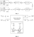
- a network structure composed of multiple Flex reconfigurable optical add-drop multiplexer (ROADM) sites exists in a network.
- FIG. 1 it illustrates a scenario that Long-span end-to-end traffic signal light penetrates cascaded ROADM sites in a transmission link.
- FIG. 2 both penetrating traffic light and add-drop traffic light at ROADM sites require cross-scheduling control by WSSs.
- the ROADM sites shown in FIG. 2 are typical two-dimensional ROADM site structures.
- WSSs in the straight-through direction of the ROADM sites cause filtering damage to the penetrating traffic light.
- a signal spectral bandwidth is close to a WSS channel bandwidth.
- the receptivity severely deteriorates after the absorption spectrum is filtered by cascaded WSSs. This is mainly because the high-frequency components of the spectrum are significantly suppressed after being filtered by the cascaded WSSs.
- a large error occurs in the phase detection in the clock extraction algorithm in the receiver, and the clock jitter or extraction failure leads to a positional deviation in data recovery. As a result, the transmission traffic is interrupted.
- Embodiments of the present invention provide a method and device for controlling the WSS channel attenuation parameter, a storage medium and a processor to solve at least the problem in which the performance of a receiver deteriorates after filtered optical signals enter the receiver because cascaded WSSs cause filtering damage to the optical signals in the related art. According to an embodiment of the present invention, a method for controlling the WSS channel attenuation parameter is provided.
- the method includes, for each WSS module in a cascaded WSS system, inputting white noise to the channel of each WSS module and adjusting the attenuation parameters of all slices of the channel according to a predefined rule such that the flatness of the output spectrum of the white noise is less than a first threshold; and calculating the average value of the adjusted attenuation parameters of the slices of a plurality of WSS modules and controlling the WSS channel attenuation parameter of each WSS module based on the average value.
- a device for controlling the WSS channel attenuation parameter includes an input module configured to, for each WSS module in a cascaded WSS system, input white noise to the channel of each WSS module; an adjustment module configured to adjust the attenuation parameters of all slices of the channel according to a predefined rule such that the flatness of the output spectrum of the white noise is less than a first threshold; and a control module configured to calculate the average value of the adjusted attenuation parameters of the slices of a plurality of WSS modules and control the WSS channel attenuation parameter of each WSS module based on the average value.
- a storage medium is provided.
- the storage medium includes a stored program. When the program is executed, the preceding power processing method is performed.
- a processor is provided.
- the processor is configured to execute the program.
- the program is executed, the preceding power processing method is performed.
- the following operations are performed for each WSS module in a cascaded WSS system: inputting white noise to the channel of each WSS module and adjusting the attenuation parameters of all slices of the channel according to a predefined rule such that the flatness of the output spectrum of the white noise is less than a first threshold; and calculating the average value of the adjusted attenuation parameters of the slices of a plurality of WSS modules and controlling the WSS channel attenuation parameter of each WSS module based on the average value.
- the preceding solution solves the problem in which the performance of a receiver deteriorates after filtered optical signals enter the receiver because cascaded WSSs cause filtering damage to the optical signals in the related art, thereby effectively reducing filtering damage when the optical signals pass through the cascaded WSSs and improving the performance of the receiver.
- FIG. 3 is a flowchart of the method for controlling the WSS channel attenuation parameter according to an embodiment of the present invention. As shown in FIG. 3 , the method includes the steps S302 and S304 below.
- step S302 for each WSS module in a cascaded WSS system, white noise is input to the channel of each WSS module and the attenuation parameters of all slices of the channel are adjusted according to a predefined rule such that the flatness of the output spectrum of the white noise is less than a first threshold.
- step S304 the average value of the adjusted attenuation parameters of the slices of a plurality of WSS modules is calculated and the WSS channel attenuation parameter of each WSS module is controlled based on the average value.
- each WSS module in a cascaded WSS system: inputting white noise to the channel of each WSS module and adjusting the attenuation parameters of all slices of the channel according to a predefined rule such that the flatness of the output spectrum of the white noise is less than a first threshold; and calculating the average value of the adjusted attenuation parameters of the slices of a plurality of WSS modules and controlling the WSS channel attenuation parameter of each WSS module based on the average value.
- Step S302 can be performed in multiple manners during the actual operation.
- One manner is provided in this embodiment of the present invention. The manner is described below.
- the attenuation parameters of all slices of the channel may be adjusted according to the predefined rule by using the solution below.
- the attenuation parameters of the secondary edge slices of all slices are adjusted so that a first adjustment result is obtained; the attenuation parameters of one or more center slices of the channel are adjusted based on the first adjustment result so that a second adjustment result is obtained; and then other slices of all slices excluding the secondary edge slices and the center slices are adjusted based on the first adjustment result and the second adjustment result. That is, in this embodiment of the present invention, the attenuation parameters of the secondary edge slices of all slices, the attenuation parameters of the center slices of all slices and the attenuation parameters of other slices of all slices may be adjusted in sequence.
- the attenuation parameters of the secondary edge slices of all slices may be adjusted preferably based on the baud rate of a traffic signal of the channel. That is, baud rate of the traffic signal of the channel are acquired and then the attenuation parameters of the secondary edge slices of all slices are adjusted based on the baud rate.
- the attenuation parameters of the secondary edge slices are adjusted such that the difference between the spectral height of the lowest spectral point corresponding to the secondary edge slices and the spectral height of f c - B/2 is less than a second threshold or such that the difference between the spectral height of the lowest spectral point corresponding to the secondary edge slices and the spectral height of f c + B/2 is less than the second threshold.
- f c denotes the central frequency of the channel.
- B denotes the baud rate of the traffic signal.
- the attenuation parameters of the center slices of the channel may be adjusted based on the first adjustment result of the attenuation parameters of the secondary edge slices by using the solution below.
- the attenuation parameters of one or more center slices of the channel are matched with the attenuation parameters of the secondary edge slices of the channel such that the flatness of the output spectrum of the white noise in segment f c - B/2 to f c or segment f c to f c - B/2 is less than the first threshold
- the adjusted attenuation parameters of one or more center slices are matched with the attenuation parameters of the secondary edge slices such that the flatness of the left half or the right half of the B long spectrum of the channel is less than the first threshold.
- Other slices of all slices excluding the secondary edge slices and the center slices are adjusted based on the first adjustment result and the second adjustment result in the manner below.
- the attenuation parameters of other slices are adjusted symmetrically according to the attenuation parameters of the secondary edge slices in the first adjustment result and the attenuation parameters of the center slices in the second adjustment result.
- the adjustment process for other slices is actually based on the adjustments to the secondary edge slices and the center slices. For example, in the case where there are currently 6 slices numbered 1, 2, 3, 4, 5 and 6 in sequence, first the attenuation parameter of secondary edge slice 2 is adjusted and then the attenuation parameter of center slice 3 is adjusted. Symmetrically, the attenuation parameter of slice 2 is mapped onto slice 5 on the right and the attenuation parameter of slice 3 is mapped onto slice 4 on the right.
- the attenuation parameters of first slices of all WSS modules are acquired separately and the average value of the attenuation parameters of the first slices of the all WSS modules is calculated.
- the attenuation parameters of second slices of all WSS modules to the attenuation parameter of N-th slices of all WSS module are acquired in sequence and the average value of the attenuation parameters of the second slices of the all WSS modules to the average value of the attenuation parameters of the N-th slices of the all WSS modules are calculated.
- the average value of the attenuation parameters of the first slices of the all WSS modules, the average value of the attenuation parameters of the second slices of the all WSS modules, ..., and the average value of the attenuation parameters of the N-th slices of the all WSS modules are calculated in sequence, and then the first slices of the WSS modules, the second slices of the WSS modules, ..., and the N-th slices of the WSS modules in the cascaded WSS system are adjusted in sequence based on the obtained averages.
- This example of the present invention describes a method and system for improving the performance of long-distance 100G/B100G quasi-Nyquist WDM transmission in a cascaded Flex ROADM system.
- a frequency spacing between channels is close to the baud rate of traffic light. That is, quasi-Nyquist WDM transmission is implemented.
- 100G PM-QPSK and 200G PM-16QAM traffic signals having a baud rate of about 34 GHz are transmitted in a channel spacing of 37.5 GHz
- 200G PM-8QAM traffic signals having a baud rate of about 45 GHz are transmitted in a channel spacing of 50 GHz.
- a service transceiver in the system uses a coherent receiver optical module.
- the DSP clock synchronization algorithm at the receiving end of the optical module extracts a clock component from signal light.
- Penetration of cascading WSSs exist in the end-to-end transmission link of traffic light in the system.
- the WSSs include WSS units for optical add multiplexing, WSS units for optical drop demultiplexing and WSS units in the bypass direction of ROADM sites.
- the frequency adjustment granularity supported by the WSS units of the system is significantly smaller than the channel spacing.
- the corresponding smallest adjustable frequency gird is 12.5 GHz, 6.25 GHz or 3.125 GHz.
- this example of the present invention further provides a WSS spectrum shaping unit having adjustable attenuation within the bandwidth.
- This unit uses a slice attenuation control method for multiple slices (which may be understood as the slices in this embodiment) in a channel. The method includes the steps below. 1. First, the WSS channel attenuation parameter of the secondary edge slices of a channel is adjusted based on the baud rate of a traffic signal.
- the WSS channel attenuation parameter of each slice in the bandwidth of the channel is set to 0 before the WSS channel attenuation parameters of the secondary edge slices of the channel are adjusted.
- the WSS channel attenuation parameter of the secondary edge slices of the channel is adjusted such that the spectral height of the lowest spectral point corresponding to the secondary edge slices is close to the spectral height of f c ⁇ B/2.
- f c denotes the central frequency of the channel.
- B denotes the baud rate of the traffic signal.
- the WSS channel attenuation parameter of the center slices of the channel is adjusted based on the flatness of the channel.
- the same synchronous attenuation adjustment is made to one or more slices at the center of the channel.
- the WSS channel attenuation parameter of the center slices is adapted to the WSS channel attenuation parameter of the secondary edge slices so that the spectrum in segment f c - B/2 to f c is approximately flat. 3.
- the WSS channel attenuation parameter of various slices of the channel is adjusted symmetrically about the center of the channel.
- the attenuation parameter of various slices of the channel is adjusted symmetrically about the center of the channel, the attenuation parameter of the slices at the outermost edge of the channel is zero.
- the spectrum shape of the channel remains symmetrical, and the spectrum in segment f c - B/2 to f c + B/2 is approximately flat, that is, the difference between the central frequency component and the edge frequency component in the channel is relatively reduced.
- the channel shaping parameters (that is, the attenuation parameters adjusted in the preceding steps 1, 2, and 3) of the penetrated WSS units in this traffic configuration are obtained.
- traffic is established in a cascaded WSS system, it is feasible to configure the channel shaping parameters for the WSS units at optical multiplexing, optical demultiplexing and ROADM penetration points in a transmission link and perform traffic spectrum shaping for each stage of WSS unit.
- wide-spectrum white noise (which may be understood as the white noise of this embodiment) is connected to the input end of each WSS unit and the output spectrum shape is monitored by a spectrum analyzer at the output end of each WSS unit. Such operation is performed for feedback adjustment of the WSS channel attenuation parameter.
- additional attenuation adjustment (for the effect, see FIG. 9 ) of the spectral center spectral component of each WSS unit is performed using the spectrum shaping method of WSS slice attenuation control.
- Such operation helps reduce the difference between the central frequency component and the edge frequency component caused by WSS filtering and ensures that the clock synchronization algorithm at the receiving end effectively extracts the clock from the high-frequency component of a signal, thereby improving the reliable receptivity of the 100G/B 100G coherent receiver after cascaded WSSs are cascaded.
- spectrum shaping at each WSS unit in an optical link helps suppress the filtering effect of each WSS, overcome the problem of limited WSS penetration level caused by insufficient pre-emphasis capability of the optical transceiver, and significantly improve the penetration capability of cascaded WSSs of the optical transceiver.
- the shaping parameter configuration of this example of the present invention ensures that each WSS uses the same shaping parameter that is not dynamically adjusted as the stage of each WSS unit in an optical link is changed, helping reducing the end-to-end link detection of traffic light at the network control level and the feedback control of the pre-emphasis parameters of an optical transceiver.
- the implementation method is simple and low in cost since it is feasible simply to perform SLICE-level software control and adjustment of units whose WSS bandwidth attenuation is adjustable and not to add additional optical devices in a transmission link.
- WSS channels and channels mentioned in this embodiment and this example of the present invention may have the same meaning.
- these channels are all WSS channels or are all channels.
- these channels may have different meanings. This is not limited in this embodiment of the present invention.
- the method of the preceding embodiment may be implemented by software plus a necessary general-purpose hardware platform or may, of course, be implemented by hardware. However, in many cases, the former is a preferred implementation.
- the solution of the present invention substantially, or the part contributing to the existing art, may be embodied in the form of a software product.
- the software product is stored in a storage medium (such as a ROM/RAM, a magnetic disk or an optical disk) and includes several instructions for enabling a terminal (which may be a mobile phone, a computer, a server or a network device) to execute the method of each embodiment of the present invention.
- a device for controlling the WSS channel attenuation parameter is provided.
- the device is configured to implement the preceding embodiment and preferred implementations. What has been described will not be repeated.
- the term "module" may be software, hardware or a combination thereof capable of implementing predetermined functions.
- the device in this embodiment is preferably implemented by software, but implementation by hardware or by a combination of software and hardware is also possible and conceived.
- FIG. 5 is a block diagram illustrating the structure of the device for controlling the WSS channel attenuation parameter according to an embodiment of the present invention.
- the device includes an input module 50, an adjustment module 52 and a control module 54.
- the input module 50 is configured to, for each WSS module in a cascaded WSS system, input white noise to the channel of each WSS module.
- the adjustment module 52 is configured to adjust the attenuation parameters of all slices of the channel according to a predefined rule such that the flatness of the output spectrum of the white noise is less than a first threshold.
- the control module 54 is configured to calculate the average value of the adjusted attenuation parameters of the slices of a plurality of WSS modules and control the WSS channel attenuation parameter of each WSS module based on the average value.
- each WSS module in a cascaded WSS system: inputting white noise to the channel of each WSS module and adjusting the attenuation parameters of all slices of the channel according to a predefined rule such that the flatness of the output spectrum of the white noise is less than a first threshold; and calculating the average value of the adjusted attenuation parameters of the slices of all WSS modules and controlling the WSS channel attenuation parameter of each WSS module based on the average value.
- the preceding solution solves the problem in which the performance of a receiver deteriorates after filtered optical signals enter the receiver because cascaded WSSs cause filtering damage to the optical signals in the related art, thereby effectively reducing filtering damage when the optical signals pass through the cascaded WSSs and improving the performance of the receiver.
- FIG. 6 is a block diagram illustrating the structure of the adjustment module 52 of the device for controlling the WSS channel attenuation parameter according to this embodiment of the present invention.
- the adjustment module 52 includes a first adjustment unit 520, a second adjustment unit 522 and a third adjustment unit 524.
- the first adjustment unit 520 is configured to adjust the attenuation parameters of the secondary edge slices of all slices to obtain a first adjustment result.
- the second adjustment unit 522 is configured to adjust the attenuation parameters of one or more center slices of the channel based on the first adjustment result to obtain a second adjustment result.
- the third adjustment unit 524 is configured to adjust other slices of all slices excluding the secondary edge slices and the center slices based on the first adjustment result and the second adjustment result. That is, in this embodiment of the present invention, the attenuation parameters of the secondary edge slices of all slices, the attenuation parameters of the center slices of all slices and the attenuation parameters of other slices of all slices may be adjusted in sequence. As shown in FIG. 6 , the first adjustment unit 520 is further configured to acquire the baud rate of a traffic signal of the channel; and adjust the attenuation parameters of the secondary edge slices of all slices based on the baud rate.
- the first adjustment unit 520 is further configured to adjust the attenuation parameters of the secondary edge slices such that the difference between the spectral height of the lowest spectral point corresponding to the secondary edge slices and the spectral height of f c - B/2 is less than a second threshold or such that the difference between the spectral height of the lowest spectral point corresponding to the secondary edge slices and the spectral height of f c + B/2 is less than the second threshold.
- f c denotes the central frequency of the channel.
- B denotes the baud rate of the traffic signal.
- the second adjustment unit 522 is further configured to match the attenuation parameters of one or more center slices of the channel with the attenuation parameters of the secondary edge slices such that the flatness of the output spectrum of the white noise in segment f c - B/2 to f c or segment f c to f c - B/2 is less than the first threshold.
- the third adjustment unit 524 is configured to adjust the attenuation parameters of other slices symmetrically by taking the central frequency f c of the channel as the central axis according to the attenuation parameters of the secondary edge slices in the first adjustment result and the attenuation parameters of the center slices in the second adjustment result.
- FIG. 7 is a block diagram illustrating the structure of the adjustment module 52 of the device for controlling the WSS channel attenuation parameter according to this embodiment of the present invention.
- the control module 54 includes a first processing unit 540 and a second processing unit 542.
- the first processing unit 540 is configured to acquire the attenuation parameters of first slices of all WSS modules separately and calculate the average value of the attenuation parameters of the first slices of the all WSS modules.
- the second processing unit 542 is configured to acquire the attenuation parameters of second slices of the all WSS modules to the attenuation parameters of the N-th slices of the all WSS modules in sequence and calculate the average value of the attenuation parameters of the second slices of the all WSS modules to the average value of the attenuation parameters of the N-th slices of the all WSS modules.
- the average value of the attenuation parameters of the first slices of all WSS modules, the average value of the attenuation parameters of the second slices of all WSS modules, ..., and the average value of the attenuation parameters of the N-th slices of all WSS modules are calculated in sequence, and then the first slices of the WSS modules, the second slices of the WSS modules, ..., and the N-th slices of the WSS modules in the cascaded WSS system are adjusted in sequence based on the obtained averages.
- preceding modules may be implemented by software or hardware. Implementation by hardware may, but not necessarily, be performed in the following manner: the preceding modules are located in the same processor or the preceding modules are located in any combination in their respective processors.
- one of the present invention provides a method for adjusting attenuation in a WSS channel bandwidth. This method is applied to the scenario where 100G QPSK/200G 16 quadrature amplitude modulation (QAM) optical signals pass through cascaded WSSs in a channel bandwidth of 37.5 GHz.
- FIG. 8 shows the steps of adjusting the WSS channel attenuation parameter of 6 ⁇ 6.25 GHz slices in the WSS channel (which may be understood as the channel mentioned in the preceding embodiments) bandwidth. The steps are described below.
- step 1 wide-spectrum white noise is input to a single WSS unit, the central frequency and channel bandwidth of the WSS unit are set, the output end of the WSS unit is connected to a spectrum analyzer, the WSS channel bandwidth is set to 37.5 GHz, and the six 6.25 GHz slices are configured with the same WSS channel attenuation parameter.
- the output spectrum shape in this case is shown in FIG. 8 .
- step 2 the central frequency f c of the output spectrum is found, and the two horizontal frequency calibration lines of the spectrum analyzer are adjusted to f c - B 1 /2 and f c + B 1 /2 based on the baud rate B 1 of a traffic transceiver module, for example, a baud rate B 1 of about 34 Gbaud of both a 100G PM-QPSK traffic module with 25% FEC overhead and a 200G PM-16QAM traffic module with 25% FEC overhead.
- step 3 the WSS channel attenuation parameter of secondary edge slice 2 in the WSS channel bandwidth is adjusted such that the spectral height of the lowest spectral point f 2 in segment f c -B 1 /2 to f c is close to the spectral height of f c - B 1 /2.
- the adjusted output spectrum is shown in FIG. 8 .
- step 4 the WSS channel attenuation parameter of center slice 3 in the WSS channel bandwidth is adjusted such that the spectrum in segment f c - B 1 /2 to f c is approximately flat, or more specifically, the flatness of the channel in this segment does not exceed 0.4 dB.
- the adjusted output spectrum is shown in FIG. 8 .
- step 5 the WSS channel attenuation parameter of slice 4 and the WSS channel attenuation parameter of slice 5 in the WSS channel bandwidth are adjusted symmetrically about the center of the channel, that is, the WSS channel attenuation parameter of slice 4 and the WSS channel attenuation parameter of slice 5 are set to the same as the WSS channel attenuation parameter of slice 2 and the WSS channel attenuation parameter of slice 3 respectively.
- the adjusted WSS channel attenuation parameter of the six 6.25 GHz slices is symmetrical about the central frequency f c .
- the corresponding output spectrum is also symmetrical.
- the adjusted output spectrum is shown in FIG. 5 . In this case, the attenuation adjustment parameters of the WSS unit are obtained.
- step 6 in view of little difference between WSSs, N (which is not less than 3) WSS modules are selected, steps 3 to 5 are performed repeatedly for the selected N modules so that the attenuation parameters of the slices of the WSS modules are acquired in sequence, the average value of the N attenuation parameters of the individual slices of the WSS modules is calculated separately, and finally the average is used as the attenuation configuration parameter of a corresponding slice in the WSS channel bandwidth.
- one of the present invention provides a method for shaping in a WSS channel bandwidth of 37.5 GHz.
- the WSS channel attenuation parameter of each slice is adjusted according to the serial number of the each slice. It is also feasible to perform the symmetrical adjustment of step 5 in a different sequence. That is, it is feasible to adjust secondary slices 2 and 5 and then adjust center slices 3 and 4 as long as the obtained channel attenuation parameters are the same in the two adjustment sequences.
- This method for shaping in a WSS channel bandwidth of 37.5 GHz is applied to the penetration scenario where 100G QPSK/200G 16QAM signals pass through cascaded WSSs.
- the system configures the WSS channel attenuation parameter for the six 6.25 GHz slices of the WSS unit in the 37.5 GHz channel bandwidth.
- the method of this preferred embodiment suppresses the difference between the central frequency component and the edge frequency component caused by filtering of cascaded WSSs and ensures that the clock synchronization algorithm at the receiving end effectively extracts the clock component, thereby improving the receptivity of an optical transceiver.
- Preferred embodiment two of the present invention provides a method for adjusting attenuation in a WSS channel bandwidth. This method is applied to the scenario where 200G PM-8QAM optical signals pass through cascaded WSSs in a channel bandwidth of 50 GHz. The steps of adjusting the WSS channel attenuation parameter of 8 ⁇ 6.25 GHz slices in the WSS channel bandwidth are described below.
- step 1 wide-spectrum white noise is input to a single WSS unit, the central frequency and channel bandwidth of the WSS unit are set, the output end of the WSS unit is connected to a spectrum analyzer, the WSS channel bandwidth is set to 50 GHz, and the eight slices are configured with the same WSS channel attenuation parameter. For ease of description, it is assumed that the eight slices in the 50 GHz WSS channel bandwidth are numbered 1 to 8 in sequence.
- step 2 the central frequency f c of the output spectrum is found, and the two horizontal frequency calibration lines of the spectrum analyzer are adjusted to f c - B 2 /2 and f c + B 2 /2 based on the baud rate B 2 of a traffic transceiver module, for example, a baud rate B 2 of about 45 Gbaud of a 200G PM-8QAM traffic module with 25% FEC overhead.
- step 3 the WSS channel attenuation parameter of secondary edge slice 2 in the WSS channel bandwidth is adjusted such that the spectral height of the lowest spectral point in segment f c - B 2 /2 to f c is close to the spectral height of f c - B 2 /2.
- step 4 the WSS channel attenuation parameter of center slices 3 and 4 in the WSS channel bandwidth is adjusted and the same adjustment is made to attenuation of two slices in the center such that the spectrum in segment f c - B 2 /2 to f c is approximately flat, or more specifically, the flatness of the channel in this segment does not exceed 0.4 dB.
- step 5 the WSS channel attenuation parameter of slices 5, 6 and 7 in the channel bandwidth is adjusted symmetrically about the center of the channel.
- the adjusted WSS channel attenuation parameter of the eight slices is symmetrical about the central frequency f c .
- the attenuation adjustment parameters of the WSS unit are obtained.
- step 6 N WSS modules are selected, the attenuation parameters of the slices of the WSS modules are acquired in sequence, the average value of the N attenuation parameters of the individual slices of the WSS modules is calculated separately, and the average is used as the attenuation configuration amount of a corresponding slice in the WSS channel bandwidth.
- this preferred embodiment of the present invention provides a method for shaping in a WSS channel bandwidth of 50 GHz.
- the WSS channel attenuation parameter of each slice is adjusted according to the serial number of the each slice. It is also feasible to perform the symmetrical adjustment of step 5 in a different sequence. That is, it is feasible to adjust secondary slices 2 and 7 and then adjust center slices 3 to 6 as long as the obtained channel attenuation parameters are the same in the two adjustment sequences.
- This method for shaping in a WSS channel bandwidth of 50 GHz is applied to the penetration scenario where 200G 8QAM signals pass through cascaded WSSs.
- the system configures the WSS channel attenuation parameter for the eight 6.25 GHz slices of the WSS unit in the 50 GHz channel bandwidth. Based on a spectrum shaping method for attenuation control in a WSS bandwidth, the method of this preferred embodiment improves the receptivity of an optical transceiver in a cascaded WSS system.
- Preferred embodiment three of the present invention provides a method for adjusting attenuation in a WSS channel bandwidth. This method is applied to the scenario where 200G PM-QPSK optical signals pass through cascaded WSSs in a channel bandwidth of 75 GHz. The steps of adjusting the WSS channel attenuation parameter of 12 ⁇ 6.25 GHz slices in the WSS channel bandwidth are described below.
- step 1 wide-spectrum white noise is input to a single WSS unit, the central frequency and channel bandwidth of the WSS unit are set, the output end of the WSS unit is connected to a spectrum analyzer, the WSS channel bandwidth is set to 75 GHz, and the 12 slices are configured with the same WSS channel attenuation parameter. For ease of description, it is assumed that the 12 slices in the 75 GHz WSS channel bandwidth are numbered 1 to 12 in sequence.
- step 2 the central frequency f c of the output spectrum is found, and the two horizontal frequency calibration lines of the spectrum analyzer are adjusted to f c - B 3 /2 and f c + B3/2 based on the baud rate B 3 of a traffic transceiver module, for example, a baud rate B 3 of about 68 Gbaud of a 200G PM-QPSK traffic module with 25% FEC overhead.
- step 3 the WSS channel attenuation parameter of secondary edge slice 2 in the WSS channel bandwidth is adjusted such that the spectral height of the lowest spectral point in segment f c - B 3 /2 to f c is close to the spectral height of f c - B 3 /2.
- step 4 the WSS channel attenuation parameter of center slices 3, 4, 5 and 6 in the WSS channel bandwidth is adjusted and the same adjustment is made to attenuation of four slices in the center such that the spectrum in segment f c - B 3 /4 to f c is approximately flat, or more specifically, the flatness of the channel in this segment does not exceed 0.4 dB.
- step 5 the WSS channel attenuation parameter of slices 7, 8, 9, 10 and 11 in the channel bandwidth is adjusted symmetrically about the center of the channel.
- the adjusted WSS channel attenuation parameter of the 12 slices is symmetrical about the central frequency f c .
- the attenuation adjustment parameters of the WSS unit are obtained.
- step 6 N WSS modules are selected, the attenuation parameters of the slices of the WSS modules are acquired in sequence, the average value of the N attenuation parameters of the individual slices of the WSS modules is calculated separately, and the average is used as the attenuation configuration parameter of a corresponding slice in the WSS channel bandwidth.
- preferred embodiment three of the present invention provides a method for shaping in a WSS channel bandwidth of 75 GHz.
- the WSS channel attenuation parameter of each slice is adjusted according to the serial number of the each slice. It is also feasible to perform the symmetrical adjustment of step 5 in a different sequence. That is, it is feasible to adjust secondary slices 2 and 11 and then adjust center slices 3 to 10 as long as the obtained channel attenuation parameters are the same in the two adjustment sequences.
- This method for shaping in a WSS channel bandwidth of 75 GHz is applied to the penetration scenario where 200G PM-QPSK signals pass through cascaded WSSs.
- the system configures the WSS channel attenuation parameter for the 12 6.25 GHz slices of the WSS unit in the 75 GHz channel bandwidth. Based on a spectrum shaping method for attenuation control in a WSS bandwidth, the method of this preferred embodiment improves the receptivity of an optical transceiver in a cascaded WSS system.
- Preferred embodiment four of the present invention provides a filtering performance optimization method based on WSS slice control.
- This WSS slice control method uses a finer spectral granularity.
- the minimum adjustable spectral granularity is 3.125 GHz.
- this method further improves the spectral flatness and the receptivity of an optical transceiver after cascaded WSSs are cascaded.
- the steps of adjusting the WSS channel attenuation parameter of 12 ⁇ 3.125 GHz slices in the WSS channel bandwidth are described below by using 100G PM-QPSK as an example.
- step 1 wide-spectrum white noise is input to a single WSS unit, the central frequency and channel bandwidth of the WSS unit are set, the output end of the WSS unit is connected to a spectrum analyzer, the WSS channel bandwidth is set to 37.5 GHz, and the 12 slices are configured with the same WSS channel attenuation parameter. For ease of description, it is assumed that the 12 slices in the 37.5 GHz WSS channel bandwidth are numbered 1 to 12 in sequence.
- step 2 the central frequency f c of the output spectrum is found, and the two horizontal frequency calibration lines of the spectrum analyzer are adjusted to f c - B 1 /2 and f c + B 1 /2 based on the baud rate B 1 of a traffic transceiver module.
- step 3 the WSS channel attenuation parameter of secondary edge slice 2 in the WSS channel bandwidth is adjusted such that the spectral height of the lowest spectral point in segment f c - B 1 /2 to f c is close to the spectral height of f c - B 1 /2.
- step 4 the WSS channel attenuation parameter of center slices 3, 4, 5 and 6 in the WSS channel bandwidth is adjusted and the same adjustment is made to attenuation of four slices in the center such that the spectrum in segment f c - B 1 /2 to f c is approximately flat, or more specifically, the flatness of the channel in this segment does not exceed 0.4 dB.
- step 5 the WSS channel attenuation parameter of slices 7, 8, 9, 10 and 11 in the channel bandwidth is adjusted symmetrically about the center of the channel.
- the adjusted WSS channel attenuation parameter of the 12 slices is symmetrical about the central frequency f c .
- the attenuation adjustment parameters of the WSS unit are obtained.
- step 6 N WSS modules are selected, the attenuation parameters of the slices of the WSS modules are acquired in sequence, the average value of the N attenuation parameters of the individual slices of the WSS modules is calculated separately, and the average is used as the attenuation configuration parameter of a corresponding slice in the WSS channel bandwidth.
- preferred embodiment four of the present invention provides a method for shaping in a WSS channel bandwidth of 37.5 GHz.
- the WSS channel attenuation parameter of each slice is adjusted according to the serial number of the each slice. It is also feasible to perform the symmetrical adjustment of step 5 in a different sequence. That is, it is feasible to adjust secondary slices 2 and 11 and then adjust center slices 3 to 10 as long as the obtained channel attenuation parameters are the same in the two adjustment sequences.
- This method for shaping in a WSS channel bandwidth of 37.5GHz is applied to the penetration scenario where 200G PM-QPSK signals pass through cascaded WSSs.
- the system configures the WSS channel attenuation parameter for the 12 3.125 GHz slices of the WSS unit in the 37.5 GHz channel bandwidth.
- the number of adjustable slices in a bandwidth varies with the traffic type corresponding to the bandwidth. The method involved is the same as described earlier and will not be repeated here.
- This spectrum shaping method based on WSS with a finer adjustable spectral granularity improves the flatness of a WSS channel and thereby further improves the receptivity of an optical transceiver in a cascaded WSS system.
- An embodiment of the present invention provides a storage medium.
- the storage medium includes a stored program. When the program is executed, the method of any one of the preceding embodiments is performed.
- the storage medium may be configured to store program codes for performing the steps below.
- the average value of the adjusted attenuation parameters of the slices of a plurality of WSS modules is calculated and the WSS channel attenuation parameter of each WSS module is controlled based on the average value.
- the storage medium is further configured to store program codes for performing the steps below.
- the attenuation parameters of one or more center slices of the channel are adjusted based on the first adjustment result so that a second adjustment result is obtained.
- the storage medium may include, but is not limited to, a U disk, a read-only memory (ROM), a random access memory (RAM), a mobile hard disk, a magnetic disk, an optical disk or another medium capable of storing program codes.
- modules or steps in embodiments of the present invention may be implemented by a general-purpose computing device and may be concentrated on a single computing device or distributed in a network formed by multiple computing devices.
- these modules or steps may be implemented by program codes executable by the computing device.
- these modules or steps may be stored in a storage device and executed by the computing device.
- the illustrated or described steps may be executed in a sequence different from the sequence described herein.
- each module or step may be implemented by being made into an integrated circuit module separately or multiple ones of these modules or steps may be implemented by being made into a single integrated circuit module. In this manner, the present invention is not limited to any specific combination of hardware and software.
- the method and device for controlling the WSS channel attenuation parameter, the storage medium and the processor provided in embodiments of the present invention have the following beneficial effects:
- the problem is solved in which the performance of a receiver deteriorates after filtered optical signals enter the receiver because cascaded WSSs cause filtering damage to the optical signals in the related art. Filtering damage is effectively reduced when the optical signals pass through the cascaded WSSs. Thus, the performance of the receiver is improved.
Landscapes
- Engineering & Computer Science (AREA)
- Computer Networks & Wireless Communication (AREA)
- Signal Processing (AREA)
- Physics & Mathematics (AREA)
- Electromagnetism (AREA)
- Spectroscopy & Molecular Physics (AREA)
- Optical Communication System (AREA)
Abstract
Description
- The present invention relates to the field of communications and, in particular, to a method and device for controlling a wavelength-selective switch (WSS) channel attenuation parameter, a device, a storage medium and a processor.
- An existing Dense Wavelength Division Multiplexing (DWDM) system mostly adopts a channel spacing of 50 GHz or 100 GHz and thus is actually a fixed-grid Wavelength Division Multiplexing (WDM) system. With the development of ultra-high-speed 100G/B100G WDM transmission network and Automatically Switched Optical Network (ASON)/Software Defined Optical Network (SDON) technologies, a traditional WDM system is facing challenges in spectrum utilization and flexibility, and a demand is created for a flexible-grid WDM system that supports different channel spacings and transmission rates and has a channel spacing dynamically settable as desired.
- The Flexible Grid technology was first standardized by the International Telecommunication Union-T (ITU-T) G.694.1 standard in 2011. In the standard, the nominal central frequencies of normative frequency slots are 193.1 THz + n × 6.25 GHz. The current mainstream WSS manufacturers all introduce WSS modules having a channel spacing of 12.5 GHz or 6.25 GHz, which achieves the quasi-Nyquist WDM transmission scheme having a higher spectral efficiency. For example, 100G Polarization Multiplexed Quadrature Phase Shift Keying (PM-QPSK) traffic optical signals (containing 25% forward error correction (FEC) overhead) having a baud rate of about 34 Gbaud are transmitted in channels having a channel spacing of 37.5 GHz. This method can further reduce channel spacings of a WDM system, thereby improving the spectral efficiency of the C-band in an optical fiber system and expanding the system transmission capacity. Nevertheless, in a practical engineering application, a network structure composed of multiple Flex reconfigurable optical add-drop multiplexer (ROADM) sites exists in a network. As shown in
FIG. 1 , it illustrates a scenario that Long-span end-to-end traffic signal light penetrates cascaded ROADM sites in a transmission link. As shown inFIG. 2 , both penetrating traffic light and add-drop traffic light at ROADM sites require cross-scheduling control by WSSs. The ROADM sites shown inFIG. 2 are typical two-dimensional ROADM site structures. WSSs in the straight-through direction of the ROADM sites cause filtering damage to the penetrating traffic light. Particularly in the quasi-Nyquist WDM scheme, a signal spectral bandwidth is close to a WSS channel bandwidth. In this manner, the receptivity severely deteriorates after the absorption spectrum is filtered by cascaded WSSs. This is mainly because the high-frequency components of the spectrum are significantly suppressed after being filtered by the cascaded WSSs. Thus, a large error occurs in the phase detection in the clock extraction algorithm in the receiver, and the clock jitter or extraction failure leads to a positional deviation in data recovery. As a result, the transmission traffic is interrupted. - No effective solution has been proposed to address the problem in which the performance of a receiver deteriorates after filtered optical signals enter the receiver because cascaded WSSs cause filtering damage to the optical signals in the related art.
- Embodiments of the present invention provide a method and device for controlling the WSS channel attenuation parameter, a storage medium and a processor to solve at least the problem in which the performance of a receiver deteriorates after filtered optical signals enter the receiver because cascaded WSSs cause filtering damage to the optical signals in the related art. According to an embodiment of the present invention, a method for controlling the WSS channel attenuation parameter is provided. The method includes, for each WSS module in a cascaded WSS system, inputting white noise to the channel of each WSS module and adjusting the attenuation parameters of all slices of the channel according to a predefined rule such that the flatness of the output spectrum of the white noise is less than a first threshold; and calculating the average value of the adjusted attenuation parameters of the slices of a plurality of WSS modules and controlling the WSS channel attenuation parameter of each WSS module based on the average value.
- According to another embodiment of the present invention, a device for controlling the WSS channel attenuation parameter is provided. The device includes an input module configured to, for each WSS module in a cascaded WSS system, input white noise to the channel of each WSS module; an adjustment module configured to adjust the attenuation parameters of all slices of the channel according to a predefined rule such that the flatness of the output spectrum of the white noise is less than a first threshold; and a control module configured to calculate the average value of the adjusted attenuation parameters of the slices of a plurality of WSS modules and control the WSS channel attenuation parameter of each WSS module based on the average value. According to another embodiment of the present invention, a storage medium is provided. The storage medium includes a stored program. When the program is executed, the preceding power processing method is performed.
- According to another embodiment of the present invention, a processor is provided. The processor is configured to execute the program. When the program is executed, the preceding power processing method is performed.
- Through embodiments of the present invention, the following operations are performed for each WSS module in a cascaded WSS system: inputting white noise to the channel of each WSS module and adjusting the attenuation parameters of all slices of the channel according to a predefined rule such that the flatness of the output spectrum of the white noise is less than a first threshold; and calculating the average value of the adjusted attenuation parameters of the slices of a plurality of WSS modules and controlling the WSS channel attenuation parameter of each WSS module based on the average value. The preceding solution solves the problem in which the performance of a receiver deteriorates after filtered optical signals enter the receiver because cascaded WSSs cause filtering damage to the optical signals in the related art, thereby effectively reducing filtering damage when the optical signals pass through the cascaded WSSs and improving the performance of the receiver.
- The drawings described herein are used to provide a further understanding of the present invention and form a part of the present application. The illustrative embodiments and the description thereof in the present invention are used to explain the present invention and not to limit the present invention improperly. In the drawings:
-
FIG. 1 is a block diagram of a unidirectional DWDM Flex ROADM network in the related art; -
FIG. 2 is a block diagram illustrating the internal structure of ROADM sites in the related art; -
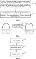
FIG. 3 is a flowchart of a method for controlling the WSS channel attenuation parameter according to an embodiment of the present invention; -
FIG. 4 is a schematic diagram of pre-emphasis of an optical transmitter according to an embodiment of the present invention; -
FIG. 5 is a block diagram illustrating the structure of a device for controlling the WSS channel attenuation parameter according to an embodiment of the present invention; -
FIG. 6 is a block diagram illustrating the structure of theadjustment module 52 of a device for controlling the WSS channel attenuation parameter according to an embodiment of the present invention; -
FIG. 7 is a block diagram illustrating the structure of theadjustment module 52 of a device for controlling the WSS channel attenuation parameter according to an embodiment of the present invention; -
FIG. 8 is a flowchart for adjusting attenuation parameters according to a preferred embodiment of the present invention; and -
FIG. 9 is a schematic diagram illustrating WSS-slice-level spectrum shaping according to an embodiment of the present invention. - Hereinafter, the present invention will be described in detail with reference to drawings and in conjunction with embodiments. It is to be noted that if not in collision, the embodiments described herein and the features in the embodiments may be combined with each other.
- It is to be noted that the terms such as "first" and "second" in the description, claims and drawings of the present invention are used to distinguish between similar objects and are not necessarily used to describe a particular order or sequence.
- This embodiment provides a method for controlling the WSS channel attenuation parameter.
FIG. 3 is a flowchart of the method for controlling the WSS channel attenuation parameter according to an embodiment of the present invention. As shown inFIG. 3 , the method includes the steps S302 and S304 below. - In step S302, for each WSS module in a cascaded WSS system, white noise is input to the channel of each WSS module and the attenuation parameters of all slices of the channel are adjusted according to a predefined rule such that the flatness of the output spectrum of the white noise is less than a first threshold.
- In step S304, the average value of the adjusted attenuation parameters of the slices of a plurality of WSS modules is calculated and the WSS channel attenuation parameter of each WSS module is controlled based on the average value.
- Through the preceding steps, the following operations are performed for each WSS module in a cascaded WSS system: inputting white noise to the channel of each WSS module and adjusting the attenuation parameters of all slices of the channel according to a predefined rule such that the flatness of the output spectrum of the white noise is less than a first threshold; and calculating the average value of the adjusted attenuation parameters of the slices of a plurality of WSS modules and controlling the WSS channel attenuation parameter of each WSS module based on the average value. The preceding solution solves the problem in which the performance of a receiver deteriorates after filtered optical signals enter the receiver because cascaded WSSs cause filtering damage to the optical signals in the related art, thereby effectively reducing filtering damage when the optical signals pass through the cascaded WSSs and improving the performance of the receiver. Step S302 can be performed in multiple manners during the actual operation. One manner is provided in this embodiment of the present invention. The manner is described below.
- The attenuation parameters of all slices of the channel may be adjusted according to the predefined rule by using the solution below.
- The attenuation parameters of the secondary edge slices of all slices are adjusted so that a first adjustment result is obtained; the attenuation parameters of one or more center slices of the channel are adjusted based on the first adjustment result so that a second adjustment result is obtained; and then other slices of all slices excluding the secondary edge slices and the center slices are adjusted based on the first adjustment result and the second adjustment result. That is, in this embodiment of the present invention, the attenuation parameters of the secondary edge slices of all slices, the attenuation parameters of the center slices of all slices and the attenuation parameters of other slices of all slices may be adjusted in sequence.
- Based on the preceding solution, the detailed solution provided in this embodiment of the present invention is described below as to how to adjust the secondary edge slices, center slices and other slices of all slices. (1) The attenuation parameters of the secondary edge slices of all slices may be adjusted preferably based on the baud rate of a traffic signal of the channel. That is, baud rate of the traffic signal of the channel are acquired and then the attenuation parameters of the secondary edge slices of all slices are adjusted based on the baud rate.
- Further, the attenuation parameters of the secondary edge slices are adjusted such that the difference between the spectral height of the lowest spectral point corresponding to the secondary edge slices and the spectral height of fc - B/2 is less than a second threshold or such that the difference between the spectral height of the lowest spectral point corresponding to the secondary edge slices and the spectral height of fc + B/2 is less than the second threshold. fc denotes the central frequency of the channel. B denotes the baud rate of the traffic signal. (2) The attenuation parameters of the center slices of the channel may be adjusted based on the first adjustment result of the attenuation parameters of the secondary edge slices by using the solution below.
- That the attenuation parameters of one or more center slices of the channel are matched with the attenuation parameters of the secondary edge slices of the channel such that the flatness of the output spectrum of the white noise in segment fc - B/2 to fc or segment fc to fc - B/2 is less than the first threshold may be understood as that in this embodiment of the present invention, the adjusted attenuation parameters of one or more center slices are matched with the attenuation parameters of the secondary edge slices such that the flatness of the left half or the right half of the B long spectrum of the channel is less than the first threshold. (3) Other slices of all slices excluding the secondary edge slices and the center slices are adjusted based on the first adjustment result and the second adjustment result in the manner below.
- By taking the central frequency fc of the channel as the central axis, the attenuation parameters of other slices are adjusted symmetrically according to the attenuation parameters of the secondary edge slices in the first adjustment result and the attenuation parameters of the center slices in the second adjustment result. The adjustment process for other slices is actually based on the adjustments to the secondary edge slices and the center slices. For example, in the case where there are currently 6 slices numbered 1, 2, 3, 4, 5 and 6 in sequence, first the attenuation parameter of
secondary edge slice 2 is adjusted and then the attenuation parameter ofcenter slice 3 is adjusted. Symmetrically, the attenuation parameter ofslice 2 is mapped ontoslice 5 on the right and the attenuation parameter ofslice 3 is mapped ontoslice 4 on the right. The preceding can be understood as symmetry from the left to the right. During the actual operation, symmetry from the right to the left is also feasible. This is not limited in this embodiment of the present invention. In addition, in this embodiment of the present invention, a manner is provided as below for calculating the average value described in step S304. - The attenuation parameters of first slices of all WSS modules are acquired separately and the average value of the attenuation parameters of the first slices of the all WSS modules is calculated. The attenuation parameters of second slices of all WSS modules to the attenuation parameter of N-th slices of all WSS module are acquired in sequence and the average value of the attenuation parameters of the second slices of the all WSS modules to the average value of the attenuation parameters of the N-th slices of the all WSS modules are calculated.
- That is, in this embodiment of the present invention, the average value of the attenuation parameters of the first slices of the all WSS modules, the average value of the attenuation parameters of the second slices of the all WSS modules, ..., and the average value of the attenuation parameters of the N-th slices of the all WSS modules are calculated in sequence, and then the first slices of the WSS modules, the second slices of the WSS modules, ..., and the N-th slices of the WSS modules in the cascaded WSS system are adjusted in sequence based on the obtained averages.
- The following further describes the control of the WSS channel attenuation parameter by using an example that is not intended to limit the solution of embodiments of the present invention.
- This example of the present invention describes a method and system for improving the performance of long-distance 100G/B100G quasi-Nyquist WDM transmission in a cascaded Flex ROADM system. In this long-distance transmission system, a frequency spacing between channels is close to the baud rate of traffic light. That is, quasi-Nyquist WDM transmission is implemented. For example, 100G PM-QPSK and 200G PM-16QAM traffic signals having a baud rate of about 34 GHz are transmitted in a channel spacing of 37.5 GHz, or 200G PM-8QAM traffic signals having a baud rate of about 45 GHz are transmitted in a channel spacing of 50 GHz. A service transceiver in the system uses a coherent receiver optical module. Moreover, the DSP clock synchronization algorithm at the receiving end of the optical module extracts a clock component from signal light. Penetration of cascading WSSs exist in the end-to-end transmission link of traffic light in the system. The WSSs include WSS units for optical add multiplexing, WSS units for optical drop demultiplexing and WSS units in the bypass direction of ROADM sites. The frequency adjustment granularity supported by the WSS units of the system is significantly smaller than the channel spacing. The corresponding smallest adjustable frequency gird is 12.5 GHz, 6.25 GHz or 3.125 GHz.
- Based on the preceding solution, this example of the present invention further provides a WSS spectrum shaping unit having adjustable attenuation within the bandwidth. This unit uses a slice attenuation control method for multiple slices (which may be understood as the slices in this embodiment) in a channel. The method includes the steps below. 1. First, the WSS channel attenuation parameter of the secondary edge slices of a channel is adjusted based on the baud rate of a traffic signal.
- In this step, the WSS channel attenuation parameter of each slice in the bandwidth of the channel is set to 0 before the WSS channel attenuation parameters of the secondary edge slices of the channel are adjusted. With this output spectrum as the starting point of the channel shape adjustment, the WSS channel attenuation parameter of the secondary edge slices of the channel is adjusted such that the spectral height of the lowest spectral point corresponding to the secondary edge slices is close to the spectral height of fc ± B/2. fc denotes the central frequency of the channel. B denotes the baud rate of the traffic signal. 2. Then, the WSS channel attenuation parameter of the center slices of the channel is adjusted based on the flatness of the channel.
- The same synchronous attenuation adjustment is made to one or more slices at the center of the channel. During the adjustment, the WSS channel attenuation parameter of the center slices is adapted to the WSS channel attenuation parameter of the secondary edge slices so that the spectrum in segment fc - B/2 to fc is approximately flat. 3. Finally, the WSS channel attenuation parameter of various slices of the channel is adjusted symmetrically about the center of the channel.
- In this step, after the WSS channel attenuation parameter of various slices of the channel is adjusted symmetrically about the center of the channel, the attenuation parameter of the slices at the outermost edge of the channel is zero. After the adjustment, the spectrum shape of the channel remains symmetrical, and the spectrum in segment fc - B/2 to fc + B/2 is approximately flat, that is, the difference between the central frequency component and the edge frequency component in the channel is relatively reduced.
- In this manner, the channel shaping parameters (that is, the attenuation parameters adjusted in the preceding
steps - Before the preceding steps are performed, when the WSS channel attenuation parameter of each slice in the channel is adjusted, wide-spectrum white noise (which may be understood as the white noise of this embodiment) is connected to the input end of each WSS unit and the output spectrum shape is monitored by a spectrum analyzer at the output end of each WSS unit. Such operation is performed for feedback adjustment of the WSS channel attenuation parameter.
- In summary, in this example of the present invention, additional attenuation adjustment (for the effect, see
FIG. 9 ) of the spectral center spectral component of each WSS unit is performed using the spectrum shaping method of WSS slice attenuation control. Such operation helps reduce the difference between the central frequency component and the edge frequency component caused by WSS filtering and ensures that the clock synchronization algorithm at the receiving end effectively extracts the clock from the high-frequency component of a signal, thereby improving the reliable receptivity of the 100G/B 100G coherent receiver after cascaded WSSs are cascaded. In addition, as shown inFIG. 4 , compared with the pre-emphasis spectrum shaping method of an existing optical transceiver, in this embodiment of the present invention, spectrum shaping at each WSS unit in an optical link helps suppress the filtering effect of each WSS, overcome the problem of limited WSS penetration level caused by insufficient pre-emphasis capability of the optical transceiver, and significantly improve the penetration capability of cascaded WSSs of the optical transceiver. The shaping parameter configuration of this example of the present invention ensures that each WSS uses the same shaping parameter that is not dynamically adjusted as the stage of each WSS unit in an optical link is changed, helping reducing the end-to-end link detection of traffic light at the network control level and the feedback control of the pre-emphasis parameters of an optical transceiver. Moreover, in this example of the present invention, the implementation method is simple and low in cost since it is feasible simply to perform SLICE-level software control and adjustment of units whose WSS bandwidth attenuation is adjustable and not to add additional optical devices in a transmission link. - It is to be noted that the WSS channels and channels mentioned in this embodiment and this example of the present invention may have the same meaning. For example, these channels are all WSS channels or are all channels. Of course, these channels may have different meanings. This is not limited in this embodiment of the present invention.
- From the description of the preceding implementations, it will be apparent to those skilled in the art that the method of the preceding embodiment may be implemented by software plus a necessary general-purpose hardware platform or may, of course, be implemented by hardware. However, in many cases, the former is a preferred implementation. Based on this understanding, the solution of the present invention substantially, or the part contributing to the existing art, may be embodied in the form of a software product. The software product is stored in a storage medium (such as a ROM/RAM, a magnetic disk or an optical disk) and includes several instructions for enabling a terminal (which may be a mobile phone, a computer, a server or a network device) to execute the method of each embodiment of the present invention.
- In this embodiment, a device for controlling the WSS channel attenuation parameter is provided. The device is configured to implement the preceding embodiment and preferred implementations. What has been described will not be repeated. As used below, the term "module" may be software, hardware or a combination thereof capable of implementing predetermined functions. The device in this embodiment is preferably implemented by software, but implementation by hardware or by a combination of software and hardware is also possible and conceived.
-
FIG. 5 is a block diagram illustrating the structure of the device for controlling the WSS channel attenuation parameter according to an embodiment of the present invention. As shown inFIG. 5 , the device includes aninput module 50, anadjustment module 52 and acontrol module 54. Theinput module 50 is configured to, for each WSS module in a cascaded WSS system, input white noise to the channel of each WSS module. - The
adjustment module 52 is configured to adjust the attenuation parameters of all slices of the channel according to a predefined rule such that the flatness of the output spectrum of the white noise is less than a first threshold. - The
control module 54 is configured to calculate the average value of the adjusted attenuation parameters of the slices of a plurality of WSS modules and control the WSS channel attenuation parameter of each WSS module based on the average value. - Through the application of the preceding modules, the following operations are performed for each WSS module in a cascaded WSS system: inputting white noise to the channel of each WSS module and adjusting the attenuation parameters of all slices of the channel according to a predefined rule such that the flatness of the output spectrum of the white noise is less than a first threshold; and calculating the average value of the adjusted attenuation parameters of the slices of all WSS modules and controlling the WSS channel attenuation parameter of each WSS module based on the average value. The preceding solution solves the problem in which the performance of a receiver deteriorates after filtered optical signals enter the receiver because cascaded WSSs cause filtering damage to the optical signals in the related art, thereby effectively reducing filtering damage when the optical signals pass through the cascaded WSSs and improving the performance of the receiver.
-
FIG. 6 is a block diagram illustrating the structure of theadjustment module 52 of the device for controlling the WSS channel attenuation parameter according to this embodiment of the present invention. As shown inFIG. 6 , theadjustment module 52 includes afirst adjustment unit 520, asecond adjustment unit 522 and athird adjustment unit 524. - The
first adjustment unit 520 is configured to adjust the attenuation parameters of the secondary edge slices of all slices to obtain a first adjustment result. - The
second adjustment unit 522 is configured to adjust the attenuation parameters of one or more center slices of the channel based on the first adjustment result to obtain a second adjustment result. - The
third adjustment unit 524 is configured to adjust other slices of all slices excluding the secondary edge slices and the center slices based on the first adjustment result and the second adjustment result. That is, in this embodiment of the present invention, the attenuation parameters of the secondary edge slices of all slices, the attenuation parameters of the center slices of all slices and the attenuation parameters of other slices of all slices may be adjusted in sequence. As shown inFIG. 6 , thefirst adjustment unit 520 is further configured to acquire the baud rate of a traffic signal of the channel; and adjust the attenuation parameters of the secondary edge slices of all slices based on the baud rate. - Optionally, the
first adjustment unit 520 is further configured to adjust the attenuation parameters of the secondary edge slices such that the difference between the spectral height of the lowest spectral point corresponding to the secondary edge slices and the spectral height of fc - B/2 is less than a second threshold or such that the difference between the spectral height of the lowest spectral point corresponding to the secondary edge slices and the spectral height of fc + B/2 is less than the second threshold. fc denotes the central frequency of the channel. B denotes the baud rate of the traffic signal. - Optionally, the
second adjustment unit 522 is further configured to match the attenuation parameters of one or more center slices of the channel with the attenuation parameters of the secondary edge slices such that the flatness of the output spectrum of the white noise in segment fc - B/2 to fc or segment fc to fc - B/2 is less than the first threshold. - Optionally, the
third adjustment unit 524 is configured to adjust the attenuation parameters of other slices symmetrically by taking the central frequency fc of the channel as the central axis according to the attenuation parameters of the secondary edge slices in the first adjustment result and the attenuation parameters of the center slices in the second adjustment result. -
FIG. 7 is a block diagram illustrating the structure of theadjustment module 52 of the device for controlling the WSS channel attenuation parameter according to this embodiment of the present invention. As shown inFIG. 7 , thecontrol module 54 includes afirst processing unit 540 and asecond processing unit 542. - The
first processing unit 540 is configured to acquire the attenuation parameters of first slices of all WSS modules separately and calculate the average value of the attenuation parameters of the first slices of the all WSS modules. - The
second processing unit 542 is configured to acquire the attenuation parameters of second slices of the all WSS modules to the attenuation parameters of the N-th slices of the all WSS modules in sequence and calculate the average value of the attenuation parameters of the second slices of the all WSS modules to the average value of the attenuation parameters of the N-th slices of the all WSS modules. - That is, in this embodiment of the present invention, the average value of the attenuation parameters of the first slices of all WSS modules, the average value of the attenuation parameters of the second slices of all WSS modules, ..., and the average value of the attenuation parameters of the N-th slices of all WSS modules are calculated in sequence, and then the first slices of the WSS modules, the second slices of the WSS modules, ..., and the N-th slices of the WSS modules in the cascaded WSS system are adjusted in sequence based on the obtained averages.
- It is to be noted that the preceding modules may be implemented by software or hardware. Implementation by hardware may, but not necessarily, be performed in the following manner: the preceding modules are located in the same processor or the preceding modules are located in any combination in their respective processors.
- It is to be noted that the solution of embodiment one and the solution of embodiment two may be used in combination or separately. This is not limited in this embodiment of the present invention. The following describes the process for controlling of the WSS channel attenuation parameter in conjunction with preferred embodiments that are not intended to limit the solution of embodiments of the present invention.
- Preferred embodiment one of the present invention provides a method for adjusting attenuation in a WSS channel bandwidth. This method is applied to the scenario where 100G QPSK/200G 16 quadrature amplitude modulation (QAM) optical signals pass through cascaded WSSs in a channel bandwidth of 37.5 GHz.
FIG. 8 shows the steps of adjusting the WSS channel attenuation parameter of 6 × 6.25 GHz slices in the WSS channel (which may be understood as the channel mentioned in the preceding embodiments) bandwidth. The steps are described below. - In
step 1, wide-spectrum white noise is input to a single WSS unit, the central frequency and channel bandwidth of the WSS unit are set, the output end of the WSS unit is connected to a spectrum analyzer, the WSS channel bandwidth is set to 37.5 GHz, and the six 6.25 GHz slices are configured with the same WSS channel attenuation parameter. The output spectrum shape in this case is shown inFIG. 8 . - In
step 2, the central frequency fc of the output spectrum is found, and the two horizontal frequency calibration lines of the spectrum analyzer are adjusted to fc - B1/2 and fc + B1/2 based on the baud rate B1 of a traffic transceiver module, for example, a baud rate B1 of about 34 Gbaud of both a 100G PM-QPSK traffic module with 25% FEC overhead and a 200G PM-16QAM traffic module with 25% FEC overhead. - In
step 3, the WSS channel attenuation parameter ofsecondary edge slice 2 in the WSS channel bandwidth is adjusted such that the spectral height of the lowest spectral point f2 in segment fc -B1/2 to fc is close to the spectral height of fc - B1/2. The adjusted output spectrum is shown inFIG. 8 . - In
step 4, the WSS channel attenuation parameter ofcenter slice 3 in the WSS channel bandwidth is adjusted such that the spectrum in segment fc - B1/2 to fc is approximately flat, or more specifically, the flatness of the channel in this segment does not exceed 0.4 dB. The adjusted output spectrum is shown inFIG. 8 . - In
step 5, the WSS channel attenuation parameter ofslice 4 and the WSS channel attenuation parameter ofslice 5 in the WSS channel bandwidth are adjusted symmetrically about the center of the channel, that is, the WSS channel attenuation parameter ofslice 4 and the WSS channel attenuation parameter ofslice 5 are set to the same as the WSS channel attenuation parameter ofslice 2 and the WSS channel attenuation parameter ofslice 3 respectively. The adjusted WSS channel attenuation parameter of the six 6.25 GHz slices is symmetrical about the central frequency fc. The corresponding output spectrum is also symmetrical. The adjusted output spectrum is shown inFIG. 5 . In this case, the attenuation adjustment parameters of the WSS unit are obtained. - In
step 6, in view of little difference between WSSs, N (which is not less than 3) WSS modules are selected,steps 3 to 5 are performed repeatedly for the selected N modules so that the attenuation parameters of the slices of the WSS modules are acquired in sequence, the average value of the N attenuation parameters of the individual slices of the WSS modules is calculated separately, and finally the average is used as the attenuation configuration parameter of a corresponding slice in the WSS channel bandwidth. - In summary, preferred embodiment one of the present invention provides a method for shaping in a WSS channel bandwidth of 37.5 GHz. The WSS channel attenuation parameter of each slice is adjusted according to the serial number of the each slice. It is also feasible to perform the symmetrical adjustment of
step 5 in a different sequence. That is, it is feasible to adjustsecondary slices center slices - Preferred embodiment two of the present invention provides a method for adjusting attenuation in a WSS channel bandwidth. This method is applied to the scenario where 200G PM-8QAM optical signals pass through cascaded WSSs in a channel bandwidth of 50 GHz. The steps of adjusting the WSS channel attenuation parameter of 8 × 6.25 GHz slices in the WSS channel bandwidth are described below.
- In
step 1, wide-spectrum white noise is input to a single WSS unit, the central frequency and channel bandwidth of the WSS unit are set, the output end of the WSS unit is connected to a spectrum analyzer, the WSS channel bandwidth is set to 50 GHz, and the eight slices are configured with the same WSS channel attenuation parameter. For ease of description, it is assumed that the eight slices in the 50 GHz WSS channel bandwidth are numbered 1 to 8 in sequence. - In
step 2, the central frequency fc of the output spectrum is found, and the two horizontal frequency calibration lines of the spectrum analyzer are adjusted to fc - B2/2 and fc + B2/2 based on the baud rate B2 of a traffic transceiver module, for example, a baud rate B2 of about 45 Gbaud of a 200G PM-8QAM traffic module with 25% FEC overhead. - In
step 3, the WSS channel attenuation parameter ofsecondary edge slice 2 in the WSS channel bandwidth is adjusted such that the spectral height of the lowest spectral point in segment fc - B2/2 to fc is close to the spectral height of fc - B2/2. - In
step 4, the WSS channel attenuation parameter of center slices 3 and 4 in the WSS channel bandwidth is adjusted and the same adjustment is made to attenuation of two slices in the center such that the spectrum in segment fc - B2/2 to fc is approximately flat, or more specifically, the flatness of the channel in this segment does not exceed 0.4 dB. - In
step 5, the WSS channel attenuation parameter ofslices - In
step 6, N WSS modules are selected, the attenuation parameters of the slices of the WSS modules are acquired in sequence, the average value of the N attenuation parameters of the individual slices of the WSS modules is calculated separately, and the average is used as the attenuation configuration amount of a corresponding slice in the WSS channel bandwidth. - In summary, this preferred embodiment of the present invention provides a method for shaping in a WSS channel bandwidth of 50 GHz. The WSS channel attenuation parameter of each slice is adjusted according to the serial number of the each slice. It is also feasible to perform the symmetrical adjustment of
step 5 in a different sequence. That is, it is feasible to adjustsecondary slices 2 and 7 and then adjustcenter slices 3 to 6 as long as the obtained channel attenuation parameters are the same in the two adjustment sequences. This method for shaping in a WSS channel bandwidth of 50 GHz is applied to the penetration scenario where 200G 8QAM signals pass through cascaded WSSs. When this type of traffic is initiated, the system configures the WSS channel attenuation parameter for the eight 6.25 GHz slices of the WSS unit in the 50 GHz channel bandwidth. Based on a spectrum shaping method for attenuation control in a WSS bandwidth, the method of this preferred embodiment improves the receptivity of an optical transceiver in a cascaded WSS system. - Preferred embodiment three of the present invention provides a method for adjusting attenuation in a WSS channel bandwidth. This method is applied to the scenario where 200G PM-QPSK optical signals pass through cascaded WSSs in a channel bandwidth of 75 GHz. The steps of adjusting the WSS channel attenuation parameter of 12 × 6.25 GHz slices in the WSS channel bandwidth are described below.
- In
step 1, wide-spectrum white noise is input to a single WSS unit, the central frequency and channel bandwidth of the WSS unit are set, the output end of the WSS unit is connected to a spectrum analyzer, the WSS channel bandwidth is set to 75 GHz, and the 12 slices are configured with the same WSS channel attenuation parameter. For ease of description, it is assumed that the 12 slices in the 75 GHz WSS channel bandwidth are numbered 1 to 12 in sequence. - In
step 2, the central frequency fc of the output spectrum is found, and the two horizontal frequency calibration lines of the spectrum analyzer are adjusted to fc - B3/2 and fc + B3/2 based on the baud rate B3 of a traffic transceiver module, for example, a baud rate B3 of about 68 Gbaud of a 200G PM-QPSK traffic module with 25% FEC overhead. - In
step 3, the WSS channel attenuation parameter ofsecondary edge slice 2 in the WSS channel bandwidth is adjusted such that the spectral height of the lowest spectral point in segment fc - B3/2 to fc is close to the spectral height of fc - B3/2. - In
step 4, the WSS channel attenuation parameter of center slices 3, 4, 5 and 6 in the WSS channel bandwidth is adjusted and the same adjustment is made to attenuation of four slices in the center such that the spectrum in segment fc - B3/4 to fc is approximately flat, or more specifically, the flatness of the channel in this segment does not exceed 0.4 dB. - In
step 5, the WSS channel attenuation parameter of slices 7, 8, 9, 10 and 11 in the channel bandwidth is adjusted symmetrically about the center of the channel. The adjusted WSS channel attenuation parameter of the 12 slices is symmetrical about the central frequency fc. In this case, the attenuation adjustment parameters of the WSS unit are obtained. - In
step 6, N WSS modules are selected, the attenuation parameters of the slices of the WSS modules are acquired in sequence, the average value of the N attenuation parameters of the individual slices of the WSS modules is calculated separately, and the average is used as the attenuation configuration parameter of a corresponding slice in the WSS channel bandwidth. - In summary, preferred embodiment three of the present invention provides a method for shaping in a WSS channel bandwidth of 75 GHz. The WSS channel attenuation parameter of each slice is adjusted according to the serial number of the each slice. It is also feasible to perform the symmetrical adjustment of
step 5 in a different sequence. That is, it is feasible to adjustsecondary slices 2 and 11 and then adjustcenter slices 3 to 10 as long as the obtained channel attenuation parameters are the same in the two adjustment sequences. This method for shaping in a WSS channel bandwidth of 75 GHz is applied to the penetration scenario where 200G PM-QPSK signals pass through cascaded WSSs. When this type of traffic is initiated, the system configures the WSS channel attenuation parameter for the 12 6.25 GHz slices of the WSS unit in the 75 GHz channel bandwidth. Based on a spectrum shaping method for attenuation control in a WSS bandwidth, the method of this preferred embodiment improves the receptivity of an optical transceiver in a cascaded WSS system. - Preferred embodiment four of the present invention provides a filtering performance optimization method based on WSS slice control. This WSS slice control method uses a finer spectral granularity. For example, the minimum adjustable spectral granularity is 3.125 GHz. Based on the preceding three preferred embodiments, this method further improves the spectral flatness and the receptivity of an optical transceiver after cascaded WSSs are cascaded. The steps of adjusting the WSS channel attenuation parameter of 12 × 3.125 GHz slices in the WSS channel bandwidth are described below by using 100G PM-QPSK as an example.
- In
step 1, wide-spectrum white noise is input to a single WSS unit, the central frequency and channel bandwidth of the WSS unit are set, the output end of the WSS unit is connected to a spectrum analyzer, the WSS channel bandwidth is set to 37.5 GHz, and the 12 slices are configured with the same WSS channel attenuation parameter. For ease of description, it is assumed that the 12 slices in the 37.5 GHz WSS channel bandwidth are numbered 1 to 12 in sequence. - In
step 2, the central frequency fc of the output spectrum is found, and the two horizontal frequency calibration lines of the spectrum analyzer are adjusted to fc - B1/2 and fc + B1/2 based on the baud rate B1 of a traffic transceiver module. - In
step 3, the WSS channel attenuation parameter ofsecondary edge slice 2 in the WSS channel bandwidth is adjusted such that the spectral height of the lowest spectral point in segment fc - B1/2 to fc is close to the spectral height of fc - B1/2. - In
step 4, the WSS channel attenuation parameter of center slices 3, 4, 5 and 6 in the WSS channel bandwidth is adjusted and the same adjustment is made to attenuation of four slices in the center such that the spectrum in segment fc - B1/2 to fc is approximately flat, or more specifically, the flatness of the channel in this segment does not exceed 0.4 dB. - In
step 5, the WSS channel attenuation parameter of slices 7, 8, 9, 10 and 11 in the channel bandwidth is adjusted symmetrically about the center of the channel. The adjusted WSS channel attenuation parameter of the 12 slices is symmetrical about the central frequency fc. In this case, the attenuation adjustment parameters of the WSS unit are obtained. - In
step 6, N WSS modules are selected, the attenuation parameters of the slices of the WSS modules are acquired in sequence, the average value of the N attenuation parameters of the individual slices of the WSS modules is calculated separately, and the average is used as the attenuation configuration parameter of a corresponding slice in the WSS channel bandwidth. - In summary, preferred embodiment four of the present invention provides a method for shaping in a WSS channel bandwidth of 37.5 GHz. The WSS channel attenuation parameter of each slice is adjusted according to the serial number of the each slice. It is also feasible to perform the symmetrical adjustment of
step 5 in a different sequence. That is, it is feasible to adjustsecondary slices 2 and 11 and then adjustcenter slices 3 to 10 as long as the obtained channel attenuation parameters are the same in the two adjustment sequences. This method for shaping in a WSS channel bandwidth of 37.5GHz is applied to the penetration scenario where 200G PM-QPSK signals pass through cascaded WSSs. When this type of traffic is initiated, the system configures the WSS channel attenuation parameter for the 12 3.125 GHz slices of the WSS unit in the 37.5 GHz channel bandwidth. For several other traffic types having bandwidths with different baud rates, the number of adjustable slices in a bandwidth varies with the traffic type corresponding to the bandwidth. The method involved is the same as described earlier and will not be repeated here. This spectrum shaping method based on WSS with a finer adjustable spectral granularity improves the flatness of a WSS channel and thereby further improves the receptivity of an optical transceiver in a cascaded WSS system. - An embodiment of the present invention provides a storage medium. The storage medium includes a stored program. When the program is executed, the method of any one of the preceding embodiments is performed.
- Optionally, in this embodiment, the storage medium may be configured to store program codes for performing the steps below.
- In S1, for each WSS module in a cascaded WSS system, white noise is input to the channel of each WSS module and the attenuation parameters of all slices of the channel are adjusted according to a predefined rule such that the flatness of the output spectrum of the white noise is less than a first threshold.
- In S2, the average value of the adjusted attenuation parameters of the slices of a plurality of WSS modules is calculated and the WSS channel attenuation parameter of each WSS module is controlled based on the average value.
- Optionally, the storage medium is further configured to store program codes for performing the steps below.
- In S3, the attenuation parameters of the secondary edge slices of all slices are adjusted so that a first adjustment result is obtained.
- In S4, the attenuation parameters of one or more center slices of the channel are adjusted based on the first adjustment result so that a second adjustment result is obtained.
- In S5, other slices of all slices than the secondary edge slices and the center slices are adjusted based on the first adjustment result and the second adjustment result.
- Optionally, in this embodiment, the storage medium may include, but is not limited to, a U disk, a read-only memory (ROM), a random access memory (RAM), a mobile hard disk, a magnetic disk, an optical disk or another medium capable of storing program codes.
- Optionally, for specific examples in this embodiment, reference may be made to the examples described in the preceding embodiments and optional implementations, and the specific examples will not be repeated in this embodiment.
- Apparently, it is to be understood by those skilled in the art that the modules or steps in embodiments of the present invention may be implemented by a general-purpose computing device and may be concentrated on a single computing device or distributed in a network formed by multiple computing devices. Optionally, these modules or steps may be implemented by program codes executable by the computing device. Thus, these modules or steps may be stored in a storage device and executed by the computing device. Moreover, in some cases, the illustrated or described steps may be executed in a sequence different from the sequence described herein. Alternatively, each module or step may be implemented by being made into an integrated circuit module separately or multiple ones of these modules or steps may be implemented by being made into a single integrated circuit module. In this manner, the present invention is not limited to any specific combination of hardware and software.
- The preceding are only preferred embodiments of the present invention and are not intended to limit the present invention. For those skilled in the art, the present invention may have various modifications and variations. Any modifications, equivalent substitutions, improvements and the like made in accordance with the principles of the present invention are within the scope of the present invention.
- As described earlier, the method and device for controlling the WSS channel attenuation parameter, the storage medium and the processor provided in embodiments of the present invention have the following beneficial effects: The problem is solved in which the performance of a receiver deteriorates after filtered optical signals enter the receiver because cascaded WSSs cause filtering damage to the optical signals in the related art. Filtering damage is effectively reduced when the optical signals pass through the cascaded WSSs. Thus, the performance of the receiver is improved.
Claims (16)
- A method for controlling a wavelength-selective switch, WSS, channel attenuation parameter, comprising:for each WSS module in a cascaded WSS system, inputting white noise to a channel of the each WSS module and adjusting attenuation parameters of all slices of the channel according to a predefined rule such that a flatness of an output spectrum of the white noise is less than a first threshold; andcalculating an average value of adjusted attenuation parameters of slices of a plurality of WSS modules and controlling an WSS channel attenuation parameter of the each WSS module based on the average value.
- The method of claim 1, wherein the adjusting the attenuation parameters of the all slices of the channel according to the predefined rule comprises:adjusting attenuation parameters of secondary edge slices of the all slices to obtain a first adjustment result;adjusting attenuation parameters of center slices of the channel based on the first adjustment result to obtain a second adjustment result; andadjusting other slices of the all slices excluding the secondary edge slices and the center slices based on the first adjustment result and the second adjustment result.
- The method of claim 2, wherein the adjusting the attenuation parameters of the secondary edge slices of the all slices comprises:acquiring a baud rate of a traffic signal of the channel; andadjusting the attenuation parameters of the secondary edge slices of the all slices based on the baud rate.
- The method of claim 3, wherein the adjusting the attenuation parameters of the secondary edge slices of the all slices based on the baud rate comprises:
adjusting the attenuation parameters of the secondary edge slices such that a difference between a spectral height of a lowest spectral point corresponding to the secondary edge slices and a spectral height of fc - B/2 is less than a second threshold or such that a difference between the spectral height of the lowest spectral point corresponding to the secondary edge slices and a spectral height of fc + B/2 is less than the second threshold, wherein fc denotes a central frequency of the channel and B denotes the baud rate of the traffic signal. - The method of claim 2, wherein the adjusting the attenuation parameters of the one or more center slices of the channel based on the first adjustment result comprises:
matching the attenuation parameters of one or more center slices of the channel with the attenuation parameters of the secondary edge slices such that the flatness of the output spectrum of the white noise in segment fc - B/2 to fc or segment fc to fc - B/2 is less than the first threshold. - The method of claim 2, wherein the adjusting the other slices of the all slices excluding the secondary edge slices and the center slices based on the first adjustment result and the second adjustment result comprises:
taking a central frequency fc of the channel as an central axis to adjust attenuation parameters of the other slices symmetrically according to the attenuation parameters of the secondary edge slices in the first adjustment result and the attenuation parameters of the center slices in the second adjustment result. - The method of claim 1, wherein the calculating the average value of the adjusted attenuation parameters of the slices of the plurality of WSS modules comprises:acquiring attenuation parameters of first slices of the plurality of WSS modules separately andcalculating an average value of the attenuation parameters of first slices of the all WSS modules; andacquiring attenuation parameters of second slices of the plurality of WSS module to attenuation parameters of N-th slices of the plurality of WSS module in sequence and calculating an average value of the attenuation parameters of the second slices of the all WSS modules to an average value of the attenuation parameters of the N-th slices of the all WSS modules, wherein the all slices comprise N slices and N is an integer greater than 2.
- A device for controlling a wavelength-selective switch, WSS, channel attenuation parameter, comprising:an input module, which is configured to, for each WSS module in a cascaded WSS system, input white noise to a channel of the each WSS module;an adjustment module, which is configured to adjust attenuation parameters of all slices of the channel according to a predefined rule such that a flatness of an output spectrum of the white noise is less than a first threshold; anda control module, which is configured to calculate an average value of adjusted attenuation parameters of slices of a plurality of WSS modules and control an WSS channel attenuation parameter of the each WSS module based on the average value.
- The device of claim 8, wherein the adjustment module comprises:a first adjustment unit, which is configured to adjust attenuation parameters of secondary edge slices of the all slices to obtain a first adjustment result;a second adjustment unit, which is configured to adjust attenuation parameters of center slices of the channel based on the first adjustment result to obtain a second adjustment result; anda third adjustment unit, which is configured to adjust other slices of the all slices excluding the secondary edge slices and the center slices based on the first adjustment result and the second adjustment result.
- The device of claim 9, wherein the first adjustment unit comprises:an acquisition subunit, which is configured to acquire a baud rate of a traffic signal of the channel; anda first adjustment subunit, which is configured to adjust the attenuation parameters of the secondary edge slices of the all slices based on the baud rate.
- The device of claim 10, wherein the first adjustment subunit is further configured to adjust the attenuation parameters of the secondary edge slices such that a difference between a spectral height of a lowest spectral point corresponding to the secondary edge slices and a spectral height of fc - B/2 is less than a second threshold or such that a difference between the spectral height of the lowest spectral point corresponding to the secondary edge slices and a spectral height of fc + B/2 is less than the second threshold, wherein fc denotes a central frequency of the channel and B denotes the baud rate of the traffic signal.
- The device of claim 10, wherein the second adjustment subunit is further configured to match the attenuation parameters of the one or more center slices of the channel with the attenuation parameters of the secondary edge slices such that the flatness of the output spectrum of the white noise in segment fc - B/2 to fc or segment fc to fc - B/2 is less than the first threshold.
- The device of claim 9, wherein the third adjustment subunit is configured to adjust attenuation parameters of the other slices symmetrically by taking a central frequency fc of the channel as an central axis according to the attenuation parameters of the secondary edge slices in the first adjustment result and the attenuation parameters of the center slices in the second adjustment result.
- The device of claim 8, wherein the control module comprises:a first processing unit, which is configured to acquire attenuation parameters of first slices of the plurality of WSS modules separately and calculate an average value of attenuation parameters of first slices of the all WSS modules; anda second processing unit, which is configured to acquire attenuation parameters of second slices of the plurality of WSS modules to attenuation parameters of N-th slices of the plurality of WSS modules in sequence and calculate an average value of the attenuation parameters of the second slices of the all WSS modules to an average value of the attenuation parameters of the N-th slices of the all WSS modules, wherein the all slices comprise N slices and N is an integer greater than 2.
- A storage medium comprising a stored program, wherein when the program is executed, the method of any one of claims 1 to 7 is performed.
- A processor configured to execute a program, wherein when the program is executed, the method of any one of claims 1 to 7 is performed.
Applications Claiming Priority (2)
| Application Number | Priority Date | Filing Date | Title |
|---|---|---|---|
| CN201810124688.2A CN110120839B (en) | 2018-02-07 | 2018-02-07 | Method and device for controlling attenuation of WSS channel, storage medium and processor |
| PCT/CN2019/074371 WO2019154308A1 (en) | 2018-02-07 | 2019-02-01 | Method and device for controlling wss channel attenuation, storage medium, processor |
Publications (3)
| Publication Number | Publication Date |
|---|---|
| EP3751759A1 true EP3751759A1 (en) | 2020-12-16 |
| EP3751759A4 EP3751759A4 (en) | 2021-11-10 |
| EP3751759B1 EP3751759B1 (en) | 2025-08-06 |
Family
ID=67519594
Family Applications (1)
| Application Number | Title | Priority Date | Filing Date |
|---|---|---|---|
| EP19751450.8A Active EP3751759B1 (en) | 2018-02-07 | 2019-02-01 | Method and device for controlling wss channel attenuation, storage medium |
Country Status (3)
| Country | Link |
|---|---|
| EP (1) | EP3751759B1 (en) |
| CN (1) | CN110120839B (en) |
| WO (1) | WO2019154308A1 (en) |
Families Citing this family (5)
| Publication number | Priority date | Publication date | Assignee | Title |
|---|---|---|---|---|
| CN113014353B (en) * | 2019-12-20 | 2025-01-07 | 中兴通讯股份有限公司 | Optical domain compensation method, device, network management equipment, optical transmission system and medium |
| CN114355514B (en) * | 2020-10-13 | 2025-07-11 | 华为技术有限公司 | Optical switching method and device, silicon-based liquid crystal and wavelength selective switch |
| CN115118340A (en) * | 2021-03-22 | 2022-09-27 | 华为技术有限公司 | Power compensation method, device and communication system |
| CN115704956A (en) * | 2021-08-03 | 2023-02-17 | 中兴通讯股份有限公司 | Channel attenuation adjustment method, device and electronic equipment of a wavelength selective switch |
| CN117411555A (en) * | 2023-06-29 | 2024-01-16 | 中兴通讯股份有限公司 | Signal flatness adjustment method, device and electronic equipment |
Family Cites Families (10)
| Publication number | Priority date | Publication date | Assignee | Title |
|---|---|---|---|---|
| US8280257B2 (en) * | 2007-03-23 | 2012-10-02 | Ciena Corporation | Systems and methods for side-lobe compensation in reconfigurable optical add-drop multiplexers |
| CN101222277B (en) * | 2008-02-02 | 2012-05-30 | 烽火通信科技股份有限公司 | WSS type ROADM transmission equipment and optical channel power automatic equalization method of WSS type ROADM transmission equipment |
| CN102696194B (en) * | 2011-07-22 | 2014-12-10 | 华为技术有限公司 | Restructurable optical add-drop multiplexer and wavelength cross connect |
| CN102281110B (en) * | 2011-07-29 | 2014-04-16 | 华为技术有限公司 | Methods and devices for regulating optical power |
| US9276696B2 (en) * | 2012-10-19 | 2016-03-01 | Ciena Corporation | Systems and methods for channel additions over multiple cascaded optical nodes |
| CN102932065B (en) * | 2012-11-12 | 2015-03-18 | 武汉邮电科学研究院 | Multi-subchannel gain flat device and method |
| US9312914B2 (en) * | 2013-04-22 | 2016-04-12 | Fujitsu Limited | Crosstalk reduction in optical networks using variable subcarrier power levels |
| JP6369262B2 (en) * | 2014-09-24 | 2018-08-08 | 富士通株式会社 | Transmission apparatus and transmission method |
| US9806842B2 (en) * | 2015-07-14 | 2017-10-31 | Infinera Corporation | Wavelength selective switch (WSS) for shaping optical signals |
| CN108781126B (en) * | 2016-03-10 | 2020-09-04 | 日本电气株式会社 | Optical transmission system, control device for wavelength selective switch, and insertion loss correction method |
-
2018
- 2018-02-07 CN CN201810124688.2A patent/CN110120839B/en active Active
-
2019
- 2019-02-01 WO PCT/CN2019/074371 patent/WO2019154308A1/en not_active Ceased
- 2019-02-01 EP EP19751450.8A patent/EP3751759B1/en active Active
Also Published As
| Publication number | Publication date |
|---|---|
| CN110120839B (en) | 2021-11-02 |
| EP3751759B1 (en) | 2025-08-06 |
| EP3751759A4 (en) | 2021-11-10 |
| CN110120839A (en) | 2019-08-13 |
| WO2019154308A1 (en) | 2019-08-15 |
Similar Documents
| Publication | Publication Date | Title |
|---|---|---|
| EP3751759B1 (en) | Method and device for controlling wss channel attenuation, storage medium | |
| US9831976B2 (en) | Optical transmission apparatus, optical transmission system, and transmission wavelength control method | |
| US9876603B2 (en) | Parameter control for optical multicarrier signal | |
| US8917988B2 (en) | End-to-end carrier frequency control to improve bandwidth utilization in an optical network | |
| US9793984B2 (en) | Coherent receiver based virtual optical spectrum analyzer | |
| US20150381276A1 (en) | Optical transmission system, optical transmission apparatus and wavelength spacing measurement apparatus | |
| US20160352449A1 (en) | Optical transmission device that transmits wavelength division multiplexed optical signal | |
| US9571375B2 (en) | Method and node for detecting subframe sequence error in inverse multiplexing | |
| AU2011370367A1 (en) | Method, device and system for transmitting service data on optical transport network | |
| US20170005746A1 (en) | Method, Apparatus and System for Processing Flexible-Rate Signal | |
| WO2012106917A1 (en) | Method and equipment for adjusting filter bandwidth of optical apparatus | |
| EP3119017A1 (en) | Optical comb based roadm uplink/downlink transceiving system, method and terminal | |
| EP2958252A1 (en) | Method, device, and system for detecting optical signal | |
| JP6407443B2 (en) | Communication apparatus, optical transmission system, and optical frequency control method | |
| JPWO2018164035A1 (en) | Optical communication system and optical frequency control method | |
| JP2016066910A (en) | Optical transmission apparatus and optical transmission control method | |
| US10158429B2 (en) | Optical receiving apparatus | |
| JP7081679B2 (en) | Optical transmitter and receiver | |
| KR102519379B1 (en) | Service signal transmission method and device | |
| CN111837347B (en) | Optical transmission device, optical communication system, and optical communication method | |
| CN115704956A (en) | Channel attenuation adjustment method, device and electronic equipment of a wavelength selective switch | |
| JP6057432B2 (en) | Multiplexer, optical path network, and multiplexing method | |
| Zhou et al. | Field trial demonstration of real-time 400gbe optical transport over both conventional and non-contiguous superchannels using configurable modulation formats | |
| Estarán et al. | Coherent optical orthogonal frequency-division multiplexing for optical slot switched intra-datacenters networks | |
| Xia et al. | High speed and flexible optical transport network |
Legal Events
| Date | Code | Title | Description |
|---|---|---|---|
| STAA | Information on the status of an ep patent application or granted ep patent |
Free format text: STATUS: THE INTERNATIONAL PUBLICATION HAS BEEN MADE |
|
| PUAI | Public reference made under article 153(3) epc to a published international application that has entered the european phase |
Free format text: ORIGINAL CODE: 0009012 |
|
| STAA | Information on the status of an ep patent application or granted ep patent |
Free format text: STATUS: REQUEST FOR EXAMINATION WAS MADE |
|
| 17P | Request for examination filed |
Effective date: 20200810 |
|
| AK | Designated contracting states |
Kind code of ref document: A1 Designated state(s): AL AT BE BG CH CY CZ DE DK EE ES FI FR GB GR HR HU IE IS IT LI LT LU LV MC MK MT NL NO PL PT RO RS SE SI SK SM TR |
|
| AX | Request for extension of the european patent |
Extension state: BA ME |
|
| DAV | Request for validation of the european patent (deleted) | ||
| DAX | Request for extension of the european patent (deleted) | ||
| A4 | Supplementary search report drawn up and despatched |
Effective date: 20211011 |
|
| RIC1 | Information provided on ipc code assigned before grant |
Ipc: H04J 14/02 20060101ALI20211005BHEP Ipc: H04B 10/2507 20130101ALI20211005BHEP Ipc: H04B 10/61 20130101AFI20211005BHEP |
|
| GRAP | Despatch of communication of intention to grant a patent |
Free format text: ORIGINAL CODE: EPIDOSNIGR1 |
|
| STAA | Information on the status of an ep patent application or granted ep patent |
Free format text: STATUS: GRANT OF PATENT IS INTENDED |
|
| INTG | Intention to grant announced |
Effective date: 20250305 |
|
| GRAS | Grant fee paid |
Free format text: ORIGINAL CODE: EPIDOSNIGR3 |
|
| GRAA | (expected) grant |
Free format text: ORIGINAL CODE: 0009210 |
|
| STAA | Information on the status of an ep patent application or granted ep patent |
Free format text: STATUS: THE PATENT HAS BEEN GRANTED |
|
| AK | Designated contracting states |
Kind code of ref document: B1 Designated state(s): AL AT BE BG CH CY CZ DE DK EE ES FI FR GB GR HR HU IE IS IT LI LT LU LV MC MK MT NL NO PL PT RO RS SE SI SK SM TR |
|
| REG | Reference to a national code |
Ref country code: GB Ref legal event code: FG4D |
|
| REG | Reference to a national code |
Ref country code: CH Ref legal event code: EP |
|
| REG | Reference to a national code |
Ref country code: DE Ref legal event code: R096 Ref document number: 602019073703 Country of ref document: DE |
|
| REG | Reference to a national code |
Ref country code: IE Ref legal event code: FG4D |
|
| REG | Reference to a national code |
Ref country code: NL Ref legal event code: MP Effective date: 20250806 |
|
| PG25 | Lapsed in a contracting state [announced via postgrant information from national office to epo] |
Ref country code: IS Free format text: LAPSE BECAUSE OF FAILURE TO SUBMIT A TRANSLATION OF THE DESCRIPTION OR TO PAY THE FEE WITHIN THE PRESCRIBED TIME-LIMIT Effective date: 20251206 |
|
| PG25 | Lapsed in a contracting state [announced via postgrant information from national office to epo] |
Ref country code: NO Free format text: LAPSE BECAUSE OF FAILURE TO SUBMIT A TRANSLATION OF THE DESCRIPTION OR TO PAY THE FEE WITHIN THE PRESCRIBED TIME-LIMIT Effective date: 20251106 |
|
| REG | Reference to a national code |
Ref country code: LT Ref legal event code: MG9D |
|
| PG25 | Lapsed in a contracting state [announced via postgrant information from national office to epo] |
Ref country code: PT Free format text: LAPSE BECAUSE OF FAILURE TO SUBMIT A TRANSLATION OF THE DESCRIPTION OR TO PAY THE FEE WITHIN THE PRESCRIBED TIME-LIMIT Effective date: 20251209 |
|
| PG25 | Lapsed in a contracting state [announced via postgrant information from national office to epo] |
Ref country code: FI Free format text: LAPSE BECAUSE OF FAILURE TO SUBMIT A TRANSLATION OF THE DESCRIPTION OR TO PAY THE FEE WITHIN THE PRESCRIBED TIME-LIMIT Effective date: 20250806 |
|
| PG25 | Lapsed in a contracting state [announced via postgrant information from national office to epo] |
Ref country code: NL Free format text: LAPSE BECAUSE OF FAILURE TO SUBMIT A TRANSLATION OF THE DESCRIPTION OR TO PAY THE FEE WITHIN THE PRESCRIBED TIME-LIMIT Effective date: 20250806 Ref country code: HR Free format text: LAPSE BECAUSE OF FAILURE TO SUBMIT A TRANSLATION OF THE DESCRIPTION OR TO PAY THE FEE WITHIN THE PRESCRIBED TIME-LIMIT Effective date: 20250806 |
|
| PG25 | Lapsed in a contracting state [announced via postgrant information from national office to epo] |
Ref country code: GR Free format text: LAPSE BECAUSE OF FAILURE TO SUBMIT A TRANSLATION OF THE DESCRIPTION OR TO PAY THE FEE WITHIN THE PRESCRIBED TIME-LIMIT Effective date: 20251107 |
|
| PG25 | Lapsed in a contracting state [announced via postgrant information from national office to epo] |
Ref country code: SE Free format text: LAPSE BECAUSE OF FAILURE TO SUBMIT A TRANSLATION OF THE DESCRIPTION OR TO PAY THE FEE WITHIN THE PRESCRIBED TIME-LIMIT Effective date: 20250806 |
|
| PG25 | Lapsed in a contracting state [announced via postgrant information from national office to epo] |
Ref country code: LV Free format text: LAPSE BECAUSE OF FAILURE TO SUBMIT A TRANSLATION OF THE DESCRIPTION OR TO PAY THE FEE WITHIN THE PRESCRIBED TIME-LIMIT Effective date: 20250806 |
|
| PG25 | Lapsed in a contracting state [announced via postgrant information from national office to epo] |
Ref country code: BG Free format text: LAPSE BECAUSE OF FAILURE TO SUBMIT A TRANSLATION OF THE DESCRIPTION OR TO PAY THE FEE WITHIN THE PRESCRIBED TIME-LIMIT Effective date: 20250806 Ref country code: PL Free format text: LAPSE BECAUSE OF FAILURE TO SUBMIT A TRANSLATION OF THE DESCRIPTION OR TO PAY THE FEE WITHIN THE PRESCRIBED TIME-LIMIT Effective date: 20250806 |
|
| PG25 | Lapsed in a contracting state [announced via postgrant information from national office to epo] |
Ref country code: RS Free format text: LAPSE BECAUSE OF FAILURE TO SUBMIT A TRANSLATION OF THE DESCRIPTION OR TO PAY THE FEE WITHIN THE PRESCRIBED TIME-LIMIT Effective date: 20251106 |
|
| PG25 | Lapsed in a contracting state [announced via postgrant information from national office to epo] |
Ref country code: ES Free format text: LAPSE BECAUSE OF FAILURE TO SUBMIT A TRANSLATION OF THE DESCRIPTION OR TO PAY THE FEE WITHIN THE PRESCRIBED TIME-LIMIT Effective date: 20250806 |
|
| REG | Reference to a national code |
Ref country code: AT Ref legal event code: MK05 Ref document number: 1823202 Country of ref document: AT Kind code of ref document: T Effective date: 20250806 |
|
| PG25 | Lapsed in a contracting state [announced via postgrant information from national office to epo] |
Ref country code: SM Free format text: LAPSE BECAUSE OF FAILURE TO SUBMIT A TRANSLATION OF THE DESCRIPTION OR TO PAY THE FEE WITHIN THE PRESCRIBED TIME-LIMIT Effective date: 20250806 |
|
| PG25 | Lapsed in a contracting state [announced via postgrant information from national office to epo] |
Ref country code: DK Free format text: LAPSE BECAUSE OF FAILURE TO SUBMIT A TRANSLATION OF THE DESCRIPTION OR TO PAY THE FEE WITHIN THE PRESCRIBED TIME-LIMIT Effective date: 20250806 |
|
| PGFP | Annual fee paid to national office [announced via postgrant information from national office to epo] |
Ref country code: DE Payment date: 20260218 Year of fee payment: 8 |
|
| PG25 | Lapsed in a contracting state [announced via postgrant information from national office to epo] |
Ref country code: AT Free format text: LAPSE BECAUSE OF FAILURE TO SUBMIT A TRANSLATION OF THE DESCRIPTION OR TO PAY THE FEE WITHIN THE PRESCRIBED TIME-LIMIT Effective date: 20250806 |
|
| PGFP | Annual fee paid to national office [announced via postgrant information from national office to epo] |
Ref country code: IT Payment date: 20260224 Year of fee payment: 8 |
|
| PGFP | Annual fee paid to national office [announced via postgrant information from national office to epo] |
Ref country code: TR Payment date: 20260127 Year of fee payment: 8 |
|
| PG25 | Lapsed in a contracting state [announced via postgrant information from national office to epo] |
Ref country code: CZ Free format text: LAPSE BECAUSE OF FAILURE TO SUBMIT A TRANSLATION OF THE DESCRIPTION OR TO PAY THE FEE WITHIN THE PRESCRIBED TIME-LIMIT Effective date: 20250806 |
|
| PG25 | Lapsed in a contracting state [announced via postgrant information from national office to epo] |
Ref country code: EE Free format text: LAPSE BECAUSE OF FAILURE TO SUBMIT A TRANSLATION OF THE DESCRIPTION OR TO PAY THE FEE WITHIN THE PRESCRIBED TIME-LIMIT Effective date: 20250806 Ref country code: SK Free format text: LAPSE BECAUSE OF FAILURE TO SUBMIT A TRANSLATION OF THE DESCRIPTION OR TO PAY THE FEE WITHIN THE PRESCRIBED TIME-LIMIT Effective date: 20250806 |