EP3751662A1 - Electronic device with millimeter wave antennas - Google Patents
Electronic device with millimeter wave antennas Download PDFInfo
- Publication number
- EP3751662A1 EP3751662A1 EP20189669.3A EP20189669A EP3751662A1 EP 3751662 A1 EP3751662 A1 EP 3751662A1 EP 20189669 A EP20189669 A EP 20189669A EP 3751662 A1 EP3751662 A1 EP 3751662A1
- Authority
- EP
- European Patent Office
- Prior art keywords
- array
- antenna
- signals
- dielectric layer
- phased antenna
- Prior art date
- Legal status (The legal status is an assumption and is not a legal conclusion. Google has not performed a legal analysis and makes no representation as to the accuracy of the status listed.)
- Withdrawn
Links
Images






Classifications
-
- H—ELECTRICITY
- H01—ELECTRIC ELEMENTS
- H01Q—ANTENNAS, i.e. RADIO AERIALS
- H01Q1/00—Details of, or arrangements associated with, antennas
- H01Q1/12—Supports; Mounting means
- H01Q1/22—Supports; Mounting means by structural association with other equipment or articles
- H01Q1/2283—Supports; Mounting means by structural association with other equipment or articles mounted in or on the surface of a semiconductor substrate as a chip-type antenna or integrated with other components into an IC package
-
- H—ELECTRICITY
- H01—ELECTRIC ELEMENTS
- H01Q—ANTENNAS, i.e. RADIO AERIALS
- H01Q21/00—Antenna arrays or systems
- H01Q21/0006—Particular feeding systems
- H01Q21/0025—Modular arrays
-
- H—ELECTRICITY
- H01—ELECTRIC ELEMENTS
- H01Q—ANTENNAS, i.e. RADIO AERIALS
- H01Q1/00—Details of, or arrangements associated with, antennas
- H01Q1/12—Supports; Mounting means
- H01Q1/22—Supports; Mounting means by structural association with other equipment or articles
-
- H—ELECTRICITY
- H01—ELECTRIC ELEMENTS
- H01Q—ANTENNAS, i.e. RADIO AERIALS
- H01Q1/00—Details of, or arrangements associated with, antennas
- H01Q1/12—Supports; Mounting means
- H01Q1/22—Supports; Mounting means by structural association with other equipment or articles
- H01Q1/2258—Supports; Mounting means by structural association with other equipment or articles used with computer equipment
- H01Q1/2266—Supports; Mounting means by structural association with other equipment or articles used with computer equipment disposed inside the computer
-
- H—ELECTRICITY
- H01—ELECTRIC ELEMENTS
- H01Q—ANTENNAS, i.e. RADIO AERIALS
- H01Q1/00—Details of, or arrangements associated with, antennas
- H01Q1/12—Supports; Mounting means
- H01Q1/22—Supports; Mounting means by structural association with other equipment or articles
- H01Q1/24—Supports; Mounting means by structural association with other equipment or articles with receiving set
- H01Q1/241—Supports; Mounting means by structural association with other equipment or articles with receiving set used in mobile communications, e.g. GSM
- H01Q1/242—Supports; Mounting means by structural association with other equipment or articles with receiving set used in mobile communications, e.g. GSM specially adapted for hand-held use
- H01Q1/243—Supports; Mounting means by structural association with other equipment or articles with receiving set used in mobile communications, e.g. GSM specially adapted for hand-held use with built-in antennas
-
- H—ELECTRICITY
- H01—ELECTRIC ELEMENTS
- H01Q—ANTENNAS, i.e. RADIO AERIALS
- H01Q21/00—Antenna arrays or systems
- H01Q21/06—Arrays of individually energised antenna units similarly polarised and spaced apart
- H01Q21/061—Two dimensional planar arrays
- H01Q21/062—Two dimensional planar arrays using dipole aerials
-
- H—ELECTRICITY
- H01—ELECTRIC ELEMENTS
- H01Q—ANTENNAS, i.e. RADIO AERIALS
- H01Q21/00—Antenna arrays or systems
- H01Q21/06—Arrays of individually energised antenna units similarly polarised and spaced apart
- H01Q21/061—Two dimensional planar arrays
- H01Q21/065—Patch antenna array
-
- H—ELECTRICITY
- H01—ELECTRIC ELEMENTS
- H01Q—ANTENNAS, i.e. RADIO AERIALS
- H01Q21/00—Antenna arrays or systems
- H01Q21/28—Combinations of substantially independent non-interacting antenna units or systems
-
- H—ELECTRICITY
- H01—ELECTRIC ELEMENTS
- H01Q—ANTENNAS, i.e. RADIO AERIALS
- H01Q25/00—Antennas or antenna systems providing at least two radiating patterns
- H01Q25/005—Antennas or antenna systems providing at least two radiating patterns providing two patterns of opposite direction; back to back antennas
-
- H—ELECTRICITY
- H04—ELECTRIC COMMUNICATION TECHNIQUE
- H04B—TRANSMISSION
- H04B1/00—Details of transmission systems, not covered by a single one of groups H04B3/00 - H04B13/00; Details of transmission systems not characterised by the medium used for transmission
- H04B1/02—Transmitters
- H04B1/03—Constructional details, e.g. casings, housings
-
- H—ELECTRICITY
- H04—ELECTRIC COMMUNICATION TECHNIQUE
- H04B—TRANSMISSION
- H04B1/00—Details of transmission systems, not covered by a single one of groups H04B3/00 - H04B13/00; Details of transmission systems not characterised by the medium used for transmission
- H04B1/02—Transmitters
- H04B1/04—Circuits
-
- H—ELECTRICITY
- H04—ELECTRIC COMMUNICATION TECHNIQUE
- H04B—TRANSMISSION
- H04B1/00—Details of transmission systems, not covered by a single one of groups H04B3/00 - H04B13/00; Details of transmission systems not characterised by the medium used for transmission
- H04B1/06—Receivers
- H04B1/10—Means associated with receiver for limiting or suppressing noise or interference
- H04B1/1081—Reduction of multipath noise
-
- H—ELECTRICITY
- H04—ELECTRIC COMMUNICATION TECHNIQUE
- H04B—TRANSMISSION
- H04B1/00—Details of transmission systems, not covered by a single one of groups H04B3/00 - H04B13/00; Details of transmission systems not characterised by the medium used for transmission
- H04B1/02—Transmitters
- H04B1/04—Circuits
- H04B2001/0408—Circuits with power amplifiers
Definitions
- An electronic device may be provided with wireless circuitry.
- the wireless circuitry may include one or more antennas.
- the antennas may include phased antenna arrays each of which includes multiple antenna elements.
- the phased antenna arrays may be used to handle millimeter wave wireless communications and may perform beam steering operations.
- An electronic device such as electronic device 10 of FIG. 1 may contain wireless circuitry.
- the wireless circuitry may include one or more antennas.
- the antennas may include phased antenna arrays that are used for handling millimeter wave communications.
- Millimeter wave communications which are sometimes referred to as extremely high frequency (EHF) communications, involve signals at 60 GHz or other frequencies between about 10 GHz and 400 GHz.
- device 10 may also contain wireless communications circuitry for handling satellite navigation system signals, cellular telephone signals, local wireless area network signals, near-field communications, light-based wireless communications, or other wireless communications.
- Display 14 may include an array of display pixels formed from liquid crystal display (LCD) components, an array of electrophoretic display pixels, an array of plasma display pixels, an array of organic light-emitting diode display pixels, an array of electrowetting display pixels, or display pixels based on other display technologies.
- LCD liquid crystal display
- electrophoretic display pixels an array of electrophoretic display pixels
- plasma display pixels an array of plasma display pixels
- organic light-emitting diode display pixels an array of organic light-emitting diode display pixels
- electrowetting display pixels or display pixels based on other display technologies.
- Millimeter wave transceiver circuitry 46 may support communications at extremely high frequencies (e.g., millimeter wave frequencies from 10GHz to 400 GHz or other millimeter wave frequencies).
- Wireless communications circuitry 34 may include satellite navigation system circuitry such as Global Positioning System (GPS) receiver circuitry 42 for receiving GPS signals at 1575 MHz or for handling other satellite positioning data (e.g., GLONASS signals at 1609 MHz). Satellite navigation system signals for receiver 42 are received from a constellation of satellites orbiting the earth.
- GPS Global Positioning System
- phased antenna arrays In devices such as handheld devices, the presence of an external object such as the hand of a user or a table or other surface on which a device is resting has a potential to block wireless signals such as millimeter wave signals. Accordingly, it may be desirable to incorporate multiple phased antenna arrays into device 10, each of which is placed in a different location within device 10. With this type of arrangement, an unblocked phased antenna array may be switched into use and, once switched into use, the phased antenna array may use beam steering to optimize wireless performance. Configurations in which antennas from one or more different locations in device 10 are operated together may also be used (e.g., to form a phased antenna array, etc.).
- signals can be attenuated on the paths between transceiver circuitry 46 and antennas 40 more strongly than at lower RF frequencies.
- IF intermediate frequencies
- the intermediate frequency signals IF in device 10 may, as an example, be signals at 5-15 GHz, whereas the radio-frequency (RF) signals in device 10 may have higher frequencies such as 60 GHz or other millimeter wave frequencies.
- Internal distribution path attenuation will generally be lower at intermediate frequencies IF than at radio frequencies RF, which may allow the antenna arrays in device 10 to be located farther apart without introducing excessive signal path attenuation.
- Elements 40' may be formed from metal traces on dielectric substrate layers 118 (e.g., rigid printed circuit board material, ceramic, plastic, glass, or other dielectric).
- Metal ground layer 116 may be interposed between layers 118 and may serve as a signal reflector.
- Electrical components 122 e.g., transceiver circuitry such as circuitry 46B, circuitry 114, etc.
- Substrate 120 may be integrated with the other components of array 40.
- substrate 120 may be an extended portion of one or both of layers 118 or may be attached to layers 118 to form an integrated transceiver and antenna array module.
- FIG. 10 A cross-sectional side view of phased antenna array 40 of FIG. 9 is shown in FIG. 10 .
- antenna elements 40' may be located on opposing sides of ground layer 116.
- the thickness of layers 118 may be selected to space elements 40' on one side of layers 118 by a half of a wavelength from the elements 40' on the other side of layers 118.
- only the elements 40' on a first side of array 40 may be used (e.g., the left side of layers 118 in the orientation of FIG.
- antenna signals may be transmitted in direction 126
- only elements 40' on the opposing side of array 40 may be used, so that antenna signals may be transmitted in direction 124, or the elements 40' on both sides of layers 118 may be used (e.g., to simultaneously handle antenna signals on both sides of layers 118).
- an electronic device includes a housing, a baseband processor, a plurality of phased antenna arrays, a plurality of transceiver circuits each of which is associated with a respective one of the phased antenna arrays and each of which includes a radio-frequency transceiver, and a plurality of intermediate frequency signal paths each of which is coupled between the baseband processor and a respective one of the transceiver circuits
- each transceiver circuit includes an upconverter that receives intermediate frequency signals from the baseband processor over a respective one of the plurality of intermediate frequency signal paths and that upconverts those intermediate frequency signals to radio-frequency signals that are provided to a respective one of the phased antenna arrays
- each transceiver circuit includes a downconverter that receives radio-frequency antenna signals from that respective one of the phased antenna arrays and downconverts those received radio-frequency antenna signals to intermediate frequency signals that are conveyed to the baseband processor over the intermediate frequency signal path that is coupled to that respective transceiver circuit
- the dielectric includess a dielectric layer that is interposed between the patch antenna elements and the ground reflector.
- each phased antenna array has an array of antenna elements and at least one of the arrays of antenna elements runs parallel to an edge of the housing.
- the electronic device includes a display mounted in the housing that has a display cover layer, where at least one of the phased antenna arrays emits antenna signals through the display cover layer.
- the electronic device includes a dielectric logo on a rear face of the housing, one of the phased antenna arrays is mounted under the dielectric logo.
- the phased antenna arrays include millimeter wave phased antenna arrays.
- a millimeter wave phased antenna array that transmits and receives millimeter wave signals in a portable electronic device that includes a ground layer, and a first array of antenna elements, a first dielectric layer interposed between the metal ground layer and the first array of antenna elements, a second array of antenna elements, and a second dielectric layer interposed between the metal ground layer and the second array of antenna elements.
- an electronic device in accordance with an embodiment, includes a housing having corners with dielectric portions, a display having a dielectric layer that is mounted in the housing, and a plurality of millimeter wave phased antenna arrays mounted in the housing at the corners so that antenna signals from the millimeter wave phased antenna arrays pass through the dielectric layer and through the dielectric portions.
Landscapes
- Engineering & Computer Science (AREA)
- Computer Networks & Wireless Communication (AREA)
- Signal Processing (AREA)
- Computer Hardware Design (AREA)
- General Engineering & Computer Science (AREA)
- Microelectronics & Electronic Packaging (AREA)
- Variable-Direction Aerials And Aerial Arrays (AREA)
Abstract
Description
- This application claims priority to patent application No.
15/097,868, filed April 13, 2016 62/149,430, filed April 17, 2015 - This relates generally to electronic devices and, more particularly, to electronic devices with wireless communications circuitry.
- Electronic devices often include wireless communications circuitry. For example, cellular telephones, computers, and other devices often contain antennas and wireless transceivers for supporting wireless communications.
- It may be desirable to support wireless communications in millimeter wave communications bands. Millimeter wave communications, which are sometimes referred to as extremely high frequency (EHF) communications, involve communications at frequencies of about 10-400 GHz. Operation at these frequencies may support high bandwidths, but may raise significant challenges. For example, millimeter wave communications are typically line-of-sight communications and can be characterized by substantial attenuation during signal propagation.
- It would therefore be desirable to be able to provide electronic devices with improved wireless communications circuitry such as communications circuitry that supports millimeter wave communications.
- An electronic device may be provided with wireless circuitry. The wireless circuitry may include one or more antennas. The antennas may include phased antenna arrays each of which includes multiple antenna elements. The phased antenna arrays may be used to handle millimeter wave wireless communications and may perform beam steering operations.
- Phased antenna arrays may be mounted along edges of a housing for the electronic device, behind a dielectric logo or other antenna window in a rear face of the housing, may be mounted in alignment with dielectric housing portions at corners of a housing, or may be incorporated elsewhere in an electronic device. A baseband processor may distribute wireless signals to the phased antenna arrays at intermediate frequencies over intermediate frequency signal paths. Transceiver circuits at the phased antenna arrays may include upconverters and downconverters coupled to the intermediate frequency signal paths. This arrangement allows path losses to be minimized by distributing signals to the phased antenna arrays at intermediate frequencies and locally converting the intermediate frequency signals to radio-frequency signals for the antennas.
- A phased antenna array may include one or more arrays of patch antenna elements. With one suitable arrangement, a phased antenna array may have first and second patch antenna arrays supported by dielectric layers that are separated by an interposed ground layer. Transceiver circuit components may be mounted to one of the dielectric layers to form an integral antenna array and transceiver circuit module. This type of phased antenna array may be mounted at the corners of an electronic device housing and may operate through the front and rear surfaces of the device.
-
-
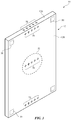
FIG. 1 is a perspective view of an illustrative electronic device with wireless communications circuitry in accordance with an embodiment. -
FIG. 2 is a schematic diagram of an illustrative electronic device with wireless communications circuitry in accordance with an embodiment. -
FIG. 3 is a perspective view of an illustrative electronic device showing illustrative locations at which antenna arrays for millimeter wave communications may be located in accordance with an embodiment. -
FIG. 4 is a diagram of an illustrative electronic device with wireless circuitry that allows radio-frequency signals to be distributed to phased antenna arrays in accordance with an embodiment. -
FIG. 5 is a diagram of an illustrative electronic device with wireless circuitry that includes intermediate frequency signal paths for distributing antenna signals within the device in accordance with an embodiment. -
FIG. 6 is a diagram showing how an intermediate frequency signal may be shared among multiple radio-frequency transceivers each of which is coupled to a respective antenna element in a phased antenna array in accordance with an embodiment. -
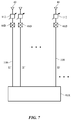
FIG. 7 is a diagram showing how intermediate frequency signals may be distributed individually to each of the antennas in an antenna array over parallel intermediate frequency signal paths in accordance with an embodiment. -
FIG. 8 is a diagram showing how antenna signals may be distributed using a ring-shaped signal distribution topology in accordance with an embodiment. -
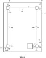
FIG. 9 is a perspective view of an illustrative integrated phased antenna array in accordance with an embodiment. -
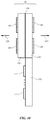
FIG. 10 is a side view of the illustrative integrated phased antenna array ofFIG. 9 in accordance with an embodiment. -
FIG. 11 is a side view of another illustrative integrated phased antenna array in accordance with an embodiment. -
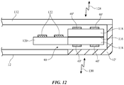
FIG. 12 is a cross-sectional side view of a corner portion of an illustrative electronic device in which a phased antenna array has been mounted in accordance with an embodiment. -
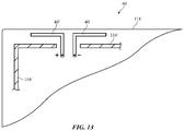
FIG. 13 is a diagram of a portion of a phased antenna array having a dipole antenna in accordance with an embodiment. - An electronic device such as
electronic device 10 ofFIG. 1 may contain wireless circuitry. The wireless circuitry may include one or more antennas. The antennas may include phased antenna arrays that are used for handling millimeter wave communications. Millimeter wave communications, which are sometimes referred to as extremely high frequency (EHF) communications, involve signals at 60 GHz or other frequencies between about 10 GHz and 400 GHz. If desired,device 10 may also contain wireless communications circuitry for handling satellite navigation system signals, cellular telephone signals, local wireless area network signals, near-field communications, light-based wireless communications, or other wireless communications. -
Electronic device 10 may be a computing device such as a laptop computer, a computer monitor containing an embedded computer, a tablet computer, a cellular telephone, a media player, or other handheld or portable electronic device, a smaller device such as a wrist-watch device, a pendant device, a headphone or earpiece device, a device embedded in eyeglasses or other equipment worn on a user's head, or other wearable or miniature device, a television, a computer display that does not contain an embedded computer, a gaming device, a navigation device, an embedded system such as a system in which electronic equipment with a display is mounted in a kiosk or automobile, equipment that implements the functionality of two or more of these devices, or other electronic equipment. In the illustrative configuration ofFIG. 1 ,device 10 is a portable device such as a cellular telephone, media player, tablet computer, or other portable computing device. Other configurations may be used fordevice 10 if desired. The example ofFIG. 1 is merely illustrative. - As shown in
FIG. 1 ,device 10 may include a display such asdisplay 14.Display 14 may be mounted in a housing such ashousing 12.Housing 12, which may sometimes be referred to as an enclosure or case, may be formed of plastic, glass, ceramics, fiber composites, metal (e.g., stainless steel, aluminum, etc.), other suitable materials, or a combination of any two or more of these materials.Housing 12 may be formed using a unibody configuration in which some or all ofhousing 12 is machined or molded as a single structure or may be formed using multiple structures (e.g., an internal frame structure, one or more structures that form exterior housing surfaces, etc.). -
Display 14 may be a touch screen display that incorporates a layer of conductive capacitive touch sensor electrodes or other touch sensor components (e.g., resistive touch sensor components, acoustic touch sensor components, force-based touch sensor components, light-based touch sensor components, etc.) or may be a display that is not touch-sensitive. Capacitive touch screen electrodes may be formed from an array of indium tin oxide pads or other transparent conductive structures. -
Display 14 may include an array of display pixels formed from liquid crystal display (LCD) components, an array of electrophoretic display pixels, an array of plasma display pixels, an array of organic light-emitting diode display pixels, an array of electrowetting display pixels, or display pixels based on other display technologies. -
Display 14 may be protected using a display cover layer such as a layer of transparent glass, clear plastic, sapphire, or other transparent dielectric. Openings may be formed in the display cover layer. For example, an opening may be formed in the display cover layer to accommodate a button such asbutton 16. An opening may also be formed in the display cover layer to accommodate ports such as a speaker port. Openings may be formed inhousing 12 to form communications ports (e.g., an audio jack port, a digital data port, etc.). Openings inhousing 12 may also be formed for audio components such as a speaker and/or a microphone. - Antennas may be mounted in
housing 12. To avoid disrupting communications when an external object such as a human hand or other body part of a user blocks one or more antennas, antennas may be mounted at multiple locations inhousing 12. Sensor data such as proximity sensor data, real-time antenna impedance measurements, signal quality measurements such as received signal strength information, and other data may be used in determining when an antenna (or set of antennas) is being adversely affected due to the orientation ofhousing 12, blockage by a user's hand or other external object, or other environmental factors.Device 10 can then switch an antenna (or set of antennas) into use in place of the antennas that are being adversely affected. - Antennas may be mounted along the peripheral edges of
housing 12, on the rear ofhousing 12, under the display cover glass or other dielectric display cover layer that is used in covering and protectingdisplay 14 on the front ofdevice 10, under a dielectric window on a rear face ofhousing 12 or the edge ofhousing 12, or elsewhere indevice 10. - A schematic diagram showing illustrative components that may be used in
device 10 is shown inFIG. 2 . As shown inFIG. 2 ,device 10 may include control circuitry such as storage andprocessing circuitry 30. Storage andprocessing circuitry 30 may include storage such as hard disk drive storage, nonvolatile memory (e.g., flash memory or other electrically-programmable-read-only memory configured to form a solid state drive), volatile memory (e.g., static or dynamic random-access-memory), etc. Processing circuitry in storage andprocessing circuitry 30 may be used to control the operation ofdevice 10. This processing circuitry may be based on one or more microprocessors, microcontrollers, digital signal processors, baseband processor integrated circuits, application specific integrated circuits, etc. - Storage and
processing circuitry 30 may be used to run software ondevice 10, such as internet browsing applications, voice-over-internet-protocol (VOIP) telephone call applications, email applications, media playback applications, operating system functions, etc. To support interactions with external equipment, storage andprocessing circuitry 30 may be used in implementing communications protocols. Communications protocols that may be implemented using storage andprocessing circuitry 30 include internet protocols, wireless local area network protocols (e.g., IEEE 802.11 protocols -- sometimes referred to as WiFi®), protocols for other short-range wireless communications links such as the Bluetooth® protocol, cellular telephone protocols, MIMO protocols, antenna diversity protocols, satellite navigation system protocols, etc. -
Device 10 may include input-output circuitry 44. Input-output circuitry 44 may include input-output devices 32. Input-output devices 32 may be used to allow data to be supplied todevice 10 and to allow data to be provided fromdevice 10 to external devices. Input-output devices 32 may include user interface devices, data port devices, and other input-output components. For example, input-output devices may include touch screens, displays without touch sensor capabilities, buttons, joysticks, scrolling wheels, touch pads, key pads, keyboards, microphones, cameras, speakers, status indicators, light sources, audio jacks and other audio port components, digital data port devices, light sensors, accelerometers or other components that can detect motion and device orientation relative to the Earth, capacitance sensors, proximity sensors (e.g., a capacitive proximity sensor and/or an infrared proximity sensor), magnetic sensors, a connector port sensor or other sensor that determines whetherdevice 10 is mounted in a dock, and other sensors and input-output components. - Input-
output circuitry 44 may includewireless communications circuitry 34 for communicating wirelessly with external equipment.Wireless communications circuitry 34 may include radio-frequency (RF) transceiver circuitry formed from one or more integrated circuits, power amplifier circuitry, low-noise input amplifiers, passive RF components, one ormore antennas 40, transmission lines, and other circuitry for handling RF wireless signals. Wireless signals can also be sent using light (e.g., using infrared communications). -
Wireless communications circuitry 34 may include radio-frequency transceiver circuitry 90 for handling various radio-frequency communications bands. For example,circuitry 34 may includetransceiver circuitry -
Transceiver circuitry 36 may be wireless local area network transceiver circuitry that may handle 2.4 GHz and 5 GHz bands for WiFi® (IEEE 802.11) communications and that may handle the 2.4 GHz Bluetooth® communications band. -
Circuitry 34 may use cellulartelephone transceiver circuitry 38 for handling wireless communications in frequency ranges such as a low communications band from 700 to 960 MHz, a midband from 1710 to 2170 MHz, and a high band from 2300 to 2700 MHz or other communications bands between 700 MHz and 2700 MHz or other suitable frequencies (as examples).Circuitry 38 may handle voice data and non-voice data. - Millimeter
wave transceiver circuitry 46 may support communications at extremely high frequencies (e.g., millimeter wave frequencies from 10GHz to 400 GHz or other millimeter wave frequencies). -
Wireless communications circuitry 34 may include satellite navigation system circuitry such as Global Positioning System (GPS)receiver circuitry 42 for receiving GPS signals at 1575 MHz or for handling other satellite positioning data (e.g., GLONASS signals at 1609 MHz). Satellite navigation system signals forreceiver 42 are received from a constellation of satellites orbiting the earth. - In satellite navigation system links, cellular telephone links, and other long-range links, wireless signals are typically used to convey data over thousands of feet or miles. In WiFi® and Bluetooth® links and other short-range wireless links, wireless signals are typically used to convey data over tens or hundreds of feet. Extremely high frequency (EHF)
wireless transceiver circuitry 46 may convey signals over these over these short distances that travel between transmitter and receiver over a line-of-sight path. To enhance signal reception for millimeter wave communications, phased antenna arrays and beam steering techniques may be used. Antenna diversity schemes may also be used to ensure that the antennas that have become blocked or that are otherwise degraded due to the operating environment ofdevice 10 can be switched out of use and higher-performing antennas used in their place. -
Wireless communications circuitry 34 can include circuitry for other short-range and long-range wireless links if desired. For example,wireless communications circuitry 34 may include circuitry for receiving television and radio signals, paging system transceivers, near field communications (NFC) circuitry, etc. -
Antennas 40 inwireless communications circuitry 34 may be formed using any suitable antenna types. For example,antennas 40 may include antennas with resonating elements that are formed from loop antenna structures, patch antenna structures, inverted-F antenna structures, slot antenna structures, planar inverted-F antenna structures, helical antenna structures, hybrids of these designs, etc. If desired, one or more ofantennas 40 may be cavity-backed antennas. Different types of antennas may be used for different bands and combinations of bands. For example, one type of antenna may be used in forming a local wireless link antenna and another type of antenna may be used in forming a remote wireless link antenna. Dedicated antennas may be used for receiving satellite navigation system signals or, if desired,antennas 40 can be configured to receive both satellite navigation system signals and signals for other communications bands (e.g., wireless local area network signals and/or cellular telephone signals).Antennas 40 can include phased antenna arrays for handling millimeter wave communications. - Transmission line paths may be used to route antenna signals within
device 10. For example, transmission line paths may be used to coupleantenna structures 40 totransceiver circuitry 90. Transmission lines indevice 10 may include coaxial cable paths, microstrip transmission lines, stripline transmission lines, edge-coupled microstrip transmission lines, edge-coupled stripline transmission lines, transmission lines formed from combinations of transmission lines of these types, etc. Filter circuitry, switching circuitry, impedance matching circuitry, and other circuitry may be interposed within the transmission lines, if desired. -
Device 10 may containmultiple antennas 40. The antennas may be used together or one of the antennas may be switched into use while other antenna(s) are switched out of use. If desired,control circuitry 30 may be used to select an optimum antenna to use indevice 10 in real time and/or to select an optimum setting for adjustable wireless circuitry associated with one or more ofantennas 40. Antenna adjustments may be made to tune antennas to perform in desired frequency ranges, to perform beam steering with a phased antenna array, and to otherwise optimize antenna performance. Sensors may be incorporated intoantennas 40 to gather sensor data in real time that is used in adjustingantennas 40. - In some configurations,
antennas 40 may include antenna arrays (e.g., phased antenna arrays to implement beam steering functions). For example, the antennas that are used in handling millimeter wave signals for extremely high frequencywireless transceiver circuits 46 may be implemented as phased antenna arrays. The radiating elements in a phased antenna array for supporting millimeter wave communications may be patch antennas, dipole antennas, or other suitable antenna elements. Transceiver circuitry can be integrated with the phased antenna arrays to form integrated phased antenna array and transceiver circuit modules. - In devices such as handheld devices, the presence of an external object such as the hand of a user or a table or other surface on which a device is resting has a potential to block wireless signals such as millimeter wave signals. Accordingly, it may be desirable to incorporate multiple phased antenna arrays into
device 10, each of which is placed in a different location withindevice 10. With this type of arrangement, an unblocked phased antenna array may be switched into use and, once switched into use, the phased antenna array may use beam steering to optimize wireless performance. Configurations in which antennas from one or more different locations indevice 10 are operated together may also be used (e.g., to form a phased antenna array, etc.). -
FIG. 3 is a perspective view of electronic device showingillustrative locations 50 in which antennas 40 (e.g., single antennas and/or phased antenna arrays for use withwireless circuitry 34 such as millimeter wave wireless transceiver circuitry 46) may be mounted indevice 10. As shown inFIG. 3 ,antennas 40 may be mounted at the corners ofdevice 10, along the edges ofhousing 12 such asedge 12E, on the upper and lower portions ofrear housing portion 12R, in the center of rear housing 12 (e.g., under a dielectric window structure such as plastic logo 52), etc. In configurations in whichhousing 12 is formed from a dielectric,antennas 40 may transmit and receive antenna signals through the dielectric. In configurations in whichhousing 12 is formed from a conductive material such as metal, slots or other openings may be formed in the metal that are filled with plastic or other dielectric.Antennas 40 may be mounted in alignment with the dielectric (i.e., the dielectric inhousing 12 may serve as one or more antenna windows for antennas 40). - In devices with multiple phased antenna arrays, signal paths such as
paths 100 ofFIG. 4 (e.g., transmission lines) may be used to distribute millimeter wave signals toantennas 40. In the example ofFIG. 4 ,wireless transceiver 46 may be used to transmit and receive millimeter wave signals (i.e., radio-frequency signals at RF frequencies such as 60 GHz).Paths 100 may be used to distribute these radio-frequency signals to antenna arrays such as phasedantenna arrays phase adjustment circuitry 106 may be used to adjust the signals associated with eachantenna 40 inarray 40A and to adjust the signals associated with eachantenna 40 inarray 40B. As shown by the illustrative configuration ofarray 40B inFIG. 4 ,paths 100 may include multipleparallel paths 100 each of which is connected between arespective transceiver 46 and arespective antenna 40 in phasedantenna array 40B. Gain andphase adjustment circuits 106 may be used to individually adjust the signals associated with eachantenna 40 inarray 40B (e.g., to perform beam steering). If desired, RF signals (e.g., 60 GHz signals) may be distributed to coupler (splitter 102) in a phased antenna array such as phasedantenna array 40A via a single one ofpaths 100 and distributed bycoupler 102 torespective circuits 106 andantennas 40 in phasedantenna array 40A. Received signals may be supplied topath 100 viacircuits 106 andcoupler 102. - At high RF frequencies (e.g. at 60 GHz or other millimeter wave frequencies), signals can be attenuated on the paths between
transceiver circuitry 46 andantennas 40 more strongly than at lower RF frequencies. To help minimize attenuation, it may be desirable to distribute antenna signals withindevice 10 at intermediate frequencies (IF). The intermediate frequency signals IF indevice 10 may, as an example, be signals at 5-15 GHz, whereas the radio-frequency (RF) signals indevice 10 may have higher frequencies such as 60 GHz or other millimeter wave frequencies. Internal distribution path attenuation will generally be lower at intermediate frequencies IF than at radio frequencies RF, which may allow the antenna arrays indevice 10 to be located farther apart without introducing excessive signal path attenuation. - An illustrative configuration for
device 10 in which signals are distributed at intermediate frequencies is shown inFIG. 5 . As shown inFIG. 5 , each antenna 40 (e.g., each phased antenna array) indevice 10 may be provided withcircuitry 46B.Circuitry 46B may include radio-frequency transceiver circuitry (e.g., 60 GHz transceiver circuitry) with upconversion and downconversion capabilities. Each block ofcircuitry 46B ofFIG. 5 may, for example, include an upconverter that upconverts IF signals frombaseband processor 46A on an associated one ofIF paths 108 to RF signals (e.g., signals at 60 GHz). These RF signals may then be provided to antennas 40 (e.g., phased antenna arrays) via one ofRF signal paths 100 and transmitted over the air to a remote millimeter wave receiver. RF signals that are received by each phased antenna array may be supplied tocircuitry 46B via arespective path 100. A downconverter incircuitry 46B may then downconvert the received RF signal to an IF signal. An associated one ofIF signal paths 108 may be used to convey the IF signal tobaseband processor 46A. - An illustrative circuit diagram for a phased antenna array for
device 10 is shown inFIG. 6 . In the example ofFIG. 6 , the phased antenna array has been formed from an array of antennas (antenna elements) 40. Intermediate frequency signals IF may be conveyed to the phased antenna array over intermediate frequency path IF. Coupler (splitter) 110 may provide the IF signals torespective transceiver circuits 46B. An upconverter in eachtransceiver circuit 46B may upconvert the IF signal to a corresponding RF signal that is provided to arespective antenna element 40 to transmit wirelessly. Eachantenna element 40 may be associated with a respectiveadjustable circuit 112. Eachadjustable circuit 112 may include an adjustable gain output amplifier and an adjustable phase shifter for controlling the RF signals supplied fromcircuit 46B toantenna 40. - Another illustrative arrangement for distributing IF signals to a phased antenna array is shown in
FIG. 7 . The phased antenna array ofFIG. 7 includes an array ofantennas 40 each of which is coupled to an associated adjustable circuit 112 (e.g., an adjustable gain amplifier and adjustable phase shifter). Intermediate frequency signals IF may be distributed totransceiver circuits 46B using respective parallel intermediatefrequency signal paths 108. - In the example of
FIG. 8 , wireless signals (e.g., IF signals) are being distributed using a series ofIF signal paths 108 that are coupled in a ring. Each node of the ring has one ofcircuits 114.Circuits 114 may each include RF transceiver circuitry for transmitting and receiving signals via an associated one of phasedantenna arrays 40. Eachcircuit 114 may include a splitter that splits an incoming IF signal into an outgoing IF signal and a tapped IF signal. An upconverter in eachcircuit 114 may be used to locally upconvert the tapped IF signal in thatcircuit 114 so that the signal can be transmitted via theantenna array 40 that is coupled to that circuit. Incoming RF signals that have been received by eachantenna array 40 may be received by the RF transceiver circuitry in an associatedcircuit 114 and downconverted to corresponding IF signals by a downconverter in thatcircuit 114.Signals paths 108 may be coupled betweenrespective circuits 114 to form a ring-shaped distribution path for IF signals indevice 10. If desired, RF signals (e.g., 60 GHz signals) may be distributed using a ring-shaped arrangement of this type. The illustrative configuration ofFIG. 8 in which the ring formed frompaths 108 is used to distribute IF signals is merely illustrative. -
FIG. 9 is a perspective view of an illustrative phased antenna array of the type that may be used for handling millimeter wave signals (e.g., 60 GHz signals) indevice 10. In the configuration ofFIG. 9 , phasedantenna array 40 includes multiple antenna elements 40' (e.g., patch antenna elements). There may be, for example, a square array of four elements 40' on the front face ofantenna array 40 and a square array of four elements 40' on the opposing rear face ofantenna array 40. The use of a phased array of elements such as elements 40' allows the radio-frequency signals ofantenna array 40 to be steered using beam steering techniques. Elements 40' may be formed from metal traces on dielectric substrate layers 118 (e.g., rigid printed circuit board material, ceramic, plastic, glass, or other dielectric).Metal ground layer 116 may be interposed betweenlayers 118 and may serve as a signal reflector. Electrical components 122 (e.g., transceiver circuitry such ascircuitry 46B,circuitry 114, etc.) may be mounted onsubstrate 120.Substrate 120 may be integrated with the other components ofarray 40. Forexample substrate 120 may be an extended portion of one or both oflayers 118 or may be attached tolayers 118 to form an integrated transceiver and antenna array module. - A cross-sectional side view of phased
antenna array 40 ofFIG. 9 is shown inFIG. 10 . As shown inFIG. 10 , antenna elements 40' may be located on opposing sides ofground layer 116. The thickness oflayers 118 may be selected to space elements 40' on one side oflayers 118 by a half of a wavelength from the elements 40' on the other side oflayers 118. During operation, only the elements 40' on a first side ofarray 40 may be used (e.g., the left side oflayers 118 in the orientation ofFIG. 10 ), so that antenna signals may be transmitted indirection 126, only elements 40' on the opposing side ofarray 40 may be used, so that antenna signals may be transmitted indirection 124, or the elements 40' on both sides oflayers 118 may be used (e.g., to simultaneously handle antenna signals on both sides of layers 118). - If desired, components such as
components 122 may be mounted within a cavity formed between two sandwichedsubstrates 118, as shown inFIG. 11 . With this type of arrangement, layers 118 may be attached to each other usingdielectric layers 118', thereby forming a system-in-package structure that incorporates both antenna circuitry 122 (e.g.,transceiver circuitry 46B,circuits 114, etc.) and antenna elements 40'. Two ground (reflector) layers 116A and 116B may be provided in this type of configuration to help shieldcomponents 122 from radio-frequency antenna signals that are being handled by antenna elements 40' on the opposing outer surfaces ofarray 40. -
FIG. 12 is a cross-sectional side view of a portion ofdevice 10 near one of the corners ofhousing 12 showing how a phased antenna array such asarray 40 ofFIGS. 9 and10 orarray 40 ofFIG. 11 (e.g., phased antenna array and transceiver modules) may be mounted withindevice 10. As shown in the illustrative configuration ofFIG. 12 ,antenna array 40 may be mounted so that elements 40' on the top side ofarray 40 transmit and receiveantenna signals 128 through display cover layer 132 (i.e., a glass layer, plastic layer, or other protective dielectric layer for display 14). Elements 40' on the lower side ofarray 40 may transmit and receiveantenna signals 130 through dielectric layer 12'. Layer 12' may be a housing portion such as a dielectric antenna window formed within an opening in a metal housing 12 (as an example). - As shown in the top view of
antenna array 40 in the illustrative arrangement ofFIG. 13 ,antenna array 40 may include a ring-shaped ground reflector such as ground reflector 116'. Dipole antenna elements 40' may protrude through openings in ground ring 116'. In a configuration in whichantenna array 40 is mounted in a corner ofdevice 10, two of the edges ofantenna array 40 may be adjacent to tworespective edges 12E ofhousing 12. Antenna windows may be formed on these edges (e.g., plastic windows formed in openings in a metal housing).Antenna array 40 may have dipole elements 40' that run along each of these two edges. If desired patch antenna elements (see, e.g., elements 40' ofFIGS. 9 ,10 , and11 ) may be included on an antenna array in addition to dipole elements of the type shown inFIG. 13 . - In accordance with an embodiment, an electronic device is provided that includes a housing, a baseband processor, a plurality of phased antenna arrays, a plurality of transceiver circuits each of which is associated with a respective one of the phased antenna arrays and each of which includes a radio-frequency transceiver, and a plurality of intermediate frequency signal paths each of which is coupled between the baseband processor and a respective one of the transceiver circuits, each transceiver circuit includes an upconverter that receives intermediate frequency signals from the baseband processor over a respective one of the plurality of intermediate frequency signal paths and that upconverts those intermediate frequency signals to radio-frequency signals that are provided to a respective one of the phased antenna arrays and each transceiver circuit includes a downconverter that receives radio-frequency antenna signals from that respective one of the phased antenna arrays and downconverts those received radio-frequency antenna signals to intermediate frequency signals that are conveyed to the baseband processor over the intermediate frequency signal path that is coupled to that respective transceiver circuit.
- In accordance with another embodiment, each phased antenna array includes multiple antenna elements on a dielectric.
- In accordance with another embodiment, each phased antenna array includes a ground reflector.
- In accordance with another embodiment, the antenna elements includess patch antenna elements.
- In accordance with another embodiment, the dielectric includess a dielectric layer that is interposed between the patch antenna elements and the ground reflector.
- In accordance with another embodiment, each phased antenna array includes at least one dielectric layer, and at least one electrical component on the dielectric layer that forms part of the transceiver circuit that is associated with that phased antenna array.
- In accordance with another embodiment, each phased antenna array has a metal ground layer, a first array of antenna elements, a first dielectric layer interposed between the metal ground layer and the first array of antenna elements, a second array of antenna elements, and a second dielectric layer interposed between the metal ground layer and the second array of antenna elements.
- In accordance with another embodiment, the first and second arrays of antenna elements include patch antenna elements.
- In accordance with another embodiment, the electronic device includes a transceiver circuit component on the first dielectric layer.
- In accordance with another embodiment, the housing has four corners and each of the phased antenna arrays is located at one of the four corners.
- In accordance with another embodiment, each phased antenna array has an array of antenna elements and at least one of the arrays of antenna elements runs parallel to an edge of the housing.
- In accordance with another embodiment, the electronic device includes a display mounted in the housing that has a display cover layer, where at least one of the phased antenna arrays emits antenna signals through the display cover layer.
- In accordance with another embodiment, the electronic device includes a dielectric logo on a rear face of the housing, one of the phased antenna arrays is mounted under the dielectric logo.
- In accordance with another embodiment, the phased antenna arrays include millimeter wave phased antenna arrays.
- In accordance with another embodiment, the housing includes a portable electronic device housing for an electronic device selected from the group consisting of a cellular telephone, a tablet computer, and a laptop computer.
- In accordance with an embodiment, a millimeter wave phased antenna array that transmits and receives millimeter wave signals in a portable electronic device is provided that includes a ground layer, and a first array of antenna elements, a first dielectric layer interposed between the metal ground layer and the first array of antenna elements, a second array of antenna elements, and a second dielectric layer interposed between the metal ground layer and the second array of antenna elements.
- In accordance with another embodiment, the first and second arrays of antenna elements include first and second arrays of patch antenna elements.
- In accordance with another embodiment, the millimeter wave phased antenna array includes transceiver circuitry mounted on the first dielectric layer.
- In accordance with an embodiment, an electronic device is provided that includes a housing having corners with dielectric portions, a display having a dielectric layer that is mounted in the housing, and a plurality of millimeter wave phased antenna arrays mounted in the housing at the corners so that antenna signals from the millimeter wave phased antenna arrays pass through the dielectric layer and through the dielectric portions.
- In accordance with another embodiment, each millimeter wave phased antenna array includes a first array of antenna elements, a first dielectric layer interposed between the metal ground layer and the first array of antenna elements, a second array of antenna elements, and a second dielectric layer interposed between the metal ground layer and the second array of antenna elements.
- The foregoing is merely illustrative and various modifications can be made by those skilled in the art without departing from the scope and spirit of the described embodiments. The foregoing embodiments may be implemented individually or in any combination.
-
- 1. An electronic device, comprising:
- a housing;
- a baseband processor;
- a plurality of phased antenna arrays;
- a plurality of transceiver circuits each of which is associated with a respective one of the phased antenna arrays and each of which includes a radio-frequency transceiver; and
- a plurality of intermediate frequency signal paths each of which is coupled between the baseband processor and a respective one of the transceiver circuits, wherein each transceiver circuit includes an upconverter that receives intermediate frequency signals from the baseband processor over a respective one of the plurality of intermediate frequency signal paths and that upconverts those intermediate frequency signals to radio-frequency signals that are provided to a respective one of the phased antenna arrays and wherein each transceiver circuit includes a downconverter that receives radio-frequency antenna signals from that respective one of the phased antenna arrays and downconverts those received radio-frequency antenna signals to intermediate frequency signals that are conveyed to the baseband processor over the intermediate frequency signal path that is coupled to that respective transceiver circuit.
- 2. The electronic device defined in embodiment 1 wherein each phased antenna array includes multiple antenna elements on a dielectric.
- 3. The electronic device defined in embodiment 2 wherein each phased antenna array includes a ground reflector.
- 4. The electronic device defined in embodiment 3 wherein the antenna elements comprises patch antenna elements.
- 5. The electronic device defined in embodiment 4 wherein the
dielectric
comprises a dielectric layer that is interposed between the patch antenna elements and the ground reflector. - 6. The electronic device defined in embodiment 1 wherein each phased antenna array comprises:
- at least one dielectric layer; and
- at least one electrical component on the dielectric layer that forms part of the transceiver circuit that is associated with that phased antenna array.
- 7. The electronic device defined in embodiment 1 wherein each phased antenna array has a metal ground layer, a first array of antenna elements, a first dielectric layer interposed between the metal ground layer and the first array of antenna elements, a second array of antenna elements, and a second dielectric layer interposed between the metal ground layer and the second array of antenna elements.
- 8. The electronic device defined in embodiment 7 wherein the first and second arrays of antenna elements comprise patch antenna elements.
- 9. The electronic device defined in embodiment 8 further comprising a transceiver circuit component on the first dielectric layer.
- 10. The electronic device defined in embodiment 1 wherein the housing has four corners and wherein each of the phased antenna arrays is located at one of the four corners.
- 11. The electronic device defined in
embodiment 10 wherein each phased antenna array has an array of antenna elements and wherein at least one of the arrays of antenna elements runs parallel to an edge of the housing. - 12. The electronic device defined in embodiment 1 further comprising a display mounted in the housing that has a display cover layer, wherein at least one of the phased antenna arrays emits antenna signals through the display cover layer.
- 13. The electronic device defined in embodiment 1 further comprising a dielectric logo on a rear face of the housing, wherein one of the phased antenna arrays is mounted under the dielectric logo.
- 14. The electronic device defined in embodiment 1 wherein the phased antenna arrays comprise millimeter wave phased antenna arrays.
- 15. The electronic device defined in
embodiment 14 wherein the housing comprises a portable electronic device housing for an electronic device selected from the group consisting of: a cellular telephone, a tablet computer, and a laptop computer. - 16. A millimeter wave phased antenna array that transmits and receives millimeter wave signals in a portable electronic device, comprising: a ground layer; and
a first array of antenna elements, a first dielectric layer interposed between the metal ground layer and the first array of antenna elements, a second array of antenna elements, and a second dielectric layer interposed between the metal ground layer and the second array of antenna elements. - 17. The millimeter wave phased antenna array defined in
embodiment 16 wherein the first and second arrays of antenna elements comprise first and second arrays of patch antenna elements. - 18. The millimeter wave phased antenna array defined in embodiment 17 further comprising transceiver circuitry mounted on the first dielectric layer.
- 19. An electronic device, comprising:
a housing having corners with dielectric portions;
a display having a dielectric layer that is mounted in the housing; and a plurality of millimeter wave phased antenna arrays mounted in the housing at the corners so that antenna signals from the millimeter wave phased antenna arrays pass through the dielectric layer and through the dielectric portions. - 20. The electronic device defined in embodiment 19 wherein each millimeter wave phased antenna array comprises a first array of antenna elements, a first dielectric layer interposed between the metal ground layer and the first array of antenna elements, a second array of antenna elements, and a second dielectric layer interposed between the metal ground layer and the second array of antenna elements.
Claims (8)
- Apparatus, comprising:a first dielectric layer having a first portion and a second portion that is different from the first portion;a second dielectric layer formed over the first portion of the first dielectric layer;
a millimeter wave phased antenna array that includes an array of antenna elements formed on the second dielectric layer; andtransceiver circuitry, wherein the transceiver circuitry is mounted to the second portion of the first dielectric layer. - The apparatus defined in claim 1, wherein the second dielectric layer has a lateral area, the second dielectric layer covers the first portion of the first dielectric layer, and the second portion of the first dielectric layer extends beyond the lateral area of the second dielectric layer.
- The apparatus defined in claim 1, further comprising:
a conductive ground layer interposed between the first and second dielectric layers. - The apparatus defined in claim 1, further comprising:
an additional millimeter wave phased antenna array that includes an additional array of antenna elements formed on the first dielectric layer. - The apparatus defined in claim 4, wherein the first dielectric layer is interposed between the second dielectric layer and the additional array of antenna elements.
- The apparatus defined in claim 5, further comprising:
a conductive ground layer between the millimeter wave phased antenna array and the additional millimeter wave phased antenna array, wherein the millimeter wave phased antenna array is configured to transmit and receive antenna signals through a display cover glass and the additional millimeter wave phased antenna array is configured to transmit and receive antenna signals through a dielectric window in a housing. - The apparatus defined in claim 1, wherein the array of antenna elements comprises an array of patch antenna elements.
- The apparatus defined in claim 1, wherein the apparatus comprises an electronic device selected from the group consisting of: a cellular telephone, a tablet computer, and a laptop computer.
Applications Claiming Priority (4)
| Application Number | Priority Date | Filing Date | Title |
|---|---|---|---|
| US201562149430P | 2015-04-17 | 2015-04-17 | |
| US15/097,868 US9667290B2 (en) | 2015-04-17 | 2016-04-13 | Electronic device with millimeter wave antennas |
| EP16718163.5A EP3284136B1 (en) | 2015-04-17 | 2016-04-14 | Electronic device with millimeter wave antennas |
| PCT/US2016/027487 WO2016168432A1 (en) | 2015-04-17 | 2016-04-14 | Electronic device with millimeter wave antennas |
Related Parent Applications (2)
| Application Number | Title | Priority Date | Filing Date |
|---|---|---|---|
| EP16718163.5A Division EP3284136B1 (en) | 2015-04-17 | 2016-04-14 | Electronic device with millimeter wave antennas |
| EP16718163.5A Division-Into EP3284136B1 (en) | 2015-04-17 | 2016-04-14 | Electronic device with millimeter wave antennas |
Publications (1)
| Publication Number | Publication Date |
|---|---|
| EP3751662A1 true EP3751662A1 (en) | 2020-12-16 |
Family
ID=55806867
Family Applications (2)
| Application Number | Title | Priority Date | Filing Date |
|---|---|---|---|
| EP16718163.5A Active EP3284136B1 (en) | 2015-04-17 | 2016-04-14 | Electronic device with millimeter wave antennas |
| EP20189669.3A Withdrawn EP3751662A1 (en) | 2015-04-17 | 2016-04-14 | Electronic device with millimeter wave antennas |
Family Applications Before (1)
| Application Number | Title | Priority Date | Filing Date |
|---|---|---|---|
| EP16718163.5A Active EP3284136B1 (en) | 2015-04-17 | 2016-04-14 | Electronic device with millimeter wave antennas |
Country Status (4)
| Country | Link |
|---|---|
| US (6) | US9667290B2 (en) |
| EP (2) | EP3284136B1 (en) |
| CN (4) | CN112366460B (en) |
| WO (1) | WO2016168432A1 (en) |
Families Citing this family (153)
| Publication number | Priority date | Publication date | Assignee | Title |
|---|---|---|---|---|
| US9860760B2 (en) * | 2014-11-26 | 2018-01-02 | Avago Technologies General Ip (Singapore) Pte. Ltd. | Scalable radio frequency communication system |
| US9900196B2 (en) | 2014-11-26 | 2018-02-20 | Avago Technologies General Ip (Singapore) Pte. Ltd. | Switching diversity in scalable radio frequency communication system |
| US9667290B2 (en) * | 2015-04-17 | 2017-05-30 | Apple Inc. | Electronic device with millimeter wave antennas |
| US10361476B2 (en) * | 2015-05-26 | 2019-07-23 | Qualcomm Incorporated | Antenna structures for wireless communications |
| US10405316B2 (en) * | 2015-10-19 | 2019-09-03 | Keyssa Systems, Inc. | Contactless connector location systems and methods |
| US10887439B2 (en) * | 2015-12-22 | 2021-01-05 | Intel Corporation | Microelectronic devices designed with integrated antennas on a substrate |
| EP3400630B1 (en) * | 2016-01-07 | 2022-09-28 | Georgia Tech Research Corporation | Reconfigurable antennas and methods of operating the same |
| WO2017122905A1 (en) * | 2016-01-11 | 2017-07-20 | Samsung Electronics Co., Ltd. | Wireless communication device with leaky-wave phased array antenna |
| US10547339B2 (en) | 2016-01-29 | 2020-01-28 | Apple Inc. | Electronic devices having millimeter wave wireless data transfer capabilities |
| WO2018039766A1 (en) | 2016-08-29 | 2018-03-08 | Beam Semiconductor Ltd. | Antenna modules and systems, and applications and methods of manufacturing thereof |
| US11678445B2 (en) | 2017-01-25 | 2023-06-13 | Apple Inc. | Spatial composites |
| KR20210146432A (en) | 2017-03-29 | 2021-12-03 | 애플 인크. | Device having integrated interface system |
| WO2018186226A1 (en) * | 2017-04-07 | 2018-10-11 | 株式会社村田製作所 | Antenna module and communication device |
| CN106842672B (en) * | 2017-04-19 | 2019-07-26 | 京东方科技集团股份有限公司 | A kind of display device |
| US20180309189A1 (en) * | 2017-04-21 | 2018-10-25 | Huanhuan GU | Broadband mimo antenna system for electronic device |
| US10305171B1 (en) * | 2017-04-24 | 2019-05-28 | Blue Digs LLC | Electronic devices with antenna arrays |
| US10256872B2 (en) | 2017-05-02 | 2019-04-09 | Apple Inc. | Methods for performing antenna beam scanning |
| AU2017413139B2 (en) | 2017-05-12 | 2021-05-13 | Huawei Technologies Co., Ltd. | Communication device |
| US10944180B2 (en) * | 2017-07-10 | 2021-03-09 | Viasat, Inc. | Phased array antenna |
| US10658762B2 (en) | 2017-07-14 | 2020-05-19 | Apple Inc. | Multi-band millimeter wave antenna arrays |
| US10763566B2 (en) | 2017-07-20 | 2020-09-01 | Apple Inc. | Millimeter wave transmission line structures |
| KR101921182B1 (en) * | 2017-07-25 | 2018-11-22 | 엘지전자 주식회사 | Array antenna and mobile terminal |
| US10826193B2 (en) | 2017-07-28 | 2020-11-03 | Samsung Electro-Mechanics Co., Ltd. | Antenna module including a flexible substrate |
| WO2019029819A1 (en) * | 2017-08-11 | 2019-02-14 | Telefonaktiebolaget Lm Ericsson (Publ) | Integrated circuit with clock distribution |
| KR102413663B1 (en) * | 2017-09-04 | 2022-06-28 | 삼성전자주식회사 | An electronic device comprising an antenna |
| US10062970B1 (en) * | 2017-09-05 | 2018-08-28 | At&T Intellectual Property I, L.P. | Dual mode communications device and methods for use therewith |
| US10263332B2 (en) | 2017-09-18 | 2019-04-16 | Apple Inc. | Antenna arrays with etched substrates |
| US10553945B2 (en) | 2017-09-20 | 2020-02-04 | Apple Inc. | Antenna arrays having surface wave interference mitigation structures |
| US11121447B2 (en) * | 2017-09-27 | 2021-09-14 | Apple Inc. | Dielectric covers for antennas |
| KR102439813B1 (en) * | 2017-09-29 | 2022-09-02 | 엘지전자 주식회사 | mobile terminal |
| JP6941732B2 (en) | 2017-09-29 | 2021-09-29 | アップル インコーポレイテッドApple Inc. | Multipart device enclosure |
| US10455065B2 (en) | 2017-09-29 | 2019-10-22 | Lg Electronics Inc. | Mobile terminal |
| US11245175B2 (en) | 2017-09-30 | 2022-02-08 | Qualcomm Incorporated | Antenna module configurations |
| EP3679626A4 (en) * | 2017-10-11 | 2021-05-26 | Wispry, Inc. | User insensitive steerable antenna array devices, systems, and methods |
| US10775490B2 (en) | 2017-10-12 | 2020-09-15 | Infineon Technologies Ag | Radio frequency systems integrated with displays and methods of formation thereof |
| KR102402492B1 (en) * | 2017-11-01 | 2022-05-27 | 삼성전자주식회사 | An electronic device comprising an antenna |
| KR102005744B1 (en) * | 2017-11-24 | 2019-07-31 | (주)텔리언 | Head Mount Device having Millimeter Wave Position Sensor |
| KR102415591B1 (en) * | 2017-11-24 | 2022-07-04 | 삼성전자주식회사 | Electronic device for including antenna array |
| KR20190060283A (en) | 2017-11-24 | 2019-06-03 | 삼성전자주식회사 | An electronic device comprising an antenna |
| KR102424681B1 (en) * | 2017-11-27 | 2022-07-25 | 삼성전자주식회사 | Arrangement structure for 5g communication device and electronic device including the same |
| KR102387939B1 (en) * | 2017-11-28 | 2022-04-19 | 삼성전자주식회사 | An antenna and an electronic device comprising the antenna |
| KR102491506B1 (en) * | 2017-11-28 | 2023-01-25 | 삼성전자주식회사 | An electronic device comprising antenna |
| CN108155471A (en) * | 2017-11-30 | 2018-06-12 | 努比亚技术有限公司 | The antenna structure and its mobile terminal that a kind of becket shields comprehensively |
| US11228342B2 (en) * | 2017-12-04 | 2022-01-18 | John F. Sevic | High bandwidth scalable wireless near-field interface |
| WO2019113112A1 (en) * | 2017-12-04 | 2019-06-13 | Maja Systems, Inc. | High bandwidth scalable wireless near-field interface |
| CN108232470A (en) * | 2017-12-13 | 2018-06-29 | 瑞声科技(南京)有限公司 | A kind of antenna system and mobile terminal |
| CN108199153A (en) * | 2017-12-13 | 2018-06-22 | 瑞声科技(南京)有限公司 | Antenna system and mobile terminal |
| US11664581B2 (en) * | 2017-12-20 | 2023-05-30 | Huawei Technologies Co., Ltd. | Communication device and a method in a communication device |
| CN111801848A (en) * | 2018-01-05 | 2020-10-20 | 维斯普瑞公司 | Corner antenna array device, system and method |
| CN108259648B (en) * | 2018-01-12 | 2020-12-15 | 深圳天珑无线科技有限公司 | Mobile device |
| US11355840B2 (en) * | 2018-01-16 | 2022-06-07 | Metawave Corporation | Method and apparatus for a metastructure switched antenna in a wireless device |
| CN108232473B (en) * | 2018-01-19 | 2021-02-19 | Oppo广东移动通信有限公司 | Antenna assembly, electronic device and antenna switching method |
| KR102511737B1 (en) * | 2018-01-24 | 2023-03-20 | 삼성전자주식회사 | Antenna structure and electronic device comprising antenna structure |
| CN108448229A (en) * | 2018-01-25 | 2018-08-24 | 瑞声科技(南京)有限公司 | Antenna system and communicating terminal |
| US10727570B2 (en) * | 2018-01-30 | 2020-07-28 | Apple Inc. | Electronic devices having antennas that radiate through a display |
| US20190260110A1 (en) * | 2018-02-20 | 2019-08-22 | Intel Corporation | Antenna modules and communication devices |
| US10895634B2 (en) * | 2018-02-21 | 2021-01-19 | Apple Inc. | Electronic devices having millimeter wave ranging capabilities |
| US10355344B1 (en) | 2018-02-23 | 2019-07-16 | Apple Inc. | Electronic devices having antenna diversity capabilities |
| US10476170B2 (en) | 2018-02-27 | 2019-11-12 | Apple Inc. | Antenna arrays having conductive shielding buckets |
| US10826177B2 (en) * | 2018-02-27 | 2020-11-03 | Apple Inc. | Electronic devices having phased antenna arrays for performing proximity detection operations |
| KR102472237B1 (en) | 2018-03-09 | 2022-11-30 | 삼성전자주식회사 | Electronic device for including antenna |
| US10396470B1 (en) * | 2018-03-16 | 2019-08-27 | Peraso Technologies Inc. | Wireless system architecture with dependent superstrate for millimeter-wave phased-array antennas |
| US11380979B2 (en) | 2018-03-29 | 2022-07-05 | Intel Corporation | Antenna modules and communication devices |
| US10879585B2 (en) * | 2018-04-09 | 2020-12-29 | Lg Electronics Inc. | Mobile terminal |
| US11139588B2 (en) | 2018-04-11 | 2021-10-05 | Apple Inc. | Electronic device antenna arrays mounted against a dielectric layer |
| US11011827B2 (en) | 2018-05-11 | 2021-05-18 | Intel IP Corporation | Antenna boards and communication devices |
| CN108666738A (en) | 2018-05-17 | 2018-10-16 | 京东方科技集团股份有限公司 | A kind of liquid crystal antenna and preparation method thereof, driving method and communication equipment |
| CN111356979B (en) | 2018-05-25 | 2023-12-29 | 苹果公司 | Portable computer with dynamic display interface |
| US11509037B2 (en) | 2018-05-29 | 2022-11-22 | Intel Corporation | Integrated circuit packages, antenna modules, and communication devices |
| US10797394B2 (en) | 2018-06-05 | 2020-10-06 | Intel Corporation | Antenna modules and communication devices |
| US10608344B2 (en) * | 2018-06-07 | 2020-03-31 | Apple Inc. | Electronic device antenna arrays mounted against a dielectric layer |
| CN108832250B (en) * | 2018-06-22 | 2021-07-09 | 瑞声科技(南京)有限公司 | Antenna assembly and mobile terminal |
| US10727580B2 (en) | 2018-07-16 | 2020-07-28 | Apple Inc. | Millimeter wave antennas having isolated feeds |
| US11108155B2 (en) | 2018-07-16 | 2021-08-31 | Apple Inc. | Electronic devices having distributed millimeter wave antennas |
| KR102514547B1 (en) | 2018-07-16 | 2023-03-27 | 삼성전자주식회사 | Display assembly including antenna and electronic device with the same |
| KR20200014601A (en) * | 2018-08-01 | 2020-02-11 | 삼성전자주식회사 | Electronic device for including antenna array |
| CN208589528U (en) * | 2018-08-03 | 2019-03-08 | 瑞声科技(南京)有限公司 | Millimeter wave array antenna framework |
| US11175769B2 (en) | 2018-08-16 | 2021-11-16 | Apple Inc. | Electronic device with glass enclosure |
| KR20200024408A (en) * | 2018-08-28 | 2020-03-09 | 삼성전자주식회사 | Electronic device for including antenna array |
| US11258163B2 (en) | 2018-08-30 | 2022-02-22 | Apple Inc. | Housing and antenna architecture for mobile device |
| US11133572B2 (en) | 2018-08-30 | 2021-09-28 | Apple Inc. | Electronic device with segmented housing having molded splits |
| US10705570B2 (en) | 2018-08-30 | 2020-07-07 | Apple Inc. | Electronic device housing with integrated antenna |
| CN208820046U (en) * | 2018-08-30 | 2019-05-03 | 易力声科技(深圳)有限公司 | A kind of dipole antenna being placed in wireless headset shell |
| US11189909B2 (en) | 2018-08-30 | 2021-11-30 | Apple Inc. | Housing and antenna architecture for mobile device |
| KR102526543B1 (en) * | 2018-09-10 | 2023-04-28 | 삼성전자주식회사 | An electronic device comprising an antenna module |
| US10957985B2 (en) | 2018-09-28 | 2021-03-23 | Apple Inc. | Electronic devices having antenna module isolation structures |
| CN109193119B (en) * | 2018-09-28 | 2021-08-17 | 北京小米移动软件有限公司 | Terminal housings and terminals |
| KR102537495B1 (en) | 2018-10-02 | 2023-05-26 | 삼성전자주식회사 | An electronic device including an antenna module |
| KR102534720B1 (en) * | 2018-10-11 | 2023-05-22 | 삼성전자주식회사 | A method and an electronic device detecting radio frequency signal |
| WO2020082361A1 (en) | 2018-10-26 | 2020-04-30 | 华为技术有限公司 | Wide-bandwidth antenna in package device |
| US11108170B2 (en) * | 2018-11-01 | 2021-08-31 | Qualcomm Incorporated | Multi-band millimeter-wave (MMW) antenna array and radio-frequency integrated circuit (RFIC) module |
| KR102562631B1 (en) * | 2018-11-26 | 2023-08-02 | 삼성전자 주식회사 | Antenna and electronic device including the same |
| CN112889183B (en) | 2018-11-30 | 2022-04-22 | 华为技术有限公司 | Beam steering antenna structure and electronic device comprising said structure |
| CN109768381A (en) * | 2018-12-05 | 2019-05-17 | 东南大学 | A millimeter wave digital multi-beam antenna array device for mobile terminal and its realization method |
| CN109830815B (en) * | 2018-12-24 | 2021-04-02 | 瑞声科技(南京)有限公司 | Antenna system and mobile terminal applying same |
| WO2020138448A1 (en) * | 2018-12-28 | 2020-07-02 | 株式会社村田製作所 | Communication device |
| US10680332B1 (en) | 2018-12-28 | 2020-06-09 | Industrial Technology Research Institute | Hybrid multi-band antenna array |
| US20200212536A1 (en) * | 2018-12-31 | 2020-07-02 | Texas Instruments Incorporated | Wireless communication device with antenna on package |
| US11881630B2 (en) | 2019-01-03 | 2024-01-23 | Huawei Technologies Co., Ltd. | Beam steering antenna structure and electronic device comprising said structure |
| KR102571686B1 (en) * | 2019-01-08 | 2023-08-28 | 삼성전자 주식회사 | Electronic device and method for switching of antenna thereof |
| US10649585B1 (en) * | 2019-01-08 | 2020-05-12 | Nxp B.V. | Electric field sensor |
| KR102663103B1 (en) * | 2019-01-24 | 2024-05-07 | 삼성전자주식회사 | Antenna module that plural printed circuit boards are layered and electronic device including the same |
| CN111614388B (en) * | 2019-02-25 | 2021-08-13 | Oppo广东移动通信有限公司 | Electronic device and antenna performance adjusting method |
| US10886619B2 (en) | 2019-02-28 | 2021-01-05 | Apple Inc. | Electronic devices with dielectric resonator antennas |
| US10886617B2 (en) | 2019-02-28 | 2021-01-05 | Apple Inc. | Electronic devices with probe-fed dielectric resonator antennas |
| US11158948B2 (en) * | 2019-03-20 | 2021-10-26 | Samsung Electro-Mechanics Co., Ltd. | Antenna apparatus |
| CN111725607B (en) * | 2019-03-20 | 2021-09-14 | Oppo广东移动通信有限公司 | Millimeter wave antenna module and electronic equipment |
| CN114444643B (en) | 2019-04-17 | 2024-08-06 | 苹果公司 | Wireless locatable tags |
| US11171408B2 (en) * | 2019-05-23 | 2021-11-09 | Htc Corporation | Communication device |
| US12074380B2 (en) * | 2019-06-27 | 2024-08-27 | Murata Manufacturing Co., Ltd | Phased array transceiver with built-in phase interferometer and/or transmitter linearization feedback |
| US11335992B2 (en) | 2019-09-05 | 2022-05-17 | Apple Inc. | Integrated millimeter wave antenna modules |
| KR102665787B1 (en) * | 2019-09-06 | 2024-05-14 | 삼성전자주식회사 | Antenna and electronic device including the same |
| US11336006B2 (en) * | 2019-10-21 | 2022-05-17 | Microsoft Technology Licensing, Llc | Isolating antenna array component |
| CN112751166B (en) * | 2019-10-30 | 2023-06-06 | 北京小米移动软件有限公司 | Metal middle frame, millimeter wave antenna structure and mobile terminal |
| TWI758659B (en) * | 2019-11-18 | 2022-03-21 | 財團法人工業技術研究院 | Shell and wireless device using the same |
| WO2021100925A1 (en) * | 2019-11-22 | 2021-05-27 | 엘지전자 주식회사 | Electronic device having 5g antenna modules and communication module |
| US12009576B2 (en) * | 2019-12-03 | 2024-06-11 | Apple Inc. | Handheld electronic device |
| CN114846695B (en) | 2019-12-19 | 2024-10-11 | 华为技术有限公司 | Dual polarization antenna array |
| US11909125B2 (en) | 2020-02-12 | 2024-02-20 | Apple Inc. | Wireless networks with antenna array scaling capabilities |
| US12451938B2 (en) * | 2020-03-05 | 2025-10-21 | Lg Electronics Inc. | Electronic device comprising antenna |
| US12155134B2 (en) | 2020-04-17 | 2024-11-26 | Apple Inc. | Electronic devices having dielectric resonator antennas with parasitic patches |
| WO2021231221A1 (en) | 2020-05-13 | 2021-11-18 | Apple Inc. | Wearable electronic device with glass shell |
| EP3923019B1 (en) | 2020-06-09 | 2022-11-16 | Acconeer AB | Electronic radar device |
| US11552402B2 (en) | 2020-07-02 | 2023-01-10 | Apple Inc. | Electronic devices having side-mounted antenna modules |
| KR102738998B1 (en) | 2020-07-13 | 2024-12-06 | 삼성전자주식회사 | An antenna and an electronic device including the same |
| KR20220036782A (en) | 2020-09-16 | 2022-03-23 | 삼성전자주식회사 | The communication device mounted on vehicle and the method operating the same |
| US11349204B2 (en) | 2020-09-22 | 2022-05-31 | Apple Inc. | Electronic devices having multilayer millimeter wave antennas |
| US11967781B2 (en) * | 2020-09-23 | 2024-04-23 | Apple Inc. | Electronic devices having compact dielectric resonator antennas |
| US11469526B2 (en) | 2020-09-24 | 2022-10-11 | Apple Inc. | Electronic devices having multiple phased antenna arrays |
| US11362429B2 (en) | 2020-09-24 | 2022-06-14 | Apple Inc. | Electronic devices having antennas with loaded dielectric apertures |
| US11973257B2 (en) * | 2020-09-25 | 2024-04-30 | GlaiveRF, Inc. | Wearable accessory with phased array antenna system |
| US11431111B2 (en) * | 2020-09-28 | 2022-08-30 | Dell Products L.P. | Modular smart antenna controller system |
| US12609448B2 (en) * | 2020-10-01 | 2026-04-21 | Google Llc | Collocated mmWave and sub-6 GHz antennas |
| US11863224B2 (en) | 2020-10-02 | 2024-01-02 | Apple Inc. | Multi-layer matching structures for high frequency signal transmission |
| US12066860B2 (en) * | 2020-11-13 | 2024-08-20 | GlaiveRF, Inc. | Wearable accessory with phased array antenna system |
| US11843175B2 (en) * | 2021-03-19 | 2023-12-12 | Google Llc | Three-dimensional antenna module for transmitting and receiving electromagnetic millimeter waves |
| US12237858B2 (en) | 2021-03-25 | 2025-02-25 | Skyworks Solutions, Inc. | Mobile devices with dual conversion of multiple frequency bands using a shared intermediate frequency |
| US12101108B2 (en) * | 2021-03-30 | 2024-09-24 | Skyworks Solutions, Inc. | Mobile devices with merged frequency range one and intermediate frequency signal path |
| JP7635051B2 (en) * | 2021-03-31 | 2025-02-25 | パナソニックホールディングス株式会社 | Antenna Radio Equipment |
| US12206176B2 (en) * | 2021-04-20 | 2025-01-21 | Apple Inc. | Electronic devices having bi-directional dielectric resonator antennas |
| US11557843B2 (en) * | 2021-05-11 | 2023-01-17 | Sequans Communications Sa | Phased array antenna system |
| KR20220166587A (en) | 2021-06-10 | 2022-12-19 | 삼성전자주식회사 | An electronic device comprising an antenna |
| EP4358294A4 (en) * | 2021-08-10 | 2024-10-30 | Samsung Electronics Co., Ltd. | Electronic device comprising antenna |
| US12455342B2 (en) | 2021-09-16 | 2025-10-28 | Apple Inc. | Radio-frequency exposure beam management and selection in communications systems |
| US11962101B2 (en) * | 2021-09-23 | 2024-04-16 | Apple Inc. | Electronic devices with dielectric resonator antennas having non-planar sidewalls |
| DE112021008518T5 (en) * | 2021-12-15 | 2025-02-27 | Advantest Corporation | MEASURING ARRANGEMENT FOR CHARACTERIZING A HIGH-FREQUENCY ARRANGEMENT WITH A PLURALITY OF ANTENNAS, AUTOMATIC TEST DEVICE WITH THE MEASURING ARRANGEMENT AND METHOD FOR CHARACTERIZING A TEST OBJECT WITH A PLURALITY OF ANTENNAS |
| US11824257B2 (en) | 2022-02-11 | 2023-11-21 | Apple Inc. | Electronic devices with dielectric resonator antennas having conductive walls |
| US12425504B2 (en) * | 2022-03-07 | 2025-09-23 | Dell Products, L.P. | Kickstand with radio frequency (RF) window |
| EP4597749A4 (en) * | 2022-10-04 | 2026-03-04 | Samsung Electronics Co Ltd | ELECTRONIC DEVICE WITH CONDUCTING SECTIONS OF A HOUSING FUNCTIONING AS AN ANTENNA |
| TWI863139B (en) * | 2022-10-20 | 2024-11-21 | 神基科技股份有限公司 | Millimeter wave signal transmission integration device |
| CN115498425A (en) * | 2022-10-25 | 2022-12-20 | 国网河南省电力公司信息通信公司 | Cap type all-metal shell optical cable joint box |
| US20240361809A1 (en) * | 2023-04-25 | 2024-10-31 | Apple Inc. | Electronic device with a laminate component |
| US20250210849A1 (en) * | 2023-12-20 | 2025-06-26 | Apple Inc. | Laptop Computer with Phased Antenna Array |
Citations (2)
| Publication number | Priority date | Publication date | Assignee | Title |
|---|---|---|---|---|
| US20100167666A1 (en) * | 2008-12-31 | 2010-07-01 | Debabani Choudhury | Integrated Array Transmit/Receive Module |
| EP2276109A1 (en) * | 2009-07-17 | 2011-01-19 | Apple Inc. | Electronic devices with capacitive proximity sensors for proximity-based radio-frequency power control |
Family Cites Families (194)
| Publication number | Priority date | Publication date | Assignee | Title |
|---|---|---|---|---|
| US4158193A (en) | 1977-06-06 | 1979-06-12 | International Data Sciences, Inc. | Data transmission test set with synchronization detector |
| US5231407A (en) | 1989-04-18 | 1993-07-27 | Novatel Communications, Ltd. | Duplexing antenna for portable radio transceiver |
| GB2232822A (en) * | 1989-06-05 | 1990-12-19 | Marconi Co Ltd | Signal carrier support |
| JP2513405B2 (en) * | 1993-06-11 | 1996-07-03 | 日本電気株式会社 | Dual frequency array antenna |
| US5515059A (en) * | 1994-01-31 | 1996-05-07 | Northeastern University | Antenna array having two dimensional beam steering |
| US5982250A (en) * | 1997-11-26 | 1999-11-09 | Twr Inc. | Millimeter-wave LTCC package |
| CA2356879A1 (en) * | 1998-12-23 | 2000-07-06 | Telefonaktiebolaget Lm Ericsson | Multi-transmitter system |
| US6426727B2 (en) * | 2000-04-28 | 2002-07-30 | Bae Systems Information And Electronics Systems Integration Inc. | Dipole tunable reconfigurable reflector array |
| US6388621B1 (en) * | 2000-06-20 | 2002-05-14 | Harris Corporation | Optically transparent phase array antenna |
| US6476773B2 (en) * | 2000-08-18 | 2002-11-05 | Tantivy Communications, Inc. | Printed or etched, folding, directional antenna |
| US6597316B2 (en) * | 2001-09-17 | 2003-07-22 | The Mitre Corporation | Spatial null steering microstrip antenna array |
| US6774851B1 (en) * | 2001-09-28 | 2004-08-10 | Her Majesty In Right Of Canada, As Represented By The Minister Of Industry | Antenna with variable phase shift |
| US6771221B2 (en) * | 2002-01-17 | 2004-08-03 | Harris Corporation | Enhanced bandwidth dual layer current sheet antenna |
| US6552687B1 (en) * | 2002-01-17 | 2003-04-22 | Harris Corporation | Enhanced bandwidth single layer current sheet antenna |
| WO2004107498A2 (en) * | 2003-05-22 | 2004-12-09 | The Regents Of The University Of Michigan | A phased array antenna with extended resonance power divider/phase shifter circuit |
| US6867737B1 (en) * | 2003-08-27 | 2005-03-15 | The United States Of America As Represented By The Secretary Of The Navy | Reduced size GPS conical shaped microstrip antenna array |
| EP1718179A2 (en) * | 2004-01-16 | 2006-11-08 | GHZ TR Corporation | Methods and apparatus for automotive radar sensors |
| US7071879B2 (en) * | 2004-06-01 | 2006-07-04 | Ems Technologies Canada, Ltd. | Dielectric-resonator array antenna system |
| US7053847B2 (en) * | 2004-08-11 | 2006-05-30 | Northrop Grumman Corporation | Millimeter wave phased array systems with ring slot radiator element |
| US7151502B2 (en) | 2004-12-29 | 2006-12-19 | Tessera, Inc. | Phased antenna array module |
| CN1870450B (en) * | 2005-05-26 | 2010-08-11 | 启碁科技股份有限公司 | Electronic device and signal transceiving method thereof |
| EP1969388A1 (en) * | 2005-09-23 | 2008-09-17 | California Institute Of Technology | A mm-WAVE FULLY INTEGRATED PHASED ARRAY RECEIVER AND TRANSMITTER WITH ON CHIP ANTENNAS |
| US8768411B2 (en) * | 2005-09-30 | 2014-07-01 | Intel Corporation | Systems and methods for RF communication between processors |
| US7298217B2 (en) * | 2005-12-01 | 2007-11-20 | Raytheon Company | Phased array radar systems and subassemblies thereof |
| CN101405915A (en) * | 2006-03-17 | 2009-04-08 | Nxp股份有限公司 | Antenna device and RF communication equipment |
| EP2022133A4 (en) * | 2006-05-04 | 2009-08-05 | Georgia Tech Res Inst | MODULE, FILTER, AND ANTENNA TECHNOLOGY FOR MULTI-GIGABIT WIRELESS SYSTEMS WITH MILLIMETER WAVES |
| US7760142B2 (en) * | 2007-04-10 | 2010-07-20 | Emag Technologies, Inc. | Vertically integrated transceiver array |
| US8179306B2 (en) * | 2007-04-13 | 2012-05-15 | Kyocera Corporation | High-frequency circuit board, high-frequency circuit module, and radar apparatus |
| WO2009029520A1 (en) | 2007-08-27 | 2009-03-05 | Rambus Inc. | Antenna array with flexible interconnect for a mobile wireless device |
| EP2068400A1 (en) * | 2007-12-03 | 2009-06-10 | Sony Corporation | Slot antenna for mm-wave signals |
| US7880677B2 (en) * | 2007-12-12 | 2011-02-01 | Broadcom Corporation | Method and system for a phased array antenna embedded in an integrated circuit package |
| US8120537B2 (en) * | 2008-05-09 | 2012-02-21 | Viasat, Inc. | Inclined antenna systems and methods |
| US7852281B2 (en) * | 2008-06-30 | 2010-12-14 | Intel Corporation | Integrated high performance package systems for mm-wave array applications |
| JP4708470B2 (en) * | 2008-11-12 | 2011-06-22 | シャープ株式会社 | Millimeter wave transmission / reception system |
| US9960820B2 (en) | 2008-12-23 | 2018-05-01 | Keyssa, Inc. | Contactless data transfer systems and methods |
| US20100197261A1 (en) * | 2009-01-27 | 2010-08-05 | Sierra Wireless, Inc. | Wireless control subsystem for a mobile electronic device |
| US8358182B2 (en) | 2009-02-05 | 2013-01-22 | Ecole De Technologie Superieure | Duplexer for integration in communication terminals |
| US8447250B2 (en) * | 2009-06-09 | 2013-05-21 | Broadcom Corporation | Method and system for an integrated voltage controlled oscillator-based transmitter and on-chip power distribution network |
| US8896487B2 (en) | 2009-07-09 | 2014-11-25 | Apple Inc. | Cavity antennas for electronic devices |
| US8466839B2 (en) * | 2009-07-17 | 2013-06-18 | Apple Inc. | Electronic devices with parasitic antenna resonating elements that reduce near field radiation |
| US8285221B2 (en) * | 2009-08-31 | 2012-10-09 | Motorola Mobility Llc | Scalable self-calibrating and configuring radio frequency head for a wireless communication system |
| US8963782B2 (en) | 2009-09-03 | 2015-02-24 | Apple Inc. | Cavity-backed antenna for tablet device |
| US8643551B2 (en) * | 2009-10-21 | 2014-02-04 | Motorola Mobility Llc | Active reduction of electric field generated by a transmit antenna via an auxillary antenna structure |
| US8502735B1 (en) * | 2009-11-18 | 2013-08-06 | Ball Aerospace & Technologies Corp. | Antenna system with integrated circuit package integrated radiators |
| US8270914B2 (en) * | 2009-12-03 | 2012-09-18 | Apple Inc. | Bezel gap antennas |
| US9191055B2 (en) * | 2009-12-28 | 2015-11-17 | Green Swan, Inc. | Method and system to minimize radiation exposure from mobile phones and devices |
| AU2011223493B2 (en) * | 2010-03-02 | 2015-02-05 | The University Of Sydney | Phase shifter and photonic controlled beam former for phased array antennas |
| US8354290B2 (en) * | 2010-04-07 | 2013-01-15 | Uchicago Argonne, Llc | Ultrananocrystalline diamond films with optimized dielectric properties for advanced RF MEMS capacitive switches |
| US8781420B2 (en) * | 2010-04-13 | 2014-07-15 | Apple Inc. | Adjustable wireless circuitry with antenna-based proximity detector |
| US8456351B2 (en) * | 2010-04-20 | 2013-06-04 | International Business Machines Corporation | Phased array millimeter wave imaging techniques |
| US8489162B1 (en) | 2010-08-17 | 2013-07-16 | Amazon Technologies, Inc. | Slot antenna within existing device component |
| GB2501385B (en) * | 2010-10-21 | 2015-05-27 | Murata Manufacturing Co | Communication terminal device |
| EP2544378A3 (en) * | 2010-12-08 | 2014-05-28 | Broadcom Corporation | Method and system for 60 GHz chipset RF control interface (RF module control interface) |
| US20120182893A1 (en) | 2011-01-17 | 2012-07-19 | Solomon Trainin | Method, apparatus and system for controlling power of wireless communication device |
| US8952860B2 (en) * | 2011-03-01 | 2015-02-10 | Apple Inc. | Antenna structures with carriers and shields |
| US9742077B2 (en) | 2011-03-15 | 2017-08-22 | Intel Corporation | Mm-wave phased array antenna with beam tilting radiation pattern |
| CN102684718A (en) * | 2011-03-18 | 2012-09-19 | 和硕联合科技股份有限公司 | Electronic device and method for switching antenna |
| US8928542B2 (en) * | 2011-08-17 | 2015-01-06 | CBF Networks, Inc. | Backhaul radio with an aperture-fed antenna assembly |
| EP2575211B1 (en) * | 2011-09-27 | 2014-11-05 | Technische Universität Darmstadt | Electronically steerable planar phased array antenna |
| US8718550B2 (en) * | 2011-09-28 | 2014-05-06 | Broadcom Corporation | Interposer package structure for wireless communication element, thermal enhancement, and EMI shielding |
| US20130202308A1 (en) * | 2012-02-08 | 2013-08-08 | Harris Corporation, Corporation Of The State Of Delaware | Phased antenna array including a plurality of electro-optical circuits having an optical source with an opto-electronic oscillator and associated methods |
| US8760352B2 (en) * | 2012-03-30 | 2014-06-24 | Htc Corporation | Mobile device and antenna array thereof |
| US9100974B2 (en) * | 2012-04-12 | 2015-08-04 | Fidelity Comtech, Inc. | System for continuously improving the performance of wireless networks with mobile users |
| US20130278468A1 (en) | 2012-04-20 | 2013-10-24 | Wilocity | Arrangement of millimeter-wave antennas in electronic devices having a radiation energy blocking casing |
| US20130293420A1 (en) * | 2012-05-07 | 2013-11-07 | Wilocity Ltd. | Techniques for maximizing the size of an antenna array per radio module |
| US20140320344A1 (en) | 2012-05-07 | 2014-10-30 | QUALCOMM ATHEROS Incorporated | Techniques for operating phased array antennas in millimeterwave radio modules |
| US8942772B2 (en) * | 2012-05-21 | 2015-01-27 | Qualcomm Incorporated | Systems, apparatus, and methods for arbitration of antenna switch configuration among different clients |
| US9178268B2 (en) * | 2012-07-03 | 2015-11-03 | Apple Inc. | Antennas integrated with speakers and methods for suppressing cavity modes |
| US8754818B2 (en) * | 2012-07-05 | 2014-06-17 | Taiwan Semiconductor Manufacturing Co., Ltd. | Integrated antenna structure on separate semiconductor die |
| US10965164B2 (en) * | 2012-07-06 | 2021-03-30 | Energous Corporation | Systems and methods of wirelessly delivering power to a receiver device |
| US12057715B2 (en) * | 2012-07-06 | 2024-08-06 | Energous Corporation | Systems and methods of wirelessly delivering power to a wireless-power receiver device in response to a change of orientation of the wireless-power receiver device |
| US20140106684A1 (en) * | 2012-10-15 | 2014-04-17 | Qualcomm Mems Technologies, Inc. | Transparent antennas on a display device |
| US20140104157A1 (en) * | 2012-10-15 | 2014-04-17 | Qualcomm Mems Technologies, Inc. | Transparent antennas on a display device |
| US9131037B2 (en) * | 2012-10-18 | 2015-09-08 | Apple Inc. | Electronic device with conductive fabric shield wall |
| CN103326115B (en) * | 2012-11-14 | 2016-01-20 | 武汉七环电气股份有限公司 | Integrated electric is adjusted phased-array antenna and is comprised module, the system of this antenna |
| CN203103499U (en) * | 2012-12-13 | 2013-07-31 | 中国航空无线电电子研究所 | Ultra wide band printed antenna |
| US9768501B2 (en) | 2013-01-21 | 2017-09-19 | Intel Corporation | Apparatus, system and method of steering an antenna array |
| US9685711B2 (en) * | 2013-02-04 | 2017-06-20 | Ossia Inc. | High dielectric antenna array |
| US9903928B2 (en) * | 2013-02-06 | 2018-02-27 | Regents Of The University Of Minnesota | Beam steering with resonance along a trajectory |
| WO2014122902A1 (en) * | 2013-02-07 | 2014-08-14 | パナソニック株式会社 | Antenna device and wireless transmission device |
| US9742070B2 (en) | 2013-02-28 | 2017-08-22 | Samsung Electronics Co., Ltd | Open end antenna, antenna array, and related system and method |
| US9444130B2 (en) * | 2013-04-10 | 2016-09-13 | Apple Inc. | Antenna system with return path tuning and loop element |
| TWM460421U (en) * | 2013-05-07 | 2013-08-21 | Pegatron Corp | Antenna module having near field sensing function |
| US9871544B2 (en) * | 2013-05-29 | 2018-01-16 | Microsoft Technology Licensing, Llc | Specific absorption rate mitigation |
| US10135149B2 (en) | 2013-07-30 | 2018-11-20 | Samsung Electronics Co., Ltd. | Phased array for millimeter-wave mobile handsets and other devices |
| US9819098B2 (en) * | 2013-09-11 | 2017-11-14 | International Business Machines Corporation | Antenna-in-package structures with broadside and end-fire radiations |
| JP6309859B2 (en) * | 2013-09-25 | 2018-04-11 | 株式会社東芝 | Superconducting antenna device |
| US9400529B2 (en) * | 2013-09-27 | 2016-07-26 | Apple Inc. | Electronic device having housing with embedded interconnects |
| TWI536658B (en) * | 2013-10-03 | 2016-06-01 | 緯創資通股份有限公司 | Mobile communication device and radiation power adjustment method thereof |
| US9461674B2 (en) | 2013-10-09 | 2016-10-04 | Apple Inc. | Electronic device with antennas isolated using phase shifter |
| US9531087B2 (en) | 2013-10-31 | 2016-12-27 | Sony Corporation | MM wave antenna array integrated with cellular antenna |
| CN103684506A (en) * | 2013-12-06 | 2014-03-26 | 中国航空无线电电子研究所 | Radio frequency comprehensive module based on four-unit phased-array antennas multiplexing |
| US9773742B2 (en) * | 2013-12-18 | 2017-09-26 | Intel Corporation | Embedded millimeter-wave phased array module |
| US10033093B2 (en) * | 2013-12-27 | 2018-07-24 | Intel Corporation | mmWave antennas and transmission lines on standard substrate materials |
| US9801226B2 (en) * | 2013-12-28 | 2017-10-24 | Intel IP Corporation | Methods and arrangements to improve link with out-of-band information |
| US9813997B2 (en) * | 2014-01-10 | 2017-11-07 | Microsoft Technology Licensing, Llc | Antenna coupling for sensing and dynamic transmission |
| US9885777B2 (en) * | 2014-01-10 | 2018-02-06 | Raytheon Company | Detection of stealth vehicles using VHF radar |
| US9563316B2 (en) * | 2014-01-10 | 2017-02-07 | Microsoft Technology Licensing, Llc | Radiofrequency-wave-transparent capacitive sensor pad |
| US20150200452A1 (en) * | 2014-01-10 | 2015-07-16 | Samsung Electronics Co., Ltd. | Planar beam steerable lens antenna system using non-uniform feed array |
| US9379445B2 (en) * | 2014-02-14 | 2016-06-28 | Apple Inc. | Electronic device with satellite navigation system slot antennas |
| US9621230B2 (en) * | 2014-03-03 | 2017-04-11 | Apple Inc. | Electronic device with near-field antennas |
| US9325080B2 (en) * | 2014-03-03 | 2016-04-26 | Apple Inc. | Electronic device with shared antenna structures and balun |
| US9843096B2 (en) * | 2014-03-17 | 2017-12-12 | Ubiquiti Networks, Inc. | Compact radio frequency lenses |
| US9772401B2 (en) * | 2014-03-17 | 2017-09-26 | Qualcomm Incorporated | Systems, methods, and apparatus for radar-based detection of objects in a predetermined space |
| US9559425B2 (en) * | 2014-03-20 | 2017-01-31 | Apple Inc. | Electronic device with slot antenna and proximity sensor |
| US9583838B2 (en) * | 2014-03-20 | 2017-02-28 | Apple Inc. | Electronic device with indirectly fed slot antennas |
| US9520650B2 (en) | 2014-03-31 | 2016-12-13 | Intel Corporation | Combination LTE and WiGig antenna |
| US9154173B1 (en) * | 2014-04-18 | 2015-10-06 | Raytheon Company | Linear sampler |
| US9728858B2 (en) * | 2014-04-24 | 2017-08-08 | Apple Inc. | Electronic devices with hybrid antennas |
| US9478866B2 (en) | 2014-05-15 | 2016-10-25 | Intel Corporation | Orientation agnostic millimeter-wave radio link |
| US20150338523A1 (en) * | 2014-05-22 | 2015-11-26 | Apple Inc. | Electronic Device Having Array of Satellite Navigation System Antennas |
| US9444425B2 (en) * | 2014-06-20 | 2016-09-13 | Apple Inc. | Electronic device with adjustable wireless circuitry |
| US9769769B2 (en) * | 2014-06-30 | 2017-09-19 | Microsoft Technology Licensing, Llc | Detecting proximity using antenna feedback |
| KR20170036722A (en) * | 2014-07-17 | 2017-04-03 | 블루 다뉴브 시스템스, 인크. | Method for adaptive beam placement in wireless systems |
| US11083838B2 (en) * | 2014-07-21 | 2021-08-10 | Medtronic Minimed, Inc. | Smart connection interface |
| US9859607B2 (en) * | 2014-08-18 | 2018-01-02 | Samsung Electronics Co., Ltd | Antenna of electronic device |
| US9785174B2 (en) * | 2014-10-03 | 2017-10-10 | Microsoft Technology Licensing, Llc | Predictive transmission power control for back-off |
| US9543660B2 (en) * | 2014-10-09 | 2017-01-10 | Apple Inc. | Electronic device cavity antennas with slots and monopoles |
| WO2016063758A1 (en) * | 2014-10-20 | 2016-04-28 | 株式会社村田製作所 | Antenna module |
| US10158172B2 (en) * | 2014-10-30 | 2018-12-18 | Bae Systems Information And Electronic Systems Integration Inc. | High-power microwave beam steerable array and related methods |
| US9871545B2 (en) * | 2014-12-05 | 2018-01-16 | Microsoft Technology Licensing, Llc | Selective specific absorption rate adjustment |
| US10356801B1 (en) * | 2015-02-25 | 2019-07-16 | Sprint Spectrum L.P. | Systems and methods for improving spectral efficiencies in a wireless communication network |
| WO2016137526A1 (en) * | 2015-02-25 | 2016-09-01 | CommScope Technologies, LLC | Full wave dipole array having improved squint performance |
| US9954273B2 (en) * | 2015-04-01 | 2018-04-24 | Apple Inc. | Electronic device antennas with laser-activated plastic and foam carriers |
| US10547370B2 (en) * | 2015-04-09 | 2020-01-28 | Telefonaktiebolaget Lm Ericsson (Publ) | Efficient channel characteristics handling |
| US9667290B2 (en) * | 2015-04-17 | 2017-05-30 | Apple Inc. | Electronic device with millimeter wave antennas |
| US9673916B2 (en) * | 2015-04-17 | 2017-06-06 | Apple Inc. | Electronic device with over-the-air wireless self-testing capabilities |
| US10361476B2 (en) * | 2015-05-26 | 2019-07-23 | Qualcomm Incorporated | Antenna structures for wireless communications |
| WO2017023306A1 (en) | 2015-08-05 | 2017-02-09 | Hewlett-Packard Development Company, L.P. | Mixed mode slot antennas |
| CN105259536B (en) * | 2015-09-17 | 2018-05-18 | 哈尔滨工程大学 | A kind of phase-interfer-ometer direction-finding device and calculation method based on inverted-L antenna array |
| US20170110787A1 (en) * | 2015-10-14 | 2017-04-20 | Apple Inc. | Electronic Devices With Millimeter Wave Antennas And Metal Housings |
| CN105390814B (en) * | 2015-10-18 | 2018-06-26 | 中国电子科技集团公司第十研究所 | Active phase array antenna with internal calibration network |
| IL243863B (en) * | 2016-01-28 | 2021-01-31 | Retter Alon | Array of scanner antennas with Zen and multifocal reflector |
| US10547339B2 (en) * | 2016-01-29 | 2020-01-28 | Apple Inc. | Electronic devices having millimeter wave wireless data transfer capabilities |
| US9967290B2 (en) | 2016-03-21 | 2018-05-08 | Verisign, Inc. | Systems and methods for automating client-side discovery of public keys of external contacts that are secured by DANE using DNSSEC |
| US10418687B2 (en) * | 2016-07-22 | 2019-09-17 | Apple Inc. | Electronic device with millimeter wave antennas on printed circuits |
| US10396461B2 (en) * | 2016-08-24 | 2019-08-27 | Raytheon Company | Low profile, ultra-wide band, low frequency modular phased array antenna with coincident phase center |
| US10205224B2 (en) * | 2016-09-23 | 2019-02-12 | Apple Inc. | Electronic device with millimeter wave antenna arrays |
| US10256872B2 (en) * | 2017-05-02 | 2019-04-09 | Apple Inc. | Methods for performing antenna beam scanning |
| US10944180B2 (en) * | 2017-07-10 | 2021-03-09 | Viasat, Inc. | Phased array antenna |
| US10777895B2 (en) * | 2017-07-14 | 2020-09-15 | Apple Inc. | Millimeter wave patch antennas |
| US10658762B2 (en) * | 2017-07-14 | 2020-05-19 | Apple Inc. | Multi-band millimeter wave antenna arrays |
| US10651555B2 (en) * | 2017-07-14 | 2020-05-12 | Apple Inc. | Multi-band millimeter wave patch antennas |
| US10476136B2 (en) * | 2017-07-20 | 2019-11-12 | Apple Inc. | Electronic device with speaker port aligned antennas |
| US10763566B2 (en) * | 2017-07-20 | 2020-09-01 | Apple Inc. | Millimeter wave transmission line structures |
| US10665959B2 (en) * | 2017-07-24 | 2020-05-26 | Apple Inc. | Millimeter wave antennas having dual patch resonating elements |
| ES2819675T3 (en) * | 2017-09-11 | 2021-04-19 | Thales Sa | Polarizing reflector for multi-beam antennas |
| US10263332B2 (en) * | 2017-09-18 | 2019-04-16 | Apple Inc. | Antenna arrays with etched substrates |
| US10553945B2 (en) * | 2017-09-20 | 2020-02-04 | Apple Inc. | Antenna arrays having surface wave interference mitigation structures |
| US10455065B2 (en) * | 2017-09-29 | 2019-10-22 | Lg Electronics Inc. | Mobile terminal |
| CN111344895A (en) * | 2017-10-13 | 2020-06-26 | 康普技术有限责任公司 | Power couplers and related equipment with antenna element power absorbers |
| KR102511737B1 (en) * | 2018-01-24 | 2023-03-20 | 삼성전자주식회사 | Antenna structure and electronic device comprising antenna structure |
| US10594028B2 (en) * | 2018-02-13 | 2020-03-17 | Apple Inc. | Antenna arrays having multi-layer substrates |
| US11177566B2 (en) * | 2018-02-15 | 2021-11-16 | Apple Inc. | Electronic devices having shielded antenna arrays |
| US10895634B2 (en) * | 2018-02-21 | 2021-01-19 | Apple Inc. | Electronic devices having millimeter wave ranging capabilities |
| US10476170B2 (en) * | 2018-02-27 | 2019-11-12 | Apple Inc. | Antenna arrays having conductive shielding buckets |
| US10826177B2 (en) * | 2018-02-27 | 2020-11-03 | Apple Inc. | Electronic devices having phased antenna arrays for performing proximity detection operations |
| US10978797B2 (en) * | 2018-04-10 | 2021-04-13 | Apple Inc. | Electronic devices having antenna array apertures mounted against a dielectric layer |
| US11139588B2 (en) * | 2018-04-11 | 2021-10-05 | Apple Inc. | Electronic device antenna arrays mounted against a dielectric layer |
| US10608344B2 (en) * | 2018-06-07 | 2020-03-31 | Apple Inc. | Electronic device antenna arrays mounted against a dielectric layer |
| US10763589B2 (en) * | 2018-07-10 | 2020-09-01 | Apple Inc. | Millimeter wave patch antennas with parasitic elements |
| US10734708B2 (en) * | 2018-07-11 | 2020-08-04 | Apple Inc. | Antennas formed from conductive display layers |
| US10727580B2 (en) * | 2018-07-16 | 2020-07-28 | Apple Inc. | Millimeter wave antennas having isolated feeds |
| US11108155B2 (en) * | 2018-07-16 | 2021-08-31 | Apple Inc. | Electronic devices having distributed millimeter wave antennas |
| US11552390B2 (en) * | 2018-09-11 | 2023-01-10 | Rogers Corporation | Dielectric resonator antenna system |
| US10741906B2 (en) * | 2018-09-28 | 2020-08-11 | Apple Inc. | Electronic devices having communications and ranging capabilities |
| US11088452B2 (en) * | 2018-09-28 | 2021-08-10 | Apple Inc. | Electronic devices having antennas with symmetric feeding |
| US10957985B2 (en) * | 2018-09-28 | 2021-03-23 | Apple Inc. | Electronic devices having antenna module isolation structures |
| US10992057B2 (en) * | 2018-09-28 | 2021-04-27 | Apple Inc. | Electronic device having dual-band antennas mounted against a dielectric layer |
| WO2020091897A1 (en) * | 2018-10-31 | 2020-05-07 | Commscope Technologies Llc | Base station antennas having radiating elements formed on flexible substrates and/or offset cross-dipole radiating elements |
| CN109494464B (en) * | 2018-11-12 | 2019-07-26 | 电子科技大学 | A Low Cross-Polarization Ultra-Broadband Strongly Coupling Antipodal Dipole Phased Array Antenna |
| KR102572820B1 (en) * | 2018-11-19 | 2023-08-30 | 삼성전자 주식회사 | Antenna using horn structure and electronic device including the same |
| CN113169455A (en) * | 2018-12-04 | 2021-07-23 | 罗杰斯公司 | Dielectric electromagnetic structure and method of manufacturing the same |
| CN109828241B (en) * | 2018-12-29 | 2024-01-26 | 清华大学 | Electromagnetic imaging device for active microwave and millimeter wave security inspection equipment |
| CN109444968B (en) * | 2018-12-29 | 2024-06-11 | 清华大学 | Security inspection equipment and control method thereof |
| KR102587773B1 (en) * | 2018-12-31 | 2023-10-12 | 삼성전자주식회사 | An electronic device including an antenna module |
| US10886619B2 (en) * | 2019-02-28 | 2021-01-05 | Apple Inc. | Electronic devices with dielectric resonator antennas |
| US10886617B2 (en) * | 2019-02-28 | 2021-01-05 | Apple Inc. | Electronic devices with probe-fed dielectric resonator antennas |
| US11158948B2 (en) * | 2019-03-20 | 2021-10-26 | Samsung Electro-Mechanics Co., Ltd. | Antenna apparatus |
| US11289802B2 (en) * | 2019-04-08 | 2022-03-29 | Apple Inc. | Millimeter wave impedance matching structures |
| US11335992B2 (en) * | 2019-09-05 | 2022-05-17 | Apple Inc. | Integrated millimeter wave antenna modules |
| US11121469B2 (en) * | 2019-09-26 | 2021-09-14 | Apple Inc. | Millimeter wave antennas having continuously stacked radiating elements |
| US11909125B2 (en) * | 2020-02-12 | 2024-02-20 | Apple Inc. | Wireless networks with antenna array scaling capabilities |
| US11552402B2 (en) * | 2020-07-02 | 2023-01-10 | Apple Inc. | Electronic devices having side-mounted antenna modules |
| US11658404B2 (en) * | 2020-09-22 | 2023-05-23 | Apple Inc. | Electronic devices having housing-integrated dielectric resonator antennas |
| US11349204B2 (en) * | 2020-09-22 | 2022-05-31 | Apple Inc. | Electronic devices having multilayer millimeter wave antennas |
| US11469526B2 (en) * | 2020-09-24 | 2022-10-11 | Apple Inc. | Electronic devices having multiple phased antenna arrays |
| US11362429B2 (en) * | 2020-09-24 | 2022-06-14 | Apple Inc. | Electronic devices having antennas with loaded dielectric apertures |
| US11664601B2 (en) * | 2020-09-25 | 2023-05-30 | Apple Inc. | Electronic devices with coexisting antennas |
| US11863224B2 (en) * | 2020-10-02 | 2024-01-02 | Apple Inc. | Multi-layer matching structures for high frequency signal transmission |
| US12021305B1 (en) * | 2021-06-23 | 2024-06-25 | Bae Systems Space & Mission Systems Inc. | Conformal antenna system |
| US12155105B2 (en) * | 2021-06-25 | 2024-11-26 | GlaiveRF, Inc. | TSV phase shifter |
| US12356280B2 (en) * | 2021-08-31 | 2025-07-08 | Apple Inc. | Techniques for synchronizing ultra-wide band communications |
| US11824257B2 (en) * | 2022-02-11 | 2023-11-21 | Apple Inc. | Electronic devices with dielectric resonator antennas having conductive walls |
-
2016
- 2016-04-13 US US15/097,868 patent/US9667290B2/en active Active
- 2016-04-14 CN CN202011126238.0A patent/CN112366460B/en active Active
- 2016-04-14 CN CN202011126237.6A patent/CN112382861B/en active Active
- 2016-04-14 CN CN202210159345.6A patent/CN114447627A/en active Pending
- 2016-04-14 CN CN201680022223.5A patent/CN107534223B/en active Active
- 2016-04-14 EP EP16718163.5A patent/EP3284136B1/en active Active
- 2016-04-14 WO PCT/US2016/027487 patent/WO2016168432A1/en not_active Ceased
- 2016-04-14 EP EP20189669.3A patent/EP3751662A1/en not_active Withdrawn
-
2017
- 2017-04-27 US US15/499,745 patent/US10084490B2/en active Active
-
2018
- 2018-09-21 US US16/138,881 patent/US10680663B2/en active Active
-
2020
- 2020-04-21 US US16/854,771 patent/US11025285B2/en active Active
-
2021
- 2021-03-24 US US17/211,710 patent/US11356131B2/en active Active
-
2022
- 2022-05-13 US US17/744,213 patent/US12512864B2/en active Active
Patent Citations (2)
| Publication number | Priority date | Publication date | Assignee | Title |
|---|---|---|---|---|
| US20100167666A1 (en) * | 2008-12-31 | 2010-07-01 | Debabani Choudhury | Integrated Array Transmit/Receive Module |
| EP2276109A1 (en) * | 2009-07-17 | 2011-01-19 | Apple Inc. | Electronic devices with capacitive proximity sensors for proximity-based radio-frequency power control |
Also Published As
| Publication number | Publication date |
|---|---|
| CN112382861A (en) | 2021-02-19 |
| US20190020365A1 (en) | 2019-01-17 |
| US20210306014A1 (en) | 2021-09-30 |
| US9667290B2 (en) | 2017-05-30 |
| EP3284136A1 (en) | 2018-02-21 |
| CN112366460A (en) | 2021-02-12 |
| WO2016168432A1 (en) | 2016-10-20 |
| US12512864B2 (en) | 2025-12-30 |
| US10084490B2 (en) | 2018-09-25 |
| US11025285B2 (en) | 2021-06-01 |
| US20220278702A1 (en) | 2022-09-01 |
| CN112382861B (en) | 2022-02-08 |
| US10680663B2 (en) | 2020-06-09 |
| CN107534223A (en) | 2018-01-02 |
| CN107534223B (en) | 2020-10-23 |
| US20170302306A1 (en) | 2017-10-19 |
| EP3284136B1 (en) | 2020-10-28 |
| US20200295789A1 (en) | 2020-09-17 |
| US11356131B2 (en) | 2022-06-07 |
| CN114447627A (en) | 2022-05-06 |
| CN112366460B (en) | 2022-02-22 |
| US20160308563A1 (en) | 2016-10-20 |
Similar Documents
| Publication | Publication Date | Title |
|---|---|---|
| US12512864B2 (en) | Electronic device with millimeter wave antennas | |
| US11799193B2 (en) | Electronic devices with millimeter wave antennas and metal housings | |
| US11588223B2 (en) | Electronic device with millimeter wave antennas on printed circuits | |
| US10998616B2 (en) | Electronic device with millimeter wave antenna arrays | |
| US10727580B2 (en) | Millimeter wave antennas having isolated feeds | |
| US10741906B2 (en) | Electronic devices having communications and ranging capabilities | |
| US10103424B2 (en) | Electronic device with millimeter wave yagi antennas | |
| US11340329B2 (en) | Electronic devices with broadband ranging capabilities | |
| US10763566B2 (en) | Millimeter wave transmission line structures | |
| US9972892B2 (en) | Electronic device with millimeter wave antennas on stacked printed circuits | |
| US10741933B2 (en) | Dual-polarization phased antenna arrays |
Legal Events
| Date | Code | Title | Description |
|---|---|---|---|
| PUAI | Public reference made under article 153(3) epc to a published international application that has entered the european phase |
Free format text: ORIGINAL CODE: 0009012 |
|
| STAA | Information on the status of an ep patent application or granted ep patent |
Free format text: STATUS: REQUEST FOR EXAMINATION WAS MADE |
|
| 17P | Request for examination filed |
Effective date: 20200805 |
|
| AC | Divisional application: reference to earlier application |
Ref document number: 3284136 Country of ref document: EP Kind code of ref document: P |
|
| AK | Designated contracting states |
Kind code of ref document: A1 Designated state(s): AL AT BE BG CH CY CZ DE DK EE ES FI FR GB GR HR HU IE IS IT LI LT LU LV MC MK MT NL NO PL PT RO RS SE SI SK SM TR |
|
| STAA | Information on the status of an ep patent application or granted ep patent |
Free format text: STATUS: THE APPLICATION HAS BEEN WITHDRAWN |
|
| 18W | Application withdrawn |
Effective date: 20210519 |