EP3751533A1 - Measurement cloud setup for coupling measurement device settings across multiple instruments and/or measurement sites and corresponding handling method - Google Patents
Measurement cloud setup for coupling measurement device settings across multiple instruments and/or measurement sites and corresponding handling method Download PDFInfo
- Publication number
- EP3751533A1 EP3751533A1 EP19187186.2A EP19187186A EP3751533A1 EP 3751533 A1 EP3751533 A1 EP 3751533A1 EP 19187186 A EP19187186 A EP 19187186A EP 3751533 A1 EP3751533 A1 EP 3751533A1
- Authority
- EP
- European Patent Office
- Prior art keywords
- measurement
- cloud
- instruments
- setup
- sites
- Prior art date
- Legal status (The legal status is an assumption and is not a legal conclusion. Google has not performed a legal analysis and makes no representation as to the accuracy of the status listed.)
- Granted
Links
Images



Classifications
-
- G—PHYSICS
- G06—COMPUTING OR CALCULATING; COUNTING
- G06F—ELECTRIC DIGITAL DATA PROCESSING
- G06F21/00—Security arrangements for protecting computers, components thereof, programs or data against unauthorised activity
- G06F21/30—Authentication, i.e. establishing the identity or authorisation of security principals
- G06F21/31—User authentication
- G06F21/41—User authentication where a single sign-on provides access to a plurality of computers
-
- H—ELECTRICITY
- H04—ELECTRIC COMMUNICATION TECHNIQUE
- H04Q—SELECTING
- H04Q9/00—Arrangements in telecontrol or telemetry systems for selectively calling a substation from a main station, in which substation desired apparatus is selected for applying a control signal thereto or for obtaining measured values therefrom
-
- G—PHYSICS
- G06—COMPUTING OR CALCULATING; COUNTING
- G06F—ELECTRIC DIGITAL DATA PROCESSING
- G06F21/00—Security arrangements for protecting computers, components thereof, programs or data against unauthorised activity
- G06F21/30—Authentication, i.e. establishing the identity or authorisation of security principals
- G06F21/31—User authentication
- G06F21/40—User authentication by quorum, i.e. whereby two or more security principals are required
-
- G—PHYSICS
- G06—COMPUTING OR CALCULATING; COUNTING
- G06F—ELECTRIC DIGITAL DATA PROCESSING
- G06F21/00—Security arrangements for protecting computers, components thereof, programs or data against unauthorised activity
- G06F21/60—Protecting data
- G06F21/62—Protecting access to data via a platform, e.g. using keys or access control rules
-
- G—PHYSICS
- G06—COMPUTING OR CALCULATING; COUNTING
- G06F—ELECTRIC DIGITAL DATA PROCESSING
- G06F21/00—Security arrangements for protecting computers, components thereof, programs or data against unauthorised activity
- G06F21/60—Protecting data
- G06F21/62—Protecting access to data via a platform, e.g. using keys or access control rules
- G06F21/629—Protecting access to data via a platform, e.g. using keys or access control rules to features or functions of an application
-
- G—PHYSICS
- G08—SIGNALLING
- G08C—TRANSMISSION SYSTEMS FOR MEASURED VALUES, CONTROL OR SIMILAR SIGNALS
- G08C17/00—Arrangements for transmitting signals characterised by the use of a wireless electrical link
-
- H—ELECTRICITY
- H04—ELECTRIC COMMUNICATION TECHNIQUE
- H04L—TRANSMISSION OF DIGITAL INFORMATION, e.g. TELEGRAPHIC COMMUNICATION
- H04L12/00—Data switching networks
- H04L12/28—Data switching networks characterised by path configuration, e.g. LAN [Local Area Networks] or WAN [Wide Area Networks]
- H04L12/46—Interconnection of networks
- H04L12/4641—Virtual LANs, VLANs, e.g. virtual private networks [VPN]
- H04L12/4675—Dynamic sharing of VLAN information amongst network nodes
-
- H—ELECTRICITY
- H04—ELECTRIC COMMUNICATION TECHNIQUE
- H04L—TRANSMISSION OF DIGITAL INFORMATION, e.g. TELEGRAPHIC COMMUNICATION
- H04L41/00—Arrangements for maintenance, administration or management of data switching networks, e.g. of packet switching networks
- H04L41/04—Network management architectures or arrangements
- H04L41/042—Network management architectures or arrangements comprising distributed management centres cooperatively managing the network
-
- H—ELECTRICITY
- H04—ELECTRIC COMMUNICATION TECHNIQUE
- H04L—TRANSMISSION OF DIGITAL INFORMATION, e.g. TELEGRAPHIC COMMUNICATION
- H04L41/00—Arrangements for maintenance, administration or management of data switching networks, e.g. of packet switching networks
- H04L41/08—Configuration management of networks or network elements
- H04L41/0803—Configuration setting
- H04L41/0813—Configuration setting characterised by the conditions triggering a change of settings
-
- H—ELECTRICITY
- H04—ELECTRIC COMMUNICATION TECHNIQUE
- H04L—TRANSMISSION OF DIGITAL INFORMATION, e.g. TELEGRAPHIC COMMUNICATION
- H04L41/00—Arrangements for maintenance, administration or management of data switching networks, e.g. of packet switching networks
- H04L41/08—Configuration management of networks or network elements
- H04L41/0893—Assignment of logical groups to network elements
-
- H—ELECTRICITY
- H04—ELECTRIC COMMUNICATION TECHNIQUE
- H04L—TRANSMISSION OF DIGITAL INFORMATION, e.g. TELEGRAPHIC COMMUNICATION
- H04L41/00—Arrangements for maintenance, administration or management of data switching networks, e.g. of packet switching networks
- H04L41/22—Arrangements for maintenance, administration or management of data switching networks, e.g. of packet switching networks comprising specially adapted graphical user interfaces [GUI]
-
- H—ELECTRICITY
- H04—ELECTRIC COMMUNICATION TECHNIQUE
- H04L—TRANSMISSION OF DIGITAL INFORMATION, e.g. TELEGRAPHIC COMMUNICATION
- H04L43/00—Arrangements for monitoring or testing data switching networks
- H04L43/06—Generation of reports
- H04L43/065—Generation of reports related to network devices
-
- H—ELECTRICITY
- H04—ELECTRIC COMMUNICATION TECHNIQUE
- H04L—TRANSMISSION OF DIGITAL INFORMATION, e.g. TELEGRAPHIC COMMUNICATION
- H04L63/00—Network architectures or network communication protocols for network security
- H04L63/02—Network architectures or network communication protocols for network security for separating internal from external traffic, e.g. firewalls
- H04L63/0272—Virtual private networks
-
- H—ELECTRICITY
- H04—ELECTRIC COMMUNICATION TECHNIQUE
- H04L—TRANSMISSION OF DIGITAL INFORMATION, e.g. TELEGRAPHIC COMMUNICATION
- H04L63/00—Network architectures or network communication protocols for network security
- H04L63/08—Network architectures or network communication protocols for network security for authentication of entities
- H04L63/0869—Network architectures or network communication protocols for network security for authentication of entities for achieving mutual authentication
-
- H—ELECTRICITY
- H04—ELECTRIC COMMUNICATION TECHNIQUE
- H04L—TRANSMISSION OF DIGITAL INFORMATION, e.g. TELEGRAPHIC COMMUNICATION
- H04L63/00—Network architectures or network communication protocols for network security
- H04L63/10—Network architectures or network communication protocols for network security for controlling access to devices or network resources
-
- H—ELECTRICITY
- H04—ELECTRIC COMMUNICATION TECHNIQUE
- H04L—TRANSMISSION OF DIGITAL INFORMATION, e.g. TELEGRAPHIC COMMUNICATION
- H04L63/00—Network architectures or network communication protocols for network security
- H04L63/10—Network architectures or network communication protocols for network security for controlling access to devices or network resources
- H04L63/102—Entity profiles
-
- H—ELECTRICITY
- H04—ELECTRIC COMMUNICATION TECHNIQUE
- H04L—TRANSMISSION OF DIGITAL INFORMATION, e.g. TELEGRAPHIC COMMUNICATION
- H04L63/00—Network architectures or network communication protocols for network security
- H04L63/10—Network architectures or network communication protocols for network security for controlling access to devices or network resources
- H04L63/105—Multiple levels of security
-
- H—ELECTRICITY
- H04—ELECTRIC COMMUNICATION TECHNIQUE
- H04L—TRANSMISSION OF DIGITAL INFORMATION, e.g. TELEGRAPHIC COMMUNICATION
- H04L67/00—Network arrangements or protocols for supporting network services or applications
- H04L67/01—Protocols
- H04L67/02—Protocols based on web technology, e.g. hypertext transfer protocol [HTTP]
- H04L67/025—Protocols based on web technology, e.g. hypertext transfer protocol [HTTP] for remote control or remote monitoring of applications
-
- H—ELECTRICITY
- H04—ELECTRIC COMMUNICATION TECHNIQUE
- H04L—TRANSMISSION OF DIGITAL INFORMATION, e.g. TELEGRAPHIC COMMUNICATION
- H04L67/00—Network arrangements or protocols for supporting network services or applications
- H04L67/01—Protocols
- H04L67/12—Protocols specially adapted for proprietary or special-purpose networking environments, e.g. medical networks, sensor networks, networks in vehicles or remote metering networks
- H04L67/125—Protocols specially adapted for proprietary or special-purpose networking environments, e.g. medical networks, sensor networks, networks in vehicles or remote metering networks involving control of end-device applications over a network
-
- H—ELECTRICITY
- H04—ELECTRIC COMMUNICATION TECHNIQUE
- H04W—WIRELESS COMMUNICATION NETWORKS
- H04W12/00—Security arrangements; Authentication; Protecting privacy or anonymity
- H04W12/06—Authentication
-
- H—ELECTRICITY
- H04—ELECTRIC COMMUNICATION TECHNIQUE
- H04L—TRANSMISSION OF DIGITAL INFORMATION, e.g. TELEGRAPHIC COMMUNICATION
- H04L41/00—Arrangements for maintenance, administration or management of data switching networks, e.g. of packet switching networks
- H04L41/08—Configuration management of networks or network elements
- H04L41/0895—Configuration of virtualised networks or elements, e.g. virtualised network function or OpenFlow elements
-
- H—ELECTRICITY
- H04—ELECTRIC COMMUNICATION TECHNIQUE
- H04Q—SELECTING
- H04Q2209/00—Arrangements in telecontrol or telemetry systems
- H04Q2209/20—Arrangements in telecontrol or telemetry systems using a distributed architecture
-
- H—ELECTRICITY
- H04—ELECTRIC COMMUNICATION TECHNIQUE
- H04Q—SELECTING
- H04Q2209/00—Arrangements in telecontrol or telemetry systems
- H04Q2209/40—Arrangements in telecontrol or telemetry systems using a wireless architecture
-
- H—ELECTRICITY
- H04—ELECTRIC COMMUNICATION TECHNIQUE
- H04Q—SELECTING
- H04Q2209/00—Arrangements in telecontrol or telemetry systems
- H04Q2209/80—Arrangements in the sub-station, i.e. sensing device
- H04Q2209/86—Performing a diagnostic of the sensing device
Definitions
- the invention relates to a measurement cloud setup for coupling measurement device settings across multiple instruments and/or measurement sites and a method for handling such a measurement cloud setup.
- an over-the-air measurement chamber and an over-the-air measurement method in order to allow for performing measurements, especially measurements regarding wireless connectivity capabilities under different temperature conditions, with respect to a device under test in a flexible manner, thereby ensuring a high accuracy and efficiency of the measurement.
- a measurement cloud setup for coupling measurement device settings across multiple instruments and/or measurement sites.
- the measurement cloud setup comprises an interface, through which the respective instruments and/or measurement sites being part of the coupling are defined.
- a high efficiency can ensured with special respect to measurement instruments and/or measurement sites being distant from one another.
- the measurement cloud setup may especially comprise the multiple instruments and/or measurement sites.
- the respective instruments and/or measurement sites being part of the coupling are defined by a user.
- a user can directly control the setup.
- the interface comprises at least one of a controller, a management software, a cloud service, or any combination thereof.
- the interface may allow for an efficient management of the setup.
- all members of the coupling are provided with instructions to inform the respective cloud of any setting changes.
- efficiency can further be increased.
- all members of the coupling may provide instructions to inform the respective cloud of any setting changes.
- the setting changes especially relate to any setting change with respect to the instruments and/or the measurement sites.
- the interface is configured to receive a changed setting.
- a setting change can be received and processed in a highly efficient manner.
- said changed setting may especially be inputted by a user.
- the interface is configured to send instructions to each coupled instrument and/or measurement site to take the respective new setting.
- efficiency can further be increased.
- the coupled instruments and/or measurement sites are configured to receive and implement a setting change.
- setting changes can be implemented in a highly efficient manner.
- the coupled instruments and/or measurement sites are configured to receive and implement a setting change by providing permission to the interface to make the setting change.
- efficiency can further be increased.
- the coupled instruments and/or measurement sites are configured to send a response to the respective cloud stating a certain status.
- a status can be detected in a highly efficient manner.
- the certain status comprises at least one of an okay, a not-okay, an acknowledgment, or a non-acknowledgment.
- complexity can be reduced, thereby increasing efficiency.
- groups of settings to be coupled are defined such that not all settings are propagated.
- the interface may especially be configured to define said groups of settings.
- IP Internet Protocol
- groups of settings comprise defined offsets for specific settings.
- complexity can be reduced, thereby increasing efficiency.
- the defined offsets comprise at least a frequency offset.
- efficiency can further be increased.
- a method for handling a measurement cloud setup for coupling measurement device settings across multiple instruments and/or measurement sites comprises the step of defining the respective instruments and/or measurement sites as being part of the coupling through an interface of the measurement cloud setup.
- a high efficiency can ensured with special respect to measurement instruments and/or measurement sites being distant from one another.
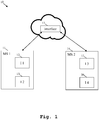
- FIG. 1 a block diagram of an exemplary embodiment of a measurement cloud setup 10 for coupling measurement device settings across multiple instruments 12, 13, 15, 16 and/or measurement sites 11, 14 is shown.
- the measurement cloud setup 10 comprises a first measurement site 11 comprising a first instrument 12 and a second instrument 13, a second measurement site 14 comprising a third instrument 15 and a fourth instrument 16, and an interface 17, through which the respective instruments and/or measurement sites being part of the coupling are defined especially by a user.
- the interface 17 may especially comprise at least one of a controller, a management software, a cloud service, or any combination thereof.
- the interface 17 may be configured to receive a changed setting and to send instructions to each coupled instrument 12, 13, 15, 16 and/or measurement site 11, 14 to take the respective new setting.
- the coupled instruments 12, 13, 15, 16 and/or measurement sites 11, 14 may especially be configured to receive and implement a setting change.
- the coupled instruments 12, 13, 15, 16 and/or measurement sites 11, 14 may especially be configured to receive and implement a setting change by providing permission to the interface 17 to make the setting change.
- the coupled instruments 12, 13, 15, 16 and/or measurement sites 11, 14 may especially be configured to send a response to the respective cloud stating a certain status.
- the certain status may preferably comprise at least one of an okay, a not-okay, an acknowledgment, or a non-acknowledgment.
- IP address changes may preferably not be propagated across the respective cloud.
- the groups of settings may preferably comprise defined offsets for specific settings.
- the defined offsets may especially comprise at least a frequency offset.
- a user changes a setting with respect to the third instrument 15 of the second measurement site 14. Accordingly, all other instruments, exemplarily the first instrument 12 and the second instrument 13 of the first measurement site 11, and the fourth instrument 16 of the second measurement site 14, take this change.
- the above-mentioned cloud service may especially comprise a dashboard preferably for displaying the respective settings and/or the respective measurements results.
- the dashboard may especially be a measurement dashboard for a measurement site.
- a measurement site may be defined of more than one measurement instrument.
- it may be created access on the cloud or cloud service, respectively, to said measurement site, but especially not other measurement sites.
- said access comprises or is a web-based dashboard allowing restricted access to multiple authenticated users.
- Said users may be controlled and/or restricted by the respective administrator of the measurement site.
- a software on a respective remote user's computer may preferably be a password-based web interface for user management.
- said web-based dashboard may be configured to show at least one of the respective measurement setup, the respective measurement displays, measurement data belonging to the respective measurement site, or any combination thereof.
- the instruments 12, 13, 15, 16 and/or the measurement sites 11, 14 can be distant from each other.
- the invention allows for an accelerated operation because of all settings of the coupled instruments and/or measurement sites can be updated automatically.
- sources of errors can significantly be reduced because instruments and/or measurement sites cannot differently be configured in an erroneous manner.
- instruments and/or measurement sites can be coupled in a simple and highly efficient manner.
- the inventions provides the advantage that IP addresses or the like have not to be configured, which further increases efficiency.
- the cloud service especially allows for a synchronization of the respective settings between the instruments and/or the measurement sites.
- the cloud service may especially be configured to translate the settings with respect to available instruments and/or measurement sites. Additionally, the cloud service may especially comprise a translation logic for translating the settings.
- the translation logic can be updated in a simple and highly efficient manner.
- a cloud-based measurement platform for identifying a device, especially a measurement device or a platform device, a connecting the device with a device profile in a measurement site.
- Said cloud-based measurement platform may comprise at least one measurement site comprising at least one device profile, especially at least one measurement device profile.
- the device profile may comprise at least configurations and/or settings. Additionally or alternatively, the device profile may comprise particular data, waveforms, scripts, saved settings, current configuration, or any combination thereof.
- the device may comprise or be a signal analyzer or a signal generator.
- the cloud-based measurement platform may comprise a device to be associated with the at least one measurement site.
- the respective cloud or a cloud service, respectively, of the cloud-based measurement platform may especially be configured to authenticate devices, wherein the respective authentication preferably links the respective device with the corresponding measurement site and the profile of the respective device in the corresponding measurement site.
- an optical code preferably a QR code
- a dongle preferably an USB (Universal Serial Bus) dongle, may provide the respective key especially for said authentication.
- the device may be configured to communicate with the cloud or the cloud service, respectively.
- the cloud or the cloud service may be configured to provide the desired or correct device profile, especially measurement device profile.
- the authentication may be mediated by a smartphone application in combination with at least one optical code such as an QR code generated by the respective device or measurement site.
- the authentication may comprise questioning the respective user which profile, especially measurement profile, should be used for the respective device to be connected or associated or a new profile should be generated.
- the authentication may comprise using the type of the respective device to suggest possible profiles, especially measurement profiles, for the device to be connected or associated.
- the dongle may be configured to provide the respective key for the corresponding measurement site and/or for a particular profile, preferably a particular measurement profile, within the corresponding measurement site.
- FIG. 2 an exemplary embodiment of a cloud-based measurement platform 20 for the first aspect of the invention is shown.
- the cloud-based measurement platform 20 comprises a cloud service 21, a first measurement site 22 comprising a first measurement device 23 and a QR (Quick Response) code 24, a platform device 25, preferably a mobile device, more preferably a mobile phone, most preferably a smartphone, a second measurement site 26 comprising a second measurement device 27, and a dongle 28 preferably in the form of an USB stick.
- a QR Quick Response
- the platform device 25 may be configured to scan an optical code such as the QR code 24 of the measurement site 22 or of the device 23.
- said optical code may be a printed code or a code displayed on a display of the measurement site 22 or of the device 23, respectively.
- the platform device 25 may be configured to synchronize with the cloud service 21.
- the platform device 25 may be configured to use a wireless communication technique such as NFC (Near Field Communication) with respect to the measurement site 22 or the device 23 and to synchronize with the cloud service 21.
- a wireless communication technique such as NFC (Near Field Communication)
- a device especially a measurement device such as the device 27, with respect to a measurement site such as the measurement site 26, an USB stick or dongle, respectively, such as the USB stick 28 is provided for the measurement site 26.
- the device 27 is configured to read the USB stick 28 and to connect itself with the respective cloud measurement site especially on the basis of the information and/or key read from the USB stick 28.
- the measurement cloud setup may comprise a management software and/or a cloud service that allows the user to define the instruments within measurement sites and/or measurement sites that are part of the respective coupling.
- the measurement sites may be connected by a network especially comprising a network router and/or a server.
- the management software and/or the cloud service may be configured to receive a setting from at least one of the measurement sites and/or to receive a setting from an user interface for the management software and/or for the cloud service.
- management software and/or the cloud service may be configured to send instructions to at least one of the coupled instruments and/or the coupled measurement sites especially in order to propose the respective setting.
- the coupled measurement instruments may be configured to receive and/or to implement the setting if possible and/or to provide the option to implement the setting.
- the option to implement the setting can be at cloud or cloud service, respectively, management software, or anywhere at measurement site.
- the cloud or the cloud service, respectively, and/or the management software may be configured to compare the respective measurements of different devices under test.
- this allows for averaging over many devices under test and/or getting statistical information about device under test variation. Further advantageously, this can be particularly helpful if a reference device under test is used.
- each measurement setup with respect to the multiple instruments and/or measurement sites may be configured to measure at least one device under test and to provide the corresponding results to the cloud or cloud service, respectively, and/or management software.
- the current settings profile may be stored on the cloud or the cloud service, respectively.
- the cloud or the cloud service, respectively may provide changes and instructions to the coupled sites.
- At least one, preferably each, of the coupled measurement instruments may be configured to check if it is capable of taking a setting, especially a setting change, and to acknowledge or reject accordingly.
- At least one of the measurement sites may be a reference measurement site that can make the changes. Additionally, the remaining measurement sites and/or instruments may only clone the changes from said reference measurement site.
- At least one, preferably each, of the said members may be configured to provide an option on the respective measurement instruments, cloud, cloud service, management software, or any combination thereof for the user to accept or not to accept instruments.
- each measurement instrument in a measurement site has a role and any cloning of measurement settings goes to such instruments especially of said role in other sites.
- the changed settings may be taken from measurement site, cloud or cloud service, respectively, and/or management software. It is further noted that this especially allows for creating digital twins or a kind thereof.
- the cloud or cloud service, respectively, and/or the measurement software may be configured to calculate a list of measurement sites where this setting has to be changed.
- the cloud or cloud service, respectively, and/or the management software may comprise capability information for each of the instruments at the at least one coupled measurement site. Additionally, the cloud or cloud service, respectively, and/or the management software may further be configured to know which sites can accept settings set by users.
- groups of settings may comprise defined offsets for specific settings, exemplarily a frequency offset.
- the measurement sites and/or measurement instruments may be configured to clone settings in real time. Additionally or alternatively, the measurement sites and/or measurement instruments may be configured to perform measurements simultaneously.
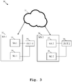
- FIG. 3 a further exemplary embodiment 30 of the first aspect of the invention is depicted.
- the measurement cloud setup 30 comprises a cloud service 31, a first measurement site 32 comprising a first signal analyzer 33 and a first signal generator 34, a first device under test 35 connected to the first signal generator 34 and to the first signal analyzer 33, a second measurement site 36 comprising a second signal analyzer 37 and a second signal generator 38, and a second device under test 39 connected to the second signal generator 38 and the second signal analyzer 37.
- first measurement site 32 and the second measurement site 36 are coupled to each other with the aid of the cloud service 31.
- the respective measurement results of the first signal analyzer 33 and the second signal analyzer 37 are compared to each other and/or to respective reference values.
- said respective measurement results may further be processed on the basis of at least one mathematical function.
- the cloud service 31 may be configured to perform said comparison and/or said calculation.
- the corresponding result of said comparison and/or said calculation may be displayed on any display of the measurement instruments, especially the coupled measurement instruments.
- the corresponding result of said comparison and/or said calculation may be displayed on a dashboard, preferably a cloud dashboard.
- the cloud service 31 may comprise a dashboard, wherein the dashboard may be configured to display said corresponding result.
- Fig. 4 shows a flow chart of an embodiment of the inventive method for handling a measurement cloud setup for coupling measurement device settings across multiple instruments and/or measurement sites.
- the respective instruments and/or measurement sites are defined as being part of the coupling of measurement device settings across multiple instruments and/or measurement sites through an interface of the measurement cloud setup for said coupling.
- all members of the coupling are provided with instructions to inform the respective cloud of any setting changes.
- the interface may comprise at least one of a controller, a management software, a cloud service, or any combination thereof.
- the method may comprise the step of receiving a changed setting especially with the aid of the interface.
- the method may comprise the step of sending instructions to each coupled instrument and/or measurement site to take the respective new setting especially with the aid of the interface.
- the method may comprise the step of receiving and implementing a setting change especially with the aid of the coupled instruments and/or measurement sites.
- the method may comprise the step of receiving and implementing a setting change by providing permission to the interface to make the setting change especially with the aid of the coupled instruments and/or measurement sites.
- the method may comprise the step of sending a response to the respective cloud stating a certain status especially with the aid of the coupled instruments and/or measurement sites.
- the certain status comprises at least one of an okay, a not-okay, an acknowledgment, or a non-acknowledgment.
- the method may further comprise the step defining groups of settings to be coupled such that not all settings are propagated.
- IP address changes may not be propagated across the respective cloud.
- the method may further comprise the step of not propagating IP address changes across the respective cloud.
- the groups of settings may especially comprise defined offsets for specific settings.
- the defined offsets may especially comprise at least a frequency offset.
Landscapes
- Engineering & Computer Science (AREA)
- Computer Networks & Wireless Communication (AREA)
- Computer Security & Cryptography (AREA)
- Signal Processing (AREA)
- Computer Hardware Design (AREA)
- General Engineering & Computer Science (AREA)
- Theoretical Computer Science (AREA)
- Computing Systems (AREA)
- General Physics & Mathematics (AREA)
- Physics & Mathematics (AREA)
- Software Systems (AREA)
- Health & Medical Sciences (AREA)
- General Health & Medical Sciences (AREA)
- Bioethics (AREA)
- Medical Informatics (AREA)
- Human Computer Interaction (AREA)
- Arrangements For Transmission Of Measured Signals (AREA)
- User Interface Of Digital Computer (AREA)
- Telephone Function (AREA)
Abstract
Description
- The invention relates to a measurement cloud setup for coupling measurement device settings across multiple instruments and/or measurement sites and a method for handling such a measurement cloud setup.
- Generally, in times of an increasing number of measurement instruments and measurement sites being distant from one another, there is a growing need of a measurement cloud setup for coupling measurement device settings across multiple instruments and/or measurement sites and a method for handling such a measurement cloud setup in order to ensure highly efficient measurements.
- Unfortunately, neither a measurement cloud setup for coupling measurement device settings across multiple instruments and/or measurement sites nor a method for handling a measurement cloud setup for coupling measurement device settings across multiple instruments and/or measurement sites is known.
- Accordingly, there is the object to provide an over-the-air measurement chamber and an over-the-air measurement method in order to allow for performing measurements, especially measurements regarding wireless connectivity capabilities under different temperature conditions, with respect to a device under test in a flexible manner, thereby ensuring a high accuracy and efficiency of the measurement.
- This object is solved by the features of
claim 1 for a measurement cloud setup for coupling measurement device settings across multiple instruments and/or measurement sites and the features ofclaim 15 for a method for handling such a measurement cloud setup. The dependent claims contain further developments. - According to a first aspect of the invention, a measurement cloud setup for coupling measurement device settings across multiple instruments and/or measurement sites is provided. The measurement cloud setup comprises an interface, through which the respective instruments and/or measurement sites being part of the coupling are defined. Advantageously, for instance, a high efficiency can ensured with special respect to measurement instruments and/or measurement sites being distant from one another.
- In this context, it is noted that the measurement cloud setup may especially comprise the multiple instruments and/or measurement sites.
- According to a first preferred implementation form of the first aspect of the invention, the respective instruments and/or measurement sites being part of the coupling are defined by a user. Advantageously, for example, a user can directly control the setup.
- According to a second preferred implementation form of the first aspect of the invention, the interface comprises at least one of a controller, a management software, a cloud service, or any combination thereof. Advantageously, for instance, the interface may allow for an efficient management of the setup.
- According to a further preferred implementation form of the first aspect of the invention, all members of the coupling are provided with instructions to inform the respective cloud of any setting changes. Advantageously, for instance, efficiency can further be increased.
- Alternatively, it is noted that all members of the coupling may provide instructions to inform the respective cloud of any setting changes.
- It is further noted that the setting changes especially relate to any setting change with respect to the instruments and/or the measurement sites.
- According to a further preferred implementation form of the first aspect of the invention, the interface is configured to receive a changed setting. Advantageously, for example, a setting change can be received and processed in a highly efficient manner.
- In this context, it is noted that said changed setting may especially be inputted by a user.
- According to a further preferred implementation form of the first aspect of the invention, the interface is configured to send instructions to each coupled instrument and/or measurement site to take the respective new setting. Advantageously, for instance, efficiency can further be increased.
- According to a further preferred implementation form of the first aspect of the invention, the coupled instruments and/or measurement sites are configured to receive and implement a setting change. Advantageously, for example, setting changes can be implemented in a highly efficient manner.
- According to a further preferred implementation form of the first aspect of the invention, the coupled instruments and/or measurement sites are configured to receive and implement a setting change by providing permission to the interface to make the setting change. Advantageously, for instance, efficiency can further be increased.
- According to a further preferred implementation form of the first aspect of the invention, the coupled instruments and/or measurement sites are configured to send a response to the respective cloud stating a certain status. Advantageously, for example, a status can be detected in a highly efficient manner.
- According to a further preferred implementation form of the first aspect of the invention, the certain status comprises at least one of an okay, a not-okay, an acknowledgment, or a non-acknowledgment. Advantageously, for instance, complexity can be reduced, thereby increasing efficiency.
- According to a further preferred implementation form of the first aspect of the invention, groups of settings to be coupled are defined such that not all settings are propagated. Advantageously, the interface may especially be configured to define said groups of settings.
- According to a further preferred implementation form of the first aspect of the invention, IP (Internet Protocol) address changes are not propagated across the respective cloud. Advantageously, for instance, simplicity of configuration can be increased, which leads to an increased efficiency.
- According to a further preferred implementation form of the first aspect of the invention, groups of settings comprise defined offsets for specific settings. Advantageously, for example, complexity can be reduced, thereby increasing efficiency.
- According to a further preferred implementation form of the first aspect of the invention, the defined offsets comprise at least a frequency offset. Advantageously, for instance, efficiency can further be increased.
- According to a second aspect of the invention, a method for handling a measurement cloud setup for coupling measurement device settings across multiple instruments and/or measurement sites is provided. The method comprises the step of defining the respective instruments and/or measurement sites as being part of the coupling through an interface of the measurement cloud setup. Advantageously, for instance, a high efficiency can ensured with special respect to measurement instruments and/or measurement sites being distant from one another.
- Exemplary embodiments of the invention are now further explained with respect to the drawings by way of example only, and not for limitation. In the drawings:
- Fig. 1
- shows an exemplary embodiment of the first aspect of the invention;
- Fig. 2
- shows a further exemplary embodiment with respect to the first aspect of the invention;
- Fig. 3
- shows a further exemplary embodiment of the first aspect of the invention;
- Fig. 4
- shows a flow chart of an embodiment of the second aspect of the invention;
- Fig. 5
- shows a flow chart of a further embodiment of the second aspect of the invention; and
- Fig. 6
- shows a flow chart of a further embodiment of the second aspect of the invention.
- With respect to
Fig. 1 , a block diagram of an exemplary embodiment of ameasurement cloud setup 10 for coupling measurement device settings acrossmultiple instruments measurement sites - According to
Fig. 1 , themeasurement cloud setup 10 comprises afirst measurement site 11 comprising afirst instrument 12 and asecond instrument 13, asecond measurement site 14 comprising athird instrument 15 and afourth instrument 16, and aninterface 17, through which the respective instruments and/or measurement sites being part of the coupling are defined especially by a user. - In this context, it is noted that the
interface 17 may especially comprise at least one of a controller, a management software, a cloud service, or any combination thereof. - Furthermore, all
members interface 17. - Moreover, it is noted that the
interface 17 may be configured to receive a changed setting and to send instructions to each coupledinstrument measurement site - Additionally or alternatively, the coupled
instruments measurement sites - Furthermore, the coupled
instruments measurement sites interface 17 to make the setting change. - In addition to this or as an alternative, the coupled
instruments measurement sites - In this context, the certain status may preferably comprise at least one of an okay, a not-okay, an acknowledgment, or a non-acknowledgment.
- It might be particularly advantageous if groups of settings to be coupled are defined such that not all settings are propagated.
- Furthermore, IP address changes may preferably not be propagated across the respective cloud.
- With respect to the groups of settings, it is noted that the groups of settings may preferably comprise defined offsets for specific settings.
- In this context, it is further noted that the defined offsets may especially comprise at least a frequency offset.
- Now, an exemplary use case with respect to the
measurement cloud setup 10 according toFig. 1 is described in the following. - Exemplarily, a user changes a setting with respect to the
third instrument 15 of thesecond measurement site 14. Accordingly, all other instruments, exemplarily thefirst instrument 12 and thesecond instrument 13 of thefirst measurement site 11, and thefourth instrument 16 of thesecond measurement site 14, take this change. - In other words, all coupled instruments and/or measurement sites are automatically updated with respect to a setting change. It is further noted that the above-mentioned cloud service may especially comprise a dashboard preferably for displaying the respective settings and/or the respective measurements results.
- With respect to the dashboard, it is noted that the dashboard may especially be a measurement dashboard for a measurement site. In this context, a measurement site may be defined of more than one measurement instrument.
- Furthermore, it may be created access on the cloud or cloud service, respectively, to said measurement site, but especially not other measurement sites.
- It might be particularly advantageous if said access comprises or is a web-based dashboard allowing restricted access to multiple authenticated users. Said users may be controlled and/or restricted by the respective administrator of the measurement site.
- It is noted that in this manner, direct network access to the site is advantageously not required. Further advantageously, a software on a respective remote user's computer may preferably be a password-based web interface for user management.
- Moreover, said web-based dashboard may be configured to show at least one of the respective measurement setup, the respective measurement displays, measurement data belonging to the respective measurement site, or any combination thereof.
- In accordance with the invention, it is additionally noted that the
instruments measurement sites - In addition to this, it is noted that the invention allows for an accelerated operation because of all settings of the coupled instruments and/or measurement sites can be updated automatically.
- Further advantageously, sources of errors can significantly be reduced because instruments and/or measurement sites cannot differently be configured in an erroneous manner.
- As a further advantage, especially due to the cloud service, instruments and/or measurement sites can be coupled in a simple and highly efficient manner.
- In addition to this, the inventions provides the advantage that IP addresses or the like have not to be configured, which further increases efficiency.
- Again, with respect to the cloud service, it is noted that the cloud service especially allows for a synchronization of the respective settings between the instruments and/or the measurement sites.
- Furthermore, the cloud service may especially be configured to translate the settings with respect to available instruments and/or measurement sites. Additionally, the cloud service may especially comprise a translation logic for translating the settings.
- In this context, it might be particularly advantageous that the translation logic can be updated in a simple and highly efficient manner.
- In addition to this, with respect to the instruments and/or the measurement sites, it is noted that no updates of the instruments and/or the measurement sites may be needed, even in the case that new instruments and/or measurement sites should be supported.
- With respect to the first aspect of the invention, it is generally noted that it might be particularly advantageous to provide a cloud-based measurement platform for identifying a device, especially a measurement device or a platform device, a connecting the device with a device profile in a measurement site.
- Said cloud-based measurement platform may comprise at least one measurement site comprising at least one device profile, especially at least one measurement device profile. The device profile may comprise at least configurations and/or settings. Additionally or alternatively, the device profile may comprise particular data, waveforms, scripts, saved settings, current configuration, or any combination thereof. Furthermore, the device may comprise or be a signal analyzer or a signal generator.
- Moreover, the cloud-based measurement platform may comprise a device to be associated with the at least one measurement site.
- The respective cloud or a cloud service, respectively, of the cloud-based measurement platform may especially be configured to authenticate devices, wherein the respective authentication preferably links the respective device with the corresponding measurement site and the profile of the respective device in the corresponding measurement site. In this context, especially with respect to said authentication, an optical code, preferably a QR code, may be scanned. Additionally or alternatively, a dongle, preferably an USB (Universal Serial Bus) dongle, may provide the respective key especially for said authentication.
- With respect to the device, it is noted that the device may be configured to communicate with the cloud or the cloud service, respectively. In this context, the cloud or the cloud service, respectively, may be configured to provide the desired or correct device profile, especially measurement device profile.
- With respect to the above-mentioned authentication, it is noted that the authentication may be mediated by a smartphone application in combination with at least one optical code such as an QR code generated by the respective device or measurement site.
- In addition to this or as an alternative, the authentication may comprise questioning the respective user which profile, especially measurement profile, should be used for the respective device to be connected or associated or a new profile should be generated.
- Further additionally or further alternatively, the authentication may comprise using the type of the respective device to suggest possible profiles, especially measurement profiles, for the device to be connected or associated.
- Again, with respect to the dongle, preferably the USB dongle, it is noted that the dongle may be configured to provide the respective key for the corresponding measurement site and/or for a particular profile, preferably a particular measurement profile, within the corresponding measurement site.
- Now, with respect to
Fig. 2 , an exemplary embodiment of a cloud-basedmeasurement platform 20 for the first aspect of the invention is shown. - According to
Fig. 2 , the cloud-basedmeasurement platform 20 comprises acloud service 21, afirst measurement site 22 comprising afirst measurement device 23 and a QR (Quick Response)code 24, aplatform device 25, preferably a mobile device, more preferably a mobile phone, most preferably a smartphone, asecond measurement site 26 comprising asecond measurement device 27, and adongle 28 preferably in the form of an USB stick. - In a first use case of identifying a device, especially a measurement device such as the
device 23, with respect to a measurement site such as themeasurement site 22, theplatform device 25 may be configured to scan an optical code such as theQR code 24 of themeasurement site 22 or of thedevice 23. In this context, said optical code may be a printed code or a code displayed on a display of themeasurement site 22 or of thedevice 23, respectively. In addition to this, theplatform device 25 may be configured to synchronize with thecloud service 21. - Additionally or alternatively, in a second use case of identifying a device, especially a measurement device such as the
device 23, with respect to a measurement site such as themeasurement site 22, theplatform device 25 may be configured to use a wireless communication technique such as NFC (Near Field Communication) with respect to themeasurement site 22 or thedevice 23 and to synchronize with thecloud service 21. - Furthermore, in a third use case of identifying a device, especially a measurement device such as the
device 27, with respect to a measurement site such as themeasurement site 26, an USB stick or dongle, respectively, such as theUSB stick 28 is provided for themeasurement site 26. In this context, thedevice 27 is configured to read theUSB stick 28 and to connect itself with the respective cloud measurement site especially on the basis of the information and/or key read from theUSB stick 28. - Again, with respect to the measurement cloud setup for coupling measurement device settings across multiple instruments and/or measurement sites, it is generally noted that the measurement cloud setup may comprise a management software and/or a cloud service that allows the user to define the instruments within measurement sites and/or measurement sites that are part of the respective coupling.
- The measurement sites may be connected by a network especially comprising a network router and/or a server.
- The management software and/or the cloud service may be configured to receive a setting from at least one of the measurement sites and/or to receive a setting from an user interface for the management software and/or for the cloud service.
- Furthermore, the management software and/or the cloud service may be configured to send instructions to at least one of the coupled instruments and/or the coupled measurement sites especially in order to propose the respective setting.
- Moreover, the coupled measurement instruments may be configured to receive and/or to implement the setting if possible and/or to provide the option to implement the setting. In this context, the option to implement the setting can be at cloud or cloud service, respectively, management software, or anywhere at measurement site.
- It is further noted that the cloud or the cloud service, respectively, and/or the management software may be configured to compare the respective measurements of different devices under test. Advantageously, this allows for averaging over many devices under test and/or getting statistical information about device under test variation. Further advantageously, this can be particularly helpful if a reference device under test is used.
- Furthermore, each measurement setup with respect to the multiple instruments and/or measurement sites may be configured to measure at least one device under test and to provide the corresponding results to the cloud or cloud service, respectively, and/or management software.
- Moreover, it might be particularly advantageous if all members of coupling provided instructions to inform the cloud or the cloud service, respectively, and/or the management software of any setting changes. In this context, the current settings profile may be stored on the cloud or the cloud service, respectively. In addition to this, the cloud or the cloud service, respectively, may provide changes and instructions to the coupled sites.
- It is further noted that at least one, preferably each, of the coupled measurement instruments may be configured to check if it is capable of taking a setting, especially a setting change, and to acknowledge or reject accordingly.
- Furthermore, at least one of the measurement sites may be a reference measurement site that can make the changes. Additionally, the remaining measurement sites and/or instruments may only clone the changes from said reference measurement site.
- Again, with respect to all members of the coupling, it is noted that at least one, preferably each, of the said members may be configured to provide an option on the respective measurement instruments, cloud, cloud service, management software, or any combination thereof for the user to accept or not to accept instruments.
- It might be particularly advantageous if each measurement instrument in a measurement site has a role and any cloning of measurement settings goes to such instruments especially of said role in other sites.
- It is noted that after predefining coupled measurement sites, some of which may take the changed settings, other will not. The changed settings may be taken from measurement site, cloud or cloud service, respectively, and/or management software. It is further noted that this especially allows for creating digital twins or a kind thereof.
- Furthermore, on the basis of a changed setting and/or a measurement result of changed setting and/or capability information, the cloud or cloud service, respectively, and/or the measurement software may be configured to calculate a list of measurement sites where this setting has to be changed.
- Moreover, the cloud or cloud service, respectively, and/or the management software may comprise capability information for each of the instruments at the at least one coupled measurement site. Additionally, the cloud or cloud service, respectively, and/or the management software may further be configured to know which sites can accept settings set by users.
- It might be particularly advantageous if groups of setting types to be coupled are defined such that not all settings are propagated.
- In addition to this or as an alternative, groups of settings may comprise defined offsets for specific settings, exemplarily a frequency offset.
- With respect to the measurement sites and/or measurement instruments, it is noted that the measurement sites and/or measurement instruments may be configured to clone settings in real time. Additionally or alternatively, the measurement sites and/or measurement instruments may be configured to perform measurements simultaneously.
- Now, with respect to
Fig. 3 , a furtherexemplary embodiment 30 of the first aspect of the invention is depicted. - According to
Fig. 3 , themeasurement cloud setup 30 comprises acloud service 31, afirst measurement site 32 comprising afirst signal analyzer 33 and afirst signal generator 34, a first device undertest 35 connected to thefirst signal generator 34 and to thefirst signal analyzer 33, asecond measurement site 36 comprising asecond signal analyzer 37 and asecond signal generator 38, and a second device undertest 39 connected to thesecond signal generator 38 and thesecond signal analyzer 37. - In this context, the
first measurement site 32 and thesecond measurement site 36 are coupled to each other with the aid of thecloud service 31. - Furthermore, the respective measurement results of the
first signal analyzer 33 and thesecond signal analyzer 37 are compared to each other and/or to respective reference values. In addition to this or as an alternative, said respective measurement results may further be processed on the basis of at least one mathematical function. In this context, thecloud service 31 may be configured to perform said comparison and/or said calculation. - It is further noted that the corresponding result of said comparison and/or said calculation may be displayed on any display of the measurement instruments, especially the coupled measurement instruments.
- In addition to this or as an alternative, the corresponding result of said comparison and/or said calculation may be displayed on a dashboard, preferably a cloud dashboard. In other words, the
cloud service 31 may comprise a dashboard, wherein the dashboard may be configured to display said corresponding result. - Finally,
Fig. 4 shows a flow chart of an embodiment of the inventive method for handling a measurement cloud setup for coupling measurement device settings across multiple instruments and/or measurement sites. In afirst step 100, the respective instruments and/or measurement sites are defined as being part of the coupling of measurement device settings across multiple instruments and/or measurement sites through an interface of the measurement cloud setup for said coupling. Then, in asecond step 101, all members of the coupling are provided with instructions to inform the respective cloud of any setting changes. - In this context, it might be particularly advantageous if the respective instruments and/or measurement sites being part of the coupling are defined by a user.
- It is further noted that the interface may comprise at least one of a controller, a management software, a cloud service, or any combination thereof.
- Furthermore, in accordance with
Fig. 5 , the method may comprise the step of receiving a changed setting especially with the aid of the interface. - Moreover, the method may comprise the step of sending instructions to each coupled instrument and/or measurement site to take the respective new setting especially with the aid of the interface.
- In addition to this or as an alternative, the method may comprise the step of receiving and implementing a setting change especially with the aid of the coupled instruments and/or measurement sites.
- It is further noted that the method may comprise the step of receiving and implementing a setting change by providing permission to the interface to make the setting change especially with the aid of the coupled instruments and/or measurement sites.
- Additionally or alternatively, the method may comprise the step of sending a response to the respective cloud stating a certain status especially with the aid of the coupled instruments and/or measurement sites.
- In this context, it is noted that it might be particularly advantageous if the certain status comprises at least one of an okay, a not-okay, an acknowledgment, or a non-acknowledgment.
- Moreover, in accordance with
Fig. 6 , the method may further comprise the step defining groups of settings to be coupled such that not all settings are propagated. - It is further noted that IP address changes may not be propagated across the respective cloud. In other words, the method may further comprise the step of not propagating IP address changes across the respective cloud.
- With respect to the groups of settings, it is noted that the groups of settings may especially comprise defined offsets for specific settings.
- In this context, the defined offsets may especially comprise at least a frequency offset.
- While various embodiments of the present invention have been described above, it should be understood that they have been presented by way of example only, and not limitation. Numerous changes to the disclosed embodiments can be made in accordance with the disclosure herein without departing from the spirit or scope of the invention. Thus, the breadth and scope of the present invention should not be limited by any of the above described embodiments. Rather, the scope of the invention should be defined in accordance with the following claims and their equivalents.
- Although the invention has been illustrated and described with respect to one or more implementations, equivalent alterations and modifications will occur to others skilled in the art upon the reading and understanding of this specification and the annexed drawings. In addition, while a particular feature of the invention may have been disclosed with respect to only one of several implementations, such feature may be combined with one or more other features of the other implementations as may be desired and advantageous for any given or particular application.
Claims (15)
- A measurement cloud setup (10) for coupling measurement device settings across multiple instruments (12, 13, 15, 16) and/or measurement sites (11, 14), the measurement cloud setup (10) comprising:
an interface (17),
through which the respective instruments (12, 13, 15, 16) and/or measurement sites (11, 14) being part of the coupling are defined. - The measurement cloud setup (10) according to claim 1, wherein the respective instruments (12, 13, 15, 16) and/or measurement sites (11, 14) being part of the coupling are defined by a user.
- The measurement cloud setup (10) according to claim 1 or 2,
wherein the interface (17) comprises at least one of a controller, a management software, a cloud service, or any combination thereof. - The measurement cloud setup (10) according to any of the claims 1 to 3,
wherein all members (11, 12, 13, 14, 15, 16) of the coupling are provided with instructions to inform the respective cloud of any setting changes. - The measurement cloud setup (10) according to any of the claims 1 to 4,
wherein the interface (17) is configured to receive a changed setting. - The measurement cloud setup (10) according claim 5,
wherein the interface (17) is configured to send instructions to each coupled instrument (12, 13, 15, 16) and/or measurement site (11, 14) to take the respective new setting. - The measurement cloud setup (10) according to any of the claims 1 to 6,
wherein the coupled instruments (12, 13, 15, 16) and/or measurement sites (11, 14) are configured to receive and implement a setting change. - The measurement cloud setup (10) according to any of the claims 1 to 7,
wherein the coupled instruments (12, 13, 15, 16) and/or measurement sites (11, 14) are configured to receive and implement a setting change by providing permission to the interface (17) to make the setting change. - The measurement cloud setup (10) according to any of the claims 1 to 8,
wherein the coupled instruments (12, 13, 15, 16) and/or measurement sites (11, 14) are configured to send a response to the respective cloud stating a certain status. - The measurement cloud setup (10) according to claim 9, wherein the certain status comprises at least one of an okay, a not-okay, an acknowledgment, or a non-acknowledgment.
- The measurement cloud setup (10) according to any of the claims 1 to 10,
wherein groups of settings to be coupled are defined such that not all settings are propagated. - The measurement cloud setup (10) according to any of the claims 1 to 11,
wherein IP address changes are not propagated across the respective cloud. - The measurement cloud setup (10) according to any of the claims 1 to 12,
wherein groups of settings comprise defined offsets for specific settings. - The measurement cloud setup (10) according claim 13,
wherein the defined offsets comprise at least a frequency offset. - A method for handling a measurement cloud setup (10) for coupling measurement device settings across multiple instruments (12, 13, 15, 16) and/or measurement sites (11, 14), the method comprising the step of:
defining the respective instruments (12, 13, 15, 16) and/or measurement sites (11, 14) as being part of the coupling through an interface (17) of the measurement cloud setup (10).
Priority Applications (2)
| Application Number | Priority Date | Filing Date | Title |
|---|---|---|---|
| CN201911043095.4A CN112087729B (en) | 2019-06-13 | 2019-10-30 | Measurement cloud mechanism and corresponding processing method for coupling measurement equipment across multiple instruments and/or measurement sites |
| US16/680,173 US12348916B2 (en) | 2019-06-13 | 2019-11-11 | Measurement cloud setup for coupling measurement device settings across multiple instruments and/or measurement sites and corresponding handling method |
Applications Claiming Priority (1)
| Application Number | Priority Date | Filing Date | Title |
|---|---|---|---|
| EP19179849.5A EP3751532B1 (en) | 2019-06-13 | 2019-06-13 | Remote access and control system and corresponding method |
Publications (3)
| Publication Number | Publication Date |
|---|---|
| EP3751533A1 true EP3751533A1 (en) | 2020-12-16 |
| EP3751533B1 EP3751533B1 (en) | 2023-04-26 |
| EP3751533B8 EP3751533B8 (en) | 2023-07-05 |
Family
ID=67001529
Family Applications (3)
| Application Number | Title | Priority Date | Filing Date |
|---|---|---|---|
| EP19179849.5A Active EP3751532B1 (en) | 2019-06-13 | 2019-06-13 | Remote access and control system and corresponding method |
| EP19187201.9A Pending EP3751534A1 (en) | 2019-06-13 | 2019-07-19 | Cloud-based system for making user data available on any platform device in the context of measurement and corresponding handling method |
| EP19187186.2A Active EP3751533B8 (en) | 2019-06-13 | 2019-07-19 | Measurement cloud system for coupling measurement device settings across multiple instruments and/or measurement sites and corresponding handling method |
Family Applications Before (2)
| Application Number | Title | Priority Date | Filing Date |
|---|---|---|---|
| EP19179849.5A Active EP3751532B1 (en) | 2019-06-13 | 2019-06-13 | Remote access and control system and corresponding method |
| EP19187201.9A Pending EP3751534A1 (en) | 2019-06-13 | 2019-07-19 | Cloud-based system for making user data available on any platform device in the context of measurement and corresponding handling method |
Country Status (3)
| Country | Link |
|---|---|
| US (3) | US11303475B2 (en) |
| EP (3) | EP3751532B1 (en) |
| CN (2) | CN112087729B (en) |
Families Citing this family (2)
| Publication number | Priority date | Publication date | Assignee | Title |
|---|---|---|---|---|
| FR3110733B1 (en) * | 2020-05-20 | 2022-05-20 | Byo Networks | Method for controlling a distributed computer system and associated devices |
| US11601428B2 (en) | 2020-12-10 | 2023-03-07 | Cisco Technology, Inc. | Cloud delivered access |
Citations (2)
| Publication number | Priority date | Publication date | Assignee | Title |
|---|---|---|---|---|
| US20140188423A1 (en) * | 2012-12-31 | 2014-07-03 | General Electric Company | Systems and methods for control of a non-destructive testing system |
| WO2016151096A1 (en) * | 2015-03-25 | 2016-09-29 | Ecomesure | Universal communication system for measurement apparatuses, method of communication relating thereto |
Family Cites Families (127)
| Publication number | Priority date | Publication date | Assignee | Title |
|---|---|---|---|---|
| US5075857A (en) * | 1988-03-11 | 1991-12-24 | Maresca Joseph S | Unmanned compliance monitoring device |
| US5530373A (en) * | 1995-01-20 | 1996-06-25 | Fluke Corporation | Method and apparatus for determining and selectively displaying valid measurement information |
| US6968302B1 (en) | 1999-08-11 | 2005-11-22 | Agilent Technologies, Inc. | System and method for remote analysis and control of test and measurement devices |
| DE10018651A1 (en) | 2000-04-14 | 2001-12-20 | Rohde & Schwarz | System for remote control of electronic measuring devices |
| JP2002024670A (en) | 2000-07-07 | 2002-01-25 | Anritsu Corp | Measuring instrument demonstration method and measuring instrument demonstration system using network |
| US6971065B2 (en) | 2000-12-13 | 2005-11-29 | National Instruments Corporation | Automatically configuring a graphical program to publish or subscribe to data |
| US7287230B2 (en) | 2000-12-13 | 2007-10-23 | National Instruments Corporation | Configuring a GUI element to subscribe to data |
| TWI308306B (en) | 2001-07-09 | 2009-04-01 | Matsushita Electric Industrial Co Ltd | Digital work protection system, record/playback device, recording medium device, and model change device |
| US7043393B2 (en) | 2001-08-15 | 2006-05-09 | National Instruments Corporation | System and method for online specification of measurement hardware |
| US7113883B1 (en) * | 2001-08-24 | 2006-09-26 | Vi Technology, Inc. | Test configuration and data management system and associated method for enterprise test operations |
| US7491367B2 (en) * | 2002-06-04 | 2009-02-17 | Applera Corporation | System and method for providing a standardized state interface for instrumentation |
| US20040034496A1 (en) | 2002-08-13 | 2004-02-19 | Correll Jeffrey N. | Displaying functionality of a hardware device in a measurement system |
| US7373403B2 (en) | 2002-08-22 | 2008-05-13 | Agilent Technologies, Inc. | Method and apparatus for displaying measurement data from heterogeneous measurement sources |
| US7231555B2 (en) | 2002-08-22 | 2007-06-12 | Agilent Technologies, Inc. | Method and apparatus to coordinate groups of heterogeneous measurements |
| US7440573B2 (en) | 2002-10-08 | 2008-10-21 | Broadcom Corporation | Enterprise wireless local area network switching system |
| US7284126B2 (en) | 2002-11-12 | 2007-10-16 | Agilent Technologies, Inc. | Device authentication using pre-configured security keys |
| JP3791621B2 (en) * | 2003-01-21 | 2006-06-28 | 富士通株式会社 | Carrier network of virtual network system and communication node of the carrier network |
| US7184917B2 (en) | 2003-02-14 | 2007-02-27 | Advantest America R&D Center, Inc. | Method and system for controlling interchangeable components in a modular test system |
| US20050138149A1 (en) * | 2003-12-23 | 2005-06-23 | Jagjeet Bhatia | Method and system for increasing available user VLAN space |
| US7558273B1 (en) * | 2003-12-23 | 2009-07-07 | Extreme Networks, Inc. | Methods and systems for associating and translating virtual local area network (VLAN) tags |
| US7539862B2 (en) | 2004-04-08 | 2009-05-26 | Ipass Inc. | Method and system for verifying and updating the configuration of an access device during authentication |
| US20070158335A1 (en) * | 2004-12-10 | 2007-07-12 | Mansbery David I | Method and control interface for food preparation on a cooking appliance |
| WO2006076639A1 (en) | 2005-01-13 | 2006-07-20 | National Instruments Corporation | Determining and merging differences between configuration diagrams |
| US7797147B2 (en) * | 2005-04-15 | 2010-09-14 | Microsoft Corporation | Model-based system monitoring |
| US20070038741A1 (en) | 2005-08-12 | 2007-02-15 | Gerholdt Matthew J | Automatically adding an IP address of DNA to a list of instruments displayed to a user by a downloaded instrument management application |
| CN100531101C (en) * | 2007-10-22 | 2009-08-19 | 华为技术有限公司 | A method and device for realizing automatic allocation of end-to-end QinQ service label |
| CN101426004A (en) * | 2007-10-29 | 2009-05-06 | 华为技术有限公司 | Three layer conversation access method, system and equipment |
| US8199149B2 (en) * | 2007-12-13 | 2012-06-12 | Tektronix, Inc. | Automatic generation of frequency domain mask |
| US8305903B1 (en) * | 2008-03-31 | 2012-11-06 | C Speed, Llc | Data acquisition system for test and measurement signals |
| US8230005B2 (en) * | 2009-01-30 | 2012-07-24 | Smart Temps, Llc. | System and method for collecting, transferring and managing quality control data |
| US8918631B1 (en) * | 2009-03-31 | 2014-12-23 | Juniper Networks, Inc. | Methods and apparatus for dynamic automated configuration within a control plane of a switch fabric |
| US8843841B2 (en) | 2009-04-30 | 2014-09-23 | Agilent Technologies, Inc. | System and method for interactive instrument operation and automation |
| US8880736B2 (en) | 2009-07-09 | 2014-11-04 | Simon Cooper | Methods and systems for archiving and restoring securely installed applications on a computing device |
| US8707456B2 (en) * | 2009-07-24 | 2014-04-22 | Broadcom Corporation | Method and system for integrating remote devices into a domestic VLAN |
| US8341725B2 (en) * | 2009-07-30 | 2012-12-25 | Calix, Inc. | Secure DHCP processing for layer two access networks |
| US8892721B2 (en) * | 2009-12-31 | 2014-11-18 | Schneider Electric USA, Inc. | Power monitoring system with proxy server for processing and transforming messages and context-specific caching |
| CN102170385B (en) * | 2010-02-27 | 2014-01-22 | 华为技术有限公司 | Method for transmitting Ethernet frame in Ethernet tree business and provider edge device |
| US9246703B2 (en) * | 2010-06-08 | 2016-01-26 | Brocade Communications Systems, Inc. | Remote port mirroring |
| US9157943B2 (en) * | 2010-08-13 | 2015-10-13 | Tektronix, Inc. | Multi-channel frequency domain test and measurement instrument |
| US8934492B1 (en) * | 2010-09-28 | 2015-01-13 | Adtran, Inc. | Network systems and methods for efficiently dropping packets carried by virtual circuits |
| JP5678800B2 (en) * | 2011-05-23 | 2015-03-04 | 富士通株式会社 | Information processing apparatus, system, and information processing program |
| AU2012270085B2 (en) * | 2011-06-15 | 2015-09-17 | Bae Systems Plc | Data transfer |
| US9172708B2 (en) * | 2011-06-23 | 2015-10-27 | Microsoft Technology Licensing, Llc | Computing system for managing data |
| US9021017B2 (en) * | 2011-09-03 | 2015-04-28 | Barracuda Networks, Inc. | Configuring a plurality of diverse devices/services from an adaptive configuration control hyper-server apparatus |
| US9160633B1 (en) * | 2011-10-07 | 2015-10-13 | Adtran, Inc. | Systems and methods for dynamically learning virtual local area network (VLAN) tags |
| US20130325924A1 (en) * | 2012-06-05 | 2013-12-05 | Mehran Moshfeghi | Method and system for server-assisted remote probing and data collection in a cloud computing environment |
| CN103685022B (en) * | 2012-09-17 | 2016-12-21 | 杭州华三通信技术有限公司 | Message forwarding method and service provider network edge equipment |
| WO2014045316A1 (en) * | 2012-09-20 | 2014-03-27 | Hitachi, Ltd. | Distributed backup system for determining access destination based on multiple performance indexes |
| US9832136B1 (en) * | 2013-01-23 | 2017-11-28 | Liberty Mutual Insurance Company | Streaming software to multiple virtual machines in different subnets |
| US20140236527A1 (en) | 2013-02-21 | 2014-08-21 | Advantest Corporation | Cloud based infrastructure for supporting protocol reconfigurations in protocol independent device testing systems |
| US20140282923A1 (en) * | 2013-03-14 | 2014-09-18 | Motorola Mobility Llc | Device security utilizing continually changing qr codes |
| EP2973071B1 (en) * | 2013-03-15 | 2020-05-06 | Fluke Corporation | Automatic recording and graphing of measurement data |
| JP5854563B2 (en) * | 2013-05-28 | 2016-02-09 | 富士フイルム株式会社 | Image processing method, image processing apparatus, image processing program, and image forming apparatus |
| WO2015028552A1 (en) * | 2013-08-30 | 2015-03-05 | Schneider Electric Danmark A/S | Method for temperature control |
| US10079897B2 (en) * | 2013-10-29 | 2018-09-18 | Telefonaktiebolaget Lm Ericsson (Publ) | Control of a chain of services |
| US9529969B2 (en) * | 2014-01-27 | 2016-12-27 | RDFISolutions, LLC | Event based tracking, health management, and patient and treatment monitoring system |
| US9813489B1 (en) * | 2014-05-13 | 2017-11-07 | Senseware, Inc. | System, method and apparatus for enabling a shared infrastructure |
| DE102014210292B4 (en) | 2014-05-30 | 2026-04-23 | Rohde & Schwarz GmbH & Co. Kommanditgesellschaft | Measuring instrument, measuring system and method for operating a measuring system with rapid synchronization of settings |
| US9875348B2 (en) * | 2014-07-21 | 2018-01-23 | Green Grade Solutions Ltd. | E-learning utilizing remote proctoring and analytical metrics captured during training and testing |
| US9729945B2 (en) * | 2014-09-03 | 2017-08-08 | Oberon, Inc. | Environmental monitor device with database |
| US20160061476A1 (en) * | 2014-09-03 | 2016-03-03 | Oberon, Inc. | Environmental Sensor Device |
| US9785415B2 (en) | 2014-09-29 | 2017-10-10 | National Instruments Corporation | Remote interface to logical instruments |
| CN104301116B (en) * | 2014-10-23 | 2018-04-06 | 上海斐讯数据通信技术有限公司 | A kind of method and system of NFC wireless routers private certification mode |
| US10129799B2 (en) * | 2014-11-03 | 2018-11-13 | Alcatel Lucent | Mobility management for wireless networks |
| US9733306B2 (en) | 2014-11-10 | 2017-08-15 | Analog Devices Global | Remote evaluation tool |
| US10225245B2 (en) * | 2014-11-18 | 2019-03-05 | Auth0, Inc. | Identity infrastructure as a service |
| US10230736B2 (en) * | 2015-01-21 | 2019-03-12 | Onion ID Inc. | Invisible password reset protocol |
| US9836896B2 (en) * | 2015-02-04 | 2017-12-05 | Proprius Technologies S.A.R.L | Keyless access control with neuro and neuro-mechanical fingerprints |
| CN106156454B (en) * | 2015-03-25 | 2018-10-16 | 中国联合网络通信有限公司广州市分公司 | It is health management system arranged based on user authentication and equipment and approaches to IM |
| US10132295B2 (en) * | 2015-05-15 | 2018-11-20 | General Electric Company | Digital system and method for managing a wind farm having plurality of wind turbines coupled to power grid |
| RO131668A2 (en) * | 2015-06-08 | 2017-01-30 | Ixia, A California Corporation | Methods, systems and computer-readable carrier for application session sharing |
| US9960980B2 (en) * | 2015-08-21 | 2018-05-01 | Echostar Technologies International Corporation | Location monitor and device cloning |
| US20170060911A1 (en) * | 2015-08-31 | 2017-03-02 | Synchronoss Technologies, Inc. | Systems and Methods For an Open System Internet of Things Data Hub |
| US10367713B2 (en) * | 2015-10-15 | 2019-07-30 | Fluke Corporation | Cloud based system and method for managing testing configurations for cable test devices |
| US10476735B2 (en) * | 2015-10-31 | 2019-11-12 | Nicira, Inc. | Representation of match conditions in logical pipeline data |
| US9803472B2 (en) * | 2015-11-17 | 2017-10-31 | Rockwell Automation Asia Pacific Business Center Pte. Ltd. | Systems and methods for self configuration of remote terminal units |
| US10551226B2 (en) * | 2015-11-19 | 2020-02-04 | Jabil Inc. | System and method for scalable cloud-based sensor calibration |
| US20170143268A1 (en) * | 2015-11-20 | 2017-05-25 | PhysioWave, Inc. | Aggregation and analysis of scale-based user data and remote user-physiologic device-based user data |
| US9813286B2 (en) * | 2015-11-26 | 2017-11-07 | Industrial Technology Research Institute | Method for virtual local area network fail-over management, system therefor and apparatus therewith |
| US10275962B2 (en) * | 2015-12-14 | 2019-04-30 | Afero, Inc. | Apparatus and method for internet of things (IOT) security lock and notification device |
| US9917903B2 (en) * | 2015-12-28 | 2018-03-13 | Verizon Patent And Licensing Inc. | Internet of things provisioning |
| US11146449B2 (en) * | 2016-02-19 | 2021-10-12 | Intel Corporation | Network architecture for internet-of-things device |
| US11366455B2 (en) * | 2016-05-09 | 2022-06-21 | Strong Force Iot Portfolio 2016, Llc | Methods and systems for optimization of data collection and storage using 3rd party data from a data marketplace in an industrial internet of things environment |
| US11774944B2 (en) * | 2016-05-09 | 2023-10-03 | Strong Force Iot Portfolio 2016, Llc | Methods and systems for the industrial internet of things |
| US9596223B1 (en) * | 2016-05-10 | 2017-03-14 | Logmein, Inc. | Cross-site, TOTP-based two factor authentication |
| JP6380902B2 (en) * | 2016-06-15 | 2018-08-29 | 株式会社エム・クレスト | Remote monitoring system terminal, remote monitoring program, and remote monitoring system |
| US20170373907A1 (en) * | 2016-06-27 | 2017-12-28 | Nokia Solutions And Networks Oy | Use of frequency offset information for wireless networks |
| US10230709B1 (en) * | 2016-06-30 | 2019-03-12 | Juniper Networks, Inc. | Method, system, and apparatus for delegating control over the configuration of multi-tenant network devices |
| DE112016006827T5 (en) * | 2016-07-01 | 2019-03-07 | Intel Corporation | GROUP MANAGEMENT IN RECONFIGURABLE MACHINE TO MACHINE SYSTEMS |
| US10178638B1 (en) * | 2016-07-29 | 2019-01-08 | Senseware, Inc. | System, method and apparatus for sensor control applications |
| US10352299B2 (en) * | 2016-08-05 | 2019-07-16 | General Electric Company | System and method for automatically updating wind turbine data based on component self-identification |
| US10524273B2 (en) * | 2016-09-06 | 2019-12-31 | Telefonaktiebolaget Lm Ericsson (Publ) | Resource configuration of wireless devices |
| US20180137424A1 (en) * | 2016-11-17 | 2018-05-17 | General Electric Company | Methods and systems for identifying gaps in predictive model ontology |
| US10113941B2 (en) * | 2016-12-28 | 2018-10-30 | Dynamic Scientific Production Center USA, Inc. | Method for automatic real-time diagnostics for equipment that generates vibration and static equipment |
| JP6673227B2 (en) * | 2017-01-10 | 2020-03-25 | 横河電機株式会社 | Cloud service control device, cloud service control system, cloud service control method, cloud service control program, and recording medium |
| US10691847B2 (en) * | 2017-01-13 | 2020-06-23 | Sap Se | Real-time damage determination of an asset |
| US12095725B2 (en) * | 2017-03-22 | 2024-09-17 | Amazon Technologies, Inc. | Device credentials management |
| US10868857B2 (en) * | 2017-04-21 | 2020-12-15 | Johnson Controls Technology Company | Building management system with distributed data collection and gateway services |
| US10436615B2 (en) * | 2017-04-24 | 2019-10-08 | Carnegie Mellon University | Virtual sensor system |
| JPWO2018207262A1 (en) * | 2017-05-09 | 2019-12-26 | サン電子株式会社 | Measurement unit and information management system |
| US10756974B2 (en) * | 2017-06-09 | 2020-08-25 | Rockwell Automation Technologies, Inc. | Launch multiple devices firmware update operation from another application with device list context |
| KR102185854B1 (en) * | 2017-09-09 | 2020-12-02 | 애플 인크. | Implementation of biometric authentication |
| US11120012B2 (en) * | 2017-09-27 | 2021-09-14 | Johnson Controls Tyco IP Holdings LLP | Web services platform with integration and interface of smart entities with enterprise applications |
| US20190095517A1 (en) * | 2017-09-27 | 2019-03-28 | Johnson Controls Technology Company | Web services platform with integration of data into smart entities |
| US11368534B2 (en) * | 2017-10-06 | 2022-06-21 | Johnson Controls Tyco IP Holdings LLP | Building management system with device cloud registration and data adaptor |
| US10642598B2 (en) * | 2017-10-06 | 2020-05-05 | Johnson Controls Technology Company | Building management system with plug and play device registration and configuration |
| CN107613512B (en) * | 2017-10-12 | 2023-07-04 | 深圳信息通信研究院 | Automatic calibration system of LTE digital mobile communication comprehensive tester |
| US10476751B2 (en) * | 2017-10-19 | 2019-11-12 | Microsoft Technology Licensing, Llc | IoT cloud to cloud architecture |
| TW201923496A (en) * | 2017-11-20 | 2019-06-16 | 財團法人資訊工業策進會 | Data collecting system based on distributed architecture and operation method thereof |
| WO2019129688A1 (en) * | 2017-12-27 | 2019-07-04 | Telecom Italia S.P.A. | Round-trip performance measurement in a packet-switched communication network |
| US11211999B2 (en) * | 2017-12-28 | 2021-12-28 | Hughes Network Systems, Llc | Satellite network virtual LAN usage |
| US11280645B2 (en) * | 2018-02-02 | 2022-03-22 | Analog Devices International Unlimited Company | Measurement system |
| US20190260831A1 (en) * | 2018-02-22 | 2019-08-22 | General Electric Company | Distributed integrated fabric |
| US10948329B2 (en) * | 2018-03-02 | 2021-03-16 | Myomega Systems Gmbh | Intelligent container management |
| US11671490B2 (en) * | 2018-03-23 | 2023-06-06 | Clearblade, Inc. | Asset synchronization systems and methods |
| US11386412B1 (en) * | 2018-04-12 | 2022-07-12 | Wells Fargo Bank, N.A. | Authentication circle management |
| CN108427390B (en) * | 2018-04-16 | 2021-03-30 | 长安大学 | A workshop-level intelligent manufacturing system based on digital twin and its configuration method |
| US11431582B2 (en) * | 2018-05-05 | 2022-08-30 | Fmr Llc | Systems and methods for context aware adaptation of services and resources in a distributed computing system |
| US11379852B2 (en) * | 2018-06-22 | 2022-07-05 | Accenture Global Solutions Limited | Authenticity identification system |
| US10986041B2 (en) * | 2018-08-07 | 2021-04-20 | Futurewei Technologies, Inc. | Method and apparatus for virtual network functions and packet forwarding |
| US10901440B2 (en) * | 2018-08-29 | 2021-01-26 | Emerson Electric Co. | System and method for offsets within schedule groups for multiple thermostats |
| US10783051B2 (en) * | 2018-09-06 | 2020-09-22 | Servicenow, Inc. | Performance regression framework |
| US11240310B2 (en) * | 2018-10-10 | 2022-02-01 | Itron, Inc. | Group smart sensor management service |
| US11493908B2 (en) * | 2018-11-13 | 2022-11-08 | Rockwell Automation Technologies, Inc. | Industrial safety monitoring configuration using a digital twin |
| US20200167652A1 (en) * | 2018-11-26 | 2020-05-28 | General Electric Company | Implementation of incremental ai model for edge system |
| US11356440B2 (en) * | 2018-11-30 | 2022-06-07 | International Business Machines Corporation | Automated IoT device registration |
| US11240345B2 (en) * | 2019-06-19 | 2022-02-01 | Hewlett Packard Enterprise Development Lp | Method for deploying an application workload on a cluster |
-
2019
- 2019-06-13 EP EP19179849.5A patent/EP3751532B1/en active Active
- 2019-07-19 EP EP19187201.9A patent/EP3751534A1/en active Pending
- 2019-07-19 EP EP19187186.2A patent/EP3751533B8/en active Active
- 2019-08-21 US US16/547,146 patent/US11303475B2/en active Active
- 2019-10-30 CN CN201911043095.4A patent/CN112087729B/en active Active
- 2019-11-11 US US16/680,173 patent/US12348916B2/en active Active
- 2019-11-13 US US16/682,761 patent/US11777761B2/en active Active
- 2019-11-13 CN CN201911106780.7A patent/CN112084482A/en active Pending
Patent Citations (2)
| Publication number | Priority date | Publication date | Assignee | Title |
|---|---|---|---|---|
| US20140188423A1 (en) * | 2012-12-31 | 2014-07-03 | General Electric Company | Systems and methods for control of a non-destructive testing system |
| WO2016151096A1 (en) * | 2015-03-25 | 2016-09-29 | Ecomesure | Universal communication system for measurement apparatuses, method of communication relating thereto |
Also Published As
| Publication number | Publication date |
|---|---|
| US20200396606A1 (en) | 2020-12-17 |
| US11777761B2 (en) | 2023-10-03 |
| US20200396294A1 (en) | 2020-12-17 |
| EP3751532B1 (en) | 2025-07-30 |
| EP3751533B1 (en) | 2023-04-26 |
| CN112087729B (en) | 2026-03-06 |
| EP3751532A1 (en) | 2020-12-16 |
| US11303475B2 (en) | 2022-04-12 |
| EP3751534A1 (en) | 2020-12-16 |
| US20200396102A1 (en) | 2020-12-17 |
| CN112087729A (en) | 2020-12-15 |
| EP3751533B8 (en) | 2023-07-05 |
| CN112084482A (en) | 2020-12-15 |
| US12348916B2 (en) | 2025-07-01 |
Similar Documents
| Publication | Publication Date | Title |
|---|---|---|
| EP3278528B1 (en) | Accelerated passphrase verification | |
| JP6370985B2 (en) | Method, apparatus and system for establishing a connection by a terminal | |
| JP2018201067A (en) | Mobile terminal test device and frequency information setting method therefor | |
| EP3751533B1 (en) | Measurement cloud system for coupling measurement device settings across multiple instruments and/or measurement sites and corresponding handling method | |
| CN106534105B (en) | Login method and device | |
| CN109032956B (en) | Interface testing method and device | |
| JP6706641B2 (en) | Mobile terminal test system and mobile terminal test method | |
| CN102843280A (en) | Method and system of communication of communication device and communication device | |
| WO2020255272A1 (en) | Electronic apparatus and method | |
| JP6878392B2 (en) | Mobile terminal test equipment and its test case extraction method | |
| CN111213142B (en) | Multi-user testing system and method for configuring multi-user testing system | |
| US20140157372A1 (en) | Image forming apparatus, wireless communication system, control method, and computer-readable medium | |
| JP2020149227A (en) | Information processing apparatus, information processing system and program | |
| CN114466395A (en) | Method and device for testing performance of base station, storage medium and electronic device | |
| CN104753927A (en) | Unified verification method and device | |
| CN110971716B (en) | Address configuration method, device, system and computer readable storage medium | |
| CN110225097B (en) | Information processing method, device and storage medium | |
| CN114647469B (en) | Data processing method and system | |
| CN106954214B (en) | Electronic device and control method thereof | |
| CN112087360B (en) | Remote access and control system and corresponding method | |
| CN119299415B (en) | Message sending methods | |
| JP3997162B2 (en) | Network ID setting method | |
| JP6244386B2 (en) | Mobile terminal test apparatus and its throughput measurement method | |
| US20200201982A1 (en) | Information processing device, terminal device, information processing system, and computer-readable medium | |
| KR102085731B1 (en) | Interconnection Evaluation System for Switchboard |
Legal Events
| Date | Code | Title | Description |
|---|---|---|---|
| PUAI | Public reference made under article 153(3) epc to a published international application that has entered the european phase |
Free format text: ORIGINAL CODE: 0009012 |
|
| STAA | Information on the status of an ep patent application or granted ep patent |
Free format text: STATUS: REQUEST FOR EXAMINATION WAS MADE |
|
| STAA | Information on the status of an ep patent application or granted ep patent |
Free format text: STATUS: EXAMINATION IS IN PROGRESS |
|
| 17P | Request for examination filed |
Effective date: 20200511 |
|
| AK | Designated contracting states |
Kind code of ref document: A1 Designated state(s): AL AT BE BG CH CY CZ DE DK EE ES FI FR GB GR HR HU IE IS IT LI LT LU LV MC MK MT NL NO PL PT RO RS SE SI SK SM TR |
|
| AX | Request for extension of the european patent |
Extension state: BA ME |
|
| 17Q | First examination report despatched |
Effective date: 20201211 |
|
| GRAP | Despatch of communication of intention to grant a patent |
Free format text: ORIGINAL CODE: EPIDOSNIGR1 |
|
| STAA | Information on the status of an ep patent application or granted ep patent |
Free format text: STATUS: GRANT OF PATENT IS INTENDED |
|
| RIC1 | Information provided on ipc code assigned before grant |
Ipc: H04Q 9/00 19680901ALI20230106BHEP Ipc: G08C 17/00 19680901AFI20230106BHEP |
|
| GRAS | Grant fee paid |
Free format text: ORIGINAL CODE: EPIDOSNIGR3 |
|
| INTG | Intention to grant announced |
Effective date: 20230210 |
|
| GRAA | (expected) grant |
Free format text: ORIGINAL CODE: 0009210 |
|
| STAA | Information on the status of an ep patent application or granted ep patent |
Free format text: STATUS: THE PATENT HAS BEEN GRANTED |
|
| AK | Designated contracting states |
Kind code of ref document: B1 Designated state(s): AL AT BE BG CH CY CZ DE DK EE ES FI FR GB GR HR HU IE IS IT LI LT LU LV MC MK MT NL NO PL PT RO RS SE SI SK SM TR |
|
| REG | Reference to a national code |
Ref country code: GB Ref legal event code: FG4D |
|
| RBV | Designated contracting states (corrected) |
Designated state(s): AL AT BE BG CY CZ DE DK EE ES FI FR GB GR HR HU IS IT LT LU LV MC MK MT NL NO PL PT RO RS SE SI SK SM TR |
|
| REG | Reference to a national code |
Ref country code: DE Ref legal event code: R096 Ref document number: 602019027962 Country of ref document: DE |
|
| REG | Reference to a national code |
Ref country code: AT Ref legal event code: REF Ref document number: 1563414 Country of ref document: AT Kind code of ref document: T Effective date: 20230515 |
|
| REG | Reference to a national code |
Ref country code: IE Ref legal event code: FG4D |
|
| P01 | Opt-out of the competence of the unified patent court (upc) registered |
Effective date: 20230525 |
|
| REG | Reference to a national code |
Ref country code: LT Ref legal event code: MG9D |
|
| REG | Reference to a national code |
Ref country code: NL Ref legal event code: MP Effective date: 20230426 |
|
| REG | Reference to a national code |
Ref country code: AT Ref legal event code: MK05 Ref document number: 1563414 Country of ref document: AT Kind code of ref document: T Effective date: 20230426 |
|
| PG25 | Lapsed in a contracting state [announced via postgrant information from national office to epo] |
Ref country code: NL Free format text: LAPSE BECAUSE OF FAILURE TO SUBMIT A TRANSLATION OF THE DESCRIPTION OR TO PAY THE FEE WITHIN THE PRESCRIBED TIME-LIMIT Effective date: 20230426 |
|
| PG25 | Lapsed in a contracting state [announced via postgrant information from national office to epo] |
Ref country code: SE Free format text: LAPSE BECAUSE OF FAILURE TO SUBMIT A TRANSLATION OF THE DESCRIPTION OR TO PAY THE FEE WITHIN THE PRESCRIBED TIME-LIMIT Effective date: 20230426 Ref country code: PT Free format text: LAPSE BECAUSE OF FAILURE TO SUBMIT A TRANSLATION OF THE DESCRIPTION OR TO PAY THE FEE WITHIN THE PRESCRIBED TIME-LIMIT Effective date: 20230828 Ref country code: NO Free format text: LAPSE BECAUSE OF FAILURE TO SUBMIT A TRANSLATION OF THE DESCRIPTION OR TO PAY THE FEE WITHIN THE PRESCRIBED TIME-LIMIT Effective date: 20230726 Ref country code: ES Free format text: LAPSE BECAUSE OF FAILURE TO SUBMIT A TRANSLATION OF THE DESCRIPTION OR TO PAY THE FEE WITHIN THE PRESCRIBED TIME-LIMIT Effective date: 20230426 Ref country code: AT Free format text: LAPSE BECAUSE OF FAILURE TO SUBMIT A TRANSLATION OF THE DESCRIPTION OR TO PAY THE FEE WITHIN THE PRESCRIBED TIME-LIMIT Effective date: 20230426 |
|
| PG25 | Lapsed in a contracting state [announced via postgrant information from national office to epo] |
Ref country code: RS Free format text: LAPSE BECAUSE OF FAILURE TO SUBMIT A TRANSLATION OF THE DESCRIPTION OR TO PAY THE FEE WITHIN THE PRESCRIBED TIME-LIMIT Effective date: 20230426 Ref country code: PL Free format text: LAPSE BECAUSE OF FAILURE TO SUBMIT A TRANSLATION OF THE DESCRIPTION OR TO PAY THE FEE WITHIN THE PRESCRIBED TIME-LIMIT Effective date: 20230426 Ref country code: LV Free format text: LAPSE BECAUSE OF FAILURE TO SUBMIT A TRANSLATION OF THE DESCRIPTION OR TO PAY THE FEE WITHIN THE PRESCRIBED TIME-LIMIT Effective date: 20230426 Ref country code: LT Free format text: LAPSE BECAUSE OF FAILURE TO SUBMIT A TRANSLATION OF THE DESCRIPTION OR TO PAY THE FEE WITHIN THE PRESCRIBED TIME-LIMIT Effective date: 20230426 Ref country code: IS Free format text: LAPSE BECAUSE OF FAILURE TO SUBMIT A TRANSLATION OF THE DESCRIPTION OR TO PAY THE FEE WITHIN THE PRESCRIBED TIME-LIMIT Effective date: 20230826 Ref country code: HR Free format text: LAPSE BECAUSE OF FAILURE TO SUBMIT A TRANSLATION OF THE DESCRIPTION OR TO PAY THE FEE WITHIN THE PRESCRIBED TIME-LIMIT Effective date: 20230426 Ref country code: GR Free format text: LAPSE BECAUSE OF FAILURE TO SUBMIT A TRANSLATION OF THE DESCRIPTION OR TO PAY THE FEE WITHIN THE PRESCRIBED TIME-LIMIT Effective date: 20230727 |
|
| PG25 | Lapsed in a contracting state [announced via postgrant information from national office to epo] |
Ref country code: FI Free format text: LAPSE BECAUSE OF FAILURE TO SUBMIT A TRANSLATION OF THE DESCRIPTION OR TO PAY THE FEE WITHIN THE PRESCRIBED TIME-LIMIT Effective date: 20230426 |
|
| PG25 | Lapsed in a contracting state [announced via postgrant information from national office to epo] |
Ref country code: SK Free format text: LAPSE BECAUSE OF FAILURE TO SUBMIT A TRANSLATION OF THE DESCRIPTION OR TO PAY THE FEE WITHIN THE PRESCRIBED TIME-LIMIT Effective date: 20230426 |
|
| REG | Reference to a national code |
Ref country code: DE Ref legal event code: R097 Ref document number: 602019027962 Country of ref document: DE |
|
| PG25 | Lapsed in a contracting state [announced via postgrant information from national office to epo] |
Ref country code: SM Free format text: LAPSE BECAUSE OF FAILURE TO SUBMIT A TRANSLATION OF THE DESCRIPTION OR TO PAY THE FEE WITHIN THE PRESCRIBED TIME-LIMIT Effective date: 20230426 Ref country code: SK Free format text: LAPSE BECAUSE OF FAILURE TO SUBMIT A TRANSLATION OF THE DESCRIPTION OR TO PAY THE FEE WITHIN THE PRESCRIBED TIME-LIMIT Effective date: 20230426 Ref country code: RO Free format text: LAPSE BECAUSE OF FAILURE TO SUBMIT A TRANSLATION OF THE DESCRIPTION OR TO PAY THE FEE WITHIN THE PRESCRIBED TIME-LIMIT Effective date: 20230426 Ref country code: EE Free format text: LAPSE BECAUSE OF FAILURE TO SUBMIT A TRANSLATION OF THE DESCRIPTION OR TO PAY THE FEE WITHIN THE PRESCRIBED TIME-LIMIT Effective date: 20230426 Ref country code: DK Free format text: LAPSE BECAUSE OF FAILURE TO SUBMIT A TRANSLATION OF THE DESCRIPTION OR TO PAY THE FEE WITHIN THE PRESCRIBED TIME-LIMIT Effective date: 20230426 Ref country code: CZ Free format text: LAPSE BECAUSE OF FAILURE TO SUBMIT A TRANSLATION OF THE DESCRIPTION OR TO PAY THE FEE WITHIN THE PRESCRIBED TIME-LIMIT Effective date: 20230426 |
|
| PG25 | Lapsed in a contracting state [announced via postgrant information from national office to epo] |
Ref country code: MC Free format text: LAPSE BECAUSE OF FAILURE TO SUBMIT A TRANSLATION OF THE DESCRIPTION OR TO PAY THE FEE WITHIN THE PRESCRIBED TIME-LIMIT Effective date: 20230426 |
|
| PG25 | Lapsed in a contracting state [announced via postgrant information from national office to epo] |
Ref country code: MC Free format text: LAPSE BECAUSE OF FAILURE TO SUBMIT A TRANSLATION OF THE DESCRIPTION OR TO PAY THE FEE WITHIN THE PRESCRIBED TIME-LIMIT Effective date: 20230426 |
|
| PLBE | No opposition filed within time limit |
Free format text: ORIGINAL CODE: 0009261 |
|
| STAA | Information on the status of an ep patent application or granted ep patent |
Free format text: STATUS: NO OPPOSITION FILED WITHIN TIME LIMIT |
|
| REG | Reference to a national code |
Ref country code: BE Ref legal event code: MM Effective date: 20230731 |
|
| PG25 | Lapsed in a contracting state [announced via postgrant information from national office to epo] |
Ref country code: LU Free format text: LAPSE BECAUSE OF NON-PAYMENT OF DUE FEES Effective date: 20230719 |
|
| PG25 | Lapsed in a contracting state [announced via postgrant information from national office to epo] |
Ref country code: LU Free format text: LAPSE BECAUSE OF NON-PAYMENT OF DUE FEES Effective date: 20230719 |
|
| 26N | No opposition filed |
Effective date: 20240129 |
|
| REG | Reference to a national code |
Ref country code: NL Ref legal event code: MP Effective date: 20230426 |
|
| PG25 | Lapsed in a contracting state [announced via postgrant information from national office to epo] |
Ref country code: SI Free format text: LAPSE BECAUSE OF FAILURE TO SUBMIT A TRANSLATION OF THE DESCRIPTION OR TO PAY THE FEE WITHIN THE PRESCRIBED TIME-LIMIT Effective date: 20230426 |
|
| PG25 | Lapsed in a contracting state [announced via postgrant information from national office to epo] |
Ref country code: SI Free format text: LAPSE BECAUSE OF FAILURE TO SUBMIT A TRANSLATION OF THE DESCRIPTION OR TO PAY THE FEE WITHIN THE PRESCRIBED TIME-LIMIT Effective date: 20230426 Ref country code: IT Free format text: LAPSE BECAUSE OF FAILURE TO SUBMIT A TRANSLATION OF THE DESCRIPTION OR TO PAY THE FEE WITHIN THE PRESCRIBED TIME-LIMIT Effective date: 20230426 Ref country code: BE Free format text: LAPSE BECAUSE OF NON-PAYMENT OF DUE FEES Effective date: 20230731 |
|
| PG25 | Lapsed in a contracting state [announced via postgrant information from national office to epo] |
Ref country code: BG Free format text: LAPSE BECAUSE OF FAILURE TO SUBMIT A TRANSLATION OF THE DESCRIPTION OR TO PAY THE FEE WITHIN THE PRESCRIBED TIME-LIMIT Effective date: 20230426 |
|
| PG25 | Lapsed in a contracting state [announced via postgrant information from national office to epo] |
Ref country code: BG Free format text: LAPSE BECAUSE OF FAILURE TO SUBMIT A TRANSLATION OF THE DESCRIPTION OR TO PAY THE FEE WITHIN THE PRESCRIBED TIME-LIMIT Effective date: 20230426 |
|
| PG25 | Lapsed in a contracting state [announced via postgrant information from national office to epo] |
Ref country code: CY Free format text: LAPSE BECAUSE OF FAILURE TO SUBMIT A TRANSLATION OF THE DESCRIPTION OR TO PAY THE FEE WITHIN THE PRESCRIBED TIME-LIMIT; INVALID AB INITIO Effective date: 20190719 |
|
| PG25 | Lapsed in a contracting state [announced via postgrant information from national office to epo] |
Ref country code: HU Free format text: LAPSE BECAUSE OF FAILURE TO SUBMIT A TRANSLATION OF THE DESCRIPTION OR TO PAY THE FEE WITHIN THE PRESCRIBED TIME-LIMIT; INVALID AB INITIO Effective date: 20190719 |
|
| PGFP | Annual fee paid to national office [announced via postgrant information from national office to epo] |
Ref country code: DE Payment date: 20250722 Year of fee payment: 7 |
|
| PGFP | Annual fee paid to national office [announced via postgrant information from national office to epo] |
Ref country code: GB Payment date: 20250730 Year of fee payment: 7 |
|
| PGFP | Annual fee paid to national office [announced via postgrant information from national office to epo] |
Ref country code: FR Payment date: 20250729 Year of fee payment: 7 |
|
| PG25 | Lapsed in a contracting state [announced via postgrant information from national office to epo] |
Ref country code: TR Free format text: LAPSE BECAUSE OF FAILURE TO SUBMIT A TRANSLATION OF THE DESCRIPTION OR TO PAY THE FEE WITHIN THE PRESCRIBED TIME-LIMIT Effective date: 20230426 |