EP3751391A1 - Fan module with pivoting lever and efficient space utilization - Google Patents
Fan module with pivoting lever and efficient space utilization Download PDFInfo
- Publication number
- EP3751391A1 EP3751391A1 EP19203177.1A EP19203177A EP3751391A1 EP 3751391 A1 EP3751391 A1 EP 3751391A1 EP 19203177 A EP19203177 A EP 19203177A EP 3751391 A1 EP3751391 A1 EP 3751391A1
- Authority
- EP
- European Patent Office
- Prior art keywords
- lever
- locking body
- fan module
- frame piece
- arm
- Prior art date
- Legal status (The legal status is an assumption and is not a legal conclusion. Google has not performed a legal analysis and makes no representation as to the accuracy of the status listed.)
- Granted
Links
Images




Classifications
-
- H—ELECTRICITY
- H05—ELECTRIC TECHNIQUES NOT OTHERWISE PROVIDED FOR
- H05K—PRINTED CIRCUITS; CASINGS OR CONSTRUCTIONAL DETAILS OF ELECTRIC APPARATUS; MANUFACTURE OF ASSEMBLAGES OF ELECTRICAL COMPONENTS
- H05K7/00—Constructional details common to different types of electric apparatus
- H05K7/20—Modifications to facilitate cooling, ventilating, or heating
- H05K7/20009—Modifications to facilitate cooling, ventilating, or heating using a gaseous coolant in electronic enclosures
- H05K7/20136—Forced ventilation, e.g. by fans
- H05K7/20172—Fan mounting or fan specifications
-
- F—MECHANICAL ENGINEERING; LIGHTING; HEATING; WEAPONS; BLASTING
- F04—POSITIVE - DISPLACEMENT MACHINES FOR LIQUIDS; PUMPS FOR LIQUIDS OR ELASTIC FLUIDS
- F04D—NON-POSITIVE-DISPLACEMENT PUMPS
- F04D25/00—Pumping installations or systems
- F04D25/16—Combinations of two or more pumps ; Producing two or more separate gas flows
- F04D25/166—Combinations of two or more pumps ; Producing two or more separate gas flows using fans
-
- F—MECHANICAL ENGINEERING; LIGHTING; HEATING; WEAPONS; BLASTING
- F04—POSITIVE - DISPLACEMENT MACHINES FOR LIQUIDS; PUMPS FOR LIQUIDS OR ELASTIC FLUIDS
- F04D—NON-POSITIVE-DISPLACEMENT PUMPS
- F04D29/00—Details, component parts, or accessories
- F04D29/002—Details, component parts, or accessories especially adapted for elastic fluid pumps
-
- F—MECHANICAL ENGINEERING; LIGHTING; HEATING; WEAPONS; BLASTING
- F04—POSITIVE - DISPLACEMENT MACHINES FOR LIQUIDS; PUMPS FOR LIQUIDS OR ELASTIC FLUIDS
- F04D—NON-POSITIVE-DISPLACEMENT PUMPS
- F04D29/00—Details, component parts, or accessories
- F04D29/40—Casings; Connections of working fluid
- F04D29/52—Casings; Connections of working fluid for axial pumps
- F04D29/522—Casings; Connections of working fluid for axial pumps especially adapted for elastic fluid pumps
-
- F—MECHANICAL ENGINEERING; LIGHTING; HEATING; WEAPONS; BLASTING
- F04—POSITIVE - DISPLACEMENT MACHINES FOR LIQUIDS; PUMPS FOR LIQUIDS OR ELASTIC FLUIDS
- F04D—NON-POSITIVE-DISPLACEMENT PUMPS
- F04D29/00—Details, component parts, or accessories
- F04D29/60—Mounting; Assembling; Disassembling
- F04D29/64—Mounting; Assembling; Disassembling of axial pumps
- F04D29/644—Mounting; Assembling; Disassembling of axial pumps especially adapted for elastic fluid pumps
-
- F—MECHANICAL ENGINEERING; LIGHTING; HEATING; WEAPONS; BLASTING
- F04—POSITIVE - DISPLACEMENT MACHINES FOR LIQUIDS; PUMPS FOR LIQUIDS OR ELASTIC FLUIDS
- F04D—NON-POSITIVE-DISPLACEMENT PUMPS
- F04D29/00—Details, component parts, or accessories
- F04D29/60—Mounting; Assembling; Disassembling
- F04D29/64—Mounting; Assembling; Disassembling of axial pumps
- F04D29/644—Mounting; Assembling; Disassembling of axial pumps especially adapted for elastic fluid pumps
- F04D29/646—Mounting or removal of fans
-
- G—PHYSICS
- G06—COMPUTING OR CALCULATING; COUNTING
- G06F—ELECTRIC DIGITAL DATA PROCESSING
- G06F1/00—Details not covered by groups G06F3/00 - G06F13/00 and G06F21/00
- G06F1/16—Constructional details or arrangements
- G06F1/18—Packaging or power distribution
- G06F1/183—Internal mounting support structures, e.g. for supporting printed circuit boards
-
- G—PHYSICS
- G06—COMPUTING OR CALCULATING; COUNTING
- G06F—ELECTRIC DIGITAL DATA PROCESSING
- G06F1/00—Details not covered by groups G06F3/00 - G06F13/00 and G06F21/00
- G06F1/16—Constructional details or arrangements
- G06F1/20—Cooling means
-
- H—ELECTRICITY
- H05—ELECTRIC TECHNIQUES NOT OTHERWISE PROVIDED FOR
- H05K—PRINTED CIRCUITS; CASINGS OR CONSTRUCTIONAL DETAILS OF ELECTRIC APPARATUS; MANUFACTURE OF ASSEMBLAGES OF ELECTRICAL COMPONENTS
- H05K7/00—Constructional details common to different types of electric apparatus
- H05K7/20—Modifications to facilitate cooling, ventilating, or heating
- H05K7/20709—Modifications to facilitate cooling, ventilating, or heating for server racks or cabinets; for data centers, e.g. 19-inch computer racks
- H05K7/20718—Forced ventilation of a gaseous coolant
-
- F—MECHANICAL ENGINEERING; LIGHTING; HEATING; WEAPONS; BLASTING
- F04—POSITIVE - DISPLACEMENT MACHINES FOR LIQUIDS; PUMPS FOR LIQUIDS OR ELASTIC FLUIDS
- F04D—NON-POSITIVE-DISPLACEMENT PUMPS
- F04D25/00—Pumping installations or systems
- F04D25/02—Units comprising pumps and their driving means
- F04D25/08—Units comprising pumps and their driving means the working fluid being air, e.g. for ventilation
Definitions
- the present disclosure relates generally to a fan module for cooling a computing device or system. More particularly, aspects of this disclosure relate to a fan module with a lever that is used to lock the fan module to the chassis and unlock the fan module from the chassis.
- Fans modules are used computing devices and systems to cool the device or system during use.
- one or more fan modules will be mounted in a chassis during use to stabilize the fan modules and provide strict placement within the computing device or system.
- the fan modules need to be locked into place within the chassis to prevent inadvertent movement during use.
- the fan modules must also be able to be easily removed from the chassis to be repaired or replaced.
- Components that allow the fan modules to be locked into place within the chassis, but also allow the fan modules to be easily unlocked for repair or replacement, are often bulky or unwieldy. However, utilizing space efficiently within the computing device or system is important, and these bulky or unwieldy components are often impractical.
- the fan module comprises a housing, a locking body, and a lever.
- the housing defines a hollow interior configured to house a fan.
- the locking body is coupled to the housing and is moveable between a locked position and an unlocked position.
- the lever is coupled to the housing and is moveable between a first position and a second position. Moving the lever from the first position to the second position causes the locking body to move from the locked position to the unlocked position.
- the bottom end of the locking body is positioned below a lower edge of the housing when the locking body is in the locked position.
- the bottom end of the locking body is positioned above a lower edge of the housing when the locking body is in the unlocked position.
- the lever includes a proximal end and a distal end.
- the proximal end of the lever is pivotably coupled to the housing.
- the proximal end of the lever contacts the locking body and moves the locking body from the locked position to the unlocked position as the lever moves from the first position to the second position.
- the proximal lend of the lever has a curved tip
- the locking body has an outwardly-extending lip. The outwardly-extending lip of the locking body is configured to contact the curved tip of the proximal end of the lever.
- the curved tip of the proximal end of the lever pivots as the lever pivots from the first position to the second position.
- the curved tip raises the outwardly-extending lip of the locking body such that the locking body moves from the locked position to the unlocked position.
- the point of contact between (i) the curved tip of the proximal end of the lever and (ii) the outwardly-extending lip of the locking body moves upward in a generally vertical direction as the lever moves from the first position to the second position
- the locking body is biased toward the locked position.
- the locking body is biased using (i) one or more springs, (ii) a flexible or compressible portion of the locking body, or (iii) both (i) and (ii).
- the fan module further comprises a frame piece coupled to an end of the housing.
- the frame piece includes a top support, a first side support coupled to a first end of the top support, and a second side support coupled to a second end of the top support.
- the lever is pivotably mounted to the frame piece.
- the lever includes a first arm, a second arm, and a handle.
- a proximal end of the first arm is pivotably mounted to the first side support of the frame piece.
- a proximal end of the second arm is pivotably mounted to the second side support of the frame piece.
- the handle is coupled to a distal end of the first arm and a distal end of the second arm.
- the frame piece includes at least one upper surface formed by (i) a top end of the first side support, (ii) a top end of the second side support, or (iii) both (i) and (ii).
- the frame piece also includes a lateral surface formed by the top support. The lateral surface being positioned generally perpendicular to the at least one upper surface.
- the handle of the lever when the lever is in the first position, the handle of the lever is adjacent to (i) the at least one upper surface and (ii) the lateral surface. In the first position, the first arm and the second arm are generally parallel to the first side support and the second side support. When the lever is in the second position, the handle of the lever extends outward from the frame piece. In the second position, the first arm and the second arm are generally perpendicular to the first side support and the second side.
- the lever further comprises a latch coupled to the handle.
- the latch is moveable between a resting position and a compressed position, the latch is biased toward the resting position.
- the frame piece includes one or more tabs projecting from the at least one upper surface of the frame piece.
- the latch of the lever is positioned between the lateral surface of the frame piece and the one or more tabs when the lever is in the first position and the latch is in the resting position. In this configuration, the lever is prevented from moving from the first position to the second position.
- moving the latch from the resting position to the compressed position raises the latch above the one or more tabs.
- the lever is not prevented from moving from the first position to the second position.
- the first side support includes an outwardly-extending lip
- the locking body includes an inwardly-extending lip. The inwardly-extending lip of the locking body resting upon the outwardly-extending lip of the first side support when the lever is in the first position.
- moving the lever from the first position to the second position causes the lever to contact the locking body.
- the contact between the lever and the locking body causes the inwardly-extending lip of the locking body to be raised off of the outwardly-extending lip of the first side support.
- the fan module is present in combination with a chassis.
- the chassis is configured to hold one or more fan modules.
- the fan module is mounted on a floor of the chassis.
- the locking body When the locking body is in the locked position, the locking body extends through a locking aperture defined in the floor of the chassis. Moving the lever from the first position to the second position raises the locking body out of the locking aperture to the unlocked position.
- FIG. 1 shows a fan wall 10 that includes a number of fan modules 20.
- the fan modules 20 are mounted within a chassis 12.
- Each fan module 20 is mounted within a respective socket 14 in the chassis 12.
- the fan modules 20 rest on the floor 16 of their respective sockets 14.
- Each fan module 20 contains at least one fan (not shown).
- the fan modules 20 mounted in the chassis 12 can be included as part of a computing device or system, such as a server.
- the components of the computing device or system are cooled by the fans during operation of the computing device or system.
- the fan modules 20 can be locked to the chassis 12 to prevent unwanted movement during use.
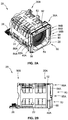
- FIGs. 2A and 2B show an individual fan module 20.
- FIG. 2A shows a perspective view of the fan module 20, and
- FIG. 2B shows a side elevation view of the fan module 20.
- the fan module 20 generally includes a housing 22 that defines a hollow interior 24 ( FIGs. 3A and 3B ).
- An individual fan (not shown) is positioned within the hollow interior 24 of the housing 22.
- a fan shield 26 is coupled to a first end 30A of the housing 22.
- the fan shield 26 protects the fan mounted within the housing 22, and prevents users (or other foreign objects) from inadvertently contacting the fan during use.
- a fan connector 28 can be coupled to an opposing second end 30B of the housing 22.
- the fan connector 28 electronically connects the fan to other components within the computing device or system. These other components can be used to control the fan during operation of the computing device or system.
- the fan module 20 further includes a first locking body 40A that is used to lock the fan module 20 to the chassis 12 or to the floor 16 of the chassis 12 ( FIG. 1 ).
- the fan module also has a second locking body that is shown in FIGs. 3A and 3B .
- a lever 80 is coupled to the housing 22. The lever 80 is used to move the first locking body 40A between a locked position and an unlocked position. When the first locking body 40A is moved to the unlocked position, the fan module 20 can be removed from the chassis 12.
- the fan module 20 further includes a frame piece 50 that is coupled to the housing 22.
- the frame piece 50 is coupled directly to the housing 22.
- the first locking body 40A is positioned between the housing 22 and the frame piece 50, and the lever 80 is pivotably mounted to the frame piece 50.
- the lever 80 can be pivoted between a first position (shown in FIGs. 2A, 2B , and 7A ) and a second position (shown in FIG. 9A ) in order to raise the first locking body 40A from the locked position (shown in FIGs. 2A, 2B , 7A, and 7B ) to the unlocked position (shown in FIGs. 9A and 9B ).
- the frame piece 50 is formed from a top support 52, a bottom support 54, a first side support 56, and a second side support 58.
- the first side support 56 connects one end of the top support 52 and the bottom support 54.
- the second side support 58 connects the opposite end of the top support 52 and the bottom support 54.
- the frame piece 50 has a generally square cross-section.
- the first end 30A of the housing 22 also has a generally square cross-section.
- the frame piece 50 and the housing 22 may have other types or shapes of cross-sections.
- the lever 80 is formed from a handle 82 connected to a first arm 84A and a second arm 84B.
- a proximal end 85A of the first arm 84A is coupled to the first side support 56 of the frame piece 50.
- a proximal end 85B of the second arm 84B is coupled to the second side support 58 of the frame piece 50.
- a distal end 86A of the first arm 84A is connected to one end of the handle 82.
- a distal end 86B of the second arm 84B is connected to the other end of the handle 82.
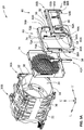
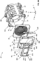
- FIGS. 3A and 3B show exploded views of the fan module 20 of FIGs. 2A and 2B .
- the exploded components include the fan shield 26; the locking bodies 40A and 40B; the frame piece 50 (formed from the top support 52, the bottom support 54, the first side support 56, and the second side support 58); and the lever 80.
- FIGs. 3A and 3B define three axes that are used herein to describe the various components of the fan module 20.
- the longitudinal axis L is the axis upon which the housing 22, the fan shield 26, the locking bodies 40A, 40B, the frame piece 50, and the lever 80 are all aligned.
- the fan is inserted into and removed from the housing 22 along the longitudinal axis L.
- the fan module 20 can be inserted into and removed from the chassis 12 along the longitudinal axis L.
- a vertical axis V is generally perpendicular to the longitudinal axis L.
- the vertical axis V connects a top edge 32 and a bottom edge 34 of the first end 30A of the housing 22.
- a transverse axis T is generally perpendicular to both the longitudinal axis L and the vertical axis T.
- the transverse axis T generally connects a first side edge 36 and a second side edge 38 of the first end 30A of the housing 22.
- the top support 52 forms a longitudinally-facing surface 74 that faces away from the housing 22.
- the upper portion of the first side support 56 of the frame piece 50 forms a first upper surface 70A that faces perpendicular to the longitudinally-facing surface 74.
- the upper portion of the second side support 58 forms a second upper surface 70B that also faces perpendicular to the longitudinally-facing surface 74.
- a first retention tab 72A extends upward from the first upper surface 70A, while a second retention tab 72B extends upward from the second upper surface
- the fan module 20 includes a first locking body 40A and a second locking body 40B that are positioned on either side of the housing 22.
- the first locking body 40A is positioned between the first side edge 36 of the housing 22, and the first side support 56 of the frame piece 50.
- the second locking body 40B is positioned between the second side edge 38 of the housing 22, and the second side support 58 of the frame piece 50.
- the first locking body 40A will generally be held in place by the first side edge 36 of the housing 22, and the first side support 56 of the frame piece 50.
- the second locking body 40B will generally be held in place by the second side edge 38 of the housing 22, and the second side support 58 of the frame piece 50.
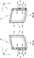
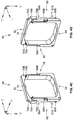
- FIGs. 4A and 4B show perspective views of a side of the frame piece 50 that faces toward the housing 22 ( FIGs. 3A and 3B ).
- FIGs. 4C and 4D show a perspective view of the opposite side of the frame piece 50 that faces away from the housing 22 ( FIGs. 3A and 3B ).
- the first side support 56 of the frame piece 50 includes a first outwardly-extending lip 60A, and a second outwardly-extending lip 76A.
- the outwardly-extending lips 60A and 76A extend along the transverse axis T in a first transverse direction, away from both the first side support 56 and the second side support 58.
- the second side support 58 similarly includes a first outwardly-extending lip 60B and a second outwardly extending lip 76B.
- the outwardly-extending lips 60B and 76B extend along the transverse axis T in a second transverse direction, away from both the first side support 56 and the second side support 58.
- the second transverse direction is generally parallel to and opposed to the first transverse direction.
- the first side support 56 of the frame piece 50 has a lower portion 57A and an upper portion 59A.
- the lower portion 57A is generally wider along the transverse axis T than the upper portion 59A.
- the lower portion 57A thus forms a longitudinally-facing surface 64A, and a transversely-facing surface 66A, that face perpendicular to each other.
- the second side support 58 of the frame piece 50 has a lower portion 57B and an upper portion 59B.
- the lower portion 57B is wider along the transverse axis T than the upper portion 59B.
- the lower portion 57B thus forms a longitudinally-facing surface 64B, and a transversely-facing surface 66B, that face perpendicular to each other.
- the first and second side supports 56, 58 have mounting bosses that aid in pivotably mounting the lever 80 to the frame piece 50.
- a first mounting boss 68A extends outward from the first side support 56 in the first transverse direction.
- a second mounting boss 68B extends outward from the second side support 58 in the second transverse direction.
- the longitudinal dimension of the top support 52 is generally smaller than the longitudinal dimension of the upper portion 59A of the first side support 56.
- the upper portion 59A thus forms the first upper surface 70A.
- the longitudinal dimension of the top support 52 is generally smaller than the longitudinal dimension of the upper portion 59B of the second side support 58.
- the upper portion 59B thus forms the second upper surface 70B.
- a first retention tab 72A extends upward along the vertical axis V from the first upper surface 70A.
- a second retention tab 72B extends upward along the vertical axis V from the second upper surface 70B.
- the top support 52 extends along the vertical axis V above the upper surfaces 70A, 70B of the first and second side supports 56, 58. The top support 52 thus forms a longitudinally-facing or lateral surface 74 that is generally perpendicular to the first and second upper surfaces 70A, 70B.
- FIGs. 5A and 5B show perspective view of the locking body 40A and the locking body 40B.
- the locking bodies 40A, 40B have a top portion 41A, a bottom portion 41B, and a thicker middle portion 41C.
- the top and bottom portions 41A, 41B are offset from their respective middle portions 41C in opposing directions.
- the bottom portion 41B of each locking body 40A, 40B is offset from the middle portion 41C in a direction away from the frame piece 50 ( FIGs. 3A and 3B ).
- the top portion 41A of each locking body 40A, 40B is offset from the middle portion 41C in a direction towards the frame piece 50.
- the bottom portion 41B of the first locking body 40A is offset from the middle portion 41C in the first transverse direction along the transverse axis T.
- the top portion 41A of first locking body 40A is offset from the middle portion 41C in the second transverse direction along the transverse axis T.
- the bottom portion 41B of the second locking body 40B is offset from the middle portion 41C in the second transverse direction along the transverse axis T.
- the top portion 41A of the second locking body 40B is offset from the middle portion 41C in the first transverse direction along the transverse axis T.
- the bottom portion 41B and the middle portion 41C of first locking body 40A forms an inwardly-extending (e.g., towards the frame piece 50) lip 42.
- the bottom portion 41B and the middle portion 41C of the second locking body 40B also form an inwardly-extending lip 42.
- the inwardly-extending lip 42 of the first locking body 40A rests on the outwardly-extending lip 60A of the first side support 56.
- the inwardly-extending lip 42 of the second locking body 40B rests on the outwardly-extending lip 60B of the second side support 58.
- Both of the locking bodies 40A, 40B also have an outwardly-extending lip 46.
- the outwardly-extending lip 46 extends from the top portions 41A of the locking bodies 40A, 40B along the transverse axis T, away from the frame piece 50.
- a curved tip 94A of the first arm 84A of the lever 80 contacts the outwardly-extending lip 46 of the first locking body 40A to move the first locking body 40A from the locked position to the unlocked position (shown in FIG. 6 ).
- a curved tip 94B of the second arm 84B of the lever 80 contacts the outwardly-extending lip 46 of the second locking body 40B to move the second locking body 40B from the locked position to the unlocked position.
- the first locking body 40A is positioned between (i) the first side edge 36 of the first end 30A of the housing 22, (ii) the longitudinally-facing surface 64A of the first side support 56, (iii) the transversely-facing surface 66A of the first side support 56, and (iv) the outwardly-extending lip 60A of the first side support 56.
- the second locking body 40B is positioned between (i) the second side edge 38 of first end 30A of the housing 22, (ii) the longitudinally-facing surface 64B of the second side support 58, (iii) the transversely-facing surface 66B of the second side support 58, and (iv) the outwardly-extending lip 60B of the second side support 58.
- the locking body 40A contacts the second outwardly-extending lip 76A when the locking body 40A is raised to the unlocked position.
- the locking body 40B contacts the second outwardly-extending lip 76B when the locking body 40B is raised to the unlocked position.
- the outwardly-extending lips 76A, 76B can prevent the lever 80 from being pivoted too far past the second position (shown in FIG. 9A ).
- the proximal end 85A of the first arm 84A has a corresponding first mounting aperture 88A.
- the proximal end 85B of the second arm 84B has a corresponding second mounting aperture 88B.
- the lever 80 is mounted to the frame piece 50, the proximal end 85A of the first arm 84A is placed over the first side support 56, so that the first mounting boss 68A extends through the first mounting aperture 88A.
- the proximal end 85B of the second arm 84B is placed over the second side support 58, so that the second mounting boss 68B extends through the second mounting aperture 88B.
- the first and second arms 84A, 84B of the lever 80 are thus pivotably mounted to the first and second side supports 56, 58, respectively, using the first and second mounting bosses 68A, 68B.
- the first mounting boss 68A is coupled to the proximal end 85A of the first arm 84A with an interference fit.
- the second mounting boss 68B can be coupled to the proximal end 85B of the second arm 84B with an interference fit.
- friction between the first mounting boss 68A and the periphery of the mounting aperture 88A secures the first arm 84A to the frame piece 50.
- friction between the second mounting boss 68B and the periphery of the mounting aperture 88B secures the second arm 84B to the frame piece 50.
- the friction between these components is large enough to prevent the first and second arms 84A, 84B from inadvertently slipping off of their respective mounting bosses 68A, 68B.
- the friction between these components is also small enough to allow the arms 84A, 84B (and thus the lever 80) to pivot with respect to the frame piece 50.
- the outer ends of the mounting bosses 68A, 68B have a diameter that is slightly larger than a diameter of the mounting apertures 88A, 88B.
- the remaining portions of the mounting bosses 68A, 68B have a diameter that is slightly less than the diameter of the mounting apertures 88A, 88B.
- the mounting bosses 68A, 68B are formed from a generally compressible material.
- the proximal ends 85A, 85B of the first and second arms 84A, 84B can be snapped over the mounting bosses 68A, 68B to secure the lever 80 to the frame piece 50.
- the force applied to the outer ends of the mounting bosses 68A, 68B causes the outer ends to compress slightly.
- the outer ends of the mounting bosses 68A, 68B can thus pass through the mounting apertures 88A, 88B.
- the larger diameter of the outer ends of the mounting bosses 68A, 68B then secures the first and second arms 84A, 84B to the frame piece 50.
- the first and second arms 84A, 84B extend upward along the vertical axis V and are generally parallel to the first and second side supports 56, 58 of the frame piece 50.
- the handle 82 of the lever 80 is positioned adjacent to and in close proximity with the longitudinally-facing surface 74 of the top support 52, and to the first and second upper surfaces 70A, 70B of the first and second side supports 56, 58.
- the lever 80 includes a latch 90 that is used to passively maintain the lever 80 in the first position.
- the latch 90 is coupled to an underside of the handle 82 via springs 92A, 92B.
- the springs 92A, 92B bias the latch 90 downward towards a resting position.
- a user can compress the springs 92A, 92B by squeezing the latch 90 and the handle 82.
- the latch 90 is thus caused to move upwards along the vertical axis V to a compressed position.
- the lever 80 When the fan module 20 is locked to the chassis 12, the lever 80 is in the first position adjacent to the top support 52 of the frame piece 50, and the latch 90 is in the resting position.
- the latch 90 When the latch 90 is in the resting position, the latch 90 is positioned adjacent to the first and second upper surfaces 70A, 70B of the first and second side supports 56, 58.
- the portion of the latch 90 near the first arm 84A is positioned between (i) the portion of the longitudinally-facing surface 74 of the top support 52 that is near the first side support 56, and (ii) the first retention tab 72A.
- the portion of the latch 90 near the second arm 84B is positioned between (i) the portion of the longitudinally-facing surface 74 of the top support 52 that is near the second side support 58, and (ii) the second retention tab 72B.
- the latch 90 is thus locked into place by (i) the longitudinally-facing surface 74 of the top support 52 and (ii) the first retention tab 72A and the second retention tab 72B. Because the latch 90 is coupled to the handle 82 of the lever 80, the lever 80 is also locked into place, and cannot be moved away from the first position toward the second position (shown in FIG. 9A ). The latch 90 thus prevents the fan module 20 from being inadvertently unlocked from the chassis 12 during use.
- the latch 90 is not positioned entirely between the retentions tabs 72A, 72B and the longitudinally-facing surface 74. Rather, the underside of the latch 90 may have apertures (not shown) into which the retention tabs 72A, 72B fit into when the lever is in the first position and the latch 90 is uncompressed. Thus, a portion of the latch 90 will be positioned on one side of the retentions tabs 72A, 72B (directly adjacent to the longitudinally-facing surface 74). Another portion of the latch 90 is positioned on the opposite side of the retention tabs 72A, 72B, opposite the longitudinally-facing surface 74.
- the latch 90 and the handle 82 are squeezed so that the springs 92A, 92B compress, moving the latch 90 to a compressed position.
- the latch 90 In the compressed position, the latch 90 is positioned above the first retention tab 72A and the second retention tab 72B, along the vertical axis V.
- the latch 90 is thus no longer locked into place between (i) the longitudinally-facing surface 74 of the top support 52 and (ii) the first retention tab 72A and the second retention tab 72B.
- the lever 80 is no longer prevented from pivoting from the first position to the second position.
- the first and second arms 84A, 84B In the second position, the first and second arms 84A, 84B extend along the longitudinal axis L and are generally perpendicular to the first and second side supports 56, 58.
- the handle 82 of the lever 80 is positioned away from the frame piece 50 along the longitudinal axis L.
- the latch 90 is generally the same length as the top support 52 and/or the handle 82.
- the latch 90 thus spans the entire transverse distance between (i) the first upper surface 70A of the first side support 56, and (ii) the second upper surface 70B of the second side support 58.
- the frame piece 50 has only one of the retention tabs 72A, 72B.
- the latch 90 thus does not need to be the same length as the top support 52 and/or the handle 82. Instead, the latch 90 can be located underneath the handle 82 near only one of the first arm 84A and the second arm 84B.
- the latch 90 When in the compressed position, the latch 90 is positioned between the longitudinally-facing surface 74 of the top support 52 and either the first retention tab 72A or the second retention tab 72B. In other implementations, the retention tab is positioned generally near the center of the top support 52, and the latch 90 is positioned generally near the center of the handle 82. The latch 90 can also be the same length as the handle 82, regardless of where the retention tabs are located.
- the longitudinal dimensions of both the top support 52 and the handle 82 are generally less than the longitudinal dimension of the upper portion 59A of the first side support 56, and the longitudinal dimension of the upper portion 59B of the second side support 58.
- the lever 80 can thus be positioned in close proximity to the top support 52 when the lever 80 is in the first position.
- the lever 80 does not extend along the longitudinal axis any further than the frame piece 50 itself, thus reducing the amount of space that the locking components of the fan module 20 occupy.
- the locking components of the fan module 20 extend beyond the first end 30A of the housing 22 a maximum distance of about 20.0 mm, about 19.0 mm, between about 19.0 mm and about 20.00 mm, or between about 15.0 mm and about 20.0 mm.
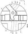
- FIG. 6 shows the interaction between (i) the proximal end 85A of the first arm 84A of the lever 80 and (ii) the first locking body 40A as the lever 80 is moved from the first position to the second position. While FIG. 4 shows only the first arm 84A and the first locking body 40A, the interaction between the proximal end 85B of the second arm 84B and the second locking body 40B ( FIGs. 3A and 3B ) is generally the same.
- the proximal end 85A of the first arm 84A terminates in the generally curved tip 94A.
- the curved tip 94A contacts the underside of the outwardly-extending lip 46 of the first locking body 40A.
- the lever 80 is pivoted from the first position to the second position, the proximal end 85A of the first arm 84A pivots about the first mounting boss 68A.
- the curved tip 94A moves upward along the vertical axis V, and away from the housing 22 along the longitudinal axis L.
- the curved tip 94A moves upwardly and outwardly, it pushes upward against the outwardly-extending lip 46 of the first locking body 40A.
- the curved tip 94A thus lifts the first locking body 40A along the vertical axis V, and moves the first locking body 40A from the locked position to the unlocked position.
- the curved tip 94A of the proximal end 85A of the first arm 84A thus acts as a cam that converts the pivoting movement of the lever 80 to linear movement of the first locking body 40A.
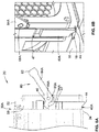
- FIGs. 7A-9B show the position of the lever 80 and the first locking body 40A relative to the housing 22 as the lever 80 moves from the first position to the second position, and thus as the locking body 40A moves from the locked position to the unlocked position. Similar to FIG. 6 , FIGs.7A-9B only show the first locking body 40A and the first arm 84A of the lever 80. However, the description of these components generally applies to the second locking body 40B and the second arm 84B ( FIGs. 3A and 3B ) of the lever 80 as well.
- the lever 80 is in the first position.
- the handle 82 is positioned adjacent to the top support 52 of the frame piece 50.
- the handle 82 is also positioned adjacent to (i) the upper surfaces 70A, 70B of the first and second side supports 56, 58 ( FIGs. 2A and 2B ), and (ii) the first and second retention tabs 72A, 72B ( FIGs. 3A and 3B ).
- the curved tip 94A points generally downward away from the outwardly-extending lip 46 of the first locking body 40A. The curved tip 94A thus does not contact the outwardly-extending lip 46, and the first locking body 40A is in the locked position.
- a bottom end 44 of the locking body 40A is positioned below the bottom edge 34 of the first end 30A housing 22. In the locked position, the bottom end 44 of the locking body 40A is also positioned below any other component or portion of the fan module 20 as well.
- the bottom end 44 of the locking body 40A extends through a locking aperture 18 defined in the floor 16 of the chassis 12, as shown in FIG. 7B . The fan module 20 is thus locked into place and prevented the fan module 20 from inadvertently moving within the chassis 12.
- the lever 80 has pivoted away from the first position into an intermediate position between the first position and the second position.
- the first arm 84A of the lever 80 is not parallel with the first side support 56, nor is the first arm 84A of the lever 80 perpendicular to the first side support 56.
- the curved tip 94A of the proximal end 85A of the first arm 84A has begun to pivot upwards.
- the curved tip 94A begins to contact the outwardly-extending lip 46 of the first locking body 40A.
- the curved tip 94A thus has begun to move the locking body 40A from the locked position. As shown in FIG.
- the lever 80 has pivoted all the way to the second position.
- the first arm 84A of the lever 80 is generally perpendicular to the first side support 56.
- the distal end 86A of the first arm 84A and the handle 82 are positioned away from the frame piece 50 along the longitudinal axis.
- the curved tip 94A of the proximal end 85A of the first arm 84A continues to pivot upwards.
- the first locking body 40A is raised to the unlocked position. As shown in FIG.
- FIG. 9A shows that the bottom end 44 of the first locking body 40A is positioned above the bottom edge 34 of the housing 22.
- FIG. 9B shows that when the fan module 20 is mounted in the chassis 12 and the first locking body 40A is moved to the unlocked position, the bottom end 44 of the first locking body 40A does not extend into the locking aperture 18 of the floor 16 of the chassis 12.
- the lever 80 moves to the second position to cause the locking body 40A to move to the unlocked position, the fan module 20 can safely be removed from the chassis 12.
- the amount that the first locking body 40A is moves upwards depends on the dimension of the first arm 84A between the first mounting aperture 88A and the outwardly-extending lip 46 of the first locking body 40A. Because the curved tip 94A of the first arm 84A curves down and away from the mounting aperture 88A, this dimension slowly increases as the lever 80 is pivoted to the second position and the curved tip 94A pivots upward. In FIG. 7A , the dimension of the first arm 84A between the first mounting aperture 88A and the outwardly-extending lip 46 of the first locking body 40A is minimized. The locking body 40A is thus settled into the locked position.
- the curved tip 94A has begun to pivot upwards.
- the dimension of the first arm 84A between the first mounting aperture 88A and the outwardly-extending lip 46 of the first locking body 40A has increased due to the curve of the tip.
- the locking body 40A is initially raised from the locked position.
- the dimension of the first arm 84A between the first mounting aperture 88A and the outwardly-extending lip 46 of the first locking body 40A is at a maximum.
- the lever 80 has pivoted all the way to the second position, and thus the curved tip 94A has pivoted upwards enough that it is generally positioned between the first mounting aperture 88A and the outwardly-extending lip 46 of the first locking body 40A.
- the curved tip 94A has thus caused the locking body 40A to be completely raised to the unlocked position.
- the point of contact between the proximal end 85A of the first arm 84A and the outwardly-extending lip 46 of the first locking body 40A moves upward in a generally vertical direction as the lever 80 moves from the first position to the second position.
- the first and second locking bodies 40A, 40B may be biased towards the locked position.
- one or more springs are positioned so as to compress as the first and second locking bodies 40A, 40B are moved upward to the locked position.
- the springs expand once the force moving the lever 80 to the second position is removed, automatically returning the first and second locking bodies 40A, 40B to their locked position.
- the first and second locking bodies 40A, 40B are made of a material that is generally compressible. As the first and second locking bodies 40A, 40B are moved to the unlocked position, they each compress as they are pressed against the outwardly-extending lips 76A, 76B of the first and second side supports 56, 58. Then, once the force moving the lever 80 to the second position is removed, the first and second locking bodies 40A, 40B expand and begin return to their unlocked positions.
- the locking bodies 40A, 40B remain in the unlocked position once they are moved upward.
- the lever 80 is moved back to the first position.
- the curved tips 94A, 94B can contact a second outwardly-extending lip 47 ( FIGs. 5A and 5B ) of the locking bodies 40A, 40B to force the locking bodies 40A, 40B back to the locked position.
- the lever 80 can mean both directly coupled or indirectly coupled.
- the lever 80 is coupled to the housing 22 by mounting the lever 80 to the frame piece 50, and attaching the frame piece 50 to the housing 22 and/or the fan shield 26.
- the lever 80 is coupled to the housing 22 by pivotally mounting the lever 80 directly to the housing 22.
- the housing 22 can be shaped to include various features from the frame piece 50, such as the outwardly-extending lips 60A, 60B and the mounting bosses 68A, 68B.
Landscapes
- Engineering & Computer Science (AREA)
- General Engineering & Computer Science (AREA)
- Theoretical Computer Science (AREA)
- Mechanical Engineering (AREA)
- Physics & Mathematics (AREA)
- Microelectronics & Electronic Packaging (AREA)
- Human Computer Interaction (AREA)
- General Physics & Mathematics (AREA)
- Thermal Sciences (AREA)
- Computer Hardware Design (AREA)
- Power Engineering (AREA)
- Cooling Or The Like Of Electrical Apparatus (AREA)
- Structures Of Non-Positive Displacement Pumps (AREA)
Abstract
Description
- The present disclosure relates generally to a fan module for cooling a computing device or system. More particularly, aspects of this disclosure relate to a fan module with a lever that is used to lock the fan module to the chassis and unlock the fan module from the chassis.
- Fans modules are used computing devices and systems to cool the device or system during use. Generally, one or more fan modules will be mounted in a chassis during use to stabilize the fan modules and provide strict placement within the computing device or system. The fan modules need to be locked into place within the chassis to prevent inadvertent movement during use. However, the fan modules must also be able to be easily removed from the chassis to be repaired or replaced. Components that allow the fan modules to be locked into place within the chassis, but also allow the fan modules to be easily unlocked for repair or replacement, are often bulky or unwieldy. However, utilizing space efficiently within the computing device or system is important, and these bulky or unwieldy components are often impractical.
- Thus, there is a need for an improved fan module that can be locked to and unlocked from a chassis easily, while occupying a minimal amount of space.
- The various examples of the present disclosure are directed towards a fan module. In a first embodiment of the present disclosure, the fan module comprises a housing, a locking body, and a lever. The housing defines a hollow interior configured to house a fan. The locking body is coupled to the housing and is moveable between a locked position and an unlocked position. The lever is coupled to the housing and is moveable between a first position and a second position. Moving the lever from the first position to the second position causes the locking body to move from the locked position to the unlocked position.
- In some examples of the first embodiment, the bottom end of the locking body is positioned below a lower edge of the housing when the locking body is in the locked position.
- In some examples of the first embodiment, the bottom end of the locking body is positioned above a lower edge of the housing when the locking body is in the unlocked position.
- In some examples of the first embodiment, the lever includes a proximal end and a distal end. The proximal end of the lever is pivotably coupled to the housing.
- In some examples of the first embodiment, the proximal end of the lever contacts the locking body and moves the locking body from the locked position to the unlocked position as the lever moves from the first position to the second position.
- In some examples of the first embodiment, the proximal lend of the lever has a curved tip, and the locking body has an outwardly-extending lip. The outwardly-extending lip of the locking body is configured to contact the curved tip of the proximal end of the lever.
- In some examples of the first embodiment, the curved tip of the proximal end of the lever pivots as the lever pivots from the first position to the second position. When the curved tip pivots, the curved tip raises the outwardly-extending lip of the locking body such that the locking body moves from the locked position to the unlocked position.
- In some examples of the first embodiment, the point of contact between (i) the curved tip of the proximal end of the lever and (ii) the outwardly-extending lip of the locking body moves upward in a generally vertical direction as the lever moves from the first position to the second position
- In some examples of the first embodiment, the locking body is biased toward the locked position.
- In some examples of the first embodiment, the locking body is biased using (i) one or more springs, (ii) a flexible or compressible portion of the locking body, or (iii) both (i) and (ii).
- In some examples of the first embodiment, the fan module further comprises a frame piece coupled to an end of the housing. The frame piece includes a top support, a first side support coupled to a first end of the top support, and a second side support coupled to a second end of the top support. The lever is pivotably mounted to the frame piece.
- In some examples of the first embodiment, the lever includes a first arm, a second arm, and a handle. A proximal end of the first arm is pivotably mounted to the first side support of the frame piece. A proximal end of the second arm is pivotably mounted to the second side support of the frame piece. The handle is coupled to a distal end of the first arm and a distal end of the second arm.
- In some examples of the first embodiment, the frame piece includes at least one upper surface formed by (i) a top end of the first side support, (ii) a top end of the second side support, or (iii) both (i) and (ii). The frame piece also includes a lateral surface formed by the top support. The lateral surface being positioned generally perpendicular to the at least one upper surface.
- In some examples of the first embodiment, when the lever is in the first position, the handle of the lever is adjacent to (i) the at least one upper surface and (ii) the lateral surface. In the first position, the first arm and the second arm are generally parallel to the first side support and the second side support. When the lever is in the second position, the handle of the lever extends outward from the frame piece. In the second position, the first arm and the second arm are generally perpendicular to the first side support and the second side.
- In some examples of the first embodiment, the lever further comprises a latch coupled to the handle. The latch is moveable between a resting position and a compressed position, the latch is biased toward the resting position.
- In some examples of the first embodiment, the frame piece includes one or more tabs projecting from the at least one upper surface of the frame piece. The latch of the lever is positioned between the lateral surface of the frame piece and the one or more tabs when the lever is in the first position and the latch is in the resting position. In this configuration, the lever is prevented from moving from the first position to the second position.
- In some examples of the first embodiment, moving the latch from the resting position to the compressed position raises the latch above the one or more tabs. In this configuration, the lever is not prevented from moving from the first position to the second position.
- In some examples of the first embodiment, the first side support includes an outwardly-extending lip, and the locking body includes an inwardly-extending lip. The inwardly-extending lip of the locking body resting upon the outwardly-extending lip of the first side support when the lever is in the first position.
- In some examples of the first embodiment, moving the lever from the first position to the second position causes the lever to contact the locking body. The contact between the lever and the locking body causes the inwardly-extending lip of the locking body to be raised off of the outwardly-extending lip of the first side support.
- In some examples of the first embodiment, the fan module is present in combination with a chassis. The chassis is configured to hold one or more fan modules. The fan module is mounted on a floor of the chassis. When the locking body is in the locked position, the locking body extends through a locking aperture defined in the floor of the chassis. Moving the lever from the first position to the second position raises the locking body out of the locking aperture to the unlocked position.
- The above summary is not intended to represent each embodiment or every aspect of the present disclosure. Rather, the foregoing summary merely provides an example of some of the novel aspects and features set forth herein. The above features and advantages, and other features and advantages of the present disclosure, will be readily apparent from the following detailed description of representative embodiments and modes for carrying out the present invention, when taken in connection with the accompanying drawings and the appended claims.
- The disclosure will be better understood from the following description of exemplary embodiments together with reference to the accompanying drawings, in which:
-
FIG. 1 is a fan wall including a plurality of fan modules mounted within a chassis; -
FIG. 2A is a perspective view of one of the fan modules ofFIG. 1 ; -
FIG. 2B is a side elevation view of the fan module ofFIG. 2A ; -
FIG. 3A is a first exploded perspective view of the fan module ofFIGs. 2A and 2B ; -
FIG. 3B is a second exploded perspective view of the fan module ofFIGs. 2A and 2B ; -
FIG. 4A is a first perspective view of a first side of a frame piece of the fan module ofFIGs. 2A and 2B ; -
FIG. 4B is a second perspective view of the first side of the frame piece ofFIG. 4A ; -
FIG. 4C is a first perspective view of a second side of the frame piece ofFIG. 4A ; -
FIG. 4D is a second perspective view of the second side of the frame piece ofFIG. 4A ; -
FIG. 5A is a first perspective view of a pair of locking bodies of the fan module ofFIGs. 2A and 2B ; -
FIG. 5B is a second perspective view of the pair of locking bodies ofFIG. 5A ; -
FIG. 6 is a zoomed-in view of a lever and a locking body of the fan module ofFIGs. 2A and 2B ; -
FIG. 7A is a side elevation view of the fan module ofFIGs. 2A and 2B when the lever is in a first position; -
FIG. 7B is a zoomed-in perspective view of the locking body of the fan module ofFIGs. 2A and 2B when the lever is in the first position; -
FIG. 8A is a side elevation view of the fan module ofFIGs. 2A and 2B when the lever is between the first position and a second position; -
FIG. 8B is a zoomed-in perspective view of the locking body of the fan module ofFIGs. 2A and 2B when the lever is between the first position and the second position; -
FIG. 9A is a side elevation view of the fan module ofFIGs. 2A and 2B when the lever is in the second position; and -
FIG. 9B is a zoomed-in perspective view of the locking body of the fan module ofFIGs. 2A and 2B when the lever is in the second position. - The present disclosure is susceptible to various modifications and alternative forms. Some representative embodiments have been shown by way of example in the drawings and will be described in detail herein. It should be understood, however, that the invention is not intended to be limited to the particular forms disclosed. Rather, the disclosure is to cover all modifications, equivalents, and alternatives falling within the spirit and scope of the invention as defined by the appended claims.
- The present inventions can be embodied in many different forms. Representative embodiments are shown in the drawings, and will herein be described in detail. The present disclosure is an example or illustration of the principles of the present disclosure, and is not intended to limit the broad aspects of the disclosure to the embodiments illustrated. To that extent, elements, and limitations that are disclosed, for example, in the Abstract, Summary, and Detailed Description sections, but not explicitly set forth in the claims, should not be incorporated into the claims, singly or collectively, by implication, inference, or otherwise. For purposes of the present detailed description, unless specifically disclaimed, the singular includes the plural and vice versa; and the word "including" means "including without limitation." Moreover, words of approximation, such as "about," "almost," "substantially," "approximately," and the like, can be used herein to mean "at," "near," or "nearly at," or "within 3-5% of," or "within acceptable manufacturing tolerances," or any logical combination thereof, for example.
-
FIG. 1 shows afan wall 10 that includes a number offan modules 20. Thefan modules 20 are mounted within achassis 12. Eachfan module 20 is mounted within arespective socket 14 in thechassis 12. Thefan modules 20 rest on thefloor 16 of theirrespective sockets 14. Eachfan module 20 contains at least one fan (not shown). Thefan modules 20 mounted in thechassis 12 can be included as part of a computing device or system, such as a server. The components of the computing device or system are cooled by the fans during operation of the computing device or system. As is discussed in more detail below, thefan modules 20 can be locked to thechassis 12 to prevent unwanted movement during use. -
FIGs. 2A and 2B show anindividual fan module 20.FIG. 2A shows a perspective view of thefan module 20, andFIG. 2B shows a side elevation view of thefan module 20. Thefan module 20 generally includes ahousing 22 that defines a hollow interior 24 (FIGs. 3A and3B ). An individual fan (not shown) is positioned within thehollow interior 24 of thehousing 22. Afan shield 26 is coupled to afirst end 30A of thehousing 22. Thefan shield 26 protects the fan mounted within thehousing 22, and prevents users (or other foreign objects) from inadvertently contacting the fan during use. Afan connector 28 can be coupled to an opposingsecond end 30B of thehousing 22. Thefan connector 28 electronically connects the fan to other components within the computing device or system. These other components can be used to control the fan during operation of the computing device or system. - The
fan module 20 further includes afirst locking body 40A that is used to lock thefan module 20 to thechassis 12 or to thefloor 16 of the chassis 12 (FIG. 1 ). The fan module also has a second locking body that is shown inFIGs. 3A and3B . In order to repair or replace thefan module 20, alever 80 is coupled to thehousing 22. Thelever 80 is used to move thefirst locking body 40A between a locked position and an unlocked position. When thefirst locking body 40A is moved to the unlocked position, thefan module 20 can be removed from thechassis 12. - The
fan module 20 further includes aframe piece 50 that is coupled to thehousing 22. In the implementation illustrated inFIGs. 2A and 2B , theframe piece 50 is coupled directly to thehousing 22. Thefirst locking body 40A is positioned between thehousing 22 and theframe piece 50, and thelever 80 is pivotably mounted to theframe piece 50. As will be explained in more detail below, thelever 80 can be pivoted between a first position (shown inFIGs. 2A, 2B , and7A ) and a second position (shown inFIG. 9A ) in order to raise thefirst locking body 40A from the locked position (shown inFIGs. 2A, 2B ,7A, and 7B ) to the unlocked position (shown inFIGs. 9A and 9B ). - The
frame piece 50 is formed from atop support 52, abottom support 54, afirst side support 56, and asecond side support 58. Thefirst side support 56 connects one end of thetop support 52 and thebottom support 54. Similarly, thesecond side support 58 connects the opposite end of thetop support 52 and thebottom support 54. In the implementation illustrated inFIGs. 2A and 2B , theframe piece 50 has a generally square cross-section. Thefirst end 30A of thehousing 22 also has a generally square cross-section. In other implementations, theframe piece 50 and thehousing 22 may have other types or shapes of cross-sections. - The
lever 80 is formed from ahandle 82 connected to afirst arm 84A and asecond arm 84B. Aproximal end 85A of thefirst arm 84A is coupled to thefirst side support 56 of theframe piece 50. Aproximal end 85B of thesecond arm 84B is coupled to thesecond side support 58 of theframe piece 50. Adistal end 86A of thefirst arm 84A is connected to one end of thehandle 82. Adistal end 86B of thesecond arm 84B is connected to the other end of thehandle 82. -
FIGS. 3A and3B show exploded views of thefan module 20 ofFIGs. 2A and 2B . The exploded components include thefan shield 26; the lockingbodies top support 52, thebottom support 54, thefirst side support 56, and the second side support 58); and thelever 80.FIGs. 3A and3B define three axes that are used herein to describe the various components of thefan module 20. The longitudinal axis L is the axis upon which thehousing 22, thefan shield 26, the lockingbodies frame piece 50, and thelever 80 are all aligned. The fan is inserted into and removed from thehousing 22 along the longitudinal axis L. Thefan module 20 can be inserted into and removed from thechassis 12 along the longitudinal axis L. - A vertical axis V is generally perpendicular to the longitudinal axis L. The vertical axis V connects a
top edge 32 and abottom edge 34 of thefirst end 30A of thehousing 22. A transverse axis T is generally perpendicular to both the longitudinal axis L and the vertical axis T. The transverse axis T generally connects afirst side edge 36 and asecond side edge 38 of thefirst end 30A of thehousing 22. These axes L, V, and T are also shown inFIGs. 4A-5B . - As can be seen
FIGs. 3A and3B , thetop support 52 forms a longitudinally-facingsurface 74 that faces away from thehousing 22. The upper portion of thefirst side support 56 of theframe piece 50 forms a firstupper surface 70A that faces perpendicular to the longitudinally-facingsurface 74. The upper portion of thesecond side support 58 forms a secondupper surface 70B that also faces perpendicular to the longitudinally-facingsurface 74. Afirst retention tab 72A extends upward from the firstupper surface 70A, while asecond retention tab 72B extends upward from the second upper surface - As shown, the
fan module 20 includes afirst locking body 40A and asecond locking body 40B that are positioned on either side of thehousing 22. Thefirst locking body 40A is positioned between thefirst side edge 36 of thehousing 22, and thefirst side support 56 of theframe piece 50. Thesecond locking body 40B is positioned between thesecond side edge 38 of thehousing 22, and thesecond side support 58 of theframe piece 50. When thefan module 20 is assembled (shown inFIGs. 2A and 2B ), thefirst locking body 40A will generally be held in place by thefirst side edge 36 of thehousing 22, and thefirst side support 56 of theframe piece 50. Similarly, thesecond locking body 40B will generally be held in place by thesecond side edge 38 of thehousing 22, and thesecond side support 58 of theframe piece 50. -
FIGs. 4A and 4B show perspective views of a side of theframe piece 50 that faces toward the housing 22 (FIGs. 3A and3B ).FIGs. 4C and 4D show a perspective view of the opposite side of theframe piece 50 that faces away from the housing 22 (FIGs. 3A and3B ). Thefirst side support 56 of theframe piece 50 includes a first outwardly-extendinglip 60A, and a second outwardly-extendinglip 76A. The outwardly-extendinglips first side support 56 and thesecond side support 58. Thesecond side support 58 similarly includes a first outwardly-extendinglip 60B and a second outwardly extendinglip 76B. The outwardly-extendinglips first side support 56 and thesecond side support 58. The second transverse direction is generally parallel to and opposed to the first transverse direction. - The
first side support 56 of theframe piece 50 has alower portion 57A and anupper portion 59A. Thelower portion 57A is generally wider along the transverse axis T than theupper portion 59A. Thelower portion 57A thus forms a longitudinally-facingsurface 64A, and a transversely-facingsurface 66A, that face perpendicular to each other. Similarly, thesecond side support 58 of theframe piece 50 has alower portion 57B and anupper portion 59B. Thelower portion 57B is wider along the transverse axis T than theupper portion 59B. Thelower portion 57B thus forms a longitudinally-facingsurface 64B, and a transversely-facingsurface 66B, that face perpendicular to each other. - The first and second side supports 56, 58 have mounting bosses that aid in pivotably mounting the
lever 80 to theframe piece 50. A first mountingboss 68A extends outward from thefirst side support 56 in the first transverse direction. A second mountingboss 68B extends outward from thesecond side support 58 in the second transverse direction. - The longitudinal dimension of the
top support 52 is generally smaller than the longitudinal dimension of theupper portion 59A of thefirst side support 56. Theupper portion 59A thus forms the firstupper surface 70A. Similarly, the longitudinal dimension of thetop support 52 is generally smaller than the longitudinal dimension of theupper portion 59B of thesecond side support 58. Theupper portion 59B thus forms the secondupper surface 70B. - A
first retention tab 72A extends upward along the vertical axis V from the firstupper surface 70A. Asecond retention tab 72B extends upward along the vertical axis V from the secondupper surface 70B. Thetop support 52 extends along the vertical axis V above theupper surfaces top support 52 thus forms a longitudinally-facing orlateral surface 74 that is generally perpendicular to the first and secondupper surfaces -
FIGs. 5A and 5B show perspective view of the lockingbody 40A and the lockingbody 40B. The lockingbodies top portion 41A, abottom portion 41B, and a thickermiddle portion 41C. The top andbottom portions middle portions 41C in opposing directions. Thebottom portion 41B of each lockingbody middle portion 41C in a direction away from the frame piece 50 (FIGs. 3A and3B ). Thetop portion 41A of each lockingbody middle portion 41C in a direction towards theframe piece 50. - Thus, the
bottom portion 41B of thefirst locking body 40A is offset from themiddle portion 41C in the first transverse direction along the transverse axis T. Thetop portion 41A offirst locking body 40A is offset from themiddle portion 41C in the second transverse direction along the transverse axis T. Thebottom portion 41B of thesecond locking body 40B is offset from themiddle portion 41C in the second transverse direction along the transverse axis T. Thetop portion 41A of thesecond locking body 40B is offset from themiddle portion 41C in the first transverse direction along the transverse axis T. - The
bottom portion 41B and themiddle portion 41C offirst locking body 40A forms an inwardly-extending (e.g., towards the frame piece 50)lip 42. Thebottom portion 41B and themiddle portion 41C of thesecond locking body 40B also form an inwardly-extendinglip 42. When thefan module 20 is assembled, the inwardly-extendinglip 42 of thefirst locking body 40A rests on the outwardly-extendinglip 60A of thefirst side support 56. The inwardly-extendinglip 42 of thesecond locking body 40B rests on the outwardly-extendinglip 60B of thesecond side support 58. - Both of the locking
bodies lip 46. The outwardly-extendinglip 46 extends from thetop portions 41A of the lockingbodies frame piece 50. As is explained in more detail below, acurved tip 94A of thefirst arm 84A of thelever 80 contacts the outwardly-extendinglip 46 of thefirst locking body 40A to move thefirst locking body 40A from the locked position to the unlocked position (shown inFIG. 6 ). Similarly, acurved tip 94B of thesecond arm 84B of thelever 80 contacts the outwardly-extendinglip 46 of thesecond locking body 40B to move thesecond locking body 40B from the locked position to the unlocked position. - Referring to
FIGs. 4A-5B , when thefan module 20 is assembled (FIGs. 2A and 2B ), thefirst locking body 40A is positioned between (i) thefirst side edge 36 of thefirst end 30A of thehousing 22, (ii) the longitudinally-facingsurface 64A of thefirst side support 56, (iii) the transversely-facingsurface 66A of thefirst side support 56, and (iv) the outwardly-extendinglip 60A of thefirst side support 56. When thefan module 20 is assembled, thesecond locking body 40B is positioned between (i) thesecond side edge 38 offirst end 30A of thehousing 22, (ii) the longitudinally-facingsurface 64B of thesecond side support 58, (iii) the transversely-facingsurface 66B of thesecond side support 58, and (iv) the outwardly-extendinglip 60B of thesecond side support 58. - In some implementations, the locking
body 40A contacts the second outwardly-extendinglip 76A when the lockingbody 40A is raised to the unlocked position. Similarly, in some implementations, the lockingbody 40B contacts the second outwardly-extendinglip 76B when the lockingbody 40B is raised to the unlocked position. Thus, the outwardly-extendinglips lever 80 from being pivoted too far past the second position (shown inFIG. 9A ). - Referring back to
FIGs. 3A and3B , theproximal end 85A of thefirst arm 84A has a corresponding first mountingaperture 88A. Theproximal end 85B of thesecond arm 84B has a corresponding second mountingaperture 88B. When thelever 80 is mounted to theframe piece 50, theproximal end 85A of thefirst arm 84A is placed over thefirst side support 56, so that the first mountingboss 68A extends through the first mountingaperture 88A. Similarly, theproximal end 85B of thesecond arm 84B is placed over thesecond side support 58, so that the second mountingboss 68B extends through thesecond mounting aperture 88B. The first andsecond arms lever 80 are thus pivotably mounted to the first and second side supports 56, 58, respectively, using the first and second mountingbosses - In some implementations, the first mounting
boss 68A is coupled to theproximal end 85A of thefirst arm 84A with an interference fit. Similarly, the second mountingboss 68B can be coupled to theproximal end 85B of thesecond arm 84B with an interference fit. In these implementations, friction between the first mountingboss 68A and the periphery of the mountingaperture 88A secures thefirst arm 84A to theframe piece 50. Similarly, friction between the second mountingboss 68B and the periphery of the mountingaperture 88B secures thesecond arm 84B to theframe piece 50. The friction between these components is large enough to prevent the first andsecond arms respective mounting bosses arms frame piece 50. - In other implementations, the outer ends of the mounting
bosses apertures bosses apertures bosses second arms bosses lever 80 to theframe piece 50. The force applied to the outer ends of the mountingbosses bosses apertures bosses second arms frame piece 50. - When the
lever 80 is in the first position (shown inFIGs. 2A, 2B , and7A ), the first andsecond arms frame piece 50. In the first position, thehandle 82 of thelever 80 is positioned adjacent to and in close proximity with the longitudinally-facingsurface 74 of thetop support 52, and to the first and secondupper surfaces - The
lever 80 includes alatch 90 that is used to passively maintain thelever 80 in the first position. Thelatch 90 is coupled to an underside of thehandle 82 viasprings springs latch 90 downward towards a resting position. A user can compress thesprings latch 90 and thehandle 82. Thelatch 90 is thus caused to move upwards along the vertical axis V to a compressed position. - When the
fan module 20 is locked to thechassis 12, thelever 80 is in the first position adjacent to thetop support 52 of theframe piece 50, and thelatch 90 is in the resting position. When thelatch 90 is in the resting position, thelatch 90 is positioned adjacent to the first and secondupper surfaces latch 90 near thefirst arm 84A is positioned between (i) the portion of the longitudinally-facingsurface 74 of thetop support 52 that is near thefirst side support 56, and (ii) thefirst retention tab 72A. - Similarly, the portion of the
latch 90 near thesecond arm 84B is positioned between (i) the portion of the longitudinally-facingsurface 74 of thetop support 52 that is near thesecond side support 58, and (ii) thesecond retention tab 72B. Thelatch 90 is thus locked into place by (i) the longitudinally-facingsurface 74 of thetop support 52 and (ii) thefirst retention tab 72A and thesecond retention tab 72B. Because thelatch 90 is coupled to thehandle 82 of thelever 80, thelever 80 is also locked into place, and cannot be moved away from the first position toward the second position (shown inFIG. 9A ). Thelatch 90 thus prevents thefan module 20 from being inadvertently unlocked from thechassis 12 during use. - In other implementations, the
latch 90 is not positioned entirely between theretentions tabs surface 74. Rather, the underside of thelatch 90 may have apertures (not shown) into which theretention tabs latch 90 is uncompressed. Thus, a portion of thelatch 90 will be positioned on one side of theretentions tabs latch 90 is positioned on the opposite side of theretention tabs surface 74. - To unlock the
lever 80, thelatch 90 and thehandle 82 are squeezed so that thesprings latch 90 to a compressed position. In the compressed position, thelatch 90 is positioned above thefirst retention tab 72A and thesecond retention tab 72B, along the vertical axis V. Thelatch 90 is thus no longer locked into place between (i) the longitudinally-facingsurface 74 of thetop support 52 and (ii) thefirst retention tab 72A and thesecond retention tab 72B. Thelever 80 is no longer prevented from pivoting from the first position to the second position. In the second position, the first andsecond arms handle 82 of thelever 80 is positioned away from theframe piece 50 along the longitudinal axis L. - In the illustrated implementation, the
latch 90 is generally the same length as thetop support 52 and/or thehandle 82. Thelatch 90 thus spans the entire transverse distance between (i) the firstupper surface 70A of thefirst side support 56, and (ii) the secondupper surface 70B of thesecond side support 58. Other implementations are also possible however. In one implementation, theframe piece 50 has only one of theretention tabs latch 90 thus does not need to be the same length as thetop support 52 and/or thehandle 82. Instead, thelatch 90 can be located underneath thehandle 82 near only one of thefirst arm 84A and thesecond arm 84B. When in the compressed position, thelatch 90 is positioned between the longitudinally-facingsurface 74 of thetop support 52 and either thefirst retention tab 72A or thesecond retention tab 72B. In other implementations, the retention tab is positioned generally near the center of thetop support 52, and thelatch 90 is positioned generally near the center of thehandle 82. Thelatch 90 can also be the same length as thehandle 82, regardless of where the retention tabs are located. - The locking components of the fan module 20-the
frame piece 50; the first andsecond locking bodies lever 80; and the handle 82-occupy a small amount of space beyond thefirst end 30A of thehousing 22 when in use. The longitudinal dimensions of both thetop support 52 and thehandle 82 are generally less than the longitudinal dimension of theupper portion 59A of thefirst side support 56, and the longitudinal dimension of theupper portion 59B of thesecond side support 58. Thelever 80 can thus be positioned in close proximity to thetop support 52 when thelever 80 is in the first position. - The
lever 80 does not extend along the longitudinal axis any further than theframe piece 50 itself, thus reducing the amount of space that the locking components of thefan module 20 occupy. In some implementations, the locking components of thefan module 20 extend beyond thefirst end 30A of the housing 22 a maximum distance of about 20.0 mm, about 19.0 mm, between about 19.0 mm and about 20.00 mm, or between about 15.0 mm and about 20.0 mm. -
FIG. 6 shows the interaction between (i) theproximal end 85A of thefirst arm 84A of thelever 80 and (ii) thefirst locking body 40A as thelever 80 is moved from the first position to the second position. WhileFIG. 4 shows only thefirst arm 84A and thefirst locking body 40A, the interaction between theproximal end 85B of thesecond arm 84B and thesecond locking body 40B (FIGs. 3A and3B ) is generally the same. - As shown, the
proximal end 85A of thefirst arm 84A terminates in the generallycurved tip 94A. Thecurved tip 94A contacts the underside of the outwardly-extendinglip 46 of thefirst locking body 40A. As thelever 80 is pivoted from the first position to the second position, theproximal end 85A of thefirst arm 84A pivots about the first mountingboss 68A. Thecurved tip 94A moves upward along the vertical axis V, and away from thehousing 22 along the longitudinal axis L. - As the
curved tip 94A moves upwardly and outwardly, it pushes upward against the outwardly-extendinglip 46 of thefirst locking body 40A. Thecurved tip 94A thus lifts thefirst locking body 40A along the vertical axis V, and moves thefirst locking body 40A from the locked position to the unlocked position. Thecurved tip 94A of theproximal end 85A of thefirst arm 84A thus acts as a cam that converts the pivoting movement of thelever 80 to linear movement of thefirst locking body 40A. -
FIGs. 7A-9B show the position of thelever 80 and thefirst locking body 40A relative to thehousing 22 as thelever 80 moves from the first position to the second position, and thus as the lockingbody 40A moves from the locked position to the unlocked position. Similar toFIG. 6 ,FIGs.7A-9B only show thefirst locking body 40A and thefirst arm 84A of thelever 80. However, the description of these components generally applies to thesecond locking body 40B and thesecond arm 84B (FIGs. 3A and3B ) of thelever 80 as well. - In
FIGs. 7A and 7B , thelever 80 is in the first position. In the first position, thehandle 82 is positioned adjacent to thetop support 52 of theframe piece 50. Thehandle 82 is also positioned adjacent to (i) theupper surfaces FIGs. 2A and 2B ), and (ii) the first andsecond retention tabs FIGs. 3A and3B ). When thelever 80 is in the first position, thecurved tip 94A points generally downward away from the outwardly-extendinglip 46 of thefirst locking body 40A. Thecurved tip 94A thus does not contact the outwardly-extendinglip 46, and thefirst locking body 40A is in the locked position. - In the locked position, a
bottom end 44 of the lockingbody 40A is positioned below thebottom edge 34 of thefirst 22. In the locked position, theend 30A housingbottom end 44 of the lockingbody 40A is also positioned below any other component or portion of thefan module 20 as well. When thefan module 20 is resting on thefloor 16 of the chassis, thebottom end 44 of the lockingbody 40A extends through a lockingaperture 18 defined in thefloor 16 of thechassis 12, as shown inFIG. 7B . Thefan module 20 is thus locked into place and prevented thefan module 20 from inadvertently moving within thechassis 12. - In
FIGs. 8A and 8B , thelever 80 has pivoted away from the first position into an intermediate position between the first position and the second position. Here, thefirst arm 84A of thelever 80 is not parallel with thefirst side support 56, nor is thefirst arm 84A of thelever 80 perpendicular to thefirst side support 56. Because thelever 80 has begun to pivot away from the first position, thecurved tip 94A of theproximal end 85A of thefirst arm 84A has begun to pivot upwards. Thecurved tip 94A begins to contact the outwardly-extendinglip 46 of thefirst locking body 40A. Thecurved tip 94A thus has begun to move the lockingbody 40A from the locked position. As shown inFIG. 8A , thebottom end 44 of the lockingbody 40A has not yet risen above thebottom edge 34 of thehousing 22. As shown inFIG. 8B , when thelever 80 is moved to the intermediate position, thebottom end 44 of the lockingbody 40A has not yet risen out of the lockingaperture 18 defined in thefloor 16. - In
FIGs. 9A and 9B , thelever 80 has pivoted all the way to the second position. In the second position, thefirst arm 84A of thelever 80 is generally perpendicular to thefirst side support 56. Thedistal end 86A of thefirst arm 84A and thehandle 82 are positioned away from theframe piece 50 along the longitudinal axis. As thelever 80 pivots to the second position, thecurved tip 94A of theproximal end 85A of thefirst arm 84A continues to pivot upwards. As thecurved tip 94A presses against the outwardly-extendinglip 46 of thefirst locking body 40A, thefirst locking body 40A is raised to the unlocked position. As shown inFIG. 9A , thebottom end 44 of thefirst locking body 40A is positioned above thebottom edge 34 of thehousing 22.FIG. 9B shows that when thefan module 20 is mounted in thechassis 12 and thefirst locking body 40A is moved to the unlocked position, thebottom end 44 of thefirst locking body 40A does not extend into the lockingaperture 18 of thefloor 16 of thechassis 12. Thus, when thelever 80 moves to the second position to cause the lockingbody 40A to move to the unlocked position, thefan module 20 can safely be removed from thechassis 12. - As can be seen in
FIGs. 7A ,8A , and9A , the amount that thefirst locking body 40A is moves upwards depends on the dimension of thefirst arm 84A between the first mountingaperture 88A and the outwardly-extendinglip 46 of thefirst locking body 40A. Because thecurved tip 94A of thefirst arm 84A curves down and away from the mountingaperture 88A, this dimension slowly increases as thelever 80 is pivoted to the second position and thecurved tip 94A pivots upward. InFIG. 7A , the dimension of thefirst arm 84A between the first mountingaperture 88A and the outwardly-extendinglip 46 of thefirst locking body 40A is minimized. The lockingbody 40A is thus settled into the locked position. - In
FIG. 8A , thecurved tip 94A has begun to pivot upwards. Here, the dimension of thefirst arm 84A between the first mountingaperture 88A and the outwardly-extendinglip 46 of thefirst locking body 40A has increased due to the curve of the tip. Thus, the lockingbody 40A is initially raised from the locked position. Finally, inFIG. 9A , the dimension of thefirst arm 84A between the first mountingaperture 88A and the outwardly-extendinglip 46 of thefirst locking body 40A is at a maximum. Thelever 80 has pivoted all the way to the second position, and thus thecurved tip 94A has pivoted upwards enough that it is generally positioned between the first mountingaperture 88A and the outwardly-extendinglip 46 of thefirst locking body 40A. Thecurved tip 94A has thus caused thelocking body 40A to be completely raised to the unlocked position. As can be seen by comparingFIG. 7A ,8A , and9A , the point of contact between theproximal end 85A of thefirst arm 84A and the outwardly-extendinglip 46 of thefirst locking body 40A moves upward in a generally vertical direction as thelever 80 moves from the first position to the second position. - In some implementations, the first and
second locking bodies second locking bodies lever 80 to the second position is removed, automatically returning the first andsecond locking bodies second locking bodies second locking bodies lips lever 80 to the second position is removed, the first andsecond locking bodies - In other implementations, the locking
bodies bodies lever 80 is moved back to the first position. As the lever is moved to the first position, thecurved tips FIGs. 5A and 5B ) of the lockingbodies bodies - As used herein, "coupled" can mean both directly coupled or indirectly coupled. For example, in the illustrated implementation, the
lever 80 is coupled to thehousing 22 by mounting thelever 80 to theframe piece 50, and attaching theframe piece 50 to thehousing 22 and/or thefan shield 26. In other implementations, thelever 80 is coupled to thehousing 22 by pivotally mounting thelever 80 directly to thehousing 22. In this implementation, thehousing 22 can be shaped to include various features from theframe piece 50, such as the outwardly-extendinglips bosses - The terminology used herein is for the purpose of describing particular embodiments only, and is not intended to be limiting of the invention. As used herein, the singular forms "a," "an," and "the" are intended to include the plural forms as well, unless the context clearly indicates otherwise. Furthermore, to the extent that the terms "including," "includes," "having," "has," "with," or variants thereof, are used in either the detailed description and/or the claims, such terms are intended to be inclusive in a manner similar to the term "comprising."
- Unless otherwise defined, all terms (including technical and scientific terms) used herein have the same meaning as commonly understood by one of ordinary skill in the art. Furthermore, terms, such as those defined in commonly used dictionaries, should be interpreted as having a meaning that is consistent with their meaning in the context of the relevant art, and will not be interpreted in an idealized or overly formal sense unless expressly so defined herein.
- While various embodiments of the present invention have been described above, it should be understood that they have been presented by way of example only, and not limitation. Numerous changes to the disclosed embodiments can be made in accordance with the disclosure herein, without departing from the scope of the invention. Thus, the breadth and scope of the present invention should not be limited by any of the above described embodiments. Rather, the scope of the invention should be defined in accordance with the following claims and their equivalents.
- Although the invention has been illustrated and described with respect to one or more implementations, equivalent alterations, and modifications will occur or be known to others skilled in the art upon the reading and understanding of this specification and the annexed drawings. In addition, while a particular feature of the invention may have been disclosed with respect to only one of several implementations, such feature may be combined with one or more other features of the other implementations as may be desired and advantageous for any given or particular application.
Claims (15)
- A fan module comprising:a housing defining a hollow interior configured to house a fan;a locking body coupled to the housing and moveable between a locked position and an unlocked position; anda lever coupled to the housing and moveable between a first position and a second position,wherein movement of the lever from the first position to the second position causes the locking body to move from the locked position to the unlocked position.
- The fan module of the previous claim, wherein, in the locked position, a bottom end of the locking body is positioned below a lower edge of the housing, or wherein, in the locked position, a bottom end of the locking body is positioned below a lower edge of the housing, and wherein, in the unlocked position, the bottom end of the locking body is positioned above the lower edge of the housing.
- The fan module of any of the previous claims, wherein the lever includes a proximal end and a distal end, and wherein the proximal end of the lever is pivotably coupled to the housing.
- The fan module of the previous claim, wherein the proximal end of the lever contacts the locking body and moves the locking body from the locked position to the unlocked position as the lever moves from the first position to the second position.
- The fan module of the previous claim, wherein the proximal end of the lever has a curved tip, and wherein the locking body has an outwardly-extending lip configured to contact the curved tip of the proximal end of the lever.
- The fan module of the previous claim, wherein the curved tip of the proximal end of the lever pivots as the lever pivots from the first position to the second position, the pivoting of the curved tip raising the outwardly-extending lip of the locking body such that the locking body moves from the locked position to the unlocked position.
- The fan module of the previous claim, wherein a point of contact between (i) the curved tip of the proximal end of the lever and (ii) the outwardly-extending lip of the locking body moves upward in a generally vertical direction as the lever moves from the first position to the second position.
- The fan module of any of the previous claims, wherein the locking body is biased toward the locked position, or wherein the locking body is biased toward the locked position and wherein the locking body is biased using (i) one or more springs, (ii) a flexible or compressible portion of the locking body, or (iii) both (i) and (ii).
- The fan module of any of the previous claims, further comprising a frame piece coupled to an end of the housing, the frame piece including at least a top support, a first side support coupled to a first end of the top support, and a second side support coupled to a second end of the top support, the lever being pivotably mounted to the frame piece.
- The fan module of the previous claim, wherein the lever includes a first arm, a second arm, and a handle, a proximal end of the first arm being pivotably mounted to the first side support of the frame piece, a proximal end of the second arm being pivotably mounted to the second side support of the frame piece, the handle being coupled to a distal end of the first arm and a distal end of the second arm.
- The fan module of the previous claim, wherein the frame piece includes at least one upper surface formed by (i) a top end of the first side support, (ii) a top end of the second side support, or (iii) both (i) and (ii), and wherein the frame piece includes a lateral surface formed by the top support, the lateral surface being positioned generally perpendicular to the at least one upper surface.
- The fan module of the previous claim,
wherein the handle of the lever is positioned adjacent to (i) the at least one upper surface and (ii) the lateral surface when the lever is in the first position, such that the first arm and the second arm are generally parallel to the first side support and the second side support, and
wherein the handle of the lever extends outward from the frame piece when the lever is in the second position, such that the first arm and the second arm are generally perpendicular to the first side support and the second side. - The fan module of claim 11, wherein the lever further comprises a latch coupled to the handle and moveable between a resting position and a compressed position, the latch being biased toward the resting position.
- The fan module of the previous claim, wherein the frame piece includes one or more tabs projecting from the at least one upper surface of the frame piece, the latch of the lever being positioned between the lateral surface of the frame piece and the one or more tabs when the lever is in the first position and the latch is in the resting position, such that the lever is prevented from moving from the first position to the second position.
- The fan module of the previous claim, wherein moving the latch from the resting position to the compressed position raises the latch above the one or more tabs, such that the lever is not prevented from moving from the first position to the second position.
Applications Claiming Priority (1)
| Application Number | Priority Date | Filing Date | Title |
|---|---|---|---|
| US16/440,474 US11266037B2 (en) | 2019-06-13 | 2019-06-13 | Fan module with pivoting lever and efficient space utilization |
Publications (2)
| Publication Number | Publication Date |
|---|---|
| EP3751391A1 true EP3751391A1 (en) | 2020-12-16 |
| EP3751391B1 EP3751391B1 (en) | 2023-03-15 |
Family
ID=68289877
Family Applications (1)
| Application Number | Title | Priority Date | Filing Date |
|---|---|---|---|
| EP19203177.1A Active EP3751391B1 (en) | 2019-06-13 | 2019-10-15 | Fan module with pivoting lever and efficient space utilization |
Country Status (5)
| Country | Link |
|---|---|
| US (1) | US11266037B2 (en) |
| EP (1) | EP3751391B1 (en) |
| JP (1) | JP7026153B2 (en) |
| CN (1) | CN112081761B (en) |
| TW (1) | TWI710710B (en) |
Families Citing this family (5)
| Publication number | Priority date | Publication date | Assignee | Title |
|---|---|---|---|---|
| EP3947190A4 (en) * | 2019-03-29 | 2023-01-11 | Henkel AG & Co. KGaA | CLOSABLE ADHESIVES |
| US11877427B2 (en) * | 2020-05-06 | 2024-01-16 | Quanta Computer Inc. | Cover for socket of fan wall |
| CN115199591B (en) * | 2022-09-15 | 2023-01-24 | 苏州浪潮智能科技有限公司 | A fan module installation device and server |
| US12178003B2 (en) * | 2022-10-31 | 2024-12-24 | Quanta Computer Inc. | Fan module with handle |
| US12535085B1 (en) | 2024-09-24 | 2026-01-27 | Hewlett Packard Enterprise Development Lp | Fan mounting system |
Citations (2)
| Publication number | Priority date | Publication date | Assignee | Title |
|---|---|---|---|---|
| US20050111191A1 (en) * | 2003-11-21 | 2005-05-26 | Hon Hai Precision Industry Co., Ltd. | Locking device for heat dissipating device |
| EP3190477A1 (en) * | 2016-01-11 | 2017-07-12 | Hamilton Sundstrand Corporation | Tolerance compensating circuit board lever |
Family Cites Families (13)
| Publication number | Priority date | Publication date | Assignee | Title |
|---|---|---|---|---|
| JPH0518079U (en) | 1991-04-23 | 1993-03-05 | 安藤電気株式会社 | Printed board pull-out tool with pull-out prevention function |
| JP4263493B2 (en) * | 2003-01-28 | 2009-05-13 | 富士通株式会社 | Casing, device unit and fan unit |
| CN102043450B (en) * | 2009-10-22 | 2013-06-05 | 鸿富锦精密工业(深圳)有限公司 | Fixing device of data memory |
| TWI494043B (en) | 2012-12-26 | 2015-07-21 | Giga Byte Tech Co Ltd | Fan frame |
| CN103906386A (en) | 2012-12-29 | 2014-07-02 | 鸿富锦精密工业(深圳)有限公司 | Electronic equipment shell |
| TWM479445U (en) * | 2014-01-22 | 2014-06-01 | 慧創科技有限公司 | Detachable fan power supply |
| CN204270236U (en) * | 2014-12-24 | 2015-04-15 | 浪潮电子信息产业股份有限公司 | A kind of fixed sturcture of buckle-type fan bracket |
| US9874229B2 (en) | 2015-05-27 | 2018-01-23 | Quanta Computer Inc. | Multi-level vibration dampening mechanism |
| CN105278649A (en) * | 2015-11-24 | 2016-01-27 | 英业达科技有限公司 | Fan unit, mounting method thereof and dismounting method thereof |
| CN205689464U (en) | 2016-06-17 | 2016-11-16 | 华硕电脑股份有限公司 | fan module |
| CN206983792U (en) | 2017-07-26 | 2018-02-09 | 珠海阳光儿童用品有限公司 | Child safety seat support base |
| CN109992058B (en) * | 2017-12-29 | 2023-04-21 | 富联精密电子(天津)有限公司 | Fan mounting frame and fan module adopting same |
| TWM566760U (en) | 2018-02-14 | 2018-09-11 | 廣達電腦股份有限公司 | Fan module and its fan cage |
-
2019
- 2019-06-13 US US16/440,474 patent/US11266037B2/en active Active
- 2019-09-25 TW TW108134512A patent/TWI710710B/en active
- 2019-10-10 CN CN201910957164.6A patent/CN112081761B/en active Active
- 2019-10-15 EP EP19203177.1A patent/EP3751391B1/en active Active
-
2020
- 2020-03-10 JP JP2020040813A patent/JP7026153B2/en active Active
Patent Citations (2)
| Publication number | Priority date | Publication date | Assignee | Title |
|---|---|---|---|---|
| US20050111191A1 (en) * | 2003-11-21 | 2005-05-26 | Hon Hai Precision Industry Co., Ltd. | Locking device for heat dissipating device |
| EP3190477A1 (en) * | 2016-01-11 | 2017-07-12 | Hamilton Sundstrand Corporation | Tolerance compensating circuit board lever |
Also Published As
| Publication number | Publication date |
|---|---|
| US20200396862A1 (en) | 2020-12-17 |
| US11266037B2 (en) | 2022-03-01 |
| JP2020201932A (en) | 2020-12-17 |
| TWI710710B (en) | 2020-11-21 |
| CN112081761B (en) | 2022-04-29 |
| EP3751391B1 (en) | 2023-03-15 |
| TW202045824A (en) | 2020-12-16 |
| JP7026153B2 (en) | 2022-02-25 |
| CN112081761A (en) | 2020-12-15 |
Similar Documents
| Publication | Publication Date | Title |
|---|---|---|
| EP3751391B1 (en) | Fan module with pivoting lever and efficient space utilization | |
| US7428908B2 (en) | Fastener for assembling truss bars in a collapsible canopy frame | |
| JPWO1998012601A1 (en) | Projector | |
| US11597074B2 (en) | Convertible sawhorse and worktable | |
| USD392555S (en) | Connector with rod socket and ball | |
| US5114358A (en) | Chip carrier socket | |
| USD391843S (en) | Connector with rod socket and ball socket | |
| US6957867B1 (en) | Height-adjustable armrest | |
| US4447685A (en) | Small-sized push-button switch | |
| US5717177A (en) | Common conducting unit for a contact switch | |
| WO1995011406A1 (en) | Baseplate configuration | |
| KR101913665B1 (en) | Height adjustable apparatus and table using it | |
| KR102770082B1 (en) | Chair assembly | |
| US6881087B2 (en) | Spring assisted lever actuated socket | |
| EP0884743B1 (en) | Improved structure of push-button switch | |
| US20220369806A1 (en) | Desktop riser | |
| KR102766944B1 (en) | Sunroof switch for vehicle | |
| JP3643998B2 (en) | Telescopic assist grip | |
| WO1998015706A1 (en) | Catch assembly | |
| KR200333276Y1 (en) | A caster for chair | |
| US20050045454A1 (en) | Detect swtich | |
| JPH0414826Y2 (en) | ||
| CN117617674A (en) | Desk lift with locking assembly | |
| KR200153716Y1 (en) | A structure for actuating a power switch in monitor | |
| JPH0527882Y2 (en) |
Legal Events
| Date | Code | Title | Description |
|---|---|---|---|
| PUAI | Public reference made under article 153(3) epc to a published international application that has entered the european phase |
Free format text: ORIGINAL CODE: 0009012 |
|
| STAA | Information on the status of an ep patent application or granted ep patent |
Free format text: STATUS: THE APPLICATION HAS BEEN PUBLISHED |
|
| AK | Designated contracting states |
Kind code of ref document: A1 Designated state(s): AL AT BE BG CH CY CZ DE DK EE ES FI FR GB GR HR HU IE IS IT LI LT LU LV MC MK MT NL NO PL PT RO RS SE SI SK SM TR |
|
| AX | Request for extension of the european patent |
Extension state: BA ME |
|
| STAA | Information on the status of an ep patent application or granted ep patent |
Free format text: STATUS: REQUEST FOR EXAMINATION WAS MADE |
|
| 17P | Request for examination filed |
Effective date: 20210616 |
|
| RBV | Designated contracting states (corrected) |
Designated state(s): AL AT BE BG CH CY CZ DE DK EE ES FI FR GB GR HR HU IE IS IT LI LT LU LV MC MK MT NL NO PL PT RO RS SE SI SK SM TR |
|
| GRAP | Despatch of communication of intention to grant a patent |
Free format text: ORIGINAL CODE: EPIDOSNIGR1 |
|
| STAA | Information on the status of an ep patent application or granted ep patent |
Free format text: STATUS: GRANT OF PATENT IS INTENDED |
|
| INTG | Intention to grant announced |
Effective date: 20221021 |
|
| GRAS | Grant fee paid |
Free format text: ORIGINAL CODE: EPIDOSNIGR3 |
|
| GRAA | (expected) grant |
Free format text: ORIGINAL CODE: 0009210 |
|
| STAA | Information on the status of an ep patent application or granted ep patent |
Free format text: STATUS: THE PATENT HAS BEEN GRANTED |
|
| AK | Designated contracting states |
Kind code of ref document: B1 Designated state(s): AL AT BE BG CH CY CZ DE DK EE ES FI FR GB GR HR HU IE IS IT LI LT LU LV MC MK MT NL NO PL PT RO RS SE SI SK SM TR |
|
| REG | Reference to a national code |
Ref country code: CH Ref legal event code: EP Ref country code: GB Ref legal event code: FG4D |
|
| REG | Reference to a national code |
Ref country code: DE Ref legal event code: R096 Ref document number: 602019026358 Country of ref document: DE |
|
| REG | Reference to a national code |
Ref country code: IE Ref legal event code: FG4D |
|
| REG | Reference to a national code |
Ref country code: AT Ref legal event code: REF Ref document number: 1554380 Country of ref document: AT Kind code of ref document: T Effective date: 20230415 |
|
| REG | Reference to a national code |
Ref country code: LT Ref legal event code: MG9D |
|
| REG | Reference to a national code |
Ref country code: NL Ref legal event code: MP Effective date: 20230315 |
|
| PG25 | Lapsed in a contracting state [announced via postgrant information from national office to epo] |
Ref country code: RS Free format text: LAPSE BECAUSE OF FAILURE TO SUBMIT A TRANSLATION OF THE DESCRIPTION OR TO PAY THE FEE WITHIN THE PRESCRIBED TIME-LIMIT Effective date: 20230315 Ref country code: NO Free format text: LAPSE BECAUSE OF FAILURE TO SUBMIT A TRANSLATION OF THE DESCRIPTION OR TO PAY THE FEE WITHIN THE PRESCRIBED TIME-LIMIT Effective date: 20230615 Ref country code: LV Free format text: LAPSE BECAUSE OF FAILURE TO SUBMIT A TRANSLATION OF THE DESCRIPTION OR TO PAY THE FEE WITHIN THE PRESCRIBED TIME-LIMIT Effective date: 20230315 Ref country code: LT Free format text: LAPSE BECAUSE OF FAILURE TO SUBMIT A TRANSLATION OF THE DESCRIPTION OR TO PAY THE FEE WITHIN THE PRESCRIBED TIME-LIMIT Effective date: 20230315 Ref country code: HR Free format text: LAPSE BECAUSE OF FAILURE TO SUBMIT A TRANSLATION OF THE DESCRIPTION OR TO PAY THE FEE WITHIN THE PRESCRIBED TIME-LIMIT Effective date: 20230315 |
|
| REG | Reference to a national code |
Ref country code: AT Ref legal event code: MK05 Ref document number: 1554380 Country of ref document: AT Kind code of ref document: T Effective date: 20230315 |
|
| PG25 | Lapsed in a contracting state [announced via postgrant information from national office to epo] |
Ref country code: SE Free format text: LAPSE BECAUSE OF FAILURE TO SUBMIT A TRANSLATION OF THE DESCRIPTION OR TO PAY THE FEE WITHIN THE PRESCRIBED TIME-LIMIT Effective date: 20230315 Ref country code: NL Free format text: LAPSE BECAUSE OF FAILURE TO SUBMIT A TRANSLATION OF THE DESCRIPTION OR TO PAY THE FEE WITHIN THE PRESCRIBED TIME-LIMIT Effective date: 20230315 Ref country code: GR Free format text: LAPSE BECAUSE OF FAILURE TO SUBMIT A TRANSLATION OF THE DESCRIPTION OR TO PAY THE FEE WITHIN THE PRESCRIBED TIME-LIMIT Effective date: 20230616 Ref country code: FI Free format text: LAPSE BECAUSE OF FAILURE TO SUBMIT A TRANSLATION OF THE DESCRIPTION OR TO PAY THE FEE WITHIN THE PRESCRIBED TIME-LIMIT Effective date: 20230315 |
|
| PG25 | Lapsed in a contracting state [announced via postgrant information from national office to epo] |
Ref country code: SM Free format text: LAPSE BECAUSE OF FAILURE TO SUBMIT A TRANSLATION OF THE DESCRIPTION OR TO PAY THE FEE WITHIN THE PRESCRIBED TIME-LIMIT Effective date: 20230315 Ref country code: RO Free format text: LAPSE BECAUSE OF FAILURE TO SUBMIT A TRANSLATION OF THE DESCRIPTION OR TO PAY THE FEE WITHIN THE PRESCRIBED TIME-LIMIT Effective date: 20230315 Ref country code: PT Free format text: LAPSE BECAUSE OF FAILURE TO SUBMIT A TRANSLATION OF THE DESCRIPTION OR TO PAY THE FEE WITHIN THE PRESCRIBED TIME-LIMIT Effective date: 20230717 Ref country code: ES Free format text: LAPSE BECAUSE OF FAILURE TO SUBMIT A TRANSLATION OF THE DESCRIPTION OR TO PAY THE FEE WITHIN THE PRESCRIBED TIME-LIMIT Effective date: 20230315 Ref country code: EE Free format text: LAPSE BECAUSE OF FAILURE TO SUBMIT A TRANSLATION OF THE DESCRIPTION OR TO PAY THE FEE WITHIN THE PRESCRIBED TIME-LIMIT Effective date: 20230315 Ref country code: CZ Free format text: LAPSE BECAUSE OF FAILURE TO SUBMIT A TRANSLATION OF THE DESCRIPTION OR TO PAY THE FEE WITHIN THE PRESCRIBED TIME-LIMIT Effective date: 20230315 Ref country code: AT Free format text: LAPSE BECAUSE OF FAILURE TO SUBMIT A TRANSLATION OF THE DESCRIPTION OR TO PAY THE FEE WITHIN THE PRESCRIBED TIME-LIMIT Effective date: 20230315 |
|
| PG25 | Lapsed in a contracting state [announced via postgrant information from national office to epo] |
Ref country code: SK Free format text: LAPSE BECAUSE OF FAILURE TO SUBMIT A TRANSLATION OF THE DESCRIPTION OR TO PAY THE FEE WITHIN THE PRESCRIBED TIME-LIMIT Effective date: 20230315 Ref country code: PL Free format text: LAPSE BECAUSE OF FAILURE TO SUBMIT A TRANSLATION OF THE DESCRIPTION OR TO PAY THE FEE WITHIN THE PRESCRIBED TIME-LIMIT Effective date: 20230315 Ref country code: IS Free format text: LAPSE BECAUSE OF FAILURE TO SUBMIT A TRANSLATION OF THE DESCRIPTION OR TO PAY THE FEE WITHIN THE PRESCRIBED TIME-LIMIT Effective date: 20230715 |
|
| REG | Reference to a national code |
Ref country code: DE Ref legal event code: R097 Ref document number: 602019026358 Country of ref document: DE |
|
| PLBE | No opposition filed within time limit |
Free format text: ORIGINAL CODE: 0009261 |
|
| STAA | Information on the status of an ep patent application or granted ep patent |
Free format text: STATUS: NO OPPOSITION FILED WITHIN TIME LIMIT |
|
| PG25 | Lapsed in a contracting state [announced via postgrant information from national office to epo] |
Ref country code: SI Free format text: LAPSE BECAUSE OF FAILURE TO SUBMIT A TRANSLATION OF THE DESCRIPTION OR TO PAY THE FEE WITHIN THE PRESCRIBED TIME-LIMIT Effective date: 20230315 Ref country code: DK Free format text: LAPSE BECAUSE OF FAILURE TO SUBMIT A TRANSLATION OF THE DESCRIPTION OR TO PAY THE FEE WITHIN THE PRESCRIBED TIME-LIMIT Effective date: 20230315 |
|
| 26N | No opposition filed |
Effective date: 20231218 |
|
| PG25 | Lapsed in a contracting state [announced via postgrant information from national office to epo] |
Ref country code: IT Free format text: LAPSE BECAUSE OF FAILURE TO SUBMIT A TRANSLATION OF THE DESCRIPTION OR TO PAY THE FEE WITHIN THE PRESCRIBED TIME-LIMIT Effective date: 20230315 Ref country code: MC Free format text: LAPSE BECAUSE OF FAILURE TO SUBMIT A TRANSLATION OF THE DESCRIPTION OR TO PAY THE FEE WITHIN THE PRESCRIBED TIME-LIMIT Effective date: 20230315 |
|
| REG | Reference to a national code |
Ref country code: CH Ref legal event code: PL |
|
| REG | Reference to a national code |
Ref country code: BE Ref legal event code: MM Effective date: 20231031 |
|
| PG25 | Lapsed in a contracting state [announced via postgrant information from national office to epo] |
Ref country code: LU Free format text: LAPSE BECAUSE OF NON-PAYMENT OF DUE FEES Effective date: 20231015 |
|
| PG25 | Lapsed in a contracting state [announced via postgrant information from national office to epo] |
Ref country code: LU Free format text: LAPSE BECAUSE OF NON-PAYMENT OF DUE FEES Effective date: 20231015 |
|
| PG25 | Lapsed in a contracting state [announced via postgrant information from national office to epo] |
Ref country code: CH Free format text: LAPSE BECAUSE OF NON-PAYMENT OF DUE FEES Effective date: 20231031 |
|
| PG25 | Lapsed in a contracting state [announced via postgrant information from national office to epo] |
Ref country code: CH Free format text: LAPSE BECAUSE OF NON-PAYMENT OF DUE FEES Effective date: 20231031 |
|
| PG25 | Lapsed in a contracting state [announced via postgrant information from national office to epo] |
Ref country code: BE Free format text: LAPSE BECAUSE OF NON-PAYMENT OF DUE FEES Effective date: 20231031 |
|
| PG25 | Lapsed in a contracting state [announced via postgrant information from national office to epo] |
Ref country code: IE Free format text: LAPSE BECAUSE OF NON-PAYMENT OF DUE FEES Effective date: 20231015 |
|
| PG25 | Lapsed in a contracting state [announced via postgrant information from national office to epo] |
Ref country code: IE Free format text: LAPSE BECAUSE OF NON-PAYMENT OF DUE FEES Effective date: 20231015 |
|
| PG25 | Lapsed in a contracting state [announced via postgrant information from national office to epo] |
Ref country code: BG Free format text: LAPSE BECAUSE OF FAILURE TO SUBMIT A TRANSLATION OF THE DESCRIPTION OR TO PAY THE FEE WITHIN THE PRESCRIBED TIME-LIMIT Effective date: 20230315 |
|
| PG25 | Lapsed in a contracting state [announced via postgrant information from national office to epo] |
Ref country code: BG Free format text: LAPSE BECAUSE OF FAILURE TO SUBMIT A TRANSLATION OF THE DESCRIPTION OR TO PAY THE FEE WITHIN THE PRESCRIBED TIME-LIMIT Effective date: 20230315 |
|
| PG25 | Lapsed in a contracting state [announced via postgrant information from national office to epo] |
Ref country code: CY Free format text: LAPSE BECAUSE OF FAILURE TO SUBMIT A TRANSLATION OF THE DESCRIPTION OR TO PAY THE FEE WITHIN THE PRESCRIBED TIME-LIMIT; INVALID AB INITIO Effective date: 20191015 |
|
| PG25 | Lapsed in a contracting state [announced via postgrant information from national office to epo] |
Ref country code: HU Free format text: LAPSE BECAUSE OF FAILURE TO SUBMIT A TRANSLATION OF THE DESCRIPTION OR TO PAY THE FEE WITHIN THE PRESCRIBED TIME-LIMIT; INVALID AB INITIO Effective date: 20191015 |
|
| PGFP | Annual fee paid to national office [announced via postgrant information from national office to epo] |
Ref country code: GB Payment date: 20250821 Year of fee payment: 7 |
|
| PGFP | Annual fee paid to national office [announced via postgrant information from national office to epo] |
Ref country code: FR Payment date: 20250821 Year of fee payment: 7 |
|
| PG25 | Lapsed in a contracting state [announced via postgrant information from national office to epo] |
Ref country code: TR Free format text: LAPSE BECAUSE OF FAILURE TO SUBMIT A TRANSLATION OF THE DESCRIPTION OR TO PAY THE FEE WITHIN THE PRESCRIBED TIME-LIMIT Effective date: 20230315 |
|
| PGFP | Annual fee paid to national office [announced via postgrant information from national office to epo] |
Ref country code: DE Payment date: 20250819 Year of fee payment: 7 |