EP3751340A1 - Mobile terminal - Google Patents
Mobile terminal Download PDFInfo
- Publication number
- EP3751340A1 EP3751340A1 EP20179594.5A EP20179594A EP3751340A1 EP 3751340 A1 EP3751340 A1 EP 3751340A1 EP 20179594 A EP20179594 A EP 20179594A EP 3751340 A1 EP3751340 A1 EP 3751340A1
- Authority
- EP
- European Patent Office
- Prior art keywords
- line segments
- straight line
- segments
- mobile terminal
- light
- Prior art date
- Legal status (The legal status is an assumption and is not a legal conclusion. Google has not performed a legal analysis and makes no representation as to the accuracy of the status listed.)
- Granted
Links
Images




Classifications
-
- G—PHYSICS
- G03—PHOTOGRAPHY; CINEMATOGRAPHY; ANALOGOUS TECHNIQUES USING WAVES OTHER THAN OPTICAL WAVES; ELECTROGRAPHY; HOLOGRAPHY
- G03B—APPARATUS OR ARRANGEMENTS FOR TAKING PHOTOGRAPHS OR FOR PROJECTING OR VIEWING THEM; APPARATUS OR ARRANGEMENTS EMPLOYING ANALOGOUS TECHNIQUES USING WAVES OTHER THAN OPTICAL WAVES; ACCESSORIES THEREFOR
- G03B17/00—Details of cameras or camera bodies; Accessories therefor
- G03B17/02—Bodies
-
- G—PHYSICS
- G03—PHOTOGRAPHY; CINEMATOGRAPHY; ANALOGOUS TECHNIQUES USING WAVES OTHER THAN OPTICAL WAVES; ELECTROGRAPHY; HOLOGRAPHY
- G03B—APPARATUS OR ARRANGEMENTS FOR TAKING PHOTOGRAPHS OR FOR PROJECTING OR VIEWING THEM; APPARATUS OR ARRANGEMENTS EMPLOYING ANALOGOUS TECHNIQUES USING WAVES OTHER THAN OPTICAL WAVES; ACCESSORIES THEREFOR
- G03B11/00—Filters or other obturators specially adapted for photographic purposes
- G03B11/04—Hoods or caps for eliminating unwanted light from lenses, viewfinders or focusing aids
- G03B11/045—Lens hoods or shields
-
- H—ELECTRICITY
- H04—ELECTRIC COMMUNICATION TECHNIQUE
- H04M—TELEPHONIC COMMUNICATION
- H04M1/00—Substation equipment, e.g. for use by subscribers
- H04M1/02—Constructional features of telephone sets
- H04M1/0202—Portable telephone sets, e.g. cordless phones, mobile phones or bar type handsets
- H04M1/026—Details of the structure or mounting of specific components
- H04M1/0262—Details of the structure or mounting of specific components for a battery compartment
-
- H—ELECTRICITY
- H04—ELECTRIC COMMUNICATION TECHNIQUE
- H04M—TELEPHONIC COMMUNICATION
- H04M1/00—Substation equipment, e.g. for use by subscribers
- H04M1/02—Constructional features of telephone sets
- H04M1/0202—Portable telephone sets, e.g. cordless phones, mobile phones or bar type handsets
- H04M1/026—Details of the structure or mounting of specific components
- H04M1/0264—Details of the structure or mounting of specific components for a camera module assembly
-
- G—PHYSICS
- G03—PHOTOGRAPHY; CINEMATOGRAPHY; ANALOGOUS TECHNIQUES USING WAVES OTHER THAN OPTICAL WAVES; ELECTROGRAPHY; HOLOGRAPHY
- G03B—APPARATUS OR ARRANGEMENTS FOR TAKING PHOTOGRAPHS OR FOR PROJECTING OR VIEWING THEM; APPARATUS OR ARRANGEMENTS EMPLOYING ANALOGOUS TECHNIQUES USING WAVES OTHER THAN OPTICAL WAVES; ACCESSORIES THEREFOR
- G03B30/00—Camera modules comprising integrated lens units and imaging units, specially adapted for being embedded in other devices, e.g. mobile phones or vehicles
Definitions
- Embodiments of the present disclosure generally relate to mobile terminal technologies.
- a transparent region of the cover sheet that covers the camera is simple, generally square or round.
- a mobile terminal that solves a technical problem with existing mobile terminals that the shape of the transparent region of the cover sheet that covers the camera is simple.
- the camera component includes a sensor which has a square viewing angle, and a portion where the circular viewing angle and the square viewing angle overlap forms the field of view.
- the number of the first straight line segments is two, and the two first straight line segments are oppositely arranged; the number of the first arc line segments is two, and the two first arc segments are oppositely arranged; the first straight segments and the first arc segments are connected alternately.
- the intersections form a square structure with four corners being curved, and the intersections include two second straight line segments, two third straight line segments, and four second arc segments, the two second straight line segments are oppositely arranged, the two third straight line segments are oppositely arranged, and each of the second arc segments is connected between one of second straight line segments and one of the third straight line segments which are adjacent to each other.
- the intersections are located inside a region surrounded by the edge contour lines, the second straight line segments are parallel to the first straight line segments, and the second arc segments are parallel to the first arc segments; or, the second straight line segments overlap with the first straight line segments, and the second arc segments overlap with the first arc segments.
- the intersections form a square structure, and the intersections include two second straight line segments and two third straight line segments, the two second straight line segments are oppositely arranged, the two third straight line segments are oppositely arranged, and the second straight line segments and the third straight line segments are adjacently arranged.
- the intersections are located inside a region surrounded by the edge contour lines, and the second straight line segments are parallel to the first straight line segments; or, the intersections are located in a region surrounded by the edge contour lines, and the second straight line segments overlap with the first straight line segments.
- the number of the camera components is n, n is greater than or equal to 1, and the n camera components are arranged along a length direction of the mobile terminal, and the first straight line segments are provided along the length direction of the mobile terminal; or the n camera components are arranged along the width direction of the mobile terminal, and the first straight line segments are provided along the width direction of the mobile terminal.
- the mobile terminal further includes a battery cover and a decorative ring, where a through slot is formed on the battery cover, and the decorative ring passes through the through slot and is fixed in the through slot, and the sheet is fixed in the decorative ring.
- the mobile terminal further includes a battery cover, a part of the battery cover forms the sheet.
- the edge contour lines of the light-transmitting region of the sheet may not be a traditional circle or square shape. Instead, a combination of a circle and a square can be used to obtain edge contour lines including first straight line segments and first arc line segments.
- the first straight line segments can be partially or entirely within a circular viewing angle, and all ambient light within the field of view of the camera component can enter the camera component through the light-transmitting region.
- the area of the light-transmitting region can be reduced while the light-transmitting region can meet the field of view of the camera component, and the size of the decorative ring and the size of the sheet as well as the through slot can be reduced.
- the strength of the battery cover may be increased, and the physical form of the mobile terminal can be changed to improve the aesthetics of the product.
- a mobile terminal that solves a technical problem with the existing mobile terminals that the shape of the transparent region of the cover sheet that covers the camera is simple.
- a portion where the circular viewing angle and the square viewing angle overlap forms the field of view of the camera component, and the field of view intersects with the sheet to form intersections located in the light-transmitting region.
- the number of the first straight line segments is two, and the two first straight line segments are oppositely arranged; the number of the first arc line segments is two, and the two first arc segments are oppositely arranged; the first straight segments and the first arc segments are connected alternately.
- the intersections form a square structure with four corners being curved, and the intersections include two second straight line segments, two third straight line segments, and four second arc segments, the two second straight line segments are oppositely arranged, the two third straight line segments are oppositely arranged, and each of the second arc segments is connected between one of second straight line segments and one of the third straight line segments which are adjacent to each other.
- the intersections are located inside a region surrounded by the edge contour lines, the second straight line segments are parallel to the first straight line segments, and the second arc segments are parallel to the first arc segments; or, the second straight line segments overlap with the first straight line segments, and the second arc segments overlap with the first arc segments.
- the intersections form a square structure, and the intersections includes two second straight line segments and two third straight line segments, the two second straight line segments are oppositely arranged, the two third straight line segments are oppositely arranged, and the second straight line segments and the third straight line segments are adjacently arranged.
- the intersections are located inside a region surrounded by the edge contour lines, and the second straight line segments are parallel to the first straight line segments; or, the intersections are located in a region surrounded by the edge contour lines, and the second straight line segments overlap with the first straight line segments.
- the mobile terminal includes a sheet and a camera component.
- the edge contour lines of the light-transmitting region of the sheet may not be a traditional circle or square shape. Instead, a combination of a circle and a square can be used to obtain edge contour lines including first straight line segments and first arc line segments.
- the sheet covers the camera component, all of the square viewing angle formed by the sensor is within the light-transmitting region, a part of the circular viewing angle is within the light-transmitting region, and the other part of the circular viewing angle is outside the light-transmitting region.
- the area of the light-transmitting region can be reduced while the light-transmitting region can meet the capture requirements of the camera component, and the size of the decorative ring and the size of the sheet as well as the through slot can be reduced.
- the strength of the battery cover may be increased, and the physical form of the mobile terminal can be changed to improve aesthetics of the product.
- terminal device herein includes, but is not limited to, a device configured for receiving and/or transmitting communication signals which can be communicated in any one or more of the following connection methods:
- a terminal device configured to communicate through a wireless interface may be referred to as a "mobile terminal".
- mobile terminals include, but are not limited to, the following electronic devices:
- a mobile terminal 10 is provided.
- the mobile terminal 10 may be a smart phone, a computer, or a tablet.
- the mobile terminal 10 is a mobile phone.
- the mobile terminal 10 includes a display assembly 200, a middle frame 100, a battery cover 300, and a main board (not shown).
- the display screen assembly 200 and the battery cover 300 are respectively fixed on both sides of the middle frame 100.
- the display screen assembly 200, the middle housing frame 100 and the battery cover 300 together form an external structure of the mobile terminal 10.
- the main board is located inside the mobile terminal 10, and controllers, storage units, power management units, baseband chips and other electronic components can be incorporated on the main board.
- the display screen assembly 200 can be used to display pictures or characters.
- the main board can control the operation of the mobile terminal 10. It should be understood that when a user normally uses the mobile terminal 10 to make and receive a call, the earpiece of the mobile terminal 10 faces the user's ear, the microphone of the mobile terminal 10 faces the user's mouth, and the mobile terminal 10 can be close to perpendicular to the ground.
- the end facing upward is the top end 111 of the mobile terminal 10
- the end facing down is the bottom end 113 of the mobile terminal 10
- the end facing left is the left end 112 of the mobile terminal 10
- the end facing right is the right end 114 of the mobile terminal 10.
- the distance between the left end 112 and the right end 114 defines the width of the mobile terminal 10.
- the width direction of the mobile terminal 10 is the Y direction.
- the distance between the top end 111 and the bottom end 113 defines the length of the mobile terminal 10.
- the length direction of the mobile terminal 10 is the Z direction.
- the distance between the outer surface of the display screen assembly 200 and the outer surface of the battery cover 300 defines the thickness of the mobile terminal 10, and the thickness direction of the mobile terminal 10 is the X direction.
- the display screen assembly 200 uses an LCD (Liquid Crystal Display) screen for displaying information.
- the LCD screen may be a TFT (Thin Film Transistor) screen or an IPS (In-Plane Switching) screen or a SLCD (Splice Liquid Crystal Display) screen.
- the display module 200 uses an OLED (Organic Light-Emitting Diode) screen for displaying information.
- the OLED screen may be an AMOLED (Active Matrix Organic Light Emitting Diode) screen or a Super AMOLED (Super Active Matrix Organic Light Emitting Diode) screen or a Super AMOLED Plus (Super Active Matrix Organic Light Emitting Diode Plus) screen.
- the display screen assembly 200 can display information and provide an operation interface for users.
- the middle frame 100 includes a bezel 110 and a middle plate 120.
- the bezel 110 surrounds the outer periphery of the middle plate 120 to form two installation spaces opposite to each other.
- the display screen assembly 200 is disposed in one of the installation spaces, and the other installation space is covered by the battery cover 300.
- a main board (not shown) can be fixed on a side of the middle board 120 facing the battery cover 300.
- a camera component 400 is provided in the mobile terminal 10.
- a mounting slot 121 can be defined in the middle plate 120, and the camera component 400 may be fixed in the mounting slot 121.
- the mobile terminal 10 can include a decorative ring 320 and a sheet 330.
- the battery cover 300 is provided with a through slot 310, the decorative ring 320 may pass through the through slot 310 and be fixed in the through slot 310.
- the sheet 330 can be fixed on the decorative ring 320, and the sheet 330 can cover the camera component 400. Ambient light from the outer surface of the battery cover 300 pass into the camera module 400 through the sheet 330, so that the camera module 400 can capture images or videos.
- the sheet 330 includes a light-transmitting region 340 and a light-shielding region 350.
- the light-shielding region 350 surrounds the light-transmitting region 340, and the light-transmitting region 340 includes edge contour lines 345.
- the edge contour lines 345 can be the boundary between the light-shielding region 350 and the light-transmitting region 340.
- the light transmittance of the light transmitting region 340 can be greater than or equal to 75%, and the light transmittance of the light shielding region 350 may be less than 75%.
- the edge contour lines 345 include first straight line segments 341 and first arc line segments 342.
- the number of the first straight line segments 341 is two, and the two first straight line segments 341 are opposite to each other.
- the number of the first arc line segments 342 is two, and the two first arc segments 342 are opposite to each other. It should be understood that the two first arc segments 342 are circular arcs and are located on the same circle.
- the first straight line segments 341 and the first arc line segments 342 are alternately connected, and the first straight line segments 341 are located in a circle where the first arc line segments 342 are located. It should be understood that, the region surrounded by the circle where the first arc line segments 342 are located is cut by the two first straight line segments 341, and the remaining region forms the light-transmitting region 340.
- the light-transmitting region 340 may not be a common square or circular region, but instead be a region where two opposite sides are straight lines and another two opposite sides are arcs. In this way, the light-transmitting region 340 may occupy less space and reduce the width of the decorative ring 320.
- the camera component 400 includes a lens 410, a base 420, a filter 430, a sensor 440, and a circuit board 450.
- the circuit board 450 can be fixed to one side of the base 420, and the sensor 440 can be fixed to a side of the circuit board 450 facing the base 420.
- the lens 410 can be fixed to the other side of the base 420, and the filter 430 can be fixed to the base 420 and located between the lens 410 and the sensor 440.
- the lens 410 has a circular viewing angle 411 of the camera component 400
- the sensor 440 has a square viewing angle 441 of the camera component 400
- a region where the circular viewing angle 411 and the square viewing angle 441 overlap is an effective region which forms the field of view 460 of the camera component 400, that is, the field of view 460 is within the circular viewing angle 411.
- the portion of the circular viewing angle 411 outside the viewing angle 460 is outside the square viewing angle 441-the light in this portion may not be transmitted to the sensor 440 for use in imaging.
- the portion of the square viewing angle 441 outside the viewing angle 460 is outside the circular viewing angle 411-the light in this portion can be blocked by the lens 410 and may not pass to the inside of the lens 410. Although the portion is located within the square viewing angle 441, it may not be transmitted to the sensor 440 and may not be used for imaging due to the blocking of the lens 410.
- the square viewing angle 441 may be completely within the circular viewing angle 411, and then the field of view 460 of the camera component 400 is a square viewing angle 441.
- the square viewing angle 441 and the circular viewing angle 411 partially overlap.
- the relationship between the positions of the circular viewing angle 411 and the square viewing angle 441 and the size of the regions may be designed according to actual need, and are not specifically limited here.
- the field of view 460 of the camera component 400 is a portion where the square viewing angle 441 and the circular viewing angle 411 overlap with each other.
- the field of view 460 intersects with the outer surface of the sheet 330 to form intersections 480.
- the intersections 480 are located in the light-transmitting region 340, so that the ambient light in the field of view 460 from the outer surface side of the battery cover 300 can pass through the light-transmitting region 340 to the inside of the camera component 400. Ambient light can then be transmitted to the sensor 440 to form images.
- the ambient light within the field of view 460 is not blocked by the light-shielding region 350.
- the light-transmitting region 340 may form a special-shaped viewing angle 470 on the camera component 400.
- the shape of the special-shaped viewing angle 470 can be the same as the shape formed by the edge contour lines 345, and the field of view 460 in FIG. 10 and the field of view in FIG. 11 are all located in the special-shaped viewing angle 470 in FIG. 12 , so that the ambient light in the field of view 460 can pass through the light-transmitting region 340 and not be blocked.
- the first straight line segments 341 can be partially or entirely within the circular viewing angle 411.
- the first straight line segments 341 may be partially or entirely within the intersections where the circular viewing angle 411 and the outer surface of the sheet 330 intersect with each other.
- the region surrounded by the intersections where the circular viewing angle 411 and the outer surface of the sheet 330 intersect with each other is cut is cut by two first straight line segments 341, so that the area of the light-transmitting region 340 is smaller than that of the traditional circular light-transmitting region. Accordingly, the light-transmitting region 340 may occupy less space, which can advantageously reduce the width of the decorative ring 320.
- the square viewing angle 441 is in the region of the circular viewing angle 411.
- the square viewing angle 441 may or may not intersect the circular viewing angle 411, and embodiments of the present disclosure do not impose specific limitations on this.
- the field of view 460 of the camera component 400 is the square viewing angle 441.
- the intersections 480 include two second straight line segments 481 and two third straight line segments 482, two second straight line segments 481 are oppositely arranged, two third straight line segments 482 are oppositely arranged, and the second straight line segments 481 and the third straight line segments 482 are arranged adjacently and connected end to end to form a square structure.
- the intersections 480 can be located inside the region surrounded by the edge contour lines 345, that is, the intersections 480 are located in the light-transmitting region 340.
- the second straight line segments 481 and the first straight line segments 341 are parallel, the third straight line segments 482 does not extend beyond the edge contour lines 345.
- the circle formed by the circular viewing angle 411 on the outer surface of the sheet 330 may be located between the circle where the first arc segments 342 are located and the intersections 480. A portion of the first straight segments 341 can be located within the circular viewing angle 411.
- a portion of the circular viewing angle 411 can be within the light-transmitting region 340, and the remaining portion of the circular viewing angle 411 can be outside the light-transmitting region 340 because the remaining portion is cut off by a part of the first straight line segments 341.
- the size of the light-transmitting region 340 in the width direction of the mobile terminal 10, that is, the size in the Y direction can be smaller than the diameter of the circular viewing angle 411 at the outer surface of the sheet 330. This can beneficially reduce the size of the light-transmitting region 340 in the width direction of the mobile terminal 10, that is, the size in the Y direction. Accordingly, the size of the decorative ring 320 and the size of the sheet 330 can be reduced.
- FIG. 14 depicts another embodiment where intersections 480 can be located in the region surrounded by the edge contour lines 345. That is, the intersections 480 can be located in the light-transmitting region 340.
- the second straight line segments 481 and the first straight line segments 341 overlap with each other, and the third straight line segments 482 do not extend beyond the edge contour lines 345.
- the circular viewing angle 411 overlaps with the circle where the first arc line segments 342 are located on the outer surface of the sheet 330.
- the first straight line segments 341 may all be located in the circular viewing angle 411.
- a part of the circular viewing angle 411 can be located in the light-transmitting region 340, and a remaining portion of the circular viewing angle 411 be located outside the light-transmitting region 340 because the remaining portion is cut off by the first straight line segments 341.
- the size of the light-transmitting region 340 in the width direction of the mobile terminal 10, that is, the size in the Y direction can be smaller than the diameter of the circular viewing angle 411 at the outer surface of the sheet 330. Accordingly, the size of the light-transmitting region 340 in the width direction of the mobile terminal 10, that is, the size of the light-transmitting region 340 in the Y direction can be reduced, which can callow the size of the decorative ring 320 and the size of the sheet 330 to be reduced.
- the square viewing angle 441 and the circular viewing angle 411 partially overlap.
- the intersections where the viewing angle 460 of the camera component 400 and the outer surface of the sheet 330 intersect with each other form a square structure with four corners being curved.
- the intersections 480 include two second straight line segments 481, two third straight line segments 482, and four second arc line segments 483.
- Two second straight line segments 481 are arranged opposite one another, and the two third straight line segments 482 are arranged opposite one another.
- Each of the second arc segments 483 is connected between one of second straight line segments 481 and one of the third straight line segments 482, which are adjacent one another, and the four second arc segments 483 are located on the same circle.
- intersections 480 are located inside the region surrounded by the edge contour lines 345, that is, the intersections 480 are located in the light-transmitting region 340.
- the second straight line segments 481 and the first straight line segments 341 are parallel, the second arc segments 483 and the first arc segments 342 are parallel, and the third straight line segments 482 do not extend beyond the edge contour lines 345.
- the circular viewing angle 411 overlaps with the circle where the second arc segments 483 are located on the outer surface of the sheet 330. A portion of the first straight segments 341 can be located in the circular viewing angle 411.
- a portion of the circular viewing angle 411 may be located in the light-transmitting region 340 and a remaining portion may be outside the light-transmitting region 340 because the remaining portion is cut off by the first straight line segments 341.
- the size of the light-transmitting region 340 in the width direction of the mobile terminal 10, that is, size of the light-transmitting region 340 in the Y direction can be smaller than the diameter of the circular viewing angle 411 at the outer surface of the sheet 330, which can beneficially reduce the size of the light-transmitting region 340 in the width direction of the mobile terminal 10, that is, size of the light-transmitting region 340 in the Y direction. Accordingly, the size of the decorative ring 320 and the size of the sheet 330 can be reduced.
- FIG. 16 illustrates another embodiment where the second straight line segments 481 overlap with the first straight line segments 341, the second arc segments 483 overlap with the first arc segments 342, and the ends of the third straight segments 482 intersect with the first arc segments 342 and do not extend beyond the first arc segments 342.
- the circular viewing angle 411 overlaps with the circle where the first arc line segments 342 are located on the outer surface of the sheet 330.
- the first straight line segments 341 can all be within the circular viewing angle 411.
- a part of the circular viewing angle 411 can be within the light-transmitting region 340, and a remaining part can be outside the light-transmitting region 340 because the remaining part is cut off by a part of the first straight line segments 341.
- the size of the light-transmitting region 340 in the width direction of the mobile terminal 10, that is, the size of the light-transmitting region 340 in the Y direction can be smaller than the diameter of the circular viewing angle 411 on the outer surface of the sheet 330. Accordingly, the size of the light-transmitting region 340 in the width direction of the mobile terminal 10, that is, the size of the light-transmitting region 340 in the Y direction may be reduced, thereby reducing the size of the decorative ring 320 and the size of the sheet 330.
- the number of camera components 400 is n, and n is greater than or equal to 1.
- n is 3, and the three camera components 400 are along the length direction of the mobile terminal 10, i.e., the Z direction.
- the first straight line segments 341 are arranged along the length direction of the mobile terminal 10, that is, the Z direction.
- the light-transmitting region 340 in this embodiment occupies less space in the width direction, that is, the Y direction, so that the width of the decorative ring 320 can be reduced. Under the premise of being compatible with intersecting effective regions, the light-transmitting region 340 can also be designed with more shapes.
- the n camera assemblies 400 are arranged along the width direction of the mobile terminal 10, that is, the Y direction
- the first straight line segments 341 are arranged along the width direction of the mobile terminal 10, that is, the Y direction.
- a part of the battery cover 300 is transparent, and this region can be form a sheet 330 including a light-transmitting region 340 and a light-shielding region 350.
- the step for providing the through slot 310 on the battery cover 300 can be omitted.
- the edge contour lines 345 of the light-transmitting region 340 in this embodiment are the same as the edge contour lines 345 described in the above embodiments.
- the edge contour lines 345 of the light-transmitting region 340 of the sheet 330 may not form a traditional circle or square shape, but instead form a shape that is a combination of a circle and a square.
- the shape can be defined by edge contour lines 345 including first straight segments 341 and first arc segments 342.
- the first straight line segments 341 can be partially or entirely located within the circular viewing angle 411, and the ambient light within the field of view 460 of the camera component 400 can enter the camera component 400 through the light-transmitting region 340.
- the area of the light-transmitting region 340 may be reduced while the light-transmitting region can meet the field of view 460 of the camera component 400, and the size of the decorative ring 320 and the size of the sheet 330 as well as the through slot 310 can be reduced.
- the strength of the battery cover 300 can be increased, and the physical form of the mobile terminal 10 can be changed to improve aesthetics of the product.
Landscapes
- Physics & Mathematics (AREA)
- General Physics & Mathematics (AREA)
- Engineering & Computer Science (AREA)
- Signal Processing (AREA)
- Telephone Set Structure (AREA)
- Studio Devices (AREA)
Abstract
Description
- This application claims priority to Chinese Patent Application No.
201920881910.3, filed June 12, 2019 - Embodiments of the present disclosure generally relate to mobile terminal technologies.
- In existing mobile terminals, a transparent region of the cover sheet that covers the camera is simple, generally square or round.
- According to a first aspect of the present disclosure, a mobile terminal is provided that solves a technical problem with existing mobile terminals that the shape of the transparent region of the cover sheet that covers the camera is simple.
- A mobile terminal according to an embodiment the present disclosure can include:
- one or more camera components located inside the mobile terminal, where each of the camera components includes a lens having a circular viewing angle, the camera component having a field of view, and the field of view being within the circular viewing angle; and
- a sheet that covers the camera component, where the sheet includes a light-transmitting region and a light-shielding region, the light-shielding region surrounds the light-transmitting region, and the field of view intersects with the sheet to form intersections located in the light-transmitting region; the light-transmitting region includes edge contour lines including first straight line segments and first arc line segments connected to each other, the first straight line segments are located in a circle in which the first arc line segments are located, and first straight line segments are partially or entirely located in the circular viewing angle.
- According to an exemplary embodiment, the camera component includes a sensor which has a square viewing angle, and a portion where the circular viewing angle and the square viewing angle overlap forms the field of view.
- According to an exemplary embodiment, the number of the first straight line segments is two, and the two first straight line segments are oppositely arranged; the number of the first arc line segments is two, and the two first arc segments are oppositely arranged; the first straight segments and the first arc segments are connected alternately.
- According to an exemplary embodiment, the intersections form a square structure with four corners being curved, and the intersections include two second straight line segments, two third straight line segments, and four second arc segments, the two second straight line segments are oppositely arranged, the two third straight line segments are oppositely arranged, and each of the second arc segments is connected between one of second straight line segments and one of the third straight line segments which are adjacent to each other.
- According to an exemplary embodiment, the intersections are located inside a region surrounded by the edge contour lines, the second straight line segments are parallel to the first straight line segments, and the second arc segments are parallel to the first arc segments; or, the second straight line segments overlap with the first straight line segments, and the second arc segments overlap with the first arc segments.
- According to an exemplary embodiment, the intersections form a square structure, and the intersections include two second straight line segments and two third straight line segments, the two second straight line segments are oppositely arranged, the two third straight line segments are oppositely arranged, and the second straight line segments and the third straight line segments are adjacently arranged.
- According to an exemplary embodiment, the intersections are located inside a region surrounded by the edge contour lines, and the second straight line segments are parallel to the first straight line segments; or, the intersections are located in a region surrounded by the edge contour lines, and the second straight line segments overlap with the first straight line segments.
- According to an exemplary embodiment, the number of the camera components is n, n is greater than or equal to 1, and the n camera components are arranged along a length direction of the mobile terminal, and the first straight line segments are provided along the length direction of the mobile terminal; or the n camera components are arranged along the width direction of the mobile terminal, and the first straight line segments are provided along the width direction of the mobile terminal.
- According to an exemplary embodiment, the mobile terminal further includes a battery cover and a decorative ring, where a through slot is formed on the battery cover, and the decorative ring passes through the through slot and is fixed in the through slot, and the sheet is fixed in the decorative ring.
- According to an exemplary embodiment, the mobile terminal further includes a battery cover, a part of the battery cover forms the sheet.
- In the mobile terminal according to embodiments of the present disclosure, the edge contour lines of the light-transmitting region of the sheet may not be a traditional circle or square shape. Instead, a combination of a circle and a square can be used to obtain edge contour lines including first straight line segments and first arc line segments. The first straight line segments can be partially or entirely within a circular viewing angle, and all ambient light within the field of view of the camera component can enter the camera component through the light-transmitting region. The area of the light-transmitting region can be reduced while the light-transmitting region can meet the field of view of the camera component, and the size of the decorative ring and the size of the sheet as well as the through slot can be reduced. As a result, the strength of the battery cover may be increased, and the physical form of the mobile terminal can be changed to improve the aesthetics of the product.
- According to a second aspect of the present disclosure, a mobile terminal is provided that solves a technical problem with the existing mobile terminals that the shape of the transparent region of the cover sheet that covers the camera is simple.
- A mobile terminal according to an embodiment of the present disclosure include:
- one or more camera components located inside the mobile terminal, where each of the camera components includes a lens and a sensor, the lens has a circular viewing angle, the sensor has a square viewing angle, and all or part of the square viewing angle is within the circular viewing angle; and
- a sheet that covers the camera component, where the sheet includes a light-transmitting region and a light-shielding region, the light-shielding region surrounds the light-transmitting region, the light-transmitting region includes edge contour lines including first straight line segments and first arc line segments connected to each other, the first straight line segments are located in a circle in which the first arc line segments are located, the square viewing angle is entirely within the light-transmitting region, a part of the circular viewing angle is within the light-transmitting region, and the other part of the circular viewing angle is outside the light-transmitting region.
- According to an exemplary embodiment, a portion where the circular viewing angle and the square viewing angle overlap forms the field of view of the camera component, and the field of view intersects with the sheet to form intersections located in the light-transmitting region.
- According to an exemplary embodiment, the number of the first straight line segments is two, and the two first straight line segments are oppositely arranged; the number of the first arc line segments is two, and the two first arc segments are oppositely arranged; the first straight segments and the first arc segments are connected alternately.
- According to an exemplary embodiment, the intersections form a square structure with four corners being curved, and the intersections include two second straight line segments, two third straight line segments, and four second arc segments, the two second straight line segments are oppositely arranged, the two third straight line segments are oppositely arranged, and each of the second arc segments is connected between one of second straight line segments and one of the third straight line segments which are adjacent to each other.
- According to an exemplary embodiment, the intersections are located inside a region surrounded by the edge contour lines, the second straight line segments are parallel to the first straight line segments, and the second arc segments are parallel to the first arc segments; or, the second straight line segments overlap with the first straight line segments, and the second arc segments overlap with the first arc segments.
- According to an exemplary embodiment, the intersections form a square structure, and the intersections includes two second straight line segments and two third straight line segments, the two second straight line segments are oppositely arranged, the two third straight line segments are oppositely arranged, and the second straight line segments and the third straight line segments are adjacently arranged.
- According to an exemplary embodiment, the intersections are located inside a region surrounded by the edge contour lines, and the second straight line segments are parallel to the first straight line segments; or, the intersections are located in a region surrounded by the edge contour lines, and the second straight line segments overlap with the first straight line segments.
- The mobile terminal according to embodiments of the present disclosure includes a sheet and a camera component. The edge contour lines of the light-transmitting region of the sheet may not be a traditional circle or square shape. Instead, a combination of a circle and a square can be used to obtain edge contour lines including first straight line segments and first arc line segments. The sheet covers the camera component, all of the square viewing angle formed by the sensor is within the light-transmitting region, a part of the circular viewing angle is within the light-transmitting region, and the other part of the circular viewing angle is outside the light-transmitting region. The area of the light-transmitting region can be reduced while the light-transmitting region can meet the capture requirements of the camera component, and the size of the decorative ring and the size of the sheet as well as the through slot can be reduced. As a result, the strength of the battery cover may be increased, and the physical form of the mobile terminal can be changed to improve aesthetics of the product.
- In order to explain the technical solutions in the embodiments of the present disclosure or related arts more clearly, the drawings used in the description of the embodiments or the related arts will be briefly introduced below. Obviously, the drawings in the following description are merely some exemplary embodiments of the present disclosure. For those of ordinary skill in the art, other drawings can be obtained according to these drawings without paying creative labor.
-
FIG. 1 is a perspective view of a mobile terminal according to an embodiment. -
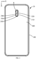
FIG. 2 is a rear view of the mobile terminal shown inFIG. 1 according to an embodiment. -
FIG. 3 is a side view of the mobile terminal shown inFIG. 2 . -
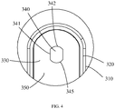
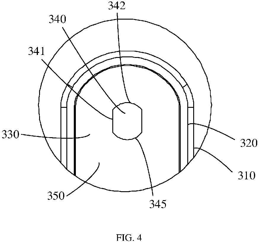
FIG. 4 is an enlarged view of the structure of the A part of the mobile terminal shown inFIG. 2 according to an embodiment. -
FIG. 5 is an exploded view of the mobile terminal shown inFIG. 1 . -
FIG. 6 is a perspective view of a sheet of the mobile terminal shown inFIG. 5 . -
FIG. 7 is a perspective view of a camera component of the mobile terminal shown inFIG. 5 . -
FIG. 8 is an exploded view of the camera component shown inFIG. 7 . -
FIG. 9 is a cross-sectional view of the camera component shown inFIG. 7 . -
FIG. 10 is a plan view of the camera component shown inFIG. 7 according to an embodiment. -
FIG. 11 is a top view of the camera component shown inFIG. 7 according to an embodiment. -
FIG. 12 is a top view of the camera component shown inFIG. 7 according to an embodiment. -
FIG. 13 is an enlarged view of the structure of the part A of the mobile terminal shown inFIG. 2 according to an embodiment. -
FIG. 14 is an enlarged view of the structure of the part A of the mobile terminal shown inFIG. 2 according to an embodiment. -
FIG. 15 is an enlarged view of the structure of the part A of the mobile terminal shown inFIG. 2 according to an embodiment. -
FIG. 16 is an enlarged view of the structure of the part A of the mobile terminal shown inFIG. 2 according to an embodiment. -
FIG. 17 is a rear view of the mobile terminal shown inFIG. 1 according to an embodiment. -
FIG. 18 is a side view of the mobile terminal shown inFIG. 17 . -
FIG. 19 is an enlarged view of the part B of the mobile terminal shown inFIG. 17 . - In order to facilitate understanding of the present disclosure, the present disclosure will be described more fully with reference to the drawings. The drawings show exemplary embodiments of the present disclosure. However, embodiments of the present disclosure can be implemented in many different forms and are not limited to the embodiments described herein. Rather, these embodiments are provided to provide a thorough and comprehensive understanding of the present disclosure.
- The term "terminal device" herein includes, but is not limited to, a device configured for receiving and/or transmitting communication signals which can be communicated in any one or more of the following connection methods:
- (1) connections using wired lines, such as Public Switched Telephone Networks (PSTN), Digital Subscriber Line (DSL), digital cable, direct cable connection;
- (2) connections via a wireless interface, such as a cellular network, a wireless local area network (WLAN), a digital television network such as a DVB-H network, a satellite network, and an AM-FM broadcast transmitter.
- A terminal device configured to communicate through a wireless interface may be referred to as a "mobile terminal". Examples of mobile terminals include, but are not limited to, the following electronic devices:
- (1) satellite phone or cellular phone;
- (2) personal Communications System (PCS) terminals which incorporate combine cellular radiotelephones with data processing, facsimile, and data communication capabilities;
- (3) radiotelephone, pager, Internet/Intranet access device, Web browser, memo pad, calendar, Personal Digital Assistant (PDA) equipped with a Global Positioning System (GPS) receiver;
- (4) conventional laptop and/or handheld receivers;
- (5) conventional laptop and/or handheld radiotelephone transceivers, etc.
- As shown in
FIG. 1 to FIG. 3 , in an embodiment, amobile terminal 10 is provided. Themobile terminal 10 may be a smart phone, a computer, or a tablet. In the following description, for example, themobile terminal 10 is a mobile phone. Themobile terminal 10 includes adisplay assembly 200, amiddle frame 100, abattery cover 300, and a main board (not shown). Thedisplay screen assembly 200 and thebattery cover 300 are respectively fixed on both sides of themiddle frame 100. Thedisplay screen assembly 200, themiddle housing frame 100 and thebattery cover 300 together form an external structure of themobile terminal 10. The main board is located inside themobile terminal 10, and controllers, storage units, power management units, baseband chips and other electronic components can be incorporated on the main board. - The
display screen assembly 200 can be used to display pictures or characters. The main board can control the operation of themobile terminal 10. It should be understood that when a user normally uses themobile terminal 10 to make and receive a call, the earpiece of themobile terminal 10 faces the user's ear, the microphone of themobile terminal 10 faces the user's mouth, and themobile terminal 10 can be close to perpendicular to the ground. The end facing upward is thetop end 111 of themobile terminal 10, the end facing down is thebottom end 113 of themobile terminal 10, the end facing left is theleft end 112 of themobile terminal 10, and the end facing right is theright end 114 of themobile terminal 10. The distance between theleft end 112 and theright end 114 defines the width of themobile terminal 10. The width direction of themobile terminal 10 is the Y direction. The distance between thetop end 111 and thebottom end 113 defines the length of themobile terminal 10. The length direction of themobile terminal 10 is the Z direction. The distance between the outer surface of thedisplay screen assembly 200 and the outer surface of thebattery cover 300 defines the thickness of themobile terminal 10, and the thickness direction of themobile terminal 10 is the X direction. - In an embodiment, the
display screen assembly 200 uses an LCD (Liquid Crystal Display) screen for displaying information. The LCD screen may be a TFT (Thin Film Transistor) screen or an IPS (In-Plane Switching) screen or a SLCD (Splice Liquid Crystal Display) screen. In another embodiment, thedisplay module 200 uses an OLED (Organic Light-Emitting Diode) screen for displaying information. The OLED screen may be an AMOLED (Active Matrix Organic Light Emitting Diode) screen or a Super AMOLED (Super Active Matrix Organic Light Emitting Diode) screen or a Super AMOLED Plus (Super Active Matrix Organic Light Emitting Diode Plus) screen. Under the control of controllers, thedisplay screen assembly 200 can display information and provide an operation interface for users. - As shown in
FIG. 5 , in an embodiment, themiddle frame 100 includes abezel 110 and amiddle plate 120. Thebezel 110 surrounds the outer periphery of themiddle plate 120 to form two installation spaces opposite to each other. Thedisplay screen assembly 200 is disposed in one of the installation spaces, and the other installation space is covered by thebattery cover 300. A main board (not shown) can be fixed on a side of themiddle board 120 facing thebattery cover 300. Acamera component 400 is provided in themobile terminal 10. A mountingslot 121 can be defined in themiddle plate 120, and thecamera component 400 may be fixed in the mountingslot 121. Themobile terminal 10 can include adecorative ring 320 and asheet 330. Thebattery cover 300 is provided with a throughslot 310, thedecorative ring 320 may pass through the throughslot 310 and be fixed in the throughslot 310. Thesheet 330 can be fixed on thedecorative ring 320, and thesheet 330 can cover thecamera component 400. Ambient light from the outer surface of thebattery cover 300 pass into thecamera module 400 through thesheet 330, so that thecamera module 400 can capture images or videos. - As shown in
FIGS. 4 and6 , in an embodiment of the present disclosure, thesheet 330 includes a light-transmittingregion 340 and a light-shieldingregion 350. The light-shieldingregion 350 surrounds the light-transmittingregion 340, and the light-transmittingregion 340 includesedge contour lines 345. It should be understood that theedge contour lines 345 can be the boundary between the light-shieldingregion 350 and the light-transmittingregion 340. The light transmittance of thelight transmitting region 340 can be greater than or equal to 75%, and the light transmittance of thelight shielding region 350 may be less than 75%. Theedge contour lines 345 include firststraight line segments 341 and firstarc line segments 342. The number of the firststraight line segments 341 is two, and the two firststraight line segments 341 are opposite to each other. The number of the firstarc line segments 342 is two, and the twofirst arc segments 342 are opposite to each other. It should be understood that the twofirst arc segments 342 are circular arcs and are located on the same circle. The firststraight line segments 341 and the firstarc line segments 342 are alternately connected, and the firststraight line segments 341 are located in a circle where the firstarc line segments 342 are located. It should be understood that, the region surrounded by the circle where the firstarc line segments 342 are located is cut by the two firststraight line segments 341, and the remaining region forms the light-transmittingregion 340. The light-transmittingregion 340 may not be a common square or circular region, but instead be a region where two opposite sides are straight lines and another two opposite sides are arcs. In this way, the light-transmittingregion 340 may occupy less space and reduce the width of thedecorative ring 320. - As shown in
FIGS. 7 to 9 , in an embodiment, thecamera component 400 includes alens 410, abase 420, afilter 430, asensor 440, and acircuit board 450. Thecircuit board 450 can be fixed to one side of thebase 420, and thesensor 440 can be fixed to a side of thecircuit board 450 facing thebase 420. Thelens 410 can be fixed to the other side of thebase 420, and thefilter 430 can be fixed to thebase 420 and located between thelens 410 and thesensor 440. - In the embodiment shown in
FIGS. 7 and9 , thelens 410 has acircular viewing angle 411 of thecamera component 400, thesensor 440 has asquare viewing angle 441 of thecamera component 400, and a region where thecircular viewing angle 411 and thesquare viewing angle 441 overlap is an effective region which forms the field ofview 460 of thecamera component 400, that is, the field ofview 460 is within thecircular viewing angle 411. It should be understood that the portion of thecircular viewing angle 411 outside theviewing angle 460 is outside the square viewing angle 441-the light in this portion may not be transmitted to thesensor 440 for use in imaging. The portion of thesquare viewing angle 441 outside theviewing angle 460 is outside the circular viewing angle 411-the light in this portion can be blocked by thelens 410 and may not pass to the inside of thelens 410. Although the portion is located within thesquare viewing angle 441, it may not be transmitted to thesensor 440 and may not be used for imaging due to the blocking of thelens 410. - In one embodiment, as shown in
FIG. 7 andFIG. 10 , thesquare viewing angle 441 may be completely within thecircular viewing angle 411, and then the field ofview 460 of thecamera component 400 is asquare viewing angle 441. In another embodiment, as shown inFIG. 11 , thesquare viewing angle 441 and thecircular viewing angle 411 partially overlap. The relationship between the positions of thecircular viewing angle 411 and thesquare viewing angle 441 and the size of the regions may be designed according to actual need, and are not specifically limited here. The field ofview 460 of thecamera component 400 is a portion where thesquare viewing angle 441 and thecircular viewing angle 411 overlap with each other. - The field of
view 460 intersects with the outer surface of thesheet 330 to formintersections 480. Theintersections 480 are located in the light-transmittingregion 340, so that the ambient light in the field ofview 460 from the outer surface side of thebattery cover 300 can pass through the light-transmittingregion 340 to the inside of thecamera component 400. Ambient light can then be transmitted to thesensor 440 to form images. The ambient light within the field ofview 460 is not blocked by the light-shieldingregion 350. - As shown in
FIG. 12 , the light-transmittingregion 340 may form a special-shapedviewing angle 470 on thecamera component 400. The shape of the special-shapedviewing angle 470 can be the same as the shape formed by theedge contour lines 345, and the field ofview 460 inFIG. 10 and the field of view inFIG. 11 are all located in the special-shapedviewing angle 470 inFIG. 12 , so that the ambient light in the field ofview 460 can pass through the light-transmittingregion 340 and not be blocked. - In an embodiment, the first
straight line segments 341 can be partially or entirely within thecircular viewing angle 411. In other words, the firststraight line segments 341 may be partially or entirely within the intersections where thecircular viewing angle 411 and the outer surface of thesheet 330 intersect with each other. The region surrounded by the intersections where thecircular viewing angle 411 and the outer surface of thesheet 330 intersect with each other is cut is cut by two firststraight line segments 341, so that the area of the light-transmittingregion 340 is smaller than that of the traditional circular light-transmitting region. Accordingly, the light-transmittingregion 340 may occupy less space, which can advantageously reduce the width of thedecorative ring 320. - As shown in
FIG. 7 andFIG. 10 , in an embodiment, thesquare viewing angle 441 is in the region of thecircular viewing angle 411. Thesquare viewing angle 441 may or may not intersect thecircular viewing angle 411, and embodiments of the present disclosure do not impose specific limitations on this. In this embodiment, the field ofview 460 of thecamera component 400 is thesquare viewing angle 441. Theintersections 480 include two secondstraight line segments 481 and two thirdstraight line segments 482, two secondstraight line segments 481 are oppositely arranged, two thirdstraight line segments 482 are oppositely arranged, and the secondstraight line segments 481 and the thirdstraight line segments 482 are arranged adjacently and connected end to end to form a square structure. - As shown in
FIG. 13 , in an embodiment, theintersections 480 can be located inside the region surrounded by theedge contour lines 345, that is, theintersections 480 are located in the light-transmittingregion 340. The secondstraight line segments 481 and the firststraight line segments 341 are parallel, the thirdstraight line segments 482 does not extend beyond theedge contour lines 345. The circle formed by thecircular viewing angle 411 on the outer surface of thesheet 330 may be located between the circle where thefirst arc segments 342 are located and theintersections 480. A portion of the firststraight segments 341 can be located within thecircular viewing angle 411. A portion of thecircular viewing angle 411 can be within the light-transmittingregion 340, and the remaining portion of thecircular viewing angle 411 can be outside the light-transmittingregion 340 because the remaining portion is cut off by a part of the firststraight line segments 341. The size of the light-transmittingregion 340 in the width direction of themobile terminal 10, that is, the size in the Y direction can be smaller than the diameter of thecircular viewing angle 411 at the outer surface of thesheet 330. This can beneficially reduce the size of the light-transmittingregion 340 in the width direction of themobile terminal 10, that is, the size in the Y direction. Accordingly, the size of thedecorative ring 320 and the size of thesheet 330 can be reduced. -
FIG. 14 depicts another embodiment whereintersections 480 can be located in the region surrounded by theedge contour lines 345. That is, theintersections 480 can be located in the light-transmittingregion 340. The secondstraight line segments 481 and the firststraight line segments 341 overlap with each other, and the thirdstraight line segments 482 do not extend beyond theedge contour lines 345. Thecircular viewing angle 411 overlaps with the circle where the firstarc line segments 342 are located on the outer surface of thesheet 330. The firststraight line segments 341 may all be located in thecircular viewing angle 411. A part of thecircular viewing angle 411 can be located in the light-transmittingregion 340, and a remaining portion of thecircular viewing angle 411 be located outside the light-transmittingregion 340 because the remaining portion is cut off by the firststraight line segments 341. The size of the light-transmittingregion 340 in the width direction of themobile terminal 10, that is, the size in the Y direction can be smaller than the diameter of thecircular viewing angle 411 at the outer surface of thesheet 330. Accordingly, the size of the light-transmittingregion 340 in the width direction of themobile terminal 10, that is, the size of the light-transmittingregion 340 in the Y direction can be reduced, which can callow the size of thedecorative ring 320 and the size of thesheet 330 to be reduced. - As shown in
FIG. 11 , in an embodiment, thesquare viewing angle 441 and thecircular viewing angle 411 partially overlap. With reference back toFIG. 14 , the intersections where theviewing angle 460 of thecamera component 400 and the outer surface of thesheet 330 intersect with each other form a square structure with four corners being curved. Theintersections 480 include two secondstraight line segments 481, two thirdstraight line segments 482, and four secondarc line segments 483. Two secondstraight line segments 481 are arranged opposite one another, and the two thirdstraight line segments 482 are arranged opposite one another. Each of thesecond arc segments 483 is connected between one of secondstraight line segments 481 and one of the thirdstraight line segments 482, which are adjacent one another, and the foursecond arc segments 483 are located on the same circle. - In an embodiment shown in
FIG. 15 ,intersections 480 are located inside the region surrounded by theedge contour lines 345, that is, theintersections 480 are located in the light-transmittingregion 340. The secondstraight line segments 481 and the firststraight line segments 341 are parallel, thesecond arc segments 483 and thefirst arc segments 342 are parallel, and the thirdstraight line segments 482 do not extend beyond theedge contour lines 345. Thecircular viewing angle 411 overlaps with the circle where thesecond arc segments 483 are located on the outer surface of thesheet 330. A portion of the firststraight segments 341 can be located in thecircular viewing angle 411. A portion of thecircular viewing angle 411 may be located in the light-transmittingregion 340 and a remaining portion may be outside the light-transmittingregion 340 because the remaining portion is cut off by the firststraight line segments 341. The size of the light-transmittingregion 340 in the width direction of themobile terminal 10, that is, size of the light-transmittingregion 340 in the Y direction can be smaller than the diameter of thecircular viewing angle 411 at the outer surface of thesheet 330, which can beneficially reduce the size of the light-transmittingregion 340 in the width direction of themobile terminal 10, that is, size of the light-transmittingregion 340 in the Y direction. Accordingly, the size of thedecorative ring 320 and the size of thesheet 330 can be reduced. -
FIG. 16 illustrates another embodiment where the secondstraight line segments 481 overlap with the firststraight line segments 341, thesecond arc segments 483 overlap with thefirst arc segments 342, and the ends of the thirdstraight segments 482 intersect with thefirst arc segments 342 and do not extend beyond thefirst arc segments 342. Thecircular viewing angle 411 overlaps with the circle where the firstarc line segments 342 are located on the outer surface of thesheet 330. The firststraight line segments 341 can all be within thecircular viewing angle 411. A part of thecircular viewing angle 411 can be within the light-transmittingregion 340, and a remaining part can be outside the light-transmittingregion 340 because the remaining part is cut off by a part of the firststraight line segments 341. The size of the light-transmittingregion 340 in the width direction of themobile terminal 10, that is, the size of the light-transmittingregion 340 in the Y direction can be smaller than the diameter of thecircular viewing angle 411 on the outer surface of thesheet 330. Accordingly, the size of the light-transmittingregion 340 in the width direction of themobile terminal 10, that is, the size of the light-transmittingregion 340 in the Y direction may be reduced, thereby reducing the size of thedecorative ring 320 and the size of thesheet 330. - As shown in
FIGS. 2 and3 , in an embodiment, the number ofcamera components 400 is n, and n is greater than or equal to 1. As shown inFIG. 2 , n is 3, and the threecamera components 400 are along the length direction of themobile terminal 10, i.e., the Z direction. The firststraight line segments 341 are arranged along the length direction of themobile terminal 10, that is, the Z direction. Compared with the circular light-transmitting region, the light-transmittingregion 340 in this embodiment occupies less space in the width direction, that is, the Y direction, so that the width of thedecorative ring 320 can be reduced. Under the premise of being compatible with intersecting effective regions, the light-transmittingregion 340 can also be designed with more shapes. In another embodiment, then camera assemblies 400 are arranged along the width direction of themobile terminal 10, that is, the Y direction, and the firststraight line segments 341 are arranged along the width direction of themobile terminal 10, that is, the Y direction. - As shown in
FIG. 17 to FIG. 19 , in an embodiment, a part of thebattery cover 300 is transparent, and this region can be form asheet 330 including a light-transmittingregion 340 and a light-shieldingregion 350. The step for providing the throughslot 310 on thebattery cover 300 can be omitted. Theedge contour lines 345 of the light-transmittingregion 340 in this embodiment are the same as theedge contour lines 345 described in the above embodiments. - In the
mobile terminal 10 of the present disclosure, theedge contour lines 345 of the light-transmittingregion 340 of thesheet 330 may not form a traditional circle or square shape, but instead form a shape that is a combination of a circle and a square. Specifically, the shape can be defined byedge contour lines 345 including firststraight segments 341 andfirst arc segments 342. The firststraight line segments 341 can be partially or entirely located within thecircular viewing angle 411, and the ambient light within the field ofview 460 of thecamera component 400 can enter thecamera component 400 through the light-transmittingregion 340. The area of the light-transmittingregion 340 may be reduced while the light-transmitting region can meet the field ofview 460 of thecamera component 400, and the size of thedecorative ring 320 and the size of thesheet 330 as well as the throughslot 310 can be reduced. As a result, the strength of thebattery cover 300 can be increased, and the physical form of themobile terminal 10 can be changed to improve aesthetics of the product. - The technical features of the embodiments described above can be arbitrarily combined. In order to simplify the description, all possible combinations of the technical features in the above embodiments have not been described. However, as long as there is no contradiction in the combination of these technical features, such combination should be considered as falling within the scope of the present disclosure.
The above-mentioned embodiments provide specific and detailed implementation manners of the present disclosure, but they should not be understood as limiting the scope of present disclosure. It should be noted that, for those of ordinary skill in the art, without departing from the concept of the present disclosure, modifications and improvements can be made, which all fall within the protection scope of the present disclosure. Therefore, the scope of the present disclosure is defined by the appended claims.
Claims (15)
- A mobile terminal, comprising:one or more camera components located inside the mobile terminal, each of the one or more camera components comprising a lens having a circular viewing angle, and each of the camera one or more camera components having a field of view, and the field of view being within the circular viewing angle; anda sheet that covers the one or more camera components, the sheet comprising a light-transmitting region and a light-shielding region, the light-shielding region surrounding the light-transmitting region, and the field of view intersecting with the sheet to form intersections located in the light-transmitting region;wherein the light-transmitting region comprises edge contour lines comprising first straight line segments and first arc line segments connected to each other, the first straight line segments being located in a circle in which the first arc line segments are located, and the first straight line segments being at least partially located within the circular viewing angle;wherein the one or more camera components comprise a sensor that has a square viewing angle, and a portion where the circular viewing angle and the square viewing angle overlap forms the field of view.
- The mobile terminal according to claim 1, wherein there are two of the first straight line segments, and the two first straight line segments are arranged opposite one another;
wherein there are two of the first arc line segments, and the two first arc segments are arranged opposite one another;
wherein ends of each of the first straight segments are directly connected to ends of the first arc segments such that the first straight segments and the first arc segments are alternately connected to one another. - The mobile terminal according to claim 2, wherein the intersections form a square structure with four corners being curved, and the intersections comprise two second straight line segments, two third straight line segments, and four second arc segments;
wherein the two second straight line segments are arranged opposite one another, the two third straight line segments are arranged opposite one another, and each of the second arc segments is connected between one of second straight line segments and one of the third straight line segments which are adjacent to one another. - The mobile terminal according to claim 3, wherein one of the following:the intersections are located inside a region surrounded by the edge contour lines, the second straight line segments are parallel to the first straight line segments, and the second arc segments are parallel to the first arc segments; andthe second straight line segments overlap with the first straight line segments, and the second arc segments overlap with the first arc segments.
- The mobile terminal according to claim 2, wherein the intersections form a square structure, and the intersections comprise two second straight line segments and two third straight line segments, the two second straight line segments are arranged opposite one another, the two third straight line segments are arranged opposite one another, and the second straight line segments and the third straight line segments are arranged one another.
- The mobile terminal according to claim 5, wherein one of the following:the intersections are located inside a region surrounded by the edge contour lines, and the second straight line segments are parallel to the first straight line segments; andthe intersections are located in a region surrounded by the edge contour lines, and the second straight line segments overlap with the first straight line segments.
- The mobile terminal according to claim 1, wherein the one or more camera components includes n camera components, n being greater than or equal to 1;
wherein one of the following:the n camera components are arranged along a length direction of the mobile terminal, and the first straight line segments are provided along the length direction of the mobile terminal; andthe n camera components are arranged along the width direction of the mobile terminal, and the first straight line segments are provided along the width direction of the mobile terminal. - The mobile terminal according to claim 1, further comprising a battery cover and a decorative ring, wherein a through slot is formed on the battery cover, and the decorative ring passes through the through slot and is fixed in the through slot, and the sheet is fixed to the decorative ring.
- The mobile terminal according to claim 1, further comprising a battery cover, wherein a part of the battery cover forms the sheet.
- A mobile terminal, comprising:one or more camera components located inside the mobile terminal, each of the camera components comprising a lens and a sensor, the lens having a circular viewing angle, the sensor having a square viewing angle, and at least part of the square viewing angle is within the circular viewing angle; anda sheet covering the one or more camera components, wherein the sheet comprises a light-transmitting region and a light-shielding region, the light-shielding region surrounding the light-transmitting region;wherein the light-transmitting region comprises edge contour lines comprising first straight line segments and first arc line segments connected to each other, the first straight line segments being located in a circle in which the first arc line segments are located, the square viewing angle being entirely within the light-transmitting region, a part of the circular viewing angle being within the light-transmitting region, and another part of the circular viewing angle being outside the light-transmitting region;wherein a portion where the circular viewing angle and the square viewing angle overlap forms the field of view of the one or more camera components, and the field of view intersects with the sheet to form intersections located in the light-transmitting region.
- The mobile terminal according to claim 10, wherein there are two of the first straight line segments, and the two first straight line segments are arranged opposite one another;
wherein there are two of the first arc line segments, and the two first arc segments are arranged opposite one another;
wherein ends of each of the first straight segments are directly connected to ends of the first arc segments such that the first straight segments and the first arc segments are alternately connected to one another. - The mobile terminal according to claim 11, wherein the intersections form a square structure with four corners being curved, and the intersections comprise two second straight line segments, two third straight line segments, and four second arc segments;
wherein the two second straight line segments are arranged opposite to one another, the two third straight line segments are arranged opposite to one another, and each of the second arc segments is connected between one of second straight line segments and one of the third straight line segments which are adjacent to one another. - The mobile terminal according to claim 12, wherein one of the following:the intersections are located inside a region surrounded by the edge contour lines, the second straight line segments are parallel to the first straight line segments, and the second arc segments are parallel to the first arc segments; andthe second straight line segments overlap with the first straight line segments, and the second arc segments overlap with the first arc segments.
- The mobile terminal according to claim 12, wherein the intersections form a square structure, and the intersections comprise two second straight line segments and two third straight line segments, the two second straight line segments are arranged opposite one another, the two third straight line segments are arranged opposite one another, and the second straight line segments and the third straight line segments are adjacent one another.
- The mobile terminal according to claim 14, wherein one of the following:the intersections are located inside a region surrounded by the edge contour lines, and the second straight line segments are parallel to the first straight line segments; andthe intersections are located in a region surrounded by the edge contour lines, and the second straight line segments overlap with the first straight line segments.
Applications Claiming Priority (1)
| Application Number | Priority Date | Filing Date | Title |
|---|---|---|---|
| CN201920881910.3U CN210093262U (en) | 2019-06-12 | 2019-06-12 | Mobile terminal |
Publications (2)
| Publication Number | Publication Date |
|---|---|
| EP3751340A1 true EP3751340A1 (en) | 2020-12-16 |
| EP3751340B1 EP3751340B1 (en) | 2023-06-14 |
Family
ID=69482631
Family Applications (1)
| Application Number | Title | Priority Date | Filing Date |
|---|---|---|---|
| EP20179594.5A Active EP3751340B1 (en) | 2019-06-12 | 2020-06-12 | Mobile terminal |
Country Status (4)
| Country | Link |
|---|---|
| US (1) | US11243453B2 (en) |
| EP (1) | EP3751340B1 (en) |
| CN (1) | CN210093262U (en) |
| WO (1) | WO2020249055A1 (en) |
Families Citing this family (2)
| Publication number | Priority date | Publication date | Assignee | Title |
|---|---|---|---|---|
| CN108900772A (en) * | 2018-07-19 | 2018-11-27 | 维沃移动通信有限公司 | A kind of mobile terminal and image capturing method |
| CN210093262U (en) * | 2019-06-12 | 2020-02-18 | Oppo广东移动通信有限公司 | Mobile terminal |
Citations (5)
| Publication number | Priority date | Publication date | Assignee | Title |
|---|---|---|---|---|
| US20110319131A1 (en) * | 2010-06-25 | 2011-12-29 | Youngsoo An | Mobile terminal capable of providing multiplayer game and operating method thereof |
| CN108600465A (en) * | 2018-06-30 | 2018-09-28 | 上海爱优威软件开发有限公司 | A kind of terminal device with the lower camera of screen |
| CN109040570A (en) * | 2018-10-26 | 2018-12-18 | Oppo(重庆)智能科技有限公司 | CCD camera assembly, flash lamp component and the electronic equipment of electronic equipment |
| CN109462675A (en) * | 2018-12-28 | 2019-03-12 | Oppo广东移动通信有限公司 | shell assembly and mobile terminal |
| CN208956096U (en) * | 2018-08-24 | 2019-06-07 | Oppo广东移动通信有限公司 | Mobile terminal |
Family Cites Families (17)
| Publication number | Priority date | Publication date | Assignee | Title |
|---|---|---|---|---|
| JP3988051B2 (en) * | 2003-10-14 | 2007-10-10 | ソニー株式会社 | Imaging device |
| EP2270567A4 (en) | 2008-04-16 | 2014-08-06 | Komatsulite Mfg Co Ltd | Imaging lens unit |
| CN203261364U (en) | 2012-11-30 | 2013-10-30 | 金电实业(深圳)有限公司 | Novel waterproof mobile phone cover |
| WO2015068591A1 (en) * | 2013-11-06 | 2015-05-14 | 株式会社リコー | Image-capturing device |
| EP3937246B1 (en) | 2015-09-29 | 2025-11-19 | Dai Nippon Printing Co., Ltd. | Lens sheet, lens sheet unit, imaging module, imaging device |
| CN106027706A (en) | 2016-07-14 | 2016-10-12 | 惠州Tcl移动通信有限公司 | Mobile terminal and photographing device thereof |
| CN106161897B (en) | 2016-07-29 | 2019-04-12 | 维沃移动通信有限公司 | A camera and mobile terminal |
| US10712635B2 (en) * | 2016-10-14 | 2020-07-14 | Beastgrip, Co | Interchangeable lens mount insert |
| CN206339769U (en) | 2016-12-10 | 2017-07-18 | 瑞声科技(新加坡)有限公司 | Camera lens module |
| CN206332711U (en) | 2016-12-29 | 2017-07-14 | 东莞市鸿瀚电子材料有限公司 | A lens waterproof device dedicated to waterproof smartphones |
| US10564425B2 (en) * | 2017-02-27 | 2020-02-18 | Snap Inc. | Processing a media content based on device movement |
| CN108519657A (en) | 2018-04-16 | 2018-09-11 | 维沃移动通信有限公司 | A kind of camera lens module and mobile terminal |
| US10389982B1 (en) * | 2018-04-23 | 2019-08-20 | Kuna Systems Corporation | Video security camera with two fields of view |
| CN208433994U (en) * | 2018-04-26 | 2019-01-25 | Oppo广东移动通信有限公司 | Terminal display assembly and mobile terminal |
| CN208401902U (en) * | 2018-04-26 | 2019-01-18 | Oppo广东移动通信有限公司 | terminal display screen component and mobile terminal |
| US10667587B1 (en) * | 2018-11-30 | 2020-06-02 | BobjGear, LLC | Rear camera hood |
| CN210093262U (en) | 2019-06-12 | 2020-02-18 | Oppo广东移动通信有限公司 | Mobile terminal |
-
2019
- 2019-06-12 CN CN201920881910.3U patent/CN210093262U/en not_active Expired - Fee Related
-
2020
- 2020-06-02 US US16/890,248 patent/US11243453B2/en not_active Expired - Fee Related
- 2020-06-11 WO PCT/CN2020/095677 patent/WO2020249055A1/en not_active Ceased
- 2020-06-12 EP EP20179594.5A patent/EP3751340B1/en active Active
Patent Citations (5)
| Publication number | Priority date | Publication date | Assignee | Title |
|---|---|---|---|---|
| US20110319131A1 (en) * | 2010-06-25 | 2011-12-29 | Youngsoo An | Mobile terminal capable of providing multiplayer game and operating method thereof |
| CN108600465A (en) * | 2018-06-30 | 2018-09-28 | 上海爱优威软件开发有限公司 | A kind of terminal device with the lower camera of screen |
| CN208956096U (en) * | 2018-08-24 | 2019-06-07 | Oppo广东移动通信有限公司 | Mobile terminal |
| CN109040570A (en) * | 2018-10-26 | 2018-12-18 | Oppo(重庆)智能科技有限公司 | CCD camera assembly, flash lamp component and the electronic equipment of electronic equipment |
| CN109462675A (en) * | 2018-12-28 | 2019-03-12 | Oppo广东移动通信有限公司 | shell assembly and mobile terminal |
Also Published As
| Publication number | Publication date |
|---|---|
| US20200393740A1 (en) | 2020-12-17 |
| EP3751340B1 (en) | 2023-06-14 |
| WO2020249055A1 (en) | 2020-12-17 |
| CN210093262U (en) | 2020-02-18 |
| US11243453B2 (en) | 2022-02-08 |
Similar Documents
| Publication | Publication Date | Title |
|---|---|---|
| US10917506B2 (en) | Terminal display assembly and mobile terminal | |
| US10620665B2 (en) | Terminal display assembly and mobile terminal | |
| CN108234701B (en) | Display screen module and mobile terminal | |
| CN107948365A (en) | Display module and mobile terminal | |
| CN110120991B (en) | Terminal display screen assembly and mobile terminal | |
| US20210202535A1 (en) | Display panel and intelligent terminal | |
| CN108040143A (en) | Cover plate, display module and mobile terminal | |
| US11243453B2 (en) | Mobile terminal | |
| CN112838112B (en) | Display panel and display device | |
| WO2020029718A1 (en) | Screen, electronic apparatus, and method for manufacturing screen | |
| CN108234697A (en) | Cover plate assembly, display module and mobile terminal | |
| CN210143026U (en) | Cover plate, display module and mobile terminal | |
| CN210183364U (en) | mobile terminal | |
| CN107819911B (en) | Mobile terminal and cover plate thereof | |
| US20220006887A1 (en) | Terminal device, mobile terminal and shell assembly thereof | |
| US12069194B2 (en) | Display panel and electronic device | |
| US20250004257A1 (en) | Lens device and electronic device | |
| CN111477105B (en) | Display modules and electronic equipment | |
| CN209659376U (en) | Shell components and mobile terminals | |
| CN118488745A (en) | Display module, preparation method thereof and electronic device | |
| HK40010397A (en) | Terminal display screen assembly and mobile terminal | |
| HK40011010A (en) | Terminal display screen assembly and mobile terminal | |
| WO2020057173A1 (en) | Rear cover and mobile terminal |
Legal Events
| Date | Code | Title | Description |
|---|---|---|---|
| PUAI | Public reference made under article 153(3) epc to a published international application that has entered the european phase |
Free format text: ORIGINAL CODE: 0009012 |
|
| STAA | Information on the status of an ep patent application or granted ep patent |
Free format text: STATUS: THE APPLICATION HAS BEEN PUBLISHED |
|
| AK | Designated contracting states |
Kind code of ref document: A1 Designated state(s): AL AT BE BG CH CY CZ DE DK EE ES FI FR GB GR HR HU IE IS IT LI LT LU LV MC MK MT NL NO PL PT RO RS SE SI SK SM TR |
|
| AX | Request for extension of the european patent |
Extension state: BA ME |
|
| STAA | Information on the status of an ep patent application or granted ep patent |
Free format text: STATUS: REQUEST FOR EXAMINATION WAS MADE |
|
| 17P | Request for examination filed |
Effective date: 20210422 |
|
| RBV | Designated contracting states (corrected) |
Designated state(s): AL AT BE BG CH CY CZ DE DK EE ES FI FR GB GR HR HU IE IS IT LI LT LU LV MC MK MT NL NO PL PT RO RS SE SI SK SM TR |
|
| STAA | Information on the status of an ep patent application or granted ep patent |
Free format text: STATUS: EXAMINATION IS IN PROGRESS |
|
| 17Q | First examination report despatched |
Effective date: 20210604 |
|
| REG | Reference to a national code |
Ref country code: DE Ref legal event code: R079 Free format text: PREVIOUS MAIN CLASS: G03B0017020000 Ipc: G03B0011040000 Ref document number: 602020012431 Country of ref document: DE |
|
| GRAP | Despatch of communication of intention to grant a patent |
Free format text: ORIGINAL CODE: EPIDOSNIGR1 |
|
| STAA | Information on the status of an ep patent application or granted ep patent |
Free format text: STATUS: GRANT OF PATENT IS INTENDED |
|
| RIC1 | Information provided on ipc code assigned before grant |
Ipc: G03B 30/00 20210101ALN20230120BHEP Ipc: G03B 17/02 20060101ALI20230120BHEP Ipc: G03B 11/04 20060101AFI20230120BHEP |
|
| INTG | Intention to grant announced |
Effective date: 20230223 |
|
| GRAS | Grant fee paid |
Free format text: ORIGINAL CODE: EPIDOSNIGR3 |
|
| GRAA | (expected) grant |
Free format text: ORIGINAL CODE: 0009210 |
|
| STAA | Information on the status of an ep patent application or granted ep patent |
Free format text: STATUS: THE PATENT HAS BEEN GRANTED |
|
| AK | Designated contracting states |
Kind code of ref document: B1 Designated state(s): AL AT BE BG CH CY CZ DE DK EE ES FI FR GB GR HR HU IE IS IT LI LT LU LV MC MK MT NL NO PL PT RO RS SE SI SK SM TR |
|
| REG | Reference to a national code |
Ref country code: CH Ref legal event code: EP |
|
| P01 | Opt-out of the competence of the unified patent court (upc) registered |
Effective date: 20230525 |
|
| REG | Reference to a national code |
Ref country code: DE Ref legal event code: R096 Ref document number: 602020012431 Country of ref document: DE |
|
| REG | Reference to a national code |
Ref country code: AT Ref legal event code: REF Ref document number: 1579658 Country of ref document: AT Kind code of ref document: T Effective date: 20230715 |
|
| REG | Reference to a national code |
Ref country code: LT Ref legal event code: MG9D |
|
| REG | Reference to a national code |
Ref country code: NL Ref legal event code: MP Effective date: 20230614 |
|
| PG25 | Lapsed in a contracting state [announced via postgrant information from national office to epo] |
Ref country code: SE Free format text: LAPSE BECAUSE OF FAILURE TO SUBMIT A TRANSLATION OF THE DESCRIPTION OR TO PAY THE FEE WITHIN THE PRESCRIBED TIME-LIMIT Effective date: 20230614 Ref country code: NO Free format text: LAPSE BECAUSE OF FAILURE TO SUBMIT A TRANSLATION OF THE DESCRIPTION OR TO PAY THE FEE WITHIN THE PRESCRIBED TIME-LIMIT Effective date: 20230914 Ref country code: ES Free format text: LAPSE BECAUSE OF FAILURE TO SUBMIT A TRANSLATION OF THE DESCRIPTION OR TO PAY THE FEE WITHIN THE PRESCRIBED TIME-LIMIT Effective date: 20230614 |
|
| REG | Reference to a national code |
Ref country code: AT Ref legal event code: MK05 Ref document number: 1579658 Country of ref document: AT Kind code of ref document: T Effective date: 20230614 |
|
| PG25 | Lapsed in a contracting state [announced via postgrant information from national office to epo] |
Ref country code: RS Free format text: LAPSE BECAUSE OF FAILURE TO SUBMIT A TRANSLATION OF THE DESCRIPTION OR TO PAY THE FEE WITHIN THE PRESCRIBED TIME-LIMIT Effective date: 20230614 Ref country code: NL Free format text: LAPSE BECAUSE OF FAILURE TO SUBMIT A TRANSLATION OF THE DESCRIPTION OR TO PAY THE FEE WITHIN THE PRESCRIBED TIME-LIMIT Effective date: 20230614 Ref country code: LV Free format text: LAPSE BECAUSE OF FAILURE TO SUBMIT A TRANSLATION OF THE DESCRIPTION OR TO PAY THE FEE WITHIN THE PRESCRIBED TIME-LIMIT Effective date: 20230614 Ref country code: LT Free format text: LAPSE BECAUSE OF FAILURE TO SUBMIT A TRANSLATION OF THE DESCRIPTION OR TO PAY THE FEE WITHIN THE PRESCRIBED TIME-LIMIT Effective date: 20230614 Ref country code: HR Free format text: LAPSE BECAUSE OF FAILURE TO SUBMIT A TRANSLATION OF THE DESCRIPTION OR TO PAY THE FEE WITHIN THE PRESCRIBED TIME-LIMIT Effective date: 20230614 Ref country code: GR Free format text: LAPSE BECAUSE OF FAILURE TO SUBMIT A TRANSLATION OF THE DESCRIPTION OR TO PAY THE FEE WITHIN THE PRESCRIBED TIME-LIMIT Effective date: 20230915 |
|
| PG25 | Lapsed in a contracting state [announced via postgrant information from national office to epo] |
Ref country code: FI Free format text: LAPSE BECAUSE OF FAILURE TO SUBMIT A TRANSLATION OF THE DESCRIPTION OR TO PAY THE FEE WITHIN THE PRESCRIBED TIME-LIMIT Effective date: 20230614 |
|
| PG25 | Lapsed in a contracting state [announced via postgrant information from national office to epo] |
Ref country code: SK Free format text: LAPSE BECAUSE OF FAILURE TO SUBMIT A TRANSLATION OF THE DESCRIPTION OR TO PAY THE FEE WITHIN THE PRESCRIBED TIME-LIMIT Effective date: 20230614 |
|
| PG25 | Lapsed in a contracting state [announced via postgrant information from national office to epo] |
Ref country code: IS Free format text: LAPSE BECAUSE OF FAILURE TO SUBMIT A TRANSLATION OF THE DESCRIPTION OR TO PAY THE FEE WITHIN THE PRESCRIBED TIME-LIMIT Effective date: 20231014 |
|
| PG25 | Lapsed in a contracting state [announced via postgrant information from national office to epo] |
Ref country code: SM Free format text: LAPSE BECAUSE OF FAILURE TO SUBMIT A TRANSLATION OF THE DESCRIPTION OR TO PAY THE FEE WITHIN THE PRESCRIBED TIME-LIMIT Effective date: 20230614 Ref country code: SK Free format text: LAPSE BECAUSE OF FAILURE TO SUBMIT A TRANSLATION OF THE DESCRIPTION OR TO PAY THE FEE WITHIN THE PRESCRIBED TIME-LIMIT Effective date: 20230614 Ref country code: RO Free format text: LAPSE BECAUSE OF FAILURE TO SUBMIT A TRANSLATION OF THE DESCRIPTION OR TO PAY THE FEE WITHIN THE PRESCRIBED TIME-LIMIT Effective date: 20230614 Ref country code: PT Free format text: LAPSE BECAUSE OF FAILURE TO SUBMIT A TRANSLATION OF THE DESCRIPTION OR TO PAY THE FEE WITHIN THE PRESCRIBED TIME-LIMIT Effective date: 20231016 Ref country code: IS Free format text: LAPSE BECAUSE OF FAILURE TO SUBMIT A TRANSLATION OF THE DESCRIPTION OR TO PAY THE FEE WITHIN THE PRESCRIBED TIME-LIMIT Effective date: 20231014 Ref country code: EE Free format text: LAPSE BECAUSE OF FAILURE TO SUBMIT A TRANSLATION OF THE DESCRIPTION OR TO PAY THE FEE WITHIN THE PRESCRIBED TIME-LIMIT Effective date: 20230614 Ref country code: CZ Free format text: LAPSE BECAUSE OF FAILURE TO SUBMIT A TRANSLATION OF THE DESCRIPTION OR TO PAY THE FEE WITHIN THE PRESCRIBED TIME-LIMIT Effective date: 20230614 Ref country code: AT Free format text: LAPSE BECAUSE OF FAILURE TO SUBMIT A TRANSLATION OF THE DESCRIPTION OR TO PAY THE FEE WITHIN THE PRESCRIBED TIME-LIMIT Effective date: 20230614 |
|
| PG25 | Lapsed in a contracting state [announced via postgrant information from national office to epo] |
Ref country code: PL Free format text: LAPSE BECAUSE OF FAILURE TO SUBMIT A TRANSLATION OF THE DESCRIPTION OR TO PAY THE FEE WITHIN THE PRESCRIBED TIME-LIMIT Effective date: 20230614 |
|
| REG | Reference to a national code |
Ref country code: DE Ref legal event code: R097 Ref document number: 602020012431 Country of ref document: DE |
|
| PLBE | No opposition filed within time limit |
Free format text: ORIGINAL CODE: 0009261 |
|
| STAA | Information on the status of an ep patent application or granted ep patent |
Free format text: STATUS: NO OPPOSITION FILED WITHIN TIME LIMIT |
|
| PG25 | Lapsed in a contracting state [announced via postgrant information from national office to epo] |
Ref country code: DK Free format text: LAPSE BECAUSE OF FAILURE TO SUBMIT A TRANSLATION OF THE DESCRIPTION OR TO PAY THE FEE WITHIN THE PRESCRIBED TIME-LIMIT Effective date: 20230614 |
|
| PG25 | Lapsed in a contracting state [announced via postgrant information from national office to epo] |
Ref country code: SI Free format text: LAPSE BECAUSE OF FAILURE TO SUBMIT A TRANSLATION OF THE DESCRIPTION OR TO PAY THE FEE WITHIN THE PRESCRIBED TIME-LIMIT Effective date: 20230614 |
|
| 26N | No opposition filed |
Effective date: 20240315 |
|
| PG25 | Lapsed in a contracting state [announced via postgrant information from national office to epo] |
Ref country code: SI Free format text: LAPSE BECAUSE OF FAILURE TO SUBMIT A TRANSLATION OF THE DESCRIPTION OR TO PAY THE FEE WITHIN THE PRESCRIBED TIME-LIMIT Effective date: 20230614 Ref country code: IT Free format text: LAPSE BECAUSE OF FAILURE TO SUBMIT A TRANSLATION OF THE DESCRIPTION OR TO PAY THE FEE WITHIN THE PRESCRIBED TIME-LIMIT Effective date: 20230614 |
|
| PG25 | Lapsed in a contracting state [announced via postgrant information from national office to epo] |
Ref country code: BG Free format text: LAPSE BECAUSE OF FAILURE TO SUBMIT A TRANSLATION OF THE DESCRIPTION OR TO PAY THE FEE WITHIN THE PRESCRIBED TIME-LIMIT Effective date: 20230614 |
|
| PG25 | Lapsed in a contracting state [announced via postgrant information from national office to epo] |
Ref country code: BG Free format text: LAPSE BECAUSE OF FAILURE TO SUBMIT A TRANSLATION OF THE DESCRIPTION OR TO PAY THE FEE WITHIN THE PRESCRIBED TIME-LIMIT Effective date: 20230614 |
|
| REG | Reference to a national code |
Ref country code: DE Ref legal event code: R119 Ref document number: 602020012431 Country of ref document: DE |
|
| PG25 | Lapsed in a contracting state [announced via postgrant information from national office to epo] |
Ref country code: MC Free format text: LAPSE BECAUSE OF FAILURE TO SUBMIT A TRANSLATION OF THE DESCRIPTION OR TO PAY THE FEE WITHIN THE PRESCRIBED TIME-LIMIT Effective date: 20230614 |
|
| REG | Reference to a national code |
Ref country code: CH Ref legal event code: PL |
|
| PG25 | Lapsed in a contracting state [announced via postgrant information from national office to epo] |
Ref country code: LU Free format text: LAPSE BECAUSE OF NON-PAYMENT OF DUE FEES Effective date: 20240612 |
|
| GBPC | Gb: european patent ceased through non-payment of renewal fee |
Effective date: 20240612 |
|
| PG25 | Lapsed in a contracting state [announced via postgrant information from national office to epo] |
Ref country code: DE Free format text: LAPSE BECAUSE OF NON-PAYMENT OF DUE FEES Effective date: 20250101 |
|
| PG25 | Lapsed in a contracting state [announced via postgrant information from national office to epo] |
Ref country code: IE Free format text: LAPSE BECAUSE OF NON-PAYMENT OF DUE FEES Effective date: 20240612 |
|
| PG25 | Lapsed in a contracting state [announced via postgrant information from national office to epo] |
Ref country code: BE Free format text: LAPSE BECAUSE OF NON-PAYMENT OF DUE FEES Effective date: 20240630 Ref country code: CH Free format text: LAPSE BECAUSE OF NON-PAYMENT OF DUE FEES Effective date: 20240630 |
|
| PG25 | Lapsed in a contracting state [announced via postgrant information from national office to epo] |
Ref country code: FR Free format text: LAPSE BECAUSE OF NON-PAYMENT OF DUE FEES Effective date: 20240630 |
|
| PG25 | Lapsed in a contracting state [announced via postgrant information from national office to epo] |
Ref country code: GB Free format text: LAPSE BECAUSE OF NON-PAYMENT OF DUE FEES Effective date: 20240612 |
|
| REG | Reference to a national code |
Ref country code: BE Ref legal event code: MM Effective date: 20240630 |
|
| PG25 | Lapsed in a contracting state [announced via postgrant information from national office to epo] |
Ref country code: CY Free format text: LAPSE BECAUSE OF FAILURE TO SUBMIT A TRANSLATION OF THE DESCRIPTION OR TO PAY THE FEE WITHIN THE PRESCRIBED TIME-LIMIT; INVALID AB INITIO Effective date: 20200612 |
|
| PG25 | Lapsed in a contracting state [announced via postgrant information from national office to epo] |
Ref country code: HU Free format text: LAPSE BECAUSE OF FAILURE TO SUBMIT A TRANSLATION OF THE DESCRIPTION OR TO PAY THE FEE WITHIN THE PRESCRIBED TIME-LIMIT; INVALID AB INITIO Effective date: 20200612 |