EP3751321B1 - Fiber optical adapter - Google Patents
Fiber optical adapter Download PDFInfo
- Publication number
- EP3751321B1 EP3751321B1 EP20179670.3A EP20179670A EP3751321B1 EP 3751321 B1 EP3751321 B1 EP 3751321B1 EP 20179670 A EP20179670 A EP 20179670A EP 3751321 B1 EP3751321 B1 EP 3751321B1
- Authority
- EP
- European Patent Office
- Prior art keywords
- main body
- connection member
- partition plate
- base body
- fiber optical
- Prior art date
- Legal status (The legal status is an assumption and is not a legal conclusion. Google has not performed a legal analysis and makes no representation as to the accuracy of the status listed.)
- Active
Links
Images


Classifications
-
- G—PHYSICS
- G02—OPTICS
- G02B—OPTICAL ELEMENTS, SYSTEMS OR APPARATUS
- G02B6/00—Light guides; Structural details of arrangements comprising light guides and other optical elements, e.g. couplings
- G02B6/24—Coupling light guides
- G02B6/36—Mechanical coupling means
- G02B6/38—Mechanical coupling means having fibre to fibre mating means
- G02B6/3807—Dismountable connectors, i.e. comprising plugs
- G02B6/381—Dismountable connectors, i.e. comprising plugs of the ferrule type, e.g. fibre ends embedded in ferrules, connecting a pair of fibres
- G02B6/3825—Dismountable connectors, i.e. comprising plugs of the ferrule type, e.g. fibre ends embedded in ferrules, connecting a pair of fibres with an intermediate part, e.g. adapter, receptacle, linking two plugs
-
- G—PHYSICS
- G02—OPTICS
- G02B—OPTICAL ELEMENTS, SYSTEMS OR APPARATUS
- G02B6/00—Light guides; Structural details of arrangements comprising light guides and other optical elements, e.g. couplings
- G02B6/24—Coupling light guides
- G02B6/36—Mechanical coupling means
- G02B6/38—Mechanical coupling means having fibre to fibre mating means
- G02B6/3807—Dismountable connectors, i.e. comprising plugs
-
- G—PHYSICS
- G02—OPTICS
- G02B—OPTICAL ELEMENTS, SYSTEMS OR APPARATUS
- G02B6/00—Light guides; Structural details of arrangements comprising light guides and other optical elements, e.g. couplings
- G02B6/24—Coupling light guides
- G02B6/36—Mechanical coupling means
- G02B6/38—Mechanical coupling means having fibre to fibre mating means
- G02B6/3807—Dismountable connectors, i.e. comprising plugs
- G02B6/3869—Mounting ferrules to connector body, i.e. plugs
- G02B6/387—Connector plugs comprising two complementary members, e.g. shells, caps, covers, locked together
-
- G—PHYSICS
- G02—OPTICS
- G02B—OPTICAL ELEMENTS, SYSTEMS OR APPARATUS
- G02B6/00—Light guides; Structural details of arrangements comprising light guides and other optical elements, e.g. couplings
- G02B6/24—Coupling light guides
- G02B6/36—Mechanical coupling means
- G02B6/38—Mechanical coupling means having fibre to fibre mating means
- G02B6/3807—Dismountable connectors, i.e. comprising plugs
- G02B6/3873—Connectors using guide surfaces for aligning ferrule ends, e.g. tubes, sleeves, V-grooves, rods, pins, balls
- G02B6/3874—Connectors using guide surfaces for aligning ferrule ends, e.g. tubes, sleeves, V-grooves, rods, pins, balls using tubes, sleeves to align ferrules
- G02B6/3877—Split sleeves
-
- G—PHYSICS
- G02—OPTICS
- G02B—OPTICAL ELEMENTS, SYSTEMS OR APPARATUS
- G02B6/00—Light guides; Structural details of arrangements comprising light guides and other optical elements, e.g. couplings
- G02B6/24—Coupling light guides
- G02B6/36—Mechanical coupling means
- G02B6/38—Mechanical coupling means having fibre to fibre mating means
- G02B6/3807—Dismountable connectors, i.e. comprising plugs
- G02B6/389—Dismountable connectors, i.e. comprising plugs characterised by the method of fastening connecting plugs and sockets, e.g. screw- or nut-lock, snap-in, bayonet type
- G02B6/3893—Push-pull type, e.g. snap-in, push-on
Definitions
- the instant disclosure relates to an adapter, and more particular to a fiber optical adapter.
- the optical fiber is an tool for optical transmission.
- two ends of a female adapter are inserted by male optical adapters, thereby achieving the fixation between the adapters of the fiber optical connection device and allowing data transmission between electronic devices.
- a Lucent Connector (LC) type optical adapter is an optical transmission connector for connecting to the LC type optical transmission cable for optical signal transmission.
- LC Lucent Connector
- JP 3 220 604 U discloses a fiber optical adapter, comprising: a base body, comprising a receiving groove, wherein two ends of the base body form insertion openings respectively communicating with the receiving groove; and a base element in the receiving groove of the base body, wherein the base element comprises: a first connection member, comprising a first main body, a first partition plate protruding from one of two sides of the first main body, and a plurality of first sleeve members at two sides of the first partition plate, wherein the side of the first main body forms a plurality of first insertion holes respectively communicating with the first sleeve members, and the first partition plate is in a portion of the receiving groove at one of two ends of the base body; a second connection member, comprising a second main body combined with the other side of the first main body, a second partition plate protruding from one of two sides of the second main body, and a plurality of second sleeve members at two sides of the second partition plate, wherein the side
- the two main bodies (the casing) of the adapter are combined with each other by welding.
- the main bodies may be combined with each other with an offset due to improper welding process.
- the welded portion may break easily.
- a welding machine has to be provided for the welding process, thereby increasing the manufacturing cost of the adapter.
- a fiber optical adapter according to claim 1 is provided. Moreover, some further fiber optical adapters are defined by the dependent claims.
- problems occur to the two-piece type base body known to the inventor, such as, misalignment, improper sealing, having a gap between the two pieces, and lower structural strength for the combined base body, can be improved.
- the first connection member and the second connection member are manufactured with the same mold. After the first connection member and the second connection member are assembled with each other, the first connection member and the second connection member can be assembled into and fixed into the case body in a convenient manner, thereby improving the production and manufacturing of the adapter.
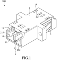
- Fig. 1 illustrates a perspective view of a fiber optical adapter according to an exemplary embodiment of the instant disclosure.
- Fig. 2 illustrates an exploded view of the fiber optical adapter of the exemplary embodiment.
- Figs. 3 and 4 illustrate schematic exploded view (1) and (2) showing the assembling of the fiber optical adapter of the exemplary embodiment.
- Fig. 5 illustrates a side sectional view showing the assembled optical fiber adapter of the exemplary embodiment.
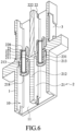
- Fig. 6 illustrates a top sectional view showing the assembled optical fiber adapter of the exemplary embodiment.
- the fiber optical adapter is provided for being inserted by several optical fiber connectors (not shown).
- the fiber optical connector may be a Lucent Connector (LC) connector used for high density connection application.
- the fiber optical adapter 100 comprises a base body 1 and a base element 2.
- the base body 1 comprises a receiving groove 10. Two ends of the base body 1 form insertion openings 11 respectively communicating with the receiving groove 10.
- the base element 2 is in the receiving groove 10 of the base body 1.
- the base element 2 comprises a first connection member 21, a second connection member 22, and a plurality of socket members 23.
- the first connection member 21 comprises a first main body 211, a first partition plate 212 protruding from one of two sides of the first main body 211, and a plurality of first sleeve members 213 at two sides of the first partition plate 212.
- the side of the first main body 211 comprises a plurality of first insertion holes 214 communicating with the first sleeve members 213, and the first partition plate 212 is in a portion of the receiving groove 10 at one of two ends of the base body 1.
- the second connection member 22 comprises a second main body 221 combined with the other side of the first main body 211, a second partition plate 222 protruding from one of two sides of the second main body 221, and a plurality of second sleeve members 223 at two sides of the second partition plate 222.
- the side of the second main body 221 forms a plurality of second insertion holes 224 respectively communicating with the second sleeve members 223, and the second partition plate 222 is in a portion of the receiving groove 10 at the other end of the base body 1.
- each of the socket members 23 Two ends of each of the socket members 23 are respectively inserted into the corresponding first insertion hole 214 and the corresponding second insertion hole 224, and the two ends of each of the socket members 23 are in the corresponding first sleeve member 213 and the corresponding second sleeve member 223.
- the base body 1 is combined with a buckle member 3 for fixing the base body 1 on the chassis.
- the base body 1 comprises a plurality of sliding slots 13 formed on an inner wall of the receiving groove 10.
- the sliding slots 13 are respectively located at the upper wall surface and the bottom wall surface of the middle portion in the receiving groove 10 in a longitudinal direction.
- the first connection member 21 comprises a plurality of first sliding rails 215 formed on an upper portion and a lower portion of the first partition plate 212.
- the second connection member 22 comprises a plurality of second sliding rails 225 formed on an upper portion and a lower portion of the second partition plate 222. Each of the first sliding rails 215 and each of the second sliding rails 225 are respectively engaged with the corresponding sliding slot 13.
- the second partition plate 222 comprises an engaging point 229 protruding from at least one of the second sliding rails 225, the base body 1 comprises an engaging groove 19 in at least one of the sliding slots 13, and the engaging point 229 is engaged with the engaging groove 19.
- the base element 2 comprises the first connection member 21 and the second connection member 22 adapted to be combined with each other.
- the first connection member 21 and the second connection member 22 are respectively of a T-shaped structure from a top view thereof, and the assembly of the first connection member 21 and the second connection member 22 is approximately of a cross structure.
- the first connection member 21 comprises a first protrusion 216 formed on the other side of the first main body 211
- the second connection member 22 comprises a second recessed hole 227 formed on the other side of the second main body 221
- the first protrusion 216 is engaged with the second recessed hole 227.
- the first connection member 21 comprises a first recessed hole 217 formed on the other side of the first main body 211
- the second connection member 22 comprises a second protrusion 226 formed on the other side of the second main body 221
- the second protrusion 226 is engaged with the first recessed hole 217.
- each of the socket members 23 is made of a ceramic material.
- each of the socket members 23 comprises a breakoff notch 231 extending in a longitudinal direction.
- a cross section of each of the socket members 23 forms a C-shape ring structure. Accordingly, when the core member of the fiber optical connector is inserted into the socket member 23 having the C-shape ring structure, the inner diameter of the core member can be expanded by the breakoff notch 231 of the socket member 23.
- each of the socket members 23 is an elongated tubular member, and a cross section of each of the socket members 23 forms a O-shape ring structure.
- the inner diameter of the socket member 23 having the O-shape ring structure is substantially greater than the inner diameter of the socket member 23 having the C-shape ring structure.
- a first annular wall 218 is protruding from each of the first sleeve members 213 and blocking an end portion of the corresponding socket member 23
- a second annular wall 228 is protruding from each of the second sleeve members 223 and blocking an end portion of the corresponding socket member 23.
- the socket member 23 is limited between the first sleeve member 213 and the second sleeve member 223.
- the base body 1 comprises a stopping block 15 formed on the inner wall of the receiving groove 10, the first main body 211 forms an engaging block 2115, and the stopping block 15 is abutted against the engaging block 2115.
- two ends of the base body 1 may comprise several insertion openings 11.
- the base body 1 may comprise four insertion openings 11, eight insertion openings 11, sixteen insertion openings 11, thirty two insertion openings 11, so that several optical fiber connectors can be inserted into the insertion openings 11.
- the base body 1 is a hollow shell, of a rectangular structure, and of a one-piece member, so that the base body 1 can have a firm structure.
- the base body is a one-piece member formed by injection molding and has an improved structural strength.
- the two main bodies of the two-piece type base body known to the inventor are combined with each other by welding.
- the two main bodies of the adapter may be combined with each other with an offset due to improper welding process.
- the two main bodies of the adapter are not tightly welded with each other so as to have a gap formed at the welded portion of the adapter. Under this arrangement, optical loss may occur easily and water moist may enter into the adapter easily when the adapter is in use.
- a welding machine has to be provided for the welding process.
- the adapter manufactured with the welding process would have a lower structural strength.
- problems occur to the two-piece type base body known to the inventor, such as, misalignment, improper sealing, having a gap between the two pieces, and lower structural strength for the combined base body, can be improved.
- the first connection member and the second connection member are manufactured with the same mold. After the first connection member and the second connection member are assembled with each other, the first connection member and the second connection member can be assembled into and fixed into the case body in a convenient manner, thereby improving the production and manufacturing of the adapter.
Landscapes
- Physics & Mathematics (AREA)
- General Physics & Mathematics (AREA)
- Optics & Photonics (AREA)
- Mechanical Coupling Of Light Guides (AREA)
- Light Guides In General And Applications Therefor (AREA)
- Optical Couplings Of Light Guides (AREA)
Description
- The instant disclosure relates to an adapter, and more particular to a fiber optical adapter.
- The optical fiber is an tool for optical transmission. In general, in a fiber optical connection device, two ends of a female adapter are inserted by male optical adapters, thereby achieving the fixation between the adapters of the fiber optical connection device and allowing data transmission between electronic devices.
- In general, a Lucent Connector (LC) type optical adapter is an optical transmission connector for connecting to the LC type optical transmission cable for optical signal transmission.
-
JP 3 220 604 UJP 2008 046146 A US 2014/072263 A1 . - In the configuration of an LC type optical adapter known to the inventor, the two main bodies (the casing) of the adapter are combined with each other by welding. As a result, the main bodies may be combined with each other with an offset due to improper welding process. Thus, when a stress is applied on the welded portion between the two main bodies, the welded portion may break easily. Moreover, in the manufacture of the adapter, a welding machine has to be provided for the welding process, thereby increasing the manufacturing cost of the adapter.
- According to the invention, a fiber optical adapter according to
claim 1 is provided. Moreover, some further fiber optical adapters are defined by the dependent claims. - According to one or some embodiments of the instant disclosure, problems occur to the two-piece type base body known to the inventor, such as, misalignment, improper sealing, having a gap between the two pieces, and lower structural strength for the combined base body, can be improved. According to one or some embodiments of the instant disclosure, the first connection member and the second connection member are manufactured with the same mold. After the first connection member and the second connection member are assembled with each other, the first connection member and the second connection member can be assembled into and fixed into the case body in a convenient manner, thereby improving the production and manufacturing of the adapter.
- The instant disclosure will become more fully understood from the detailed description given herein below for illustration only, and thus not limitative of the instant disclosure, wherein:
-
Fig. 1 illustrates a perspective view of a fiber optical adapter according to an exemplary embodiment of the instant disclosure; -
Fig. 2 illustrates an exploded view of the fiber optical adapter of the exemplary embodiment; -
Fig. 3 illustrates a schematic exploded view (1) showing the assembling of the fiber optical adapter of the exemplary embodiment; -
Fig. 4 illustrates a schematic exploded view (2) showing the assembling of the fiber optical adapter of the exemplary embodiment; -
Fig. 5 illustrates a side sectional view showing the assembled optical fiber adapter of the exemplary embodiment; and -
Fig. 6 illustrates a top sectional view showing the assembled optical fiber adapter of the exemplary embodiment. - Detailed description of the characteristics and the advantages of the instant disclosure are shown in the following embodiments. The technical content and the implementation of the instant disclosure should be readily apparent to any person skilled in the art from the detailed description, and the purposes and the advantages of the instant disclosure should be readily understood by any person skilled in the art with reference to content, claims, and drawings in the instant disclosure.
- Please refer to
Figs. 1 to 6 .Fig. 1 illustrates a perspective view of a fiber optical adapter according to an exemplary embodiment of the instant disclosure.Fig. 2 illustrates an exploded view of the fiber optical adapter of the exemplary embodiment.Figs. 3 and4 illustrate schematic exploded view (1) and (2) showing the assembling of the fiber optical adapter of the exemplary embodiment.Fig. 5 illustrates a side sectional view showing the assembled optical fiber adapter of the exemplary embodiment.Fig. 6 illustrates a top sectional view showing the assembled optical fiber adapter of the exemplary embodiment. - In this embodiment, the fiber optical adapter is provided for being inserted by several optical fiber connectors (not shown). The fiber optical connector may be a Lucent Connector (LC) connector used for high density connection application. The fiber
optical adapter 100 comprises abase body 1 and abase element 2. - According to the claimed invention, the
base body 1 comprises a receivinggroove 10. Two ends of thebase body 1form insertion openings 11 respectively communicating with the receivinggroove 10. - The
base element 2 is in thereceiving groove 10 of thebase body 1. Thebase element 2 comprises afirst connection member 21, asecond connection member 22, and a plurality ofsocket members 23. - The
first connection member 21 comprises a firstmain body 211, afirst partition plate 212 protruding from one of two sides of the firstmain body 211, and a plurality offirst sleeve members 213 at two sides of thefirst partition plate 212. The side of the firstmain body 211 comprises a plurality offirst insertion holes 214 communicating with thefirst sleeve members 213, and thefirst partition plate 212 is in a portion of thereceiving groove 10 at one of two ends of thebase body 1. - The
second connection member 22 comprises a secondmain body 221 combined with the other side of the firstmain body 211, asecond partition plate 222 protruding from one of two sides of the secondmain body 221, and a plurality ofsecond sleeve members 223 at two sides of thesecond partition plate 222. The side of the secondmain body 221 forms a plurality ofsecond insertion holes 224 respectively communicating with thesecond sleeve members 223, and thesecond partition plate 222 is in a portion of the receivinggroove 10 at the other end of thebase body 1. - Two ends of each of the
socket members 23 are respectively inserted into the correspondingfirst insertion hole 214 and the correspondingsecond insertion hole 224, and the two ends of each of thesocket members 23 are in the correspondingfirst sleeve member 213 and the correspondingsecond sleeve member 223. - In this embodiment, more specifically, the
base body 1 is combined with abuckle member 3 for fixing thebase body 1 on the chassis. - According to the claimed invention, the
base body 1 comprises a plurality of slidingslots 13 formed on an inner wall of thereceiving groove 10. Thesliding slots 13 are respectively located at the upper wall surface and the bottom wall surface of the middle portion in the receivinggroove 10 in a longitudinal direction. Thefirst connection member 21 comprises a plurality of first slidingrails 215 formed on an upper portion and a lower portion of thefirst partition plate 212. Thesecond connection member 22 comprises a plurality of second slidingrails 225 formed on an upper portion and a lower portion of thesecond partition plate 222. Each of the first slidingrails 215 and each of the second slidingrails 225 are respectively engaged with the correspondingsliding slot 13. - The
second partition plate 222 comprises anengaging point 229 protruding from at least one of the second slidingrails 225, thebase body 1 comprises anengaging groove 19 in at least one of thesliding slots 13, and theengaging point 229 is engaged with theengaging groove 19. After thefirst connection member 21 and thesecond connection member 22 are connected and fixed with each other, thefirst connection member 21 is aligned with and inserted into the insertion opening 11 at one of two ends of thebase body 1, so that thefirst connection member 21 and thesecond connection member 22 are slid into thereceiving groove 10 of thebase body 1 and theengaging point 229 is engaged with theengaging groove 19. Therefore, thesecond connection member 22 can be stably fixed in thebase body 1, and the assembling of the fiber optical adapter can be very convenient. - In this embodiment, more specifically, the
base element 2 comprises thefirst connection member 21 and thesecond connection member 22 adapted to be combined with each other. Thefirst connection member 21 and thesecond connection member 22 are respectively of a T-shaped structure from a top view thereof, and the assembly of thefirst connection member 21 and thesecond connection member 22 is approximately of a cross structure. According to the claimed invention, thefirst connection member 21 comprises a first protrusion 216 formed on the other side of the firstmain body 211, thesecond connection member 22 comprises a secondrecessed hole 227 formed on the other side of the secondmain body 221, and the first protrusion 216 is engaged with the secondrecessed hole 227. - In this embodiment, more specifically, the
first connection member 21 comprises a first recessed hole 217 formed on the other side of the firstmain body 211, thesecond connection member 22 comprises asecond protrusion 226 formed on the other side of the secondmain body 221, and thesecond protrusion 226 is engaged with the first recessed hole 217. - In this embodiment, more specifically, each of the
socket members 23 is made of a ceramic material. In this embodiment, each of thesocket members 23 comprises abreakoff notch 231 extending in a longitudinal direction. A cross section of each of thesocket members 23 forms a C-shape ring structure. Accordingly, when the core member of the fiber optical connector is inserted into thesocket member 23 having the C-shape ring structure, the inner diameter of the core member can be expanded by thebreakoff notch 231 of thesocket member 23. - In this embodiment, more specifically, each of the
socket members 23 is an elongated tubular member, and a cross section of each of thesocket members 23 forms a O-shape ring structure. The inner diameter of thesocket member 23 having the O-shape ring structure is substantially greater than the inner diameter of thesocket member 23 having the C-shape ring structure. - In this embodiment, more specifically, a first
annular wall 218 is protruding from each of thefirst sleeve members 213 and blocking an end portion of the correspondingsocket member 23, and a secondannular wall 228 is protruding from each of thesecond sleeve members 223 and blocking an end portion of the correspondingsocket member 23. Thesocket member 23 is limited between thefirst sleeve member 213 and thesecond sleeve member 223. - In this embodiment, more specifically, the
base body 1 comprises a stoppingblock 15 formed on the inner wall of the receivinggroove 10, the firstmain body 211 forms anengaging block 2115, and the stoppingblock 15 is abutted against the engagingblock 2115. - In this embodiment, more specifically, two ends of the
base body 1 may compriseseveral insertion openings 11. Thebase body 1 may comprise fourinsertion openings 11, eightinsertion openings 11, sixteeninsertion openings 11, thirty twoinsertion openings 11, so that several optical fiber connectors can be inserted into theinsertion openings 11. - In this embodiment, more specifically, the
base body 1 is a hollow shell, of a rectangular structure, and of a one-piece member, so that thebase body 1 can have a firm structure. The base body is a one-piece member formed by injection molding and has an improved structural strength. It is understood that, the two main bodies of the two-piece type base body known to the inventor are combined with each other by welding. As a result, the two main bodies of the adapter may be combined with each other with an offset due to improper welding process. Hence, the two main bodies of the adapter are not tightly welded with each other so as to have a gap formed at the welded portion of the adapter. Under this arrangement, optical loss may occur easily and water moist may enter into the adapter easily when the adapter is in use. Moreover, in the manufacture of the adapter, a welding machine has to be provided for the welding process. Furthermore, the adapter manufactured with the welding process would have a lower structural strength. - According to one or some embodiments of the instant disclosure, problems occur to the two-piece type base body known to the inventor, such as, misalignment, improper sealing, having a gap between the two pieces, and lower structural strength for the combined base body, can be improved. According to one or some embodiments of the instant disclosure, the first connection member and the second connection member are manufactured with the same mold. After the first connection member and the second connection member are assembled with each other, the first connection member and the second connection member can be assembled into and fixed into the case body in a convenient manner, thereby improving the production and manufacturing of the adapter.
- While the instant disclosure has been described by the way of example and in terms of the preferred embodiments, it is to be understood that the invention need not be limited to the disclosed embodiments. On the contrary, it is intended to cover various modifications and similar arrangements included within the scope of the appended claims, the scope of which should be accorded the broadest interpretation so as to encompass all such modifications and similar structures.
Claims (7)
- A fiber optical adapter (100), comprising:a base body (1), comprising a receiving groove (10), wherein two ends of the base body (1) form insertion openings (11) respectively communicating with the receiving groove (10); anda base element (2) in the receiving groove (10) of the base body (1), wherein the base element (2) comprises:a first connection member (21), comprising a first main body (211), a first partition plate (212) protruding from one of two sides of the first main body (211), and a plurality of first sleeve members (213) at two sides of the first partition plate (212), wherein the side of the first main body (211) forms a plurality of first insertion holes (214) respectively communicating with the first sleeve members (213), and the first partition plate (212) is in a portion of the receiving groove (10) at one of two ends of the base body (1);a second connection member (22), comprising a second main body (221) combined with the other side of the first main body (211), a second partition plate (222) protruding from one of two sides of the second main body (211), and a plurality of second sleeve members (223) at two sides of the second partition plate (222), wherein the side of the second main body (221) forms a plurality of second insertion holes (224) respectively communicating with the second sleeve members (223), and the second partition plate (222) is in a portion of the receiving groove (10) at the other end of the base body (1); anda plurality of socket members (23), wherein two ends of each of the socket members (23) are respectively inserted into the corresponding first insertion hole (214) and the corresponding second insertion hole (224), and the two ends of each of the socket members (23) are in the corresponding first sleeve member (213) and the corresponding second sleeve member (223);wherein the base body (1) comprises a plurality of sliding slots (13) formed on an inner wall of the receiving groove (10), the first connection member (21) comprises a plurality of first sliding rails (215) formed on an upper portion and a lower portion of the first partition plate (212), the second connection member (22) comprises a plurality of second sliding rails (225) formed on an upper portion and a lower portion of the second partition plate (222), and each of the first sliding rails (215) and each of the second sliding rails (225) are respectively engaged with the corresponding sliding slot (13);wherein the second partition plate (222) comprises an engaging point (229) protruding from at least one of the second sliding rails (225), the base body (1) comprises an engaging groove (19) in at least one of the sliding slots (13), and the engaging point (229) is engaged with the engaging groove (19);wherein the first connection member (21) comprises a first protrusion (216) formed on the other side of the first main body (211), the second connection member (22) comprises a second recessed hole (227) formed on the other side of the second main body (221), and the first protrusion (216) is engaged with the second recessed hole (227).
- The fiber optical adapter (100) according to claim 1, wherein the first connection member (21) comprises a first recessed hole (217) formed on the other side of the first main body (211), the second connection member (22) comprises a second protrusion (226) formed on the other side of the second main body (221), and the second protrusion (226) is engaged with the first recessed hole (217).
- The fiber optical adapter (100) according to claim 1, wherein each of the socket members (23) comprises a breakoff notch (231) extending in a longitudinal direction, and a cross section of each of the socket members (23) forms a C-shape ring structure.
- The fiber optical adapter (100) according to claim 1, wherein each of the socket members (23) is an elongated tubular member, and a cross section of each of the socket members forms a O-shape ring structure.
- The fiber optical adapter (100) according to claim 1, wherein a first annular wall (218) is protruding from each of the first sleeve members (213) and blocking an end portion of the corresponding socket member (23).
- The fiber optical adapter (100) according to claim 1, wherein a second annular wall (228) is protruding from each of the second sleeve members (223) and blocking an end portion of the corresponding socket member (23).
- The fiber optical adapter (100) according to claim 1, wherein the base body (1) comprises a stopping block (15) formed on an inner wall of the receiving groove (10), the first main body (211) forms an engaging block (2115), and the stopping block (15) is abutted against the engaging block (2115).
Applications Claiming Priority (1)
| Application Number | Priority Date | Filing Date | Title |
|---|---|---|---|
| TW108207544U TWM584433U (en) | 2019-06-13 | 2019-06-13 | Fiber adapter |
Publications (3)
| Publication Number | Publication Date |
|---|---|
| EP3751321A1 EP3751321A1 (en) | 2020-12-16 |
| EP3751321B1 true EP3751321B1 (en) | 2024-11-06 |
| EP3751321C0 EP3751321C0 (en) | 2024-11-06 |
Family
ID=69052647
Family Applications (1)
| Application Number | Title | Priority Date | Filing Date |
|---|---|---|---|
| EP20179670.3A Active EP3751321B1 (en) | 2019-06-13 | 2020-06-12 | Fiber optical adapter |
Country Status (7)
| Country | Link |
|---|---|
| US (1) | US11022758B2 (en) |
| EP (1) | EP3751321B1 (en) |
| JP (1) | JP3227756U (en) |
| CN (1) | CN212301975U (en) |
| ES (1) | ES2993553T3 (en) |
| PL (1) | PL3751321T3 (en) |
| TW (1) | TWM584433U (en) |
Families Citing this family (4)
| Publication number | Priority date | Publication date | Assignee | Title |
|---|---|---|---|---|
| TWM584433U (en) * | 2019-06-13 | 2019-10-01 | 連訊通信股份有限公司 | Fiber adapter |
| USD936588S1 (en) * | 2019-10-09 | 2021-11-23 | Foci Fiber Optic Communications, Inc. | Optical fibers split connectors housing |
| CN216083178U (en) * | 2021-05-31 | 2022-03-18 | 连讯通信(天津)有限公司 | Fiber Connector Assemblies |
| JP1732289S (en) * | 2022-05-10 | 2022-12-15 | electrical connector |
Family Cites Families (13)
| Publication number | Priority date | Publication date | Assignee | Title |
|---|---|---|---|---|
| US6692159B2 (en) * | 2001-04-14 | 2004-02-17 | E20 Communications, Inc. | De-latching mechanisms for fiber optic modules |
| US7118281B2 (en) * | 2002-08-09 | 2006-10-10 | Jds Uniphase Corporation | Retention and release mechanisms for fiber optic modules |
| JP2008046146A (en) * | 2006-08-10 | 2008-02-28 | Sanwa Denki Kogyo Co Ltd | Adapter for optical connector interconnection |
| US7785018B2 (en) * | 2008-08-29 | 2010-08-31 | Corning Cable Systems Llc | Fiber optic adapters with integrated shutter |
| US9494746B2 (en) * | 2011-11-10 | 2016-11-15 | Panduit Corp. | Shuttered LC adapter |
| US20140072263A1 (en) * | 2012-09-10 | 2014-03-13 | Alliance Fiber Optic Products, Inc. | Optical fiber adapter having vertical wings |
| JP6038666B2 (en) * | 2013-01-21 | 2016-12-07 | 三和電気工業株式会社 | LC type optical connector interconnection adapter |
| JP6400892B2 (en) * | 2013-09-17 | 2018-10-03 | 三和電気工業株式会社 | LC type optical connector adapter with built-in dustproof shutter |
| CN107065259A (en) * | 2017-03-14 | 2017-08-18 | 惠科股份有限公司 | Display panel and display device |
| CN207623573U (en) * | 2017-12-06 | 2018-07-17 | 连展科技(天津)有限公司 | Fiber adapter |
| TWM561217U (en) * | 2018-01-09 | 2018-06-01 | Advanced Connectek Inc | Fiber adapter |
| CN208270800U (en) * | 2018-06-22 | 2018-12-21 | 清远市亿源通光电科技有限公司 | A kind of fiber adapter |
| TWM584433U (en) * | 2019-06-13 | 2019-10-01 | 連訊通信股份有限公司 | Fiber adapter |
-
2019
- 2019-06-13 TW TW108207544U patent/TWM584433U/en unknown
-
2020
- 2020-06-02 CN CN202020974066.1U patent/CN212301975U/en active Active
- 2020-06-10 JP JP2020002241U patent/JP3227756U/en active Active
- 2020-06-11 US US16/946,242 patent/US11022758B2/en active Active
- 2020-06-12 EP EP20179670.3A patent/EP3751321B1/en active Active
- 2020-06-12 ES ES20179670T patent/ES2993553T3/en active Active
- 2020-06-12 PL PL20179670.3T patent/PL3751321T3/en unknown
Also Published As
| Publication number | Publication date |
|---|---|
| JP3227756U (en) | 2020-09-17 |
| ES2993553T3 (en) | 2025-01-02 |
| US11022758B2 (en) | 2021-06-01 |
| CN212301975U (en) | 2021-01-05 |
| EP3751321A1 (en) | 2020-12-16 |
| EP3751321C0 (en) | 2024-11-06 |
| PL3751321T3 (en) | 2025-03-10 |
| TWM584433U (en) | 2019-10-01 |
| US20200393625A1 (en) | 2020-12-17 |
Similar Documents
| Publication | Publication Date | Title |
|---|---|---|
| US11022758B2 (en) | Fiber optical adapter having a railed partitioning | |
| US20160359258A1 (en) | Retaining Block and Modular Plug Insert | |
| EP4084233A1 (en) | Terminal position assurance and corresponding connector assembly | |
| CN111919344B (en) | RF connector including a flat center contact forked at the end to receive contact pins of a complementary connector and a solid insulating structure configured to guide the contact pins | |
| US6758603B2 (en) | Optical connector assembly | |
| EP0718651A2 (en) | Closed alignment sleeve for optical connectors | |
| US11016249B2 (en) | Fiber optical connector | |
| US5800199A (en) | Connector alignment guide | |
| KR830003030Y1 (en) | Connector | |
| US5730624A (en) | Secondary contact lock arrangement | |
| JP4768539B2 (en) | Adapter for interconnecting optical fiber connectors | |
| US7413449B1 (en) | Pluggable insulated terminal block | |
| CN100451707C (en) | A connecting apparatus for optical fibre | |
| CN200986602Y (en) | Optical fibre connecting device | |
| KR101802738B1 (en) | Connector of an optical cable for junction box | |
| US12494605B2 (en) | Connector and connector assembly | |
| US20260036756A1 (en) | Optical-fiber adapter | |
| US7281858B2 (en) | Optical connector which can be assembled without using screw parts | |
| US6712521B1 (en) | Optical connector enabling multicore structure by efficiently utilizing space | |
| US20230400640A1 (en) | Combinable optical-fiber adapter assembly | |
| KR102168404B1 (en) | Coaxial cable connector | |
| CN221225085U (en) | Integrated LC optical fiber adapter | |
| US20250105557A1 (en) | Connector housing assembly, connector and connector assembly | |
| KR20240015972A (en) | Terminal position assurance and connector having same | |
| US20200200980A1 (en) | Optical connector |
Legal Events
| Date | Code | Title | Description |
|---|---|---|---|
| PUAI | Public reference made under article 153(3) epc to a published international application that has entered the european phase |
Free format text: ORIGINAL CODE: 0009012 |
|
| STAA | Information on the status of an ep patent application or granted ep patent |
Free format text: STATUS: THE APPLICATION HAS BEEN PUBLISHED |
|
| AK | Designated contracting states |
Kind code of ref document: A1 Designated state(s): AL AT BE BG CH CY CZ DE DK EE ES FI FR GB GR HR HU IE IS IT LI LT LU LV MC MK MT NL NO PL PT RO RS SE SI SK SM TR |
|
| AX | Request for extension of the european patent |
Extension state: BA ME |
|
| STAA | Information on the status of an ep patent application or granted ep patent |
Free format text: STATUS: REQUEST FOR EXAMINATION WAS MADE |
|
| 17P | Request for examination filed |
Effective date: 20210616 |
|
| RBV | Designated contracting states (corrected) |
Designated state(s): AL AT BE BG CH CY CZ DE DK EE ES FI FR GB GR HR HU IE IS IT LI LT LU LV MC MK MT NL NO PL PT RO RS SE SI SK SM TR |
|
| RIN1 | Information on inventor provided before grant (corrected) |
Inventor name: CHIU, CHIN-HUANG |
|
| STAA | Information on the status of an ep patent application or granted ep patent |
Free format text: STATUS: EXAMINATION IS IN PROGRESS |
|
| 17Q | First examination report despatched |
Effective date: 20211213 |
|
| GRAP | Despatch of communication of intention to grant a patent |
Free format text: ORIGINAL CODE: EPIDOSNIGR1 |
|
| STAA | Information on the status of an ep patent application or granted ep patent |
Free format text: STATUS: GRANT OF PATENT IS INTENDED |
|
| INTG | Intention to grant announced |
Effective date: 20240703 |
|
| GRAS | Grant fee paid |
Free format text: ORIGINAL CODE: EPIDOSNIGR3 |
|
| GRAA | (expected) grant |
Free format text: ORIGINAL CODE: 0009210 |
|
| STAA | Information on the status of an ep patent application or granted ep patent |
Free format text: STATUS: THE PATENT HAS BEEN GRANTED |
|
| AK | Designated contracting states |
Kind code of ref document: B1 Designated state(s): AL AT BE BG CH CY CZ DE DK EE ES FI FR GB GR HR HU IE IS IT LI LT LU LV MC MK MT NL NO PL PT RO RS SE SI SK SM TR |
|
| REG | Reference to a national code |
Ref country code: GB Ref legal event code: FG4D |
|
| REG | Reference to a national code |
Ref country code: CH Ref legal event code: EP |
|
| REG | Reference to a national code |
Ref country code: DE Ref legal event code: R096 Ref document number: 602020040679 Country of ref document: DE |
|
| REG | Reference to a national code |
Ref country code: IE Ref legal event code: FG4D |
|
| U01 | Request for unitary effect filed |
Effective date: 20241111 |
|
| U07 | Unitary effect registered |
Designated state(s): AT BE BG DE DK EE FI FR IT LT LU LV MT NL PT RO SE SI Effective date: 20241119 |
|
| REG | Reference to a national code |
Ref country code: ES Ref legal event code: FG2A Ref document number: 2993553 Country of ref document: ES Kind code of ref document: T3 Effective date: 20250102 |
|
| PG25 | Lapsed in a contracting state [announced via postgrant information from national office to epo] |
Ref country code: HR Free format text: LAPSE BECAUSE OF FAILURE TO SUBMIT A TRANSLATION OF THE DESCRIPTION OR TO PAY THE FEE WITHIN THE PRESCRIBED TIME-LIMIT Effective date: 20241106 Ref country code: IS Free format text: LAPSE BECAUSE OF FAILURE TO SUBMIT A TRANSLATION OF THE DESCRIPTION OR TO PAY THE FEE WITHIN THE PRESCRIBED TIME-LIMIT Effective date: 20250306 |
|
| PG25 | Lapsed in a contracting state [announced via postgrant information from national office to epo] |
Ref country code: NO Free format text: LAPSE BECAUSE OF FAILURE TO SUBMIT A TRANSLATION OF THE DESCRIPTION OR TO PAY THE FEE WITHIN THE PRESCRIBED TIME-LIMIT Effective date: 20250206 |
|
| PG25 | Lapsed in a contracting state [announced via postgrant information from national office to epo] |
Ref country code: GR Free format text: LAPSE BECAUSE OF FAILURE TO SUBMIT A TRANSLATION OF THE DESCRIPTION OR TO PAY THE FEE WITHIN THE PRESCRIBED TIME-LIMIT Effective date: 20250207 |
|
| PG25 | Lapsed in a contracting state [announced via postgrant information from national office to epo] |
Ref country code: RS Free format text: LAPSE BECAUSE OF FAILURE TO SUBMIT A TRANSLATION OF THE DESCRIPTION OR TO PAY THE FEE WITHIN THE PRESCRIBED TIME-LIMIT Effective date: 20250206 |
|
| U20 | Renewal fee for the european patent with unitary effect paid |
Year of fee payment: 6 Effective date: 20250519 |
|
| PG25 | Lapsed in a contracting state [announced via postgrant information from national office to epo] |
Ref country code: SM Free format text: LAPSE BECAUSE OF FAILURE TO SUBMIT A TRANSLATION OF THE DESCRIPTION OR TO PAY THE FEE WITHIN THE PRESCRIBED TIME-LIMIT Effective date: 20241106 |
|
| PGFP | Annual fee paid to national office [announced via postgrant information from national office to epo] |
Ref country code: PL Payment date: 20250605 Year of fee payment: 6 |
|
| PGFP | Annual fee paid to national office [announced via postgrant information from national office to epo] |
Ref country code: GB Payment date: 20250620 Year of fee payment: 6 |
|
| PG25 | Lapsed in a contracting state [announced via postgrant information from national office to epo] |
Ref country code: SK Free format text: LAPSE BECAUSE OF FAILURE TO SUBMIT A TRANSLATION OF THE DESCRIPTION OR TO PAY THE FEE WITHIN THE PRESCRIBED TIME-LIMIT Effective date: 20241106 |
|
| PGFP | Annual fee paid to national office [announced via postgrant information from national office to epo] |
Ref country code: TR Payment date: 20250611 Year of fee payment: 6 |
|
| PGFP | Annual fee paid to national office [announced via postgrant information from national office to epo] |
Ref country code: CZ Payment date: 20250530 Year of fee payment: 6 |
|
| PLBE | No opposition filed within time limit |
Free format text: ORIGINAL CODE: 0009261 |
|
| STAA | Information on the status of an ep patent application or granted ep patent |
Free format text: STATUS: NO OPPOSITION FILED WITHIN TIME LIMIT |
|
| PGFP | Annual fee paid to national office [announced via postgrant information from national office to epo] |
Ref country code: ES Payment date: 20250718 Year of fee payment: 6 |
|
| 26N | No opposition filed |
Effective date: 20250807 |
|
| PGFP | Annual fee paid to national office [announced via postgrant information from national office to epo] |
Ref country code: CH Payment date: 20250701 Year of fee payment: 6 |
|
| PG25 | Lapsed in a contracting state [announced via postgrant information from national office to epo] |
Ref country code: MC Free format text: LAPSE BECAUSE OF FAILURE TO SUBMIT A TRANSLATION OF THE DESCRIPTION OR TO PAY THE FEE WITHIN THE PRESCRIBED TIME-LIMIT Effective date: 20241106 |
|
| PG25 | Lapsed in a contracting state [announced via postgrant information from national office to epo] |
Ref country code: IE Free format text: LAPSE BECAUSE OF NON-PAYMENT OF DUE FEES Effective date: 20250612 |
|
| U20 | Renewal fee for the european patent with unitary effect paid |
Year of fee payment: 7 Effective date: 20260401 |