EP3751294A1 - Device and method for synchronization of sensors - Google Patents
Device and method for synchronization of sensors Download PDFInfo
- Publication number
- EP3751294A1 EP3751294A1 EP19180186.9A EP19180186A EP3751294A1 EP 3751294 A1 EP3751294 A1 EP 3751294A1 EP 19180186 A EP19180186 A EP 19180186A EP 3751294 A1 EP3751294 A1 EP 3751294A1
- Authority
- EP
- European Patent Office
- Prior art keywords
- graphic representation
- signal
- transformation
- sensor
- combined
- Prior art date
- Legal status (The legal status is an assumption and is not a legal conclusion. Google has not performed a legal analysis and makes no representation as to the accuracy of the status listed.)
- Granted
Links
Images



Classifications
-
- G—PHYSICS
- G01—MEASURING; TESTING
- G01R—MEASURING ELECTRIC VARIABLES; MEASURING MAGNETIC VARIABLES
- G01R13/00—Arrangements for displaying electric variables or waveforms
- G01R13/02—Arrangements for displaying electric variables or waveforms for displaying measured electric variables in digital form
- G01R13/0218—Circuits therefor
- G01R13/0254—Circuits therefor for triggering, synchronisation
-
- H—ELECTRICITY
- H04—ELECTRIC COMMUNICATION TECHNIQUE
- H04Q—SELECTING
- H04Q9/00—Arrangements in telecontrol or telemetry systems for selectively calling a substation from a main station, in which substation desired apparatus is selected for applying a control signal thereto or for obtaining measured values therefrom
-
- H—ELECTRICITY
- H04—ELECTRIC COMMUNICATION TECHNIQUE
- H04Q—SELECTING
- H04Q2209/00—Arrangements in telecontrol or telemetry systems
- H04Q2209/80—Arrangements in the sub-station, i.e. sensing device
- H04Q2209/84—Measuring functions
- H04Q2209/845—Measuring functions where the measuring is synchronized between sensing devices
Definitions
- the invention relates to synchronization of sensors, in particular based on image registration. More specifically, the synchronization is based on aligning of graphic representations of signals obtained by at least two sensors.
- a measurement device that comprises a sensor e.g. is a signal analyzer or spectrum analyzer.
- the recorded signals are merged based on time-frequency windows of detections, which requires time-consuming synchronization of the used sensors. Also, a separate synchronization signal for synchronizing the sensors is required.
- US 7,624,294 B2 e.g. discloses how to synchronize measurement devices using additional trigger signals. These approaches however result in high manufacturing and operating costs of measurement devices.
- the object of the invention is to provide a device for synchronization of at least two sensors with reduced manufacturing and operating costs. Moreover, the object is to provide an according method and computer program.
- An inventive device for synchronization of at least two sensors is configured to: generate a first graphic representation of a first signal obtained by a first sensor of the device; generate a second graphic representation of a second signal obtained by a second sensor of the device; and apply a transformation to the second graphic representation to align the second graphic representation and the first graphic representation and to obtain a combined graphic representation.
- the first sensor and/or the second sensor is a device capable of receiving a physical event or unit (e.g. temperature, pressure, velocity, distance, radio frequency, current, voltage, light, radiation).
- a physical event or unit e.g. temperature, pressure, velocity, distance, radio frequency, current, voltage, light, radiation.
- the first sensor and the second sensor obtain signals at different locations.
- the obtaining of the signals with the sensors is not time synchronized based on a synchronization signal. That is, the sensors are not time-synchronized based on an additional signal. Synchronization is obtained based on the graphic representations of the first and second signal.
- the first sensor and the second sensor are located in separate physical units, which together form the device.
- the separate units can be connected by means of a communication link.
- the device is further configured to determine a time offset between the first signal and the second signal based on the first graphic representation, the second graphic representation and the combined graphic representation, and to synchronize the first sensor and the second sensor based on the time offset.
- the time offset is also determined based on a parameter of the transformation.
- the synchronization is time-synchronization.
- the time synchronization is obtained based on a visual content of the first graphic representation, the second graphic representation and the combined graphic representation.
- the time offset is determined based on a time stamp which relates to an image line of at least one of the graphic representations (i.e. the first graphic representation, the second graphic representation and/or the combined graphic representation).
- the device is further configured to generate a synchronized signal based on the first signal, the second signal and the time offset. This is beneficial, as a more versatile device is provided, which can not only synchronize the sensors, but also generate and output a synchronized signal.
- the synchronized signal is a time-synchronized signal.
- the synchronized signal is called a fused signal, e.g. obtained from signal fusion.
- the first signal is a radio frequency, RF, signal
- the second signal is a RF signal.
- the inventive device can be used in a RF measurement device such as a spectrum analyzer.
- the first sensor and/or the second sensor is a RF sensor, e.g. an antenna.
- the device is further configured to align the second graphic representation and the first graphic representation based on an image registration algorithm, in particular based on an intensity-based and/or feature-based image registration algorithm and/or a neural network. This allows for an efficient and effective way of aligning the graphic representations.
- the first graphic representation and/or the second graphic representation and/or the combined graphic representation is a frequency over time diagram, a spectrum, or a water fall spectrum.
- the inventive device can be used in a device which generates or processes a frequency over time diagram, a spectrum, or a water fall spectrum (e.g. a spectrum analyzer).
- these kind of graphic representations typically contain a lot of parallel patterns, they can be transformed and aligned very efficiently.
- the first graphic representation and/or the second graphic representation illustrates a sampled signal including signal values and time stamps of the signal values.
- the transformation includes at least one of the following: rotation, scaling, translation, linear transformation, affine transformation, rigid transformation, non-rigid transformation, Euclidean transformation, similarity transformation, projective transformation, transformation based on a radial basis function, transformation based on a physical continuum model, transformation based on a large deformation model. This allows for using various efficient and effective ways of transforming the graphic representations.
- the device is further configured to apply a plausibility check to the combined graphic representation. This ensures that an operating result of the inventive device is reliable, as a further check is applied.
- applying the plausibility check to the combined graphic representation includes determining, whether all sensors receive common data, or a subset of common data; and/or to determine, whether the received signals are theoretically possible; and/or to determine, whether one of the sensors or the device is malfunctioning.
- the device is further configured to output, post process, and/or store the combined graphic representation. This allows for a versatile use of the device.
- the combined graphic representation can be graphically output.
- post processing includes magnitude alignment.
- the combined graphic representation can be stored on a storage medium, e.g. for post processing.
- An inventive method for synchronization of at least two sensors comprises the steps of generating, by a device, a first graphic representation of a first signal obtained by a first sensor of the device; generating, by the device, a second graphic representation of a second signal obtained by a second sensor of the device; applying, by the device, a transformation to the second graphic representation to align the second graphic representation and the first graphic representation and to obtain a combined graphic representation.
- the method further comprises determining, by the device, a time offset between the first signal and the second signal based on the first graphic representation, the second graphic representation and the combined graphic representation, and synchronizing, by the device, the first sensor and the second sensor based on the time offset.
- the method further comprises generating, by the device, a synchronized signal based on the first signal, the second signal and the time offset.
- the first signal is a radio frequency, RF, signal
- the second signal is a RF signal
- the method further comprises aligning the second graphic representation and the first graphic representation based on an image registration algorithm, in particular based on an intensity-based and/or feature-based image registration algorithm and/or a neural network.
- the first graphic representation and/or the second graphic representation and/or the combined graphic representation is a frequency over time diagram, a spectrum, or a water fall spectrum.
- the transformation includes at least one of the following: rotation, scaling, translation, linear transformation, affine transformation, rigid transformation, non-rigid transformation, Euclidean transformation, similarity transformation, projective transformation, transformation based on a radial basis function, transformation based on a physical continuum model, transformation based on a large deformation model.
- the method further comprises applying a plausibility check to the combined graphic representation.
- the method further comprises outputting, post processing, and/or storing the combined graphic representation.
- the inventive method comprises the same advantages as the inventive device.
- An inventive computer program comprises program code for performing the previously described method, when the computer program runs on a computer or a digital signal processor.
- the inventive computer program comprises the same advantages as the inventive device.
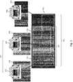
- FIG. 1 shows a device 100 for synchronization of at least two sensors 101, 102.
- the device 100 e.g. is a measurement device such as a signal analyzer or a spectrum analyzer.
- the device 100 includes a first sensor 101 and a second sensor 102.
- a first signal 103 is obtained by the first sensor 101
- a second signal 104 is obtained by the second sensor 102.
- the device 100 is further configured to generate a first graphic representation 105 of the first signal 103, and a second graphic representation 106 of the second signal 104.
- the device 100 is further configured to apply a transformation to the second graphic representation 106 to align the second graphic representation 106 and the first graphic representation 105 and to obtain a combined graphic representation 107.
- the combined graphic representation 107 is obtained by matching patterns of the first graphic representation 105 with corresponding patterns (which are similar or identical) of the second graphic representation 106. As shown in FIG. 1 , the right pattern of the first graphic representation 105 matches the left pattern of the second graphic representation 106. A transformation is applied to the second graphic representation 106, to align (i.e. to overlay) said patterns and obtain the combined graphic representation 107.
- the device 100 can synchronize the first sensor 101 and the second sensor 102.
- FIG. 2 shows the device 100 in more detail.
- the device 100 described in FIG. 2 includes all features and functionality of the device 100 of FIG. 1 . Therefore, corresponding features are labeled by identical reference signs.
- the device 100 optionally is further configured to determine a time offset 201 between the first signal 103 and the second signal 104. The determination is based on the first graphic representation 105, the second graphic representation 106 and the combined graphic representation 107. Once the time offset is determined, the device 100 synchronizes the first sensor 101 and the second sensor 102 based on the time offset 201.
- each image line of a graphic representation can be associated with a time stamp.
- a first image line with a first time stamp 202 is shown
- a second image line with a second time stamp 203 is shown in the second graphic representation 106.
- the first and the second image line at least partially have a common pattern. That is, the time offset 201 e.g. can be calculated by aligning the graphic representations and by subtracting the time stamp 203 from the time stamp 202 (or by subtracting the time stamp 202 from the time stamp 203, depending on a use case).
- the device 100 based on the first signal 103, the second signal 104 and the time offset 201, the device 100 optionally can generate a synchronized signal 204 and output it.
- the synchronized signal may also be called fused signal.
- FIG. 3 shows an operating scenario in which the device 100 is used.
- the device 100 is formed by at least two measurement devices.
- these measurement devices can be signal and/or spectrum analyzers.
- the first sensor 101 is comprised by the first measurement device and the second sensor 102 is comprised by the second measurement device.
- a third measurement device can be comprised by the device 100.
- a third sensor 301 (which obtains a third signal) is included in the third measurement device.
- the device 100 can optionally be configured to generate a third graphic representation 302 based on the third signal.
- the third graphic representation 302 can then also be transformed and included in a combined graphic representation 303 (which also comprises the combined graphic representation 107) and can be used for synchronization of the three sensors 101, 102, 301, and/or for calculating the time offset 201.
- the first graphic representation 105 and/or the second graphic representation 106 and/or the combined graphic representation 107 or 303 can be a frequency over time diagram, a spectrum, or a water fall spectrum (this can also be the case for the device 100 of FIG. 1 or FIG. 2 ).
- These kinds of representations are in particular obtained, if the first signal 103 is a RF signal, and/or if the second signal 104 is a RF signal.
- the sensors and the measurement devices can be connected using a communication link.
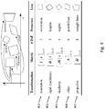
- FIG. 4 shows example transformations which can be implemented by the device 100 according to any one of FIG. 1 to 3 above.
- a translation 401 a rigid / Euclidean transformation 402, a similarity transformation 403, an affine transformation 404, or a projective transformation 405 can be used.
- the device 100 is however not limited to these translations, that is, also a rotation, a scaling, a linear transformation, a non-rigid transformation, a transformation based on a radial basis function, a transformation based on a physical continuum model, and/or a transformation based on a large deformation model can be used.
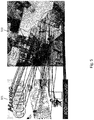
- FIG. 5 shows a schematic example of image registration that can be implemented by the device 100. More specifically, aligning the second graphic representation 106 and the first graphic representation 105 can optionally be based on an intensity-based and/or feature-based image registration algorithm. Intensity-based methods compare intensity patterns in images via correlation metrics, while feature-based methods determine the correspondence between image features such as points, lines, and contours. In FIG. 5 , the correspondence of features in the left graphic representation 501 and the right graphic representation 502is indicated by black lines.
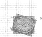
- FIG. 6 shows another schematic example of image registration.
- Alignment algorithms the can be implemented by the device 100 can be mathematical functions or neuronal networks e.g. as used in medical imaging (e.g. computer tomography) for aligning pictures 601, 602 of different sectors (e.g. while a patient to be examined is slightly moving so that taken pictures cannot be superimposed without alignment).
- medical imaging e.g. computer tomography
- FIG. 7 schematically shows a method 700 according to an embodiment of the present invention.
- the method is for synchronization of at least two sensors 101, 102 and comprises a first step of generating 701, by a device 100, a first graphic representation 105 of a first signal 103 obtained by a first sensor 101 of the device 100.
- the method 700 comprises a second step of generating 702, by the device 100, a second graphic representation 106 of a second signal 104 obtained by a second sensor 102 of the device 100.
- the method comprises a third step of applying 703, by the device 100, a transformation to the second graphic representation 106 to align the second graphic representation 106 and the first graphic representation 105 and to obtain a combined graphic representation 107.
- graphic representations (resulting from data of different sensors) can be aligned graphically to a seamless picture and at the same time the graphical representations are timely synchronized via its visual content (not by using an additional synchronization signal or mechanism) in order to obtain a useful result.
- This is possible because timing information is contained in the (visual) representation of the signal.
- Each line of the graphical representation can have a time stamp obtained during sampling.
- the invention is not limited by the examples.
- the characteristics of the exemplary embodiments can be used in any advantageous combination.
Landscapes
- Physics & Mathematics (AREA)
- General Physics & Mathematics (AREA)
- Engineering & Computer Science (AREA)
- Computer Networks & Wireless Communication (AREA)
- Image Analysis (AREA)
Abstract
Description
- The invention relates to synchronization of sensors, in particular based on image registration. More specifically, the synchronization is based on aligning of graphic representations of signals obtained by at least two sensors.
- It is a typical scenario that a user records signals using different sensors and then wants to merge the obtained signals. The sensors are for example located in a single device or are distributed across multiple devices. A measurement device that comprises a sensor e.g. is a signal analyzer or spectrum analyzer.
- The recorded signals are merged based on time-frequency windows of detections, which requires time-consuming synchronization of the used sensors. Also, a separate synchronization signal for synchronizing the sensors is required.
US 7,624,294 B2 e.g. discloses how to synchronize measurement devices using additional trigger signals. These approaches however result in high manufacturing and operating costs of measurement devices. - The object of the invention is to provide a device for synchronization of at least two sensors with reduced manufacturing and operating costs. Moreover, the object is to provide an according method and computer program.
- The object is solved by the features of the first independent claim for the device and by the features of the second independent claim for the method. Further, it is solved by the features of an associated computer program claim. The dependent claims contain further developments.
- An inventive device for synchronization of at least two sensors is configured to: generate a first graphic representation of a first signal obtained by a first sensor of the device; generate a second graphic representation of a second signal obtained by a second sensor of the device; and apply a transformation to the second graphic representation to align the second graphic representation and the first graphic representation and to obtain a combined graphic representation.
- This allows for cost effective manufacturing and operating of the device, wherein synchronization of the sensors is enabled without using an additional synchronization signal.
- In particular, the first sensor and/or the second sensor is a device capable of receiving a physical event or unit (e.g. temperature, pressure, velocity, distance, radio frequency, current, voltage, light, radiation).
- In particular, the first sensor and the second sensor obtain signals at different locations.
- In particular, the obtaining of the signals with the sensors is not time synchronized based on a synchronization signal. That is, the sensors are not time-synchronized based on an additional signal. Synchronization is obtained based on the graphic representations of the first and second signal.
- In particular, the first sensor and the second sensor are located in separate physical units, which together form the device. To this end, the separate units can be connected by means of a communication link.
- Advantageously and preferably, the device is further configured to determine a time offset between the first signal and the second signal based on the first graphic representation, the second graphic representation and the combined graphic representation, and to synchronize the first sensor and the second sensor based on the time offset.
- This allows for synchronization of the sensors based on the time offset. As the time offset is generated based on the graphic representations, synchronization can be performed without an additional synchronization signal.
- In particular, the time offset is also determined based on a parameter of the transformation. In particular, the synchronization is time-synchronization. In particular, the time synchronization is obtained based on a visual content of the first graphic representation, the second graphic representation and the combined graphic representation.
- This is beneficial as the time synchronization can be obtained without using an additional synchronization signal or mechanism.
- In particular, the time offset is determined based on a time stamp which relates to an image line of at least one of the graphic representations (i.e. the first graphic representation, the second graphic representation and/or the combined graphic representation).
- Advantageously and preferably, the device is further configured to generate a synchronized signal based on the first signal, the second signal and the time offset. This is beneficial, as a more versatile device is provided, which can not only synchronize the sensors, but also generate and output a synchronized signal.
- In particular, the synchronized signal is a time-synchronized signal. In particular, the synchronized signal is called a fused signal, e.g. obtained from signal fusion.
- Advantageously and preferably, the first signal is a radio frequency, RF, signal, and wherein the second signal is a RF signal. This is beneficial, as the inventive device can be used in a RF measurement device such as a spectrum analyzer. In particular, the first sensor and/or the second sensor is a RF sensor, e.g. an antenna.
- Advantageously and preferably, the device is further configured to align the second graphic representation and the first graphic representation based on an image registration algorithm, in particular based on an intensity-based and/or feature-based image registration algorithm and/or a neural network. This allows for an efficient and effective way of aligning the graphic representations.
- Advantageously and preferably, the first graphic representation and/or the second graphic representation and/or the combined graphic representation is a frequency over time diagram, a spectrum, or a water fall spectrum. This is beneficial, because the inventive device can be used in a device which generates or processes a frequency over time diagram, a spectrum, or a water fall spectrum (e.g. a spectrum analyzer). As these kind of graphic representations typically contain a lot of parallel patterns, they can be transformed and aligned very efficiently. In particular, the first graphic representation and/or the second graphic representation illustrates a sampled signal including signal values and time stamps of the signal values.
- Advantageously and preferably, the transformation includes at least one of the following: rotation, scaling, translation, linear transformation, affine transformation, rigid transformation, non-rigid transformation, Euclidean transformation, similarity transformation, projective transformation, transformation based on a radial basis function, transformation based on a physical continuum model, transformation based on a large deformation model. This allows for using various efficient and effective ways of transforming the graphic representations.
- Advantageously and preferably, the device is further configured to apply a plausibility check to the combined graphic representation. This ensures that an operating result of the inventive device is reliable, as a further check is applied.
- In particular, applying the plausibility check to the combined graphic representation includes determining, whether all sensors receive common data, or a subset of common data; and/or to determine, whether the received signals are theoretically possible; and/or to determine, whether one of the sensors or the device is malfunctioning.
- Advantageously and preferably, the device is further configured to output, post process, and/or store the combined graphic representation. This allows for a versatile use of the device.
- In particular, the combined graphic representation can be graphically output. In particular, post processing includes magnitude alignment. In particular, the combined graphic representation can be stored on a storage medium, e.g. for post processing.
- An inventive method for synchronization of at least two sensors comprises the steps of generating, by a device, a first graphic representation of a first signal obtained by a first sensor of the device; generating, by the device, a second graphic representation of a second signal obtained by a second sensor of the device; applying, by the device, a transformation to the second graphic representation to align the second graphic representation and the first graphic representation and to obtain a combined graphic representation.
- Advantageously and preferably, the method further comprises determining, by the device, a time offset between the first signal and the second signal based on the first graphic representation, the second graphic representation and the combined graphic representation, and synchronizing, by the device, the first sensor and the second sensor based on the time offset.
- Advantageously and preferably, the method further comprises generating, by the device, a synchronized signal based on the first signal, the second signal and the time offset.
- Advantageously and preferably, the first signal is a radio frequency, RF, signal, and the second signal is a RF signal.
- Advantageously and preferably, the method further comprises aligning the second graphic representation and the first graphic representation based on an image registration algorithm, in particular based on an intensity-based and/or feature-based image registration algorithm and/or a neural network.
- Advantageously and preferably, the first graphic representation and/or the second graphic representation and/or the combined graphic representation is a frequency over time diagram, a spectrum, or a water fall spectrum.
- Advantageously and preferably, the transformation includes at least one of the following: rotation, scaling, translation, linear transformation, affine transformation, rigid transformation, non-rigid transformation, Euclidean transformation, similarity transformation, projective transformation, transformation based on a radial basis function, transformation based on a physical continuum model, transformation based on a large deformation model. Advantageously and preferably, the method further comprises applying a plausibility check to the combined graphic representation. Advantageously and preferably, the method further comprises outputting, post processing, and/or storing the combined graphic representation.
- The inventive method comprises the same advantages as the inventive device.
- An inventive computer program comprises program code for performing the previously described method, when the computer program runs on a computer or a digital signal processor. The inventive computer program comprises the same advantages as the inventive device.
- An exemplary embodiment of the invention is now further explained with respect to the drawings by way of examples only, in which
- FIG. 1
- shows a schematic view of a device according to an embodiment of the present invention;
- FIG. 2
- shows a schematic view of a device according to an embodiment of the present invention in more detail;
- FIG. 3
- shows a schematic view of an operating scenario of the present invention;
- FIG. 4
- shows transformations which can be implemented by the device according to the present invention;
- FIG. 5
- shows a schematic view of image registration;
- FIG. 6
- shows another schematic view of image registration; and
- FIG. 7
- shows a schematic view of a method according to an embodiment of the present invention.
-
FIG. 1 shows adevice 100 for synchronization of at least twosensors device 100 e.g. is a measurement device such as a signal analyzer or a spectrum analyzer. Thedevice 100 includes afirst sensor 101 and asecond sensor 102. Afirst signal 103 is obtained by thefirst sensor 101, and asecond signal 104 is obtained by thesecond sensor 102. Thedevice 100 is further configured to generate a firstgraphic representation 105 of thefirst signal 103, and a secondgraphic representation 106 of thesecond signal 104. Thedevice 100 is further configured to apply a transformation to the secondgraphic representation 106 to align the secondgraphic representation 106 and the firstgraphic representation 105 and to obtain a combinedgraphic representation 107. - In particular, the combined
graphic representation 107 is obtained by matching patterns of the firstgraphic representation 105 with corresponding patterns (which are similar or identical) of the secondgraphic representation 106. As shown inFIG. 1 , the right pattern of the firstgraphic representation 105 matches the left pattern of the secondgraphic representation 106. A transformation is applied to the secondgraphic representation 106, to align (i.e. to overlay) said patterns and obtain the combinedgraphic representation 107. - Based on the first
graphic representation 105, the secondgraphic representation 106 and the combinedgraphic representation 107, thedevice 100 can synchronize thefirst sensor 101 and thesecond sensor 102. -
FIG. 2 shows thedevice 100 in more detail. Thedevice 100 described inFIG. 2 includes all features and functionality of thedevice 100 ofFIG. 1 . Therefore, corresponding features are labeled by identical reference signs. - As shown in
FIG. 2 , thedevice 100 optionally is further configured to determine a time offset 201 between thefirst signal 103 and thesecond signal 104. The determination is based on the firstgraphic representation 105, the secondgraphic representation 106 and the combinedgraphic representation 107. Once the time offset is determined, thedevice 100 synchronizes thefirst sensor 101 and thesecond sensor 102 based on the time offset 201. - As illustrated in
FIG. 2 , each image line of a graphic representation can be associated with a time stamp. In the firstgraphic representation 105, a first image line with afirst time stamp 202 is shown, and in the secondgraphic representation 106, a second image line with asecond time stamp 203 is shown. The first and the second image line at least partially have a common pattern. That is, the time offset 201 e.g. can be calculated by aligning the graphic representations and by subtracting thetime stamp 203 from the time stamp 202 (or by subtracting thetime stamp 202 from thetime stamp 203, depending on a use case). - As it is further illustrated in
FIG. 2 , based on thefirst signal 103, thesecond signal 104 and the time offset 201, thedevice 100 optionally can generate asynchronized signal 204 and output it. The synchronized signal may also be called fused signal. -
FIG. 3 shows an operating scenario in which thedevice 100 is used. In the example ofFIG. 3 , thedevice 100 is formed by at least two measurement devices. In particular, these measurement devices can be signal and/or spectrum analyzers. Thefirst sensor 101 is comprised by the first measurement device and thesecond sensor 102 is comprised by the second measurement device. - Optionally, also a third measurement device can be comprised by the
device 100. A third sensor 301 (which obtains a third signal) is included in the third measurement device. Thedevice 100 can optionally be configured to generate a thirdgraphic representation 302 based on the third signal. The thirdgraphic representation 302 can then also be transformed and included in a combined graphic representation 303 (which also comprises the combined graphic representation 107) and can be used for synchronization of the threesensors - As it is illustrated in
FIG. 3 , the firstgraphic representation 105 and/or the secondgraphic representation 106 and/or the combinedgraphic representation device 100 ofFIG. 1 orFIG. 2 ). These kinds of representations are in particular obtained, if thefirst signal 103 is a RF signal, and/or if thesecond signal 104 is a RF signal. - To allow for communication of the
several sensors device 100, which are located in separate measurement devices, the sensors and the measurement devices can be connected using a communication link. -
FIG. 4 shows example transformations which can be implemented by thedevice 100 according to any one ofFIG. 1 to 3 above. To align the secondgraphic representation 106 with the firstgraphic representation 105, atranslation 401, a rigid /Euclidean transformation 402, asimilarity transformation 403, anaffine transformation 404, or aprojective transformation 405 can be used. Thedevice 100 is however not limited to these translations, that is, also a rotation, a scaling, a linear transformation, a non-rigid transformation, a transformation based on a radial basis function, a transformation based on a physical continuum model, and/or a transformation based on a large deformation model can be used. -
FIG. 5 shows a schematic example of image registration that can be implemented by thedevice 100. More specifically, aligning the secondgraphic representation 106 and the firstgraphic representation 105 can optionally be based on an intensity-based and/or feature-based image registration algorithm. Intensity-based methods compare intensity patterns in images via correlation metrics, while feature-based methods determine the correspondence between image features such as points, lines, and contours. InFIG. 5 , the correspondence of features in the leftgraphic representation 501 and the right graphic representation 502is indicated by black lines. -
FIG. 6 shows another schematic example of image registration. Alignment algorithms the can be implemented by thedevice 100 can be mathematical functions or neuronal networks e.g. as used in medical imaging (e.g. computer tomography) for aligningpictures -
FIG. 7 schematically shows amethod 700 according to an embodiment of the present invention. The method is for synchronization of at least twosensors device 100, a firstgraphic representation 105 of afirst signal 103 obtained by afirst sensor 101 of thedevice 100. Themethod 700 comprises a second step of generating 702, by thedevice 100, a secondgraphic representation 106 of asecond signal 104 obtained by asecond sensor 102 of thedevice 100. The method comprises a third step of applying 703, by thedevice 100, a transformation to the secondgraphic representation 106 to align the secondgraphic representation 106 and the firstgraphic representation 105 and to obtain a combinedgraphic representation 107. - According to the present invention, graphic representations (resulting from data of different sensors) can be aligned graphically to a seamless picture and at the same time the graphical representations are timely synchronized via its visual content (not by using an additional synchronization signal or mechanism) in order to obtain a useful result. This is possible because timing information is contained in the (visual) representation of the signal. Each line of the graphical representation can have a time stamp obtained during sampling.
- It is important to note that the inventive device and method very closely correspond. Therefore, all of the above said regarding the device is also applicable to the method. Everything which is described in the description and/or claimed in the claims and/or drawn in the drawings can be combined.
- The invention is not limited by the examples. The characteristics of the exemplary embodiments can be used in any advantageous combination.
Claims (15)
- A device (100) for synchronization of at least two sensors (101, 102), wherein the device (100) is configured to:- generate a first graphic representation (105) of a first signal (103) obtained by a first sensor (101) of the device (100);- generate a second graphic representation (106) of a second signal (104) obtained by a second sensor (102) of the device (100); and- apply a transformation to the second graphic representation (106) to align the second graphic representation (106) and the first graphic representation (105) and to obtain a combined graphic representation (107) .
- The device (100) according to claim 1, further configured to determine a time offset (201) between the first signal (103) and the second signal (104) based on the first graphic representation (105), the second graphic representation (106) and the combined graphic representation (107, and to synchronize the first sensor (101) and the second sensor (102) based on the time offset (201) .
- The device (100) according to claim 1 or 2, further configured to generate a synchronized signal (204) based on the first signal (103), the second signal (104) and the time offset (201).
- The device (100) according to any of the preceding claims, wherein the first signal (103) is a radio frequency, RF, signal, and wherein the second signal (104) is a RF signal.
- The device (100) according to any of the preceding claims, further configured to align the second graphic representation (106) and the first graphic representation (105) based on an image registration algorithm, in particular based on an intensity-based and/or feature-based image registration algorithm and/or a neural network.
- The device (100) according to any of the preceding claims, wherein the first graphic representation (105) and/or the second graphic representation (106) and/or the combined graphic representation (107) is a frequency over time diagram, a spectrum, or a water fall spectrum.
- The device (100) according to any of the preceding claims, wherein the transformation includes at least one of the following: rotation, scaling, translation (401), linear transformation, affine transformation (404), rigid transformation (402), non-rigid transformation, Euclidean transformation (402), similarity transformation (403), projective transformation (405), transformation based on a radial basis function, transformation based on a physical continuum model, transformation based on a large deformation model.
- The device (100) according to any of the preceding claims, further configured to apply a plausibility check to the combined graphic representation (107).
- The device (100) according to any of the preceding claims, further configured to output, post process, and/or store the combined graphic representation (107).
- A method (700) for synchronization of at least two sensors (101, 102), wherein the method (700) comprises the steps of:- generating (701), by a device (100), a first graphic representation (105) of a first signal (103) obtained by a first sensor (101) of the device (100);- generating (702), by the device (100), a second graphic representation (106) of a second signal (104) obtained by a second sensor (102) of the device (100);- applying (703), by the device (100), a transformation to the second graphic representation (106) to align the second graphic representation (106) and the first graphic representation (105) and to obtain a combined graphic representation (107).
- The method (700) according to claim 10, further comprising: determining, by the device (100), a time offset (201) between the first signal (103) and the second signal (104) based on the first graphic representation (105), the second graphic representation (106) and the combined graphic representation (107), and synchronizing, by the device (100), the first sensor (101) and the second sensor (102) based on the time offset (201).
- The method (700) according to claim 10 or 11, further comprising the step of generating, by the device (100), a synchronized signal (204) based on the first signal (103), the second signal (104) and the time offset (201).
- The method (700) according to any of claims 10 to 12, wherein the first signal (103) is a radio frequency, RF, signal, and/or wherein the second signal (104) is a RF signal.
- The method (700) according to any of claims 10 to 13, further comprising the step of aligning the second graphic representation (106) and the first graphic representation (105) based on an image registration algorithm, in particular based on an intensity-based and/or feature-based image registration algorithm and/or a neural network.
- A computer program with a program code for performing all steps of the method (700) according to any one of claim1 10 to 14, when the computer program runs on a computer or a digital signal processor.
Priority Applications (1)
| Application Number | Priority Date | Filing Date | Title |
|---|---|---|---|
| EP19180186.9A EP3751294B8 (en) | 2019-06-14 | 2019-06-14 | Device and method for synchronization of sensors |
Applications Claiming Priority (1)
| Application Number | Priority Date | Filing Date | Title |
|---|---|---|---|
| EP19180186.9A EP3751294B8 (en) | 2019-06-14 | 2019-06-14 | Device and method for synchronization of sensors |
Publications (3)
| Publication Number | Publication Date |
|---|---|
| EP3751294A1 true EP3751294A1 (en) | 2020-12-16 |
| EP3751294B1 EP3751294B1 (en) | 2023-08-09 |
| EP3751294B8 EP3751294B8 (en) | 2023-09-13 |
Family
ID=67211472
Family Applications (1)
| Application Number | Title | Priority Date | Filing Date |
|---|---|---|---|
| EP19180186.9A Active EP3751294B8 (en) | 2019-06-14 | 2019-06-14 | Device and method for synchronization of sensors |
Country Status (1)
| Country | Link |
|---|---|
| EP (1) | EP3751294B8 (en) |
Citations (6)
| Publication number | Priority date | Publication date | Assignee | Title |
|---|---|---|---|---|
| GB2320392A (en) * | 1993-08-24 | 1998-06-17 | Downs Roger C | Combining images from several cameras |
| US7624294B2 (en) | 2002-09-30 | 2009-11-24 | National Instruments Corporation | Synchronizing measurement devices using trigger signals |
| US20100007476A1 (en) * | 2004-08-07 | 2010-01-14 | Albrecht Klotz | Method and device for operating a sensor system |
| US20160323565A1 (en) * | 2015-04-30 | 2016-11-03 | Seiko Epson Corporation | Real Time Sensor and Method for Synchronizing Real Time Sensor Data Streams |
| US10109061B2 (en) * | 2010-08-26 | 2018-10-23 | Blast Motion Inc. | Multi-sensor even analysis and tagging system |
| EP3438776A1 (en) * | 2017-08-04 | 2019-02-06 | Bayerische Motoren Werke Aktiengesellschaft | Method, apparatus and computer program for a vehicle |
-
2019
- 2019-06-14 EP EP19180186.9A patent/EP3751294B8/en active Active
Patent Citations (6)
| Publication number | Priority date | Publication date | Assignee | Title |
|---|---|---|---|---|
| GB2320392A (en) * | 1993-08-24 | 1998-06-17 | Downs Roger C | Combining images from several cameras |
| US7624294B2 (en) | 2002-09-30 | 2009-11-24 | National Instruments Corporation | Synchronizing measurement devices using trigger signals |
| US20100007476A1 (en) * | 2004-08-07 | 2010-01-14 | Albrecht Klotz | Method and device for operating a sensor system |
| US10109061B2 (en) * | 2010-08-26 | 2018-10-23 | Blast Motion Inc. | Multi-sensor even analysis and tagging system |
| US20160323565A1 (en) * | 2015-04-30 | 2016-11-03 | Seiko Epson Corporation | Real Time Sensor and Method for Synchronizing Real Time Sensor Data Streams |
| EP3438776A1 (en) * | 2017-08-04 | 2019-02-06 | Bayerische Motoren Werke Aktiengesellschaft | Method, apparatus and computer program for a vehicle |
Non-Patent Citations (1)
| Title |
|---|
| BRITO DARLAN N ET AL: "Temporal synchronization in mobile sensor networks using image sequence analysis", MACHINE VISION AND APPLICATIONS, SPRINGER VERLAG, DE, vol. 25, no. 4, 27 March 2014 (2014-03-27), pages 1067 - 1076, XP035368587, ISSN: 0932-8092, [retrieved on 20140327], DOI: 10.1007/S00138-014-0605-6 * |
Also Published As
| Publication number | Publication date |
|---|---|
| EP3751294B8 (en) | 2023-09-13 |
| EP3751294B1 (en) | 2023-08-09 |
Similar Documents
| Publication | Publication Date | Title |
|---|---|---|
| Lima et al. | Markerless tracking system for augmented reality in the automotive industry | |
| WO2005055008A3 (en) | Automated segmentation, visualization and analysis of medical images | |
| CN105874468B (en) | For verifying the image analysis of product | |
| US10225086B2 (en) | Image fingerprinting | |
| CN114972368B (en) | Image segmentation processing method and device, storage medium and electronic equipment | |
| US11436774B2 (en) | Pattern mapping | |
| CN105678778B (en) | An image matching method and device | |
| Guo et al. | Vision-based measurement for rotational speed by improving Lucas–Kanade template tracking algorithm | |
| CN118678240A (en) | Video stitching method and system for monitoring multiple cameras | |
| Furukawa et al. | Simultaneous shape and camera‐projector parameter estimation for 3D endoscopic system using CNN‐based grid‐oneshot scan | |
| CN119155430A (en) | AR technology-based image acquisition and processing method and system | |
| Haase et al. | ToF/RGB sensor fusion for 3-D endoscopy | |
| EP3751294B1 (en) | Device and method for synchronization of sensors | |
| CN117542020A (en) | Multi-mode target detection method and device, electronic equipment and storage medium | |
| US20040136611A1 (en) | System and method for using normalized gray scale pattern find | |
| JP7316419B2 (en) | Method and system for generating surface signatures | |
| Li | A novel method for multi-angle SAR image matching | |
| CN116091825B (en) | Nixie tube content identification method and device, electronic equipment and storage medium | |
| Tan et al. | Deformable Template Tracking in 1ms. | |
| CN112464952A (en) | Image alignment method and image matching identification method | |
| Schubert et al. | Robust registration and filtering for moving object detection in aerial videos | |
| Wang et al. | A computer vision method for measuring angular velocity | |
| Dou et al. | An improved IHS image fusion method with high spectral fidelity | |
| Wang et al. | Multi-scale histopathology image registration based on radiation-variation insensitive | |
| CN114863317A (en) | Method for processing endoscope image, image platform, computer device and medium |
Legal Events
| Date | Code | Title | Description |
|---|---|---|---|
| PUAI | Public reference made under article 153(3) epc to a published international application that has entered the european phase |
Free format text: ORIGINAL CODE: 0009012 |
|
| STAA | Information on the status of an ep patent application or granted ep patent |
Free format text: STATUS: THE APPLICATION HAS BEEN PUBLISHED |
|
| AK | Designated contracting states |
Kind code of ref document: A1 Designated state(s): AL AT BE BG CH CY CZ DE DK EE ES FI FR GB GR HR HU IE IS IT LI LT LU LV MC MK MT NL NO PL PT RO RS SE SI SK SM TR |
|
| AX | Request for extension of the european patent |
Extension state: BA ME |
|
| STAA | Information on the status of an ep patent application or granted ep patent |
Free format text: STATUS: REQUEST FOR EXAMINATION WAS MADE |
|
| 17P | Request for examination filed |
Effective date: 20210616 |
|
| RBV | Designated contracting states (corrected) |
Designated state(s): AL AT BE BG CH CY CZ DE DK EE ES FI FR GB GR HR HU IE IS IT LI LT LU LV MC MK MT NL NO PL PT RO RS SE SI SK SM TR |
|
| RIC1 | Information provided on ipc code assigned before grant |
Ipc: H04Q 9/04 20060101ALI20230214BHEP Ipc: G01R 13/02 20060101AFI20230214BHEP |
|
| GRAP | Despatch of communication of intention to grant a patent |
Free format text: ORIGINAL CODE: EPIDOSNIGR1 |
|
| STAA | Information on the status of an ep patent application or granted ep patent |
Free format text: STATUS: GRANT OF PATENT IS INTENDED |
|
| GRAS | Grant fee paid |
Free format text: ORIGINAL CODE: EPIDOSNIGR3 |
|
| INTG | Intention to grant announced |
Effective date: 20230403 |
|
| RIN1 | Information on inventor provided before grant (corrected) |
Inventor name: GUEZELARSLAN, BARIS |
|
| P01 | Opt-out of the competence of the unified patent court (upc) registered |
Effective date: 20230525 |
|
| GRAA | (expected) grant |
Free format text: ORIGINAL CODE: 0009210 |
|
| STAA | Information on the status of an ep patent application or granted ep patent |
Free format text: STATUS: THE PATENT HAS BEEN GRANTED |
|
| AK | Designated contracting states |
Kind code of ref document: B1 Designated state(s): AL AT BE BG CH CY CZ DE DK EE ES FI FR GB GR HR HU IE IS IT LI LT LU LV MC MK MT NL NO PL PT RO RS SE SI SK SM TR |
|
| REG | Reference to a national code |
Ref country code: GB Ref legal event code: FG4D |
|
| REG | Reference to a national code |
Ref country code: DE Ref legal event code: R096 Ref document number: 602019034408 Country of ref document: DE |
|
| RBV | Designated contracting states (corrected) |
Designated state(s): AL AT BE BG CY CZ DE DK EE ES FI FR GB GR HR HU IS IT LT LU LV MC MK MT NL NO PL PT RO RS SE SI SK SM TR |
|
| REG | Reference to a national code |
Ref country code: IE Ref legal event code: FG4D |
|
| REG | Reference to a national code |
Ref country code: LT Ref legal event code: MG9D |
|
| REG | Reference to a national code |
Ref country code: NL Ref legal event code: MP Effective date: 20230809 |
|
| REG | Reference to a national code |
Ref country code: AT Ref legal event code: MK05 Ref document number: 1598128 Country of ref document: AT Kind code of ref document: T Effective date: 20230809 |
|
| PG25 | Lapsed in a contracting state [announced via postgrant information from national office to epo] |
Ref country code: GR Free format text: LAPSE BECAUSE OF FAILURE TO SUBMIT A TRANSLATION OF THE DESCRIPTION OR TO PAY THE FEE WITHIN THE PRESCRIBED TIME-LIMIT Effective date: 20231110 |
|
| PG25 | Lapsed in a contracting state [announced via postgrant information from national office to epo] |
Ref country code: IS Free format text: LAPSE BECAUSE OF FAILURE TO SUBMIT A TRANSLATION OF THE DESCRIPTION OR TO PAY THE FEE WITHIN THE PRESCRIBED TIME-LIMIT Effective date: 20231209 |
|
| PG25 | Lapsed in a contracting state [announced via postgrant information from national office to epo] |
Ref country code: SE Free format text: LAPSE BECAUSE OF FAILURE TO SUBMIT A TRANSLATION OF THE DESCRIPTION OR TO PAY THE FEE WITHIN THE PRESCRIBED TIME-LIMIT Effective date: 20230809 Ref country code: RS Free format text: LAPSE BECAUSE OF FAILURE TO SUBMIT A TRANSLATION OF THE DESCRIPTION OR TO PAY THE FEE WITHIN THE PRESCRIBED TIME-LIMIT Effective date: 20230809 Ref country code: PT Free format text: LAPSE BECAUSE OF FAILURE TO SUBMIT A TRANSLATION OF THE DESCRIPTION OR TO PAY THE FEE WITHIN THE PRESCRIBED TIME-LIMIT Effective date: 20231211 Ref country code: NO Free format text: LAPSE BECAUSE OF FAILURE TO SUBMIT A TRANSLATION OF THE DESCRIPTION OR TO PAY THE FEE WITHIN THE PRESCRIBED TIME-LIMIT Effective date: 20231109 Ref country code: NL Free format text: LAPSE BECAUSE OF FAILURE TO SUBMIT A TRANSLATION OF THE DESCRIPTION OR TO PAY THE FEE WITHIN THE PRESCRIBED TIME-LIMIT Effective date: 20230809 Ref country code: LV Free format text: LAPSE BECAUSE OF FAILURE TO SUBMIT A TRANSLATION OF THE DESCRIPTION OR TO PAY THE FEE WITHIN THE PRESCRIBED TIME-LIMIT Effective date: 20230809 Ref country code: LT Free format text: LAPSE BECAUSE OF FAILURE TO SUBMIT A TRANSLATION OF THE DESCRIPTION OR TO PAY THE FEE WITHIN THE PRESCRIBED TIME-LIMIT Effective date: 20230809 Ref country code: IS Free format text: LAPSE BECAUSE OF FAILURE TO SUBMIT A TRANSLATION OF THE DESCRIPTION OR TO PAY THE FEE WITHIN THE PRESCRIBED TIME-LIMIT Effective date: 20231209 Ref country code: HR Free format text: LAPSE BECAUSE OF FAILURE TO SUBMIT A TRANSLATION OF THE DESCRIPTION OR TO PAY THE FEE WITHIN THE PRESCRIBED TIME-LIMIT Effective date: 20230809 Ref country code: GR Free format text: LAPSE BECAUSE OF FAILURE TO SUBMIT A TRANSLATION OF THE DESCRIPTION OR TO PAY THE FEE WITHIN THE PRESCRIBED TIME-LIMIT Effective date: 20231110 Ref country code: FI Free format text: LAPSE BECAUSE OF FAILURE TO SUBMIT A TRANSLATION OF THE DESCRIPTION OR TO PAY THE FEE WITHIN THE PRESCRIBED TIME-LIMIT Effective date: 20230809 Ref country code: AT Free format text: LAPSE BECAUSE OF FAILURE TO SUBMIT A TRANSLATION OF THE DESCRIPTION OR TO PAY THE FEE WITHIN THE PRESCRIBED TIME-LIMIT Effective date: 20230809 |
|
| PG25 | Lapsed in a contracting state [announced via postgrant information from national office to epo] |
Ref country code: PL Free format text: LAPSE BECAUSE OF FAILURE TO SUBMIT A TRANSLATION OF THE DESCRIPTION OR TO PAY THE FEE WITHIN THE PRESCRIBED TIME-LIMIT Effective date: 20230809 |
|
| PG25 | Lapsed in a contracting state [announced via postgrant information from national office to epo] |
Ref country code: ES Free format text: LAPSE BECAUSE OF FAILURE TO SUBMIT A TRANSLATION OF THE DESCRIPTION OR TO PAY THE FEE WITHIN THE PRESCRIBED TIME-LIMIT Effective date: 20230809 |
|
| PG25 | Lapsed in a contracting state [announced via postgrant information from national office to epo] |
Ref country code: SM Free format text: LAPSE BECAUSE OF FAILURE TO SUBMIT A TRANSLATION OF THE DESCRIPTION OR TO PAY THE FEE WITHIN THE PRESCRIBED TIME-LIMIT Effective date: 20230809 Ref country code: RO Free format text: LAPSE BECAUSE OF FAILURE TO SUBMIT A TRANSLATION OF THE DESCRIPTION OR TO PAY THE FEE WITHIN THE PRESCRIBED TIME-LIMIT Effective date: 20230809 Ref country code: ES Free format text: LAPSE BECAUSE OF FAILURE TO SUBMIT A TRANSLATION OF THE DESCRIPTION OR TO PAY THE FEE WITHIN THE PRESCRIBED TIME-LIMIT Effective date: 20230809 Ref country code: EE Free format text: LAPSE BECAUSE OF FAILURE TO SUBMIT A TRANSLATION OF THE DESCRIPTION OR TO PAY THE FEE WITHIN THE PRESCRIBED TIME-LIMIT Effective date: 20230809 Ref country code: DK Free format text: LAPSE BECAUSE OF FAILURE TO SUBMIT A TRANSLATION OF THE DESCRIPTION OR TO PAY THE FEE WITHIN THE PRESCRIBED TIME-LIMIT Effective date: 20230809 Ref country code: CZ Free format text: LAPSE BECAUSE OF FAILURE TO SUBMIT A TRANSLATION OF THE DESCRIPTION OR TO PAY THE FEE WITHIN THE PRESCRIBED TIME-LIMIT Effective date: 20230809 Ref country code: SK Free format text: LAPSE BECAUSE OF FAILURE TO SUBMIT A TRANSLATION OF THE DESCRIPTION OR TO PAY THE FEE WITHIN THE PRESCRIBED TIME-LIMIT Effective date: 20230809 |
|
| REG | Reference to a national code |
Ref country code: DE Ref legal event code: R097 Ref document number: 602019034408 Country of ref document: DE |
|
| PG25 | Lapsed in a contracting state [announced via postgrant information from national office to epo] |
Ref country code: IT Free format text: LAPSE BECAUSE OF FAILURE TO SUBMIT A TRANSLATION OF THE DESCRIPTION OR TO PAY THE FEE WITHIN THE PRESCRIBED TIME-LIMIT Effective date: 20230809 |
|
| PLBE | No opposition filed within time limit |
Free format text: ORIGINAL CODE: 0009261 |
|
| STAA | Information on the status of an ep patent application or granted ep patent |
Free format text: STATUS: NO OPPOSITION FILED WITHIN TIME LIMIT |
|
| 26N | No opposition filed |
Effective date: 20240513 |
|
| PG25 | Lapsed in a contracting state [announced via postgrant information from national office to epo] |
Ref country code: SI Free format text: LAPSE BECAUSE OF FAILURE TO SUBMIT A TRANSLATION OF THE DESCRIPTION OR TO PAY THE FEE WITHIN THE PRESCRIBED TIME-LIMIT Effective date: 20230809 |
|
| PG25 | Lapsed in a contracting state [announced via postgrant information from national office to epo] |
Ref country code: BG Free format text: LAPSE BECAUSE OF FAILURE TO SUBMIT A TRANSLATION OF THE DESCRIPTION OR TO PAY THE FEE WITHIN THE PRESCRIBED TIME-LIMIT Effective date: 20230809 |
|
| PG25 | Lapsed in a contracting state [announced via postgrant information from national office to epo] |
Ref country code: BG Free format text: LAPSE BECAUSE OF FAILURE TO SUBMIT A TRANSLATION OF THE DESCRIPTION OR TO PAY THE FEE WITHIN THE PRESCRIBED TIME-LIMIT Effective date: 20230809 |
|
| PG25 | Lapsed in a contracting state [announced via postgrant information from national office to epo] |
Ref country code: MC Free format text: LAPSE BECAUSE OF FAILURE TO SUBMIT A TRANSLATION OF THE DESCRIPTION OR TO PAY THE FEE WITHIN THE PRESCRIBED TIME-LIMIT Effective date: 20230809 |
|
| PG25 | Lapsed in a contracting state [announced via postgrant information from national office to epo] |
Ref country code: LU Free format text: LAPSE BECAUSE OF NON-PAYMENT OF DUE FEES Effective date: 20240614 |
|
| PG25 | Lapsed in a contracting state [announced via postgrant information from national office to epo] |
Ref country code: BE Free format text: LAPSE BECAUSE OF NON-PAYMENT OF DUE FEES Effective date: 20240630 |
|
| REG | Reference to a national code |
Ref country code: BE Ref legal event code: MM Effective date: 20240630 |
|
| PG25 | Lapsed in a contracting state [announced via postgrant information from national office to epo] |
Ref country code: CY Free format text: LAPSE BECAUSE OF FAILURE TO SUBMIT A TRANSLATION OF THE DESCRIPTION OR TO PAY THE FEE WITHIN THE PRESCRIBED TIME-LIMIT; INVALID AB INITIO Effective date: 20190614 |
|
| PG25 | Lapsed in a contracting state [announced via postgrant information from national office to epo] |
Ref country code: HU Free format text: LAPSE BECAUSE OF FAILURE TO SUBMIT A TRANSLATION OF THE DESCRIPTION OR TO PAY THE FEE WITHIN THE PRESCRIBED TIME-LIMIT; INVALID AB INITIO Effective date: 20190614 |
|
| PG25 | Lapsed in a contracting state [announced via postgrant information from national office to epo] |
Ref country code: TR Free format text: LAPSE BECAUSE OF FAILURE TO SUBMIT A TRANSLATION OF THE DESCRIPTION OR TO PAY THE FEE WITHIN THE PRESCRIBED TIME-LIMIT Effective date: 20230809 |
|
| PGFP | Annual fee paid to national office [announced via postgrant information from national office to epo] |
Ref country code: GB Payment date: 20260616 Year of fee payment: 8 |
|
| PGFP | Annual fee paid to national office [announced via postgrant information from national office to epo] |
Ref country code: DE Payment date: 20260623 Year of fee payment: 8 |
|
| PGFP | Annual fee paid to national office [announced via postgrant information from national office to epo] |
Ref country code: FR Payment date: 20260622 Year of fee payment: 8 |