EP3751214B1 - Air sweeping module, air regulating device and air conditioner - Google Patents
Air sweeping module, air regulating device and air conditioner Download PDFInfo
- Publication number
- EP3751214B1 EP3751214B1 EP18905001.6A EP18905001A EP3751214B1 EP 3751214 B1 EP3751214 B1 EP 3751214B1 EP 18905001 A EP18905001 A EP 18905001A EP 3751214 B1 EP3751214 B1 EP 3751214B1
- Authority
- EP
- European Patent Office
- Prior art keywords
- rotation shaft
- air
- disposed
- limiting member
- position limiting
- Prior art date
- Legal status (The legal status is an assumption and is not a legal conclusion. Google has not performed a legal analysis and makes no representation as to the accuracy of the status listed.)
- Active
Links
Images


Classifications
-
- F—MECHANICAL ENGINEERING; LIGHTING; HEATING; WEAPONS; BLASTING
- F24—HEATING; RANGES; VENTILATING
- F24F—AIR-CONDITIONING; AIR-HUMIDIFICATION; VENTILATION; USE OF AIR CURRENTS FOR SCREENING
- F24F13/00—Details common to, or for air-conditioning, air-humidification, ventilation or use of air currents for screening
- F24F13/08—Air-flow control members, e.g. louvres, grilles, flaps or guide plates
- F24F13/10—Air-flow control members, e.g. louvres, grilles, flaps or guide plates movable, e.g. dampers
- F24F13/14—Air-flow control members, e.g. louvres, grilles, flaps or guide plates movable, e.g. dampers built up of tilting members, e.g. louvre
-
- F—MECHANICAL ENGINEERING; LIGHTING; HEATING; WEAPONS; BLASTING
- F24—HEATING; RANGES; VENTILATING
- F24F—AIR-CONDITIONING; AIR-HUMIDIFICATION; VENTILATION; USE OF AIR CURRENTS FOR SCREENING
- F24F13/00—Details common to, or for air-conditioning, air-humidification, ventilation or use of air currents for screening
- F24F13/08—Air-flow control members, e.g. louvres, grilles, flaps or guide plates
- F24F13/10—Air-flow control members, e.g. louvres, grilles, flaps or guide plates movable, e.g. dampers
- F24F13/14—Air-flow control members, e.g. louvres, grilles, flaps or guide plates movable, e.g. dampers built up of tilting members, e.g. louvre
- F24F13/1426—Air-flow control members, e.g. louvres, grilles, flaps or guide plates movable, e.g. dampers built up of tilting members, e.g. louvre characterised by actuating means
-
- F—MECHANICAL ENGINEERING; LIGHTING; HEATING; WEAPONS; BLASTING
- F24—HEATING; RANGES; VENTILATING
- F24F—AIR-CONDITIONING; AIR-HUMIDIFICATION; VENTILATION; USE OF AIR CURRENTS FOR SCREENING
- F24F13/00—Details common to, or for air-conditioning, air-humidification, ventilation or use of air currents for screening
- F24F13/08—Air-flow control members, e.g. louvres, grilles, flaps or guide plates
- F24F13/10—Air-flow control members, e.g. louvres, grilles, flaps or guide plates movable, e.g. dampers
- F24F13/14—Air-flow control members, e.g. louvres, grilles, flaps or guide plates movable, e.g. dampers built up of tilting members, e.g. louvre
- F24F13/15—Air-flow control members, e.g. louvres, grilles, flaps or guide plates movable, e.g. dampers built up of tilting members, e.g. louvre with parallel simultaneously tiltable lamellae
-
- F—MECHANICAL ENGINEERING; LIGHTING; HEATING; WEAPONS; BLASTING
- F24—HEATING; RANGES; VENTILATING
- F24F—AIR-CONDITIONING; AIR-HUMIDIFICATION; VENTILATION; USE OF AIR CURRENTS FOR SCREENING
- F24F1/00—Room units for air-conditioning, e.g. separate or self-contained units or units receiving primary air from a central station
- F24F1/0007—Indoor units, e.g. fan coil units
- F24F1/0011—Indoor units, e.g. fan coil units characterised by air outlets
-
- F—MECHANICAL ENGINEERING; LIGHTING; HEATING; WEAPONS; BLASTING
- F24—HEATING; RANGES; VENTILATING
- F24F—AIR-CONDITIONING; AIR-HUMIDIFICATION; VENTILATION; USE OF AIR CURRENTS FOR SCREENING
- F24F1/00—Room units for air-conditioning, e.g. separate or self-contained units or units receiving primary air from a central station
- F24F1/0007—Indoor units, e.g. fan coil units
- F24F1/0043—Indoor units, e.g. fan coil units characterised by mounting arrangements
- F24F1/0057—Indoor units, e.g. fan coil units characterised by mounting arrangements mounted in or on a wall
Definitions
- the present invention relates to a technical field of air conditioners, and in particular to an air sweeping assembly, an air regulating device and an air conditioner.
- an air sweeping assembly In order to regulate an angle of air blown out from an air conditioner in left and right directions, an air sweeping assembly is usually installed at an air outlet of the air conditioner. Blades of the air sweeping assembly are rotated to achieve left-right air sweeping. In order to control a rotation angle of the blades conveniently, it is necessary to design a position limiting structure to limit an initial position of the blades in rotation process. At the same time, in order to regulate an angle of the air blown out from the air conditioner in a height direction, an air guiding assembly is usually installed at the air outlet of the air conditioner, and an air direction is regulated through swinging of the air guiding assembly.
- the document CN 201628345 U discloses an air guide structure of a split wall-hanging air conditioning indoor unit including a body and a panel.
- the air guide plate is arranged below the panel and covered on a water collection plate, an air direction adjustor in an integral structure is arranged inside the water collection plate, the air direction adjustor includes a rotating shaft and air direction adjusting vanes evenly distributed on the rotating shaft, geometric centers of the rotating shaft and the air direction adjusting vanes are on the same straight line, an included angle formed between the rotating shaft and the air direction adjusting vanes ranges from 30 degrees to 60 degrees, an air direction adjustor is installed on one side of a baffle plate, and a motor is arranged on the other side of the baffle plate.
- the document CN 107606765 A discloses an air conditioner face plate assembly including a front face plate, at least two air guiding plates and connecting rods.
- Each air guiding plate is provided with a plate body.
- Each plate body is provided with two end faces, wherein transmission rotating shafts are arranged on the two end faces correspondingly.
- Each transmission rotating shaft includes a shaft body and a convex cap.
- the radial size of the outer contour of each convex cap is larger than that of the outer contour of the corresponding shaft body.
- Open grooves in clamped fit with the shaft bodies are formed in the two ends of the connecting rods correspondingly and provided with mounting notches with the opening widths being smaller than the diameters of the shaft bodies.
- the document CN 107606765 A thereby discloses an air sweeping assembly according to the preamble of claim 1.
- An air outlet device that integrated furred ceiling was used includes the frame, the frame has the air outlet, rotationally is provided with swing blade on the frame, thereby rotates the axis by motor drive swing blade along it and rotate the air-out direction that changes the air outlet.
- Some embodiments of the present invention provide an air sweeping assembly, an air regulating device and an air conditioner, so as to solve a problem in a art known to inventors that an initial position of blades of the air sweeping assembly is not easily defined.
- an air sweeping assembly according to claim 1.
- the air sweeping assembly further includes: a second position limiting member disposed on the rotation shaft, the second position limiting member being configured to contact with the first position limiting member so as to define the initial position of the rotation shaft in the circumferential direction.
- the first position limiting member includes: a first connecting section, protrudingly disposed on the fixing portion and disposed on the fixing portion; and a first extending section, connected with the first connecting section, the first extending section being extended along an axial direction of the rotation shaft, and the first extending section being configured to abut against the second position limiting member.
- the second position limiting member includes: a second connecting section, protrudingly disposed on the rotation shaft and disposed on the rotation shaft; and a second extending section, connected with the second connecting section, the second extending section being extended along the axial direction of the rotation shaft, and the second extending section being configured to abut against the first position limiting member.
- the fixing portion includes: a housing, at least part of the driving portion being disposed in the housing; and a shaft sleeve, connected with the housing, the first position limiting member being protrudingly disposed on the shaft sleeve and disposed on the shaft sleeve, and a driving shaft of the driving portion being passed through the shaft sleeve.
- a driving shaft of the driving portion is provided with a slot, an inside of the slot is provided with a first limiting surface, an end part of the rotation shaft is provided with a plug, the plug is provided with a second limiting surface, the plug is in insert-connection with the slot, and the first limiting surface is cooperated with the second limiting surface.
- the inside of the slot is provided with a plurality of first limiting surfaces
- an outer side of the plug is provided with a plurality of second limiting surfaces
- the plurality of second limiting surfaces are in cooperative-connection with the plurality of first limiting surfaces each other in an one-to-one correspondence manner.
- the air sweeping assembly further includes: a locking button, disposed at one end, adjacent to the driving portion, of the rotation shaft, wherein, a driving shaft of the driving portion is provided with a lug boss, the locking button is in locking-connection with the lug boss so as to prevent the rotation shaft from being axially moved relative to the driving shaft.
- the locking button includes: a cantilever, protrudingly disposed on the rotation shaft and disposed on the rotation shaft; and a locking hook, connected with the cantilever, wherein, the locking hook is in locking-connection with the lug boss, and the locking button further includes: a handle, one end of the handle is connected with the locking hook, and the other end of the handle is a free end, the handle and the locking hook are respectively positioned at both sides of the cantilever.
- an air regulating device includes an air guiding assembly and the abovementioned air sweeping assembly, the rotation shaft of the air sweeping assembly is disposed on the air guiding assembly.
- an air conditioner is provided, and the air conditioner includes the above-mentioned air regulating device.
- a technical solution of the present invention is applied, to enable the first position limiting member of the air sweeping assembly to be disposed on the fixing portion of a driving device, and the initial position of the rotation shaft in the circumferential direction is defined by the first position limiting member. Because the first position limiting member is positioned on a stationary fixing portion, the position of the first position limiting member is stationary, whenever the rotation shaft is rotated to a position in which the rotation shaft is contacted with the first position limiting member, the rotation shaft has a defined known position, the position is used as an initial position of the rotation shaft and the blades, so that the initial position of the blades is defined conveniently, and a rotation angle of the blades is regulated conveniently.
- the embodiment of the invention provides an air sweeping assembly, including: a rotation shaft 10, wherein the rotation shaft 10 is provided with blades 20; a driving device, wherein the driving device includes a fixing portion 31 and a driving portion disposed on the fixing portion 31; the driving portion is drivingly connected with the rotation shaft 10, and the driving portion is configured to drive the rotation shaft 10 to rotate; and a first position limiting member 40 disposed on the fixing portion 31; wherein the first position limiting member 40 is configured to define an initial position of the rotation shaft 10 in a circumferential direction.
- the technical solution of the invention is applied, to enable the first position limiting member 40 of the air sweeping assembly to be disposed on the fixing portion of the driving device, and the initial position of the rotation shaft 10 in the circumferential direction is defined by the first position limiting member 40. Because the first position limiting member 40 is positioned on a stationary fixing portion 31, the position of the first position limiting member 40 is stationary, whenever the rotation shaft 10 is rotated to a position in which the rotation shaft is contacted with the first position limiting member 40, the rotation shaft 10 has a defined known position, a position is used as the initial position of the rotation shaft 10 and the blades 20, so that the initial position of the blades 20 is defined conveniently, and a rotation angle of the blades 20 is regulated conveniently. In addition, such a structure is used so that a program for controlling the blades 20 to find the initial position can also be set simply.
- the first position limiting member 40 in some embodiments is a static reference object without motion properties, it is great convenient to find the initial position for the blades 20, thereby the control program of the blades 20 can be simplified, and a fixed-angle air sweeping of the blades 20 is achieved.
- the air sweeping assembly further includes: a second position limiting member 50 disposed on the rotation shaft 10, wherein the second position limiting member 50 is configured to contact with the first position limiting member 40 so as to define the initial position of the rotation shaft 10 in the circumferential direction.
- the second position limiting member 50 is contacted with the first position limiting member 40, so as to prevent the rotation shaft 10 from being continuously rotated, this position is served as an initial position of the rotation shaft 10 and the blades 20.
- the initial position of the blades 20 is required to be defined, just the rotation shaft 10 is rotated.
- the initial position is acquired, so that the initial position of the blades 20 is defined conveniently, and a rotation angle of the blades 20 is regulated conveniently.
- the first position limiting member 40 includes: a first connecting section 41, protrudingly disposed on the fixing portion and disposed on the fixing portion 31; and a first extending section 42, connected with the first connecting section 41, wherein the first extending section 42 is extended along an axial direction of the rotation shaft 10, and the first extending section 42 is configured to abut against the second position limiting member 50.
- the first position limiting member 40 is contacted with the second position limiting member 50 conveniently, thereby the initial position of the rotation shaft 10 and the blades 20 is defined conveniently.
- the second position limiting member 50 includes: a second connecting section 51, protrudingly disposed on the rotation shaft and disposed on the rotation shaft 10; and a second extending section 52, connected with the second connecting section 51, wherein the second extending section 52 is extended along the axial direction of the rotation shaft 10, and the second extending section 52 is configured to abut against the first position limiting member 40.
- the first position limiting member 40 is contacted with the second position limiting member 50 conveniently, thereby the initial position of the rotation shaft 10 and the blades 20 is defined conveniently.
- the rotation shaft 10 while the rotation shaft 10 is rotated to the initial position, the first extending section 42 of the first position limiting member 40 is contacted with the second extending section 52 of the second position limiting member 50, thereby the rotation shaft 10 is limited in the initial position, after the initial position is defined, the rotation angle of the blades 20 is regulated conveniently.
- the fixing portion 31 includes: a housing 31a, wherein at least part of the driving portion is disposed in the housing 31a; and a shaft sleeve 31b, connected with the housing 31a, wherein the first position limiting member 40 is protrudingly disposed on the shaft sleeve and disposed on the shaft sleeve 31b, and a driving shaft 32 of the driving portion is passed through the shaft sleeve 31b.
- the first position limiting member 40 is conveniently installed and an avoidance is performed on the driving shaft 32 of the driving portion.
- the driving shaft 32 of the driving portion is provided with a slot 32a, an inside of the slot 32a is provided with a first limiting surface, an end part of the rotation shaft 10 is provided with a plug 11, the plug 11 is provided with a second limiting surface, the plug 11 is in insert-connection with the slot 32a, and the first limiting surface is cooperated with the second limiting surface.
- the connection of the rotation shaft 10 and the driving shaft 32 is achieved in an insert-connection manner, and a transfer of a force torque is achieved by a cooperation of the first limiting surface and the second limiting surface. So, it is convenient to an assembly of the rotation shaft 10 and the driving shaft 32 by a technical solution of some embodiments of the present disclosure.
- an inside of the slot 32a is provided with a plurality of first limiting surfaces
- an outer side of the plug 11 is provided with a plurality of second limiting surfaces
- the plurality of second limiting surfaces are in cooperative-connection with the plurality of first limiting surfaces each other.
- the connection reliability of the rotation shaft 10 and the driving shaft 32 is improved, and the rotation shaft 10 and the driving shaft 32 are prevented from being relatively moved, so that the torque is transferred better.
- a cross section of the slot 32a and a cross section of the plug 11 are set as mutually matched hexagonal structures.
- the air sweeping assembly further includes: a locking button 60, disposed at one end, adjacent to the driving portion, of the rotation shaft 10, wherein, the driving shaft 32 of the driving portion is provided with a lug boss 32b, the locking button 60 is in locking-connection with the lug boss 32b so as to prevent the rotation shaft 10 from being axially moved relative to the driving shaft 32.
- the rotation shaft 10 is prevented from being axially moved relative to the driving shaft 32 by a locking-connection of the locking button 60 and the lug boss 32b, thereby a reliability of the sweeping assembly is guaranteed.
- a connection manner of the locking-connection is convenient to the assembly of the sweeping assembly.
- the locking button 60 includes: a cantilever 61, protrudingly disposed on the rotation shaft 10 and disposed on the rotation shaft 10; and a locking hook 62, connected with the cantilever 61, wherein, the locking hook 62 is in locking-connection with the lug boss 32b. In this way, enough space is reserved to install the locking button 60 conveniently. After the locking hook 62 is in locking-connection with the lug boss 32b, a connecting part of the lug boss 32b is positioned in an area between the cantilever 61 and the locking hook 62.
- the locking button 60 further includes: a handle 63, one end of the handle 63 is connected with the locking hook 62, and the other end of the handle 63 is a free end, the handle 63 and the locking hook 62 are respectively positioned at both sides of the cantilever 61.
- the handle 63, the cantilever 61 and the locking hook 62 form a leverage effect, in operation, the handle 63 is pressed so that the handle 63 is moved to a direction adjacent to the rotation shaft 10, thereby the locking hook 62 is moved to a direction away from the rotation shaft 10, in this way, the locking hook 62 has enough avoidance space to connect or disconnect with the lug boss 32b. So, it is convenient to an assembly of the rotation shaft 10 and the driving shaft 32 by the technical solution of some embodiments of the present disclosure.
- two symmetric locking buttons 60 are installed, and the two locking buttons 60 are respectively connected with the lug boss 32b.
- the shaft sleeve 31b also has a limiting effect on the locking hook 62.
- the locking button 60 is made of an elastic material.
- the locking buttons 60 and the rotation shaft 10 are integrally injection-formed by using a plastic material.
- Some embodiments of the present invention further provide an air regulating device, the air regulating device includes an air guiding assembly 70 and the above mentioned air sweeping assembly, a rotation shaft 10 of the air sweeping assembly is disposed on the air guiding assembly 70.
- the technical solution of the embodiments is applied, to enable the first position limiting member 40 of the air sweeping assembly to be disposed on the fixing portion 31 of the driving device, and the initial position of the rotation shaft 10 in the circumferential direction is defined by the first position limiting member 40.
- the position of the first position limiting member 40 is stationary, whenever the rotation shaft 10 is rotated to a position in which the rotation shaft 10 is contacted with the first position limiting member 40, the rotation shaft 10 has a defined known position, the position is used as the initial position of the rotation shaft 10 and the blades 20, so that the initial position of the blades 20 is defined conveniently, and a rotation angle of the blades 20 is regulated conveniently.
- the air regulating device is set to include the air sweeping assembly and the air guiding assembly 70, a same set of the device can be used to achieve the regulation of air blown out from the air conditioner in left-right direction and upward-downward direction, thereby the comfort level of a user is improved and the air regulating device is enabled to be more compact.
- Some embodiments of the present invention provide an air conditioner.
- the air conditioner includes an air regulating device, the air regulating device is the air regulating device provided by the above embodiments.
- the air regulating device is the air regulating device provided by the above embodiments.
Landscapes
- Engineering & Computer Science (AREA)
- Chemical & Material Sciences (AREA)
- Combustion & Propulsion (AREA)
- Mechanical Engineering (AREA)
- General Engineering & Computer Science (AREA)
- Air-Flow Control Members (AREA)
Description
- The present application is a national stage application of International Patent Application No.
PCT/CN2018/120014, which is filed on December 10, 2018 Chinese Patent Application No.201810141417.8, filed on February 11, 2018 - The present invention relates to a technical field of air conditioners, and in particular to an air sweeping assembly, an air regulating device and an air conditioner.
- In order to regulate an angle of air blown out from an air conditioner in left and right directions, an air sweeping assembly is usually installed at an air outlet of the air conditioner. Blades of the air sweeping assembly are rotated to achieve left-right air sweeping. In order to control a rotation angle of the blades conveniently, it is necessary to design a position limiting structure to limit an initial position of the blades in rotation process. At the same time, in order to regulate an angle of the air blown out from the air conditioner in a height direction, an air guiding assembly is usually installed at the air outlet of the air conditioner, and an air direction is regulated through swinging of the air guiding assembly.
- In an art known to inventors, there is an air regulating device capable of connecting the air sweeping assembly and the air guiding assembly, in this device, a position limiting structure is designed on the air guiding assembly, and the initial position of the blades is limited by the position limiting structure. However, there is a defect in this solution: because an air guiding plate is swung, a design of the position limiting structure on a moving air guiding plate is not easy to limit the initial position of the blades, and such a structure also causes a program for controlling the blades to find the initial position to be quite complicated.
- The document
CN 201628345 U discloses an air guide structure of a split wall-hanging air conditioning indoor unit including a body and a panel. The air guide plate is arranged below the panel and covered on a water collection plate, an air direction adjustor in an integral structure is arranged inside the water collection plate, the air direction adjustor includes a rotating shaft and air direction adjusting vanes evenly distributed on the rotating shaft, geometric centers of the rotating shaft and the air direction adjusting vanes are on the same straight line, an included angle formed between the rotating shaft and the air direction adjusting vanes ranges from 30 degrees to 60 degrees, an air direction adjustor is installed on one side of a baffle plate, and a motor is arranged on the other side of the baffle plate. - The document
CN 107606765 A discloses an air conditioner face plate assembly including a front face plate, at least two air guiding plates and connecting rods. Each air guiding plate is provided with a plate body. Each plate body is provided with two end faces, wherein transmission rotating shafts are arranged on the two end faces correspondingly. Each transmission rotating shaft includes a shaft body and a convex cap. The radial size of the outer contour of each convex cap is larger than that of the outer contour of the corresponding shaft body. Open grooves in clamped fit with the shaft bodies are formed in the two ends of the connecting rods correspondingly and provided with mounting notches with the opening widths being smaller than the diameters of the shaft bodies. The documentCN 107606765 A thereby discloses an air sweeping assembly according to the preamble of claim 1. - The document
CN 206890770 U discloses an air outlet device that integrated furred ceiling was used, it is convenient for adjust the air -out direction. An air outlet device that integrated furred ceiling was used, includes the frame, the frame has the air outlet, rotationally is provided with swing blade on the frame, thereby rotates the axis by motor drive swing blade along it and rotate the air-out direction that changes the air outlet. - Some embodiments of the present invention provide an air sweeping assembly, an air regulating device and an air conditioner, so as to solve a problem in a art known to inventors that an initial position of blades of the air sweeping assembly is not easily defined.
- According to one aspect of the present invention there is proposed an air sweeping assembly according to claim 1.
- Preferred embodiments are defined in the dependent claims.
- In some embodiments, the air sweeping assembly further includes: a second position limiting member disposed on the rotation shaft, the second position limiting member being configured to contact with the first position limiting member so as to define the initial position of the rotation shaft in the circumferential direction.
- In some embodiments, the first position limiting member includes: a first connecting section, protrudingly disposed on the fixing portion and disposed on the fixing portion; and a first extending section, connected with the first connecting section, the first extending section being extended along an axial direction of the rotation shaft, and the first extending section being configured to abut against the second position limiting member.
- In some embodiments, the second position limiting member includes: a second connecting section, protrudingly disposed on the rotation shaft and disposed on the rotation shaft; and a second extending section, connected with the second connecting section, the second extending section being extended along the axial direction of the rotation shaft, and the second extending section being configured to abut against the first position limiting member.
- In some embodiments, the fixing portion includes: a housing, at least part of the driving portion being disposed in the housing; and a shaft sleeve, connected with the housing, the first position limiting member being protrudingly disposed on the shaft sleeve and disposed on the shaft sleeve, and a driving shaft of the driving portion being passed through the shaft sleeve.
- According to the present invention, a driving shaft of the driving portion is provided with a slot, an inside of the slot is provided with a first limiting surface, an end part of the rotation shaft is provided with a plug, the plug is provided with a second limiting surface, the plug is in insert-connection with the slot, and the first limiting surface is cooperated with the second limiting surface.
- Further according to the present invention, the inside of the slot is provided with a plurality of first limiting surfaces, an outer side of the plug is provided with a plurality of second limiting surfaces, the plurality of second limiting surfaces are in cooperative-connection with the plurality of first limiting surfaces each other in an one-to-one correspondence manner.
- Further according to the present invention, the air sweeping assembly further includes: a locking button, disposed at one end, adjacent to the driving portion, of the rotation shaft, wherein, a driving shaft of the driving portion is provided with a lug boss, the locking button is in locking-connection with the lug boss so as to prevent the rotation shaft from being axially moved relative to the driving shaft.
- Further according to the present invention, the locking button includes: a cantilever, protrudingly disposed on the rotation shaft and disposed on the rotation shaft; and a locking hook, connected with the cantilever, wherein, the locking hook is in locking-connection with the lug boss, and the locking button further includes: a handle, one end of the handle is connected with the locking hook, and the other end of the handle is a free end, the handle and the locking hook are respectively positioned at both sides of the cantilever.
- According to another aspect of the present invention, an air regulating device is provided, and the air regulating device includes an air guiding assembly and the abovementioned air sweeping assembly, the rotation shaft of the air sweeping assembly is disposed on the air guiding assembly.
- According to another aspect of the present invention, an air conditioner is provided, and the air conditioner includes the above-mentioned air regulating device.
- A technical solution of the present invention is applied, to enable the first position limiting member of the air sweeping assembly to be disposed on the fixing portion of a driving device, and the initial position of the rotation shaft in the circumferential direction is defined by the first position limiting member. Because the first position limiting member is positioned on a stationary fixing portion, the position of the first position limiting member is stationary, whenever the rotation shaft is rotated to a position in which the rotation shaft is contacted with the first position limiting member, the rotation shaft has a defined known position, the position is used as an initial position of the rotation shaft and the blades, so that the initial position of the blades is defined conveniently, and a rotation angle of the blades is regulated conveniently.
- The drawings of the description forming a part of some embodiments of the present invention are used to provide further understanding of the invention, the schematic embodiments of the invention and descriptions thereof are used to explain the invention, and do not form improper limitation of the invention, which is limited by the scope of the appended claims. In the drawings:
-
Fig. 1 illustrates a structure schematic diagram of an air regulating device provided by some embodiments of the invention; -
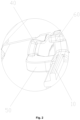
Fig. 2 illustrates a partial enlarged diagram of a position A inFig. 1 ; -
Fig. 3 illustrates a structure schematic diagram of a first position limiting member inFig. 1 ; -
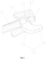
Fig. 4 illustrates a structure schematic diagram of a second position limiting member inFig. 1 ; and -
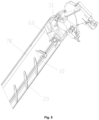
Fig. 5 illustrates another view of the air regulating device inFig. 1 . - Herein, the above drawings include the following reference signs.
- 10. rotation shaft; 11. plug; 20. blade; 31. fixing portion; 31a. housing; 31b. shaft sleeve; 32. driving shaft; 32a. slot; 32b. lug boss; 40. first position limiting member; 41. first connecting section; 42. first extending section; 50. second position limiting member; 51. second connecting section; 52. second extending section; 60. locking button; 61. cantilever; 62. locking hook; 63. handle; and 70. air guiding assembly.
- Technical solutions in the embodiments of the invention are clearly and completely described below in combination with the drawings in the embodiments of the disclosure. It is apparent that the embodiments described are only a part of the embodiments of the invention, but not all of the possible embodiments of the invention. The following description to at least one exemplary embodiment is actually merely illustrative, and is in no way served as any limitation to the invention or use thereof.
- As shown in
Fig. 1 to Fig. 5 , the embodiment of the invention provides an air sweeping assembly, including: arotation shaft 10, wherein therotation shaft 10 is provided withblades 20; a driving device, wherein the driving device includes a fixingportion 31 and a driving portion disposed on the fixingportion 31; the driving portion is drivingly connected with therotation shaft 10, and the driving portion is configured to drive therotation shaft 10 to rotate; and a firstposition limiting member 40 disposed on the fixingportion 31; wherein the firstposition limiting member 40 is configured to define an initial position of therotation shaft 10 in a circumferential direction. - The technical solution of the invention is applied, to enable the first
position limiting member 40 of the air sweeping assembly to be disposed on the fixing portion of the driving device, and the initial position of therotation shaft 10 in the circumferential direction is defined by the firstposition limiting member 40. Because the firstposition limiting member 40 is positioned on astationary fixing portion 31, the position of the firstposition limiting member 40 is stationary, whenever therotation shaft 10 is rotated to a position in which the rotation shaft is contacted with the firstposition limiting member 40, therotation shaft 10 has a defined known position, a position is used as the initial position of therotation shaft 10 and theblades 20, so that the initial position of theblades 20 is defined conveniently, and a rotation angle of theblades 20 is regulated conveniently. In addition, such a structure is used so that a program for controlling theblades 20 to find the initial position can also be set simply. - In this way, no matter where the
blades 20 are positioned while the whole air conditioner is started, it is necessary to start rotation calculation from the initial position, and then rotated to a predetermined angle to be achieved to perform the air sweeping. The firstposition limiting member 40 in some embodiments is a static reference object without motion properties, it is great convenient to find the initial position for theblades 20, thereby the control program of theblades 20 can be simplified, and a fixed-angle air sweeping of theblades 20 is achieved. - As shown in
Fig. 1 andFig. 2 , the air sweeping assembly further includes: a secondposition limiting member 50 disposed on therotation shaft 10, wherein the secondposition limiting member 50 is configured to contact with the firstposition limiting member 40 so as to define the initial position of therotation shaft 10 in the circumferential direction. In such setting, while therotation shaft 10 is rotated to a certain position, the secondposition limiting member 50 is contacted with the firstposition limiting member 40, so as to prevent therotation shaft 10 from being continuously rotated, this position is served as an initial position of therotation shaft 10 and theblades 20. In this way, while the initial position of theblades 20 is required to be defined, just therotation shaft 10 is rotated. When the secondposition limiting member 50 is contacted with the firstposition limiting member 40, the initial position is acquired, so that the initial position of theblades 20 is defined conveniently, and a rotation angle of theblades 20 is regulated conveniently. - As shown in
Fig. 3 , the firstposition limiting member 40 includes: a first connectingsection 41, protrudingly disposed on the fixing portion and disposed on the fixingportion 31; and a first extendingsection 42, connected with the first connectingsection 41, wherein the first extendingsection 42 is extended along an axial direction of therotation shaft 10, and the first extendingsection 42 is configured to abut against the secondposition limiting member 50. In such setting, the firstposition limiting member 40 is contacted with the secondposition limiting member 50 conveniently, thereby the initial position of therotation shaft 10 and theblades 20 is defined conveniently. - As shown in
Fig. 4 , the secondposition limiting member 50 includes: a second connectingsection 51, protrudingly disposed on the rotation shaft and disposed on therotation shaft 10; and a second extendingsection 52, connected with the second connectingsection 51, wherein the second extendingsection 52 is extended along the axial direction of therotation shaft 10, and the second extendingsection 52 is configured to abut against the firstposition limiting member 40. In such setting, the firstposition limiting member 40 is contacted with the secondposition limiting member 50 conveniently, thereby the initial position of therotation shaft 10 and theblades 20 is defined conveniently. In some embodiments, while therotation shaft 10 is rotated to the initial position, the first extendingsection 42 of the firstposition limiting member 40 is contacted with the second extendingsection 52 of the secondposition limiting member 50, thereby therotation shaft 10 is limited in the initial position, after the initial position is defined, the rotation angle of theblades 20 is regulated conveniently. - As shown in
Fig. 3 , the fixingportion 31 includes: ahousing 31a, wherein at least part of the driving portion is disposed in thehousing 31a; and ashaft sleeve 31b, connected with thehousing 31a, wherein the firstposition limiting member 40 is protrudingly disposed on the shaft sleeve and disposed on theshaft sleeve 31b, and a drivingshaft 32 of the driving portion is passed through theshaft sleeve 31b. In this way, the firstposition limiting member 40 is conveniently installed and an avoidance is performed on the drivingshaft 32 of the driving portion. - According to the invention, the driving
shaft 32 of the driving portion is provided with aslot 32a, an inside of theslot 32a is provided with a first limiting surface, an end part of therotation shaft 10 is provided with aplug 11, theplug 11 is provided with a second limiting surface, theplug 11 is in insert-connection with theslot 32a, and the first limiting surface is cooperated with the second limiting surface. In such setting, the connection of therotation shaft 10 and the drivingshaft 32 is achieved in an insert-connection manner, and a transfer of a force torque is achieved by a cooperation of the first limiting surface and the second limiting surface. So, it is convenient to an assembly of therotation shaft 10 and the drivingshaft 32 by a technical solution of some embodiments of the present disclosure. - Accortding to the present invention, an inside of the
slot 32a is provided with a plurality of first limiting surfaces, an outer side of theplug 11 is provided with a plurality of second limiting surfaces, the plurality of second limiting surfaces are in cooperative-connection with the plurality of first limiting surfaces each other. In such setting, the connection reliability of therotation shaft 10 and the drivingshaft 32 is improved, and therotation shaft 10 and the drivingshaft 32 are prevented from being relatively moved, so that the torque is transferred better. For example, in some embodiments, a cross section of theslot 32a and a cross section of theplug 11 are set as mutually matched hexagonal structures. - In order to improve a connection strengthen of the
rotation shaft 10 and the drivingshaft 32, according to the invention, the air sweeping assembly further includes: a lockingbutton 60, disposed at one end, adjacent to the driving portion, of therotation shaft 10, wherein, the drivingshaft 32 of the driving portion is provided with alug boss 32b, thelocking button 60 is in locking-connection with thelug boss 32b so as to prevent therotation shaft 10 from being axially moved relative to the drivingshaft 32. In such setting, therotation shaft 10 is prevented from being axially moved relative to the drivingshaft 32 by a locking-connection of thelocking button 60 and thelug boss 32b, thereby a reliability of the sweeping assembly is guaranteed. In addition, a connection manner of the locking-connection is convenient to the assembly of the sweeping assembly. - As shown in
Fig. 4 , thelocking button 60 includes: acantilever 61, protrudingly disposed on therotation shaft 10 and disposed on therotation shaft 10; and alocking hook 62, connected with thecantilever 61, wherein, the lockinghook 62 is in locking-connection with thelug boss 32b. In this way, enough space is reserved to install thelocking button 60 conveniently. After thelocking hook 62 is in locking-connection with thelug boss 32b, a connecting part of thelug boss 32b is positioned in an area between thecantilever 61 and the lockinghook 62. - According to the present invention, the
locking button 60 further includes: ahandle 63, one end of thehandle 63 is connected with the lockinghook 62, and the other end of thehandle 63 is a free end, thehandle 63 and the lockinghook 62 are respectively positioned at both sides of thecantilever 61. In this way, thehandle 63, thecantilever 61 and the lockinghook 62 form a leverage effect, in operation, thehandle 63 is pressed so that thehandle 63 is moved to a direction adjacent to therotation shaft 10, thereby the lockinghook 62 is moved to a direction away from therotation shaft 10, in this way, the lockinghook 62 has enough avoidance space to connect or disconnect with thelug boss 32b. So, it is convenient to an assembly of therotation shaft 10 and the drivingshaft 32 by the technical solution of some embodiments of the present disclosure. - In order to improve the connection strength of the
rotation shaft 10 and the drivingshaft 32, in some embodiments of the present invention, twosymmetric locking buttons 60 are installed, and the two lockingbuttons 60 are respectively connected with thelug boss 32b. In addition, in some embodiments, after the lockinghook 62 is connected with thelug boss 32b, theshaft sleeve 31b also has a limiting effect on the lockinghook 62. In some embodiments, thelocking button 60 is made of an elastic material. For example, the lockingbuttons 60 and therotation shaft 10 are integrally injection-formed by using a plastic material. - Some embodiments of the present invention further provide an air regulating device, the air regulating device includes an
air guiding assembly 70 and the above mentioned air sweeping assembly, arotation shaft 10 of the air sweeping assembly is disposed on theair guiding assembly 70. The technical solution of the embodiments is applied, to enable the firstposition limiting member 40 of the air sweeping assembly to be disposed on the fixingportion 31 of the driving device, and the initial position of therotation shaft 10 in the circumferential direction is defined by the firstposition limiting member 40. Because the firstposition limiting member 40 is positioned on thestationary fixing portion 31, the position of the firstposition limiting member 40 is stationary, whenever therotation shaft 10 is rotated to a position in which therotation shaft 10 is contacted with the firstposition limiting member 40, therotation shaft 10 has a defined known position, the position is used as the initial position of therotation shaft 10 and theblades 20, so that the initial position of theblades 20 is defined conveniently, and a rotation angle of theblades 20 is regulated conveniently. The air regulating device is set to include the air sweeping assembly and theair guiding assembly 70, a same set of the device can be used to achieve the regulation of air blown out from the air conditioner in left-right direction and upward-downward direction, thereby the comfort level of a user is improved and the air regulating device is enabled to be more compact. - Some embodiments of the present invention provide an air conditioner. The air conditioner includes an air regulating device, the air regulating device is the air regulating device provided by the above embodiments. By using the air conditioner, the initial position of the
blades 20 is defined conveniently, thereby the rotation angle of theblades 20 is regulated conveniently. - The above are only the embodiments of the invention, and are not intended to limit the scope of protection which is limited by the appended claims.
Claims (7)
- An air sweeping assembly, comprising:a rotation shaft (10), the rotation shaft (10) being provided with blades (20);a driving device, wherein the driving device comprises a fixing portion (31) and a driving portion disposed on the fixing portion (31); the driving portion is drivingly connected with the rotation shaft (10), and the driving portion is configured to drive the rotation shaft (10) to rotate; anda first position limiting member (40) disposed on the fixing portion (31), wherein the first position limiting member (40) is configured to define an initial position of the rotation shaft (10) in a circumferential direction;wherein a driving shaft (32) of the driving portion is provided with a slot (32a), an inside of the slot (32a) is provided with a first limiting surface, an end part of the rotation shaft (10) is provided with a plug (11), the plug (11) is provided with a second limiting surface, the plug (11) is in insert-connection with the slot (32a), and the first limiting surface is cooperated with the second limiting surface;characterized by further comprising:a locking button (60), disposed at one end, adjacent to the driving portion, of the rotation shaft (10), wherein, a driving shaft (32) of the driving portion is provided with a lug boss (32b), the locking button (60) is in locking-connection with the lug boss (32b) so as to prevent the rotation shaft (10) from being axially moved relative to the driving shaft (32);wherein the locking button (60) comprises:a cantilever (61), protrudingly disposed on the rotation shaft (10) and disposed on the rotation shaft (10); anda locking hook (62), connected with the cantilever (61), wherein, the locking hook (62) is in locking-connection with the lug boss (32b);a handle (63), one end of the handle (63) is connected with the locking hook (62), and the other end of the handle (63) is a free end, the handle (63) and the locking hook (62) are respectively positioned at both sides of the cantilever (61).
- The air sweeping assembly as claimed in claim 1, further comprising:
a second position limiting member (50) disposed on the rotation shaft (10), the second position limiting member (50) being configured to contact with the first position limiting member (40), so as to define the initial position of the rotation shaft (10) in the circumferential direction. - The air sweeping assembly as claimed in claim 2, wherein the first position limiting member (40) comprises:a first connecting section (41), protrudingly disposed on the fixing portion (31) and disposed on the fixing portion (31); anda first extending section (42), connected with the first connecting section (41), the first extending section (42) being extended along an axial direction of the rotation shaft (10), and the first extending section (42) being configured to abut against the second position limiting member (50).
- The air sweeping assembly as claimed in claim 2, wherein the second position limiting member (50) comprises:a second connecting section (51), protrudingly disposed on the rotation shaft (10) and disposed on the rotation shaft (10); anda second extending section (52), connected with the second connecting section (51), the second extending section (52) being extended along the axial direction of the rotation shaft (10), and the second extending section (52) being configured to abut against the first position limiting member (40).
- The air sweeping assembly as claimed in claim 1, wherein the fixing portion (31) comprises:a housing (31a), at least part of the driving portion being disposed in the housing (31a); anda shaft sleeve (31b), connected with the housing (31a), the first position limiting member (40) being protrudingly disposed on the shaft sleeve (31b) and disposed on the shaft sleeve (31b), and a driving shaft (32) of the driving portion being passed through the shaft sleeve (31b).
- An air regulating device, comprising an air guiding assembly (70) and an air sweeping assembly as claimed in any one of claims 1 to 5, wherein, the rotation shaft (10) of the air sweeping assembly is disposed on the air guiding assembly (70).
- An air conditioner, comprising the air regulating device as claimed in claim 6.
Applications Claiming Priority (2)
| Application Number | Priority Date | Filing Date | Title |
|---|---|---|---|
| CN201810141417.8A CN108518834B (en) | 2018-02-11 | 2018-02-11 | Sweep wind subassembly, air adjusting device and air conditioner |
| PCT/CN2018/120014 WO2019153868A1 (en) | 2018-02-11 | 2018-12-10 | Air sweeping module, air regulating device and air conditioner |
Publications (3)
| Publication Number | Publication Date |
|---|---|
| EP3751214A1 EP3751214A1 (en) | 2020-12-16 |
| EP3751214A4 EP3751214A4 (en) | 2021-03-24 |
| EP3751214B1 true EP3751214B1 (en) | 2024-09-11 |
Family
ID=63433166
Family Applications (1)
| Application Number | Title | Priority Date | Filing Date |
|---|---|---|---|
| EP18905001.6A Active EP3751214B1 (en) | 2018-02-11 | 2018-12-10 | Air sweeping module, air regulating device and air conditioner |
Country Status (4)
| Country | Link |
|---|---|
| US (1) | US11788765B2 (en) |
| EP (1) | EP3751214B1 (en) |
| CN (1) | CN108518834B (en) |
| WO (1) | WO2019153868A1 (en) |
Families Citing this family (3)
| Publication number | Priority date | Publication date | Assignee | Title |
|---|---|---|---|---|
| CN108518834B (en) | 2018-02-11 | 2020-05-29 | 珠海格力电器股份有限公司 | Sweep wind subassembly, air adjusting device and air conditioner |
| CN108954771A (en) * | 2018-09-18 | 2018-12-07 | 珠海格力电器股份有限公司 | Sweep wind blade subassembly and air conditioner |
| CN115046302B (en) * | 2022-07-11 | 2024-11-29 | 珠海格力电器股份有限公司 | Air guide structure, air conditioner and air conditioning control method |
Family Cites Families (12)
| Publication number | Priority date | Publication date | Assignee | Title |
|---|---|---|---|---|
| US4090373A (en) * | 1977-01-24 | 1978-05-23 | Carrier Corporation | Apparatus for controlling an internal door of an air conditioning unit |
| CN201628345U (en) * | 2010-02-05 | 2010-11-10 | 广东格兰仕集团有限公司 | Air guide structure of split wall-mounted air conditioner indoor unit |
| KR101252183B1 (en) * | 2011-05-16 | 2013-04-09 | 주식회사 삼원이.엔.지 | System damper |
| CN103528175B (en) * | 2013-10-09 | 2017-09-15 | Tcl空调器(中山)有限公司 | Air conditioner and its air ducting |
| CN103900233B (en) * | 2014-04-17 | 2016-11-02 | 青岛海信日立空调系统有限公司 | Wind guiding component, air-conditioning and air conditioner air deflector control method |
| CN106481679A (en) * | 2016-09-26 | 2017-03-08 | 珠海格力电器股份有限公司 | Connecting piece and motor drive shaft's mounting structure |
| CN206890770U (en) * | 2017-05-20 | 2018-01-16 | 法狮龙建材科技有限公司 | The wind outlet unit of Integral ceiling |
| CN107606765B (en) * | 2017-08-09 | 2020-12-08 | Tcl空调器(中山)有限公司 | Air Conditioning Panel Assembly |
| CN107525149B (en) * | 2017-09-12 | 2023-07-14 | 珠海格力电器股份有限公司 | Air guide mechanism and air conditioner with same |
| CN107560135B (en) * | 2017-09-12 | 2023-07-14 | 珠海格力电器股份有限公司 | Air deflector assembly and air conditioner with same |
| CN108518834B (en) * | 2018-02-11 | 2020-05-29 | 珠海格力电器股份有限公司 | Sweep wind subassembly, air adjusting device and air conditioner |
| CN208012029U (en) * | 2018-02-11 | 2018-10-26 | 珠海格力电器股份有限公司 | Sweep wind subassembly, air adjusting device and air conditioner |
-
2018
- 2018-02-11 CN CN201810141417.8A patent/CN108518834B/en active Active
- 2018-12-10 EP EP18905001.6A patent/EP3751214B1/en active Active
- 2018-12-10 US US16/969,144 patent/US11788765B2/en active Active
- 2018-12-10 WO PCT/CN2018/120014 patent/WO2019153868A1/en not_active Ceased
Also Published As
| Publication number | Publication date |
|---|---|
| US20210041133A1 (en) | 2021-02-11 |
| CN108518834A (en) | 2018-09-11 |
| EP3751214A4 (en) | 2021-03-24 |
| EP3751214A1 (en) | 2020-12-16 |
| CN108518834B (en) | 2020-05-29 |
| US20210356166A9 (en) | 2021-11-18 |
| WO2019153868A1 (en) | 2019-08-15 |
| US11788765B2 (en) | 2023-10-17 |
Similar Documents
| Publication | Publication Date | Title |
|---|---|---|
| WO2021209002A1 (en) | Air vent assembly | |
| US11788765B2 (en) | Air sweeping assembly, air regulating device and air conditioner | |
| CN109442720B (en) | Louver assembly for air-conditioning indoor unit and air-conditioning indoor unit having the same | |
| CN107606765B (en) | Air Conditioning Panel Assembly | |
| CN108679727B (en) | Air sweeping mechanism and air conditioner with same | |
| CN117087386A (en) | A damper control mechanism, air-conditioning air outlet device and automobile | |
| US20190111766A1 (en) | Air Vent for a Transport Vehicle | |
| CN111121174B (en) | Fan assembly, window air conditioner and control method of window air conditioner | |
| EP4596277A1 (en) | Air outlet device and automobile | |
| CN211977200U (en) | Air guide assembly and air treatment device | |
| JP4703336B2 (en) | Air conditioner | |
| CN219809976U (en) | Air duct machine | |
| CN105465988A (en) | Wind sweeping structure and panel assembly | |
| CN215398079U (en) | Vehicle air conditioning system | |
| CN217503840U (en) | Panel assembly and air conditioning equipment | |
| JP5364480B2 (en) | Driving plate | |
| CN205448223U (en) | Wind sweeping structure and panel assembly | |
| CN222223860U (en) | Manual and automatic air outlet assembly device | |
| US11560044B2 (en) | Ventilation device for an automobile passenger compartment | |
| CN117698383A (en) | Air outlet device and automobile | |
| CN215723651U (en) | Machine and air conditioner in air conditioning | |
| CN219037038U (en) | Wind shielding assembly and air conditioner | |
| EP4375579B1 (en) | Air conditioner | |
| CN111391618B (en) | Switch control mechanism for double channels, air conditioning system and vehicle | |
| CN218972897U (en) | A heater and its hovering structure |
Legal Events
| Date | Code | Title | Description |
|---|---|---|---|
| STAA | Information on the status of an ep patent application or granted ep patent |
Free format text: STATUS: THE INTERNATIONAL PUBLICATION HAS BEEN MADE |
|
| PUAI | Public reference made under article 153(3) epc to a published international application that has entered the european phase |
Free format text: ORIGINAL CODE: 0009012 |
|
| STAA | Information on the status of an ep patent application or granted ep patent |
Free format text: STATUS: REQUEST FOR EXAMINATION WAS MADE |
|
| 17P | Request for examination filed |
Effective date: 20200812 |
|
| AK | Designated contracting states |
Kind code of ref document: A1 Designated state(s): AL AT BE BG CH CY CZ DE DK EE ES FI FR GB GR HR HU IE IS IT LI LT LU LV MC MK MT NL NO PL PT RO RS SE SI SK SM TR |
|
| AX | Request for extension of the european patent |
Extension state: BA ME |
|
| A4 | Supplementary search report drawn up and despatched |
Effective date: 20210218 |
|
| RIC1 | Information provided on ipc code assigned before grant |
Ipc: F24F 1/0057 20190101ALI20210212BHEP Ipc: F24F 13/15 20060101ALI20210212BHEP Ipc: F24F 1/0011 20190101ALI20210212BHEP Ipc: F24F 13/14 20060101ALI20210212BHEP Ipc: F24F 13/10 20060101AFI20210212BHEP |
|
| DAV | Request for validation of the european patent (deleted) | ||
| DAX | Request for extension of the european patent (deleted) | ||
| STAA | Information on the status of an ep patent application or granted ep patent |
Free format text: STATUS: EXAMINATION IS IN PROGRESS |
|
| 17Q | First examination report despatched |
Effective date: 20230124 |
|
| P01 | Opt-out of the competence of the unified patent court (upc) registered |
Effective date: 20230530 |
|
| GRAP | Despatch of communication of intention to grant a patent |
Free format text: ORIGINAL CODE: EPIDOSNIGR1 |
|
| STAA | Information on the status of an ep patent application or granted ep patent |
Free format text: STATUS: GRANT OF PATENT IS INTENDED |
|
| INTG | Intention to grant announced |
Effective date: 20240624 |
|
| GRAS | Grant fee paid |
Free format text: ORIGINAL CODE: EPIDOSNIGR3 |
|
| GRAA | (expected) grant |
Free format text: ORIGINAL CODE: 0009210 |
|
| STAA | Information on the status of an ep patent application or granted ep patent |
Free format text: STATUS: THE PATENT HAS BEEN GRANTED |
|
| AK | Designated contracting states |
Kind code of ref document: B1 Designated state(s): AL AT BE BG CH CY CZ DE DK EE ES FI FR GB GR HR HU IE IS IT LI LT LU LV MC MK MT NL NO PL PT RO RS SE SI SK SM TR |
|
| REG | Reference to a national code |
Ref country code: GB Ref legal event code: FG4D |
|
| REG | Reference to a national code |
Ref country code: CH Ref legal event code: EP |
|
| REG | Reference to a national code |
Ref country code: DE Ref legal event code: R096 Ref document number: 602018074401 Country of ref document: DE |
|
| REG | Reference to a national code |
Ref country code: IE Ref legal event code: FG4D |
|
| REG | Reference to a national code |
Ref country code: LT Ref legal event code: MG9D |
|
| PG25 | Lapsed in a contracting state [announced via postgrant information from national office to epo] |
Ref country code: NO Free format text: LAPSE BECAUSE OF FAILURE TO SUBMIT A TRANSLATION OF THE DESCRIPTION OR TO PAY THE FEE WITHIN THE PRESCRIBED TIME-LIMIT Effective date: 20241211 |
|
| REG | Reference to a national code |
Ref country code: NL Ref legal event code: MP Effective date: 20240911 |
|
| PG25 | Lapsed in a contracting state [announced via postgrant information from national office to epo] |
Ref country code: FI Free format text: LAPSE BECAUSE OF FAILURE TO SUBMIT A TRANSLATION OF THE DESCRIPTION OR TO PAY THE FEE WITHIN THE PRESCRIBED TIME-LIMIT Effective date: 20240911 Ref country code: GR Free format text: LAPSE BECAUSE OF FAILURE TO SUBMIT A TRANSLATION OF THE DESCRIPTION OR TO PAY THE FEE WITHIN THE PRESCRIBED TIME-LIMIT Effective date: 20241212 |
|
| PG25 | Lapsed in a contracting state [announced via postgrant information from national office to epo] |
Ref country code: BG Free format text: LAPSE BECAUSE OF FAILURE TO SUBMIT A TRANSLATION OF THE DESCRIPTION OR TO PAY THE FEE WITHIN THE PRESCRIBED TIME-LIMIT Effective date: 20240911 |
|
| PG25 | Lapsed in a contracting state [announced via postgrant information from national office to epo] |
Ref country code: LV Free format text: LAPSE BECAUSE OF FAILURE TO SUBMIT A TRANSLATION OF THE DESCRIPTION OR TO PAY THE FEE WITHIN THE PRESCRIBED TIME-LIMIT Effective date: 20240911 |
|
| PG25 | Lapsed in a contracting state [announced via postgrant information from national office to epo] |
Ref country code: HR Free format text: LAPSE BECAUSE OF FAILURE TO SUBMIT A TRANSLATION OF THE DESCRIPTION OR TO PAY THE FEE WITHIN THE PRESCRIBED TIME-LIMIT Effective date: 20240911 |
|
| PG25 | Lapsed in a contracting state [announced via postgrant information from national office to epo] |
Ref country code: ES Free format text: LAPSE BECAUSE OF FAILURE TO SUBMIT A TRANSLATION OF THE DESCRIPTION OR TO PAY THE FEE WITHIN THE PRESCRIBED TIME-LIMIT Effective date: 20240911 Ref country code: RS Free format text: LAPSE BECAUSE OF FAILURE TO SUBMIT A TRANSLATION OF THE DESCRIPTION OR TO PAY THE FEE WITHIN THE PRESCRIBED TIME-LIMIT Effective date: 20241211 |
|
| PG25 | Lapsed in a contracting state [announced via postgrant information from national office to epo] |
Ref country code: RS Free format text: LAPSE BECAUSE OF FAILURE TO SUBMIT A TRANSLATION OF THE DESCRIPTION OR TO PAY THE FEE WITHIN THE PRESCRIBED TIME-LIMIT Effective date: 20241211 Ref country code: NO Free format text: LAPSE BECAUSE OF FAILURE TO SUBMIT A TRANSLATION OF THE DESCRIPTION OR TO PAY THE FEE WITHIN THE PRESCRIBED TIME-LIMIT Effective date: 20241211 Ref country code: LV Free format text: LAPSE BECAUSE OF FAILURE TO SUBMIT A TRANSLATION OF THE DESCRIPTION OR TO PAY THE FEE WITHIN THE PRESCRIBED TIME-LIMIT Effective date: 20240911 Ref country code: HR Free format text: LAPSE BECAUSE OF FAILURE TO SUBMIT A TRANSLATION OF THE DESCRIPTION OR TO PAY THE FEE WITHIN THE PRESCRIBED TIME-LIMIT Effective date: 20240911 Ref country code: GR Free format text: LAPSE BECAUSE OF FAILURE TO SUBMIT A TRANSLATION OF THE DESCRIPTION OR TO PAY THE FEE WITHIN THE PRESCRIBED TIME-LIMIT Effective date: 20241212 Ref country code: FI Free format text: LAPSE BECAUSE OF FAILURE TO SUBMIT A TRANSLATION OF THE DESCRIPTION OR TO PAY THE FEE WITHIN THE PRESCRIBED TIME-LIMIT Effective date: 20240911 Ref country code: ES Free format text: LAPSE BECAUSE OF FAILURE TO SUBMIT A TRANSLATION OF THE DESCRIPTION OR TO PAY THE FEE WITHIN THE PRESCRIBED TIME-LIMIT Effective date: 20240911 Ref country code: BG Free format text: LAPSE BECAUSE OF FAILURE TO SUBMIT A TRANSLATION OF THE DESCRIPTION OR TO PAY THE FEE WITHIN THE PRESCRIBED TIME-LIMIT Effective date: 20240911 |
|
| REG | Reference to a national code |
Ref country code: AT Ref legal event code: MK05 Ref document number: 1723021 Country of ref document: AT Kind code of ref document: T Effective date: 20240911 |
|
| PG25 | Lapsed in a contracting state [announced via postgrant information from national office to epo] |
Ref country code: NL Free format text: LAPSE BECAUSE OF FAILURE TO SUBMIT A TRANSLATION OF THE DESCRIPTION OR TO PAY THE FEE WITHIN THE PRESCRIBED TIME-LIMIT Effective date: 20240911 |
|
| PG25 | Lapsed in a contracting state [announced via postgrant information from national office to epo] |
Ref country code: IS Free format text: LAPSE BECAUSE OF FAILURE TO SUBMIT A TRANSLATION OF THE DESCRIPTION OR TO PAY THE FEE WITHIN THE PRESCRIBED TIME-LIMIT Effective date: 20250111 Ref country code: PT Free format text: LAPSE BECAUSE OF FAILURE TO SUBMIT A TRANSLATION OF THE DESCRIPTION OR TO PAY THE FEE WITHIN THE PRESCRIBED TIME-LIMIT Effective date: 20250113 |
|
| PG25 | Lapsed in a contracting state [announced via postgrant information from national office to epo] |
Ref country code: RO Free format text: LAPSE BECAUSE OF FAILURE TO SUBMIT A TRANSLATION OF THE DESCRIPTION OR TO PAY THE FEE WITHIN THE PRESCRIBED TIME-LIMIT Effective date: 20240911 Ref country code: SM Free format text: LAPSE BECAUSE OF FAILURE TO SUBMIT A TRANSLATION OF THE DESCRIPTION OR TO PAY THE FEE WITHIN THE PRESCRIBED TIME-LIMIT Effective date: 20240911 |
|
| PG25 | Lapsed in a contracting state [announced via postgrant information from national office to epo] |
Ref country code: EE Free format text: LAPSE BECAUSE OF FAILURE TO SUBMIT A TRANSLATION OF THE DESCRIPTION OR TO PAY THE FEE WITHIN THE PRESCRIBED TIME-LIMIT Effective date: 20240911 Ref country code: AT Free format text: LAPSE BECAUSE OF FAILURE TO SUBMIT A TRANSLATION OF THE DESCRIPTION OR TO PAY THE FEE WITHIN THE PRESCRIBED TIME-LIMIT Effective date: 20240911 |
|
| PG25 | Lapsed in a contracting state [announced via postgrant information from national office to epo] |
Ref country code: CZ Free format text: LAPSE BECAUSE OF FAILURE TO SUBMIT A TRANSLATION OF THE DESCRIPTION OR TO PAY THE FEE WITHIN THE PRESCRIBED TIME-LIMIT Effective date: 20240911 Ref country code: PL Free format text: LAPSE BECAUSE OF FAILURE TO SUBMIT A TRANSLATION OF THE DESCRIPTION OR TO PAY THE FEE WITHIN THE PRESCRIBED TIME-LIMIT Effective date: 20240911 |
|
| PG25 | Lapsed in a contracting state [announced via postgrant information from national office to epo] |
Ref country code: SK Free format text: LAPSE BECAUSE OF FAILURE TO SUBMIT A TRANSLATION OF THE DESCRIPTION OR TO PAY THE FEE WITHIN THE PRESCRIBED TIME-LIMIT Effective date: 20240911 |
|
| REG | Reference to a national code |
Ref country code: DE Ref legal event code: R097 Ref document number: 602018074401 Country of ref document: DE |
|
| PG25 | Lapsed in a contracting state [announced via postgrant information from national office to epo] |
Ref country code: MC Free format text: LAPSE BECAUSE OF FAILURE TO SUBMIT A TRANSLATION OF THE DESCRIPTION OR TO PAY THE FEE WITHIN THE PRESCRIBED TIME-LIMIT Effective date: 20240911 |
|
| PG25 | Lapsed in a contracting state [announced via postgrant information from national office to epo] |
Ref country code: DK Free format text: LAPSE BECAUSE OF FAILURE TO SUBMIT A TRANSLATION OF THE DESCRIPTION OR TO PAY THE FEE WITHIN THE PRESCRIBED TIME-LIMIT Effective date: 20240911 |
|
| PLBE | No opposition filed within time limit |
Free format text: ORIGINAL CODE: 0009261 |
|
| STAA | Information on the status of an ep patent application or granted ep patent |
Free format text: STATUS: NO OPPOSITION FILED WITHIN TIME LIMIT |
|
| REG | Reference to a national code |
Ref country code: CH Ref legal event code: PL |
|
| PG25 | Lapsed in a contracting state [announced via postgrant information from national office to epo] |
Ref country code: LU Free format text: LAPSE BECAUSE OF NON-PAYMENT OF DUE FEES Effective date: 20241210 |
|
| 26N | No opposition filed |
Effective date: 20250612 |
|
| GBPC | Gb: european patent ceased through non-payment of renewal fee |
Effective date: 20241211 |
|
| PG25 | Lapsed in a contracting state [announced via postgrant information from national office to epo] |
Ref country code: SE Free format text: LAPSE BECAUSE OF FAILURE TO SUBMIT A TRANSLATION OF THE DESCRIPTION OR TO PAY THE FEE WITHIN THE PRESCRIBED TIME-LIMIT Effective date: 20240911 |
|
| REG | Reference to a national code |
Ref country code: BE Ref legal event code: MM Effective date: 20241231 |
|
| PG25 | Lapsed in a contracting state [announced via postgrant information from national office to epo] |
Ref country code: GB Free format text: LAPSE BECAUSE OF NON-PAYMENT OF DUE FEES Effective date: 20241211 Ref country code: BE Free format text: LAPSE BECAUSE OF NON-PAYMENT OF DUE FEES Effective date: 20241231 |
|
| PG25 | Lapsed in a contracting state [announced via postgrant information from national office to epo] |
Ref country code: FR Free format text: LAPSE BECAUSE OF NON-PAYMENT OF DUE FEES Effective date: 20241231 |
|
| PG25 | Lapsed in a contracting state [announced via postgrant information from national office to epo] |
Ref country code: CH Free format text: LAPSE BECAUSE OF NON-PAYMENT OF DUE FEES Effective date: 20241231 |
|
| PG25 | Lapsed in a contracting state [announced via postgrant information from national office to epo] |
Ref country code: IE Free format text: LAPSE BECAUSE OF NON-PAYMENT OF DUE FEES Effective date: 20241210 |
|
| PGFP | Annual fee paid to national office [announced via postgrant information from national office to epo] |
Ref country code: DE Payment date: 20251222 Year of fee payment: 8 |
|
| PGFP | Annual fee paid to national office [announced via postgrant information from national office to epo] |
Ref country code: IT Payment date: 20251231 Year of fee payment: 8 |