EP3751201B1 - Cross fire tube installation/removal method and apparatus - Google Patents
Cross fire tube installation/removal method and apparatus Download PDFInfo
- Publication number
- EP3751201B1 EP3751201B1 EP20178626.6A EP20178626A EP3751201B1 EP 3751201 B1 EP3751201 B1 EP 3751201B1 EP 20178626 A EP20178626 A EP 20178626A EP 3751201 B1 EP3751201 B1 EP 3751201B1
- Authority
- EP
- European Patent Office
- Prior art keywords
- fire tube
- cross fire
- removal apparatus
- cross
- spring
- Prior art date
- Legal status (The legal status is an assumption and is not a legal conclusion. Google has not performed a legal analysis and makes no representation as to the accuracy of the status listed.)
- Active
Links
Images



Classifications
-
- F—MECHANICAL ENGINEERING; LIGHTING; HEATING; WEAPONS; BLASTING
- F23—COMBUSTION APPARATUS; COMBUSTION PROCESSES
- F23R—GENERATING COMBUSTION PRODUCTS OF HIGH PRESSURE OR HIGH VELOCITY, e.g. GAS-TURBINE COMBUSTION CHAMBERS
- F23R3/00—Continuous combustion chambers using liquid or gaseous fuel
- F23R3/42—Continuous combustion chambers using liquid or gaseous fuel characterised by the arrangement or form of the flame tubes or combustion chambers
- F23R3/46—Combustion chambers comprising an annular arrangement of several essentially tubular flame tubes within a common annular casing or within individual casings
- F23R3/48—Flame tube interconnectors, e.g. cross-over tubes
-
- B—PERFORMING OPERATIONS; TRANSPORTING
- B25—HAND TOOLS; PORTABLE POWER-DRIVEN TOOLS; MANIPULATORS
- B25B—TOOLS OR BENCH DEVICES NOT OTHERWISE PROVIDED FOR, FOR FASTENING, CONNECTING, DISENGAGING, OR HOLDING
- B25B27/00—Hand tools, specially adapted for fitting together or separating parts or objects whether or not involving some deformation, not otherwise provided for
-
- B—PERFORMING OPERATIONS; TRANSPORTING
- B25—HAND TOOLS; PORTABLE POWER-DRIVEN TOOLS; MANIPULATORS
- B25B—TOOLS OR BENCH DEVICES NOT OTHERWISE PROVIDED FOR, FOR FASTENING, CONNECTING, DISENGAGING, OR HOLDING
- B25B27/00—Hand tools, specially adapted for fitting together or separating parts or objects whether or not involving some deformation, not otherwise provided for
- B25B27/02—Hand tools, specially adapted for fitting together or separating parts or objects whether or not involving some deformation, not otherwise provided for for connecting objects by press fit or detaching same
- B25B27/023—Hand tools, specially adapted for fitting together or separating parts or objects whether or not involving some deformation, not otherwise provided for for connecting objects by press fit or detaching same using screws
-
- B—PERFORMING OPERATIONS; TRANSPORTING
- B25—HAND TOOLS; PORTABLE POWER-DRIVEN TOOLS; MANIPULATORS
- B25B—TOOLS OR BENCH DEVICES NOT OTHERWISE PROVIDED FOR, FOR FASTENING, CONNECTING, DISENGAGING, OR HOLDING
- B25B27/00—Hand tools, specially adapted for fitting together or separating parts or objects whether or not involving some deformation, not otherwise provided for
- B25B27/02—Hand tools, specially adapted for fitting together or separating parts or objects whether or not involving some deformation, not otherwise provided for for connecting objects by press fit or detaching same
- B25B27/06—Hand tools, specially adapted for fitting together or separating parts or objects whether or not involving some deformation, not otherwise provided for for connecting objects by press fit or detaching same inserting or withdrawing sleeves or bearing races
- B25B27/062—Hand tools, specially adapted for fitting together or separating parts or objects whether or not involving some deformation, not otherwise provided for for connecting objects by press fit or detaching same inserting or withdrawing sleeves or bearing races using screws
-
- F—MECHANICAL ENGINEERING; LIGHTING; HEATING; WEAPONS; BLASTING
- F02—COMBUSTION ENGINES; HOT-GAS OR COMBUSTION-PRODUCT ENGINE PLANTS
- F02C—GAS-TURBINE PLANTS; AIR INTAKES FOR JET-PROPULSION PLANTS; CONTROLLING FUEL SUPPLY IN AIR-BREATHING JET-PROPULSION PLANTS
- F02C7/00—Features, components parts, details or accessories, not provided for in, or of interest apart form groups F02C1/00 - F02C6/00; Air intakes for jet-propulsion plants
- F02C7/22—Fuel supply systems
-
- F—MECHANICAL ENGINEERING; LIGHTING; HEATING; WEAPONS; BLASTING
- F23—COMBUSTION APPARATUS; COMBUSTION PROCESSES
- F23R—GENERATING COMBUSTION PRODUCTS OF HIGH PRESSURE OR HIGH VELOCITY, e.g. GAS-TURBINE COMBUSTION CHAMBERS
- F23R3/00—Continuous combustion chambers using liquid or gaseous fuel
- F23R3/42—Continuous combustion chambers using liquid or gaseous fuel characterised by the arrangement or form of the flame tubes or combustion chambers
- F23R3/60—Support structures; Attaching or mounting means
-
- F—MECHANICAL ENGINEERING; LIGHTING; HEATING; WEAPONS; BLASTING
- F05—INDEXING SCHEMES RELATING TO ENGINES OR PUMPS IN VARIOUS SUBCLASSES OF CLASSES F01-F04
- F05D—INDEXING SCHEME FOR ASPECTS RELATING TO NON-POSITIVE-DISPLACEMENT MACHINES OR ENGINES, GAS-TURBINES OR JET-PROPULSION PLANTS
- F05D2230/00—Manufacture
- F05D2230/60—Assembly methods
-
- F—MECHANICAL ENGINEERING; LIGHTING; HEATING; WEAPONS; BLASTING
- F05—INDEXING SCHEMES RELATING TO ENGINES OR PUMPS IN VARIOUS SUBCLASSES OF CLASSES F01-F04
- F05D—INDEXING SCHEME FOR ASPECTS RELATING TO NON-POSITIVE-DISPLACEMENT MACHINES OR ENGINES, GAS-TURBINES OR JET-PROPULSION PLANTS
- F05D2240/00—Components
- F05D2240/35—Combustors or associated equipment
-
- F—MECHANICAL ENGINEERING; LIGHTING; HEATING; WEAPONS; BLASTING
- F23—COMBUSTION APPARATUS; COMBUSTION PROCESSES
- F23R—GENERATING COMBUSTION PRODUCTS OF HIGH PRESSURE OR HIGH VELOCITY, e.g. GAS-TURBINE COMBUSTION CHAMBERS
- F23R2900/00—Special features of, or arrangements for continuous combustion chambers; Combustion processes therefor
- F23R2900/00017—Assembling combustion chamber liners or subparts
-
- F—MECHANICAL ENGINEERING; LIGHTING; HEATING; WEAPONS; BLASTING
- F23—COMBUSTION APPARATUS; COMBUSTION PROCESSES
- F23R—GENERATING COMBUSTION PRODUCTS OF HIGH PRESSURE OR HIGH VELOCITY, e.g. GAS-TURBINE COMBUSTION CHAMBERS
- F23R2900/00—Special features of, or arrangements for continuous combustion chambers; Combustion processes therefor
- F23R2900/00019—Repairing or maintaining combustion chamber liners or subparts
Definitions
- the presently suggested subject matter relates to methods and apparatus for the installation and removal of gas turbine combustor cross fire tubes in a fast, safe, and efficient manner. More in particular, the invention as herein claimed relates to the subject matter set forth in the claims.
- Adjacent combustors of a gas turbine engine are typically connected by a cross fire tube.
- a cross fire tube may extend through the liners, the flow sleeves, and the casings of adjacent combustors to allow the combustion in one combustor to propagate to the adjacent combustor and to ensure substantially simultaneous ignition and equalized pressure in all combustor chambers of the gas turbine engine.
- Cross fire tubes are known for instance from US 2014/0137536 A1 .
- the cross fire tubes need to be removed prior to combustor removal and the like.
- the assembly and/or the location of the cross fire tubes may have one or more disadvantages. For example, current installation and removal methods may be complicated and may result in damage to the cross fire tubes and related components.
- WO 2015/047554 discloses an extractor tool for pulling a sleeve out of a housing, wherein the sleeve exhibits a notch.
- the extractor tool comprises a collet having grasping members at a distal end thereof, wherein the grasping members, in turn, comprise outwardly extending flanges or tabs which fit into the notch.
- the collet with the grasping members is sized so as to provide sufficient clearance between the grasping members and the radially inner surface of the sleeve.
- the grasping members Upon actuation by a treaded shaft the grasping members expand radially to hold against the interior wall of the sleeve, wherein preferably the flanges or tabs are extended into the notch of the sleeve.
- Fig. 1 shows a schematic diagram of gas turbine engine 10 as may be used herein.
- the gas turbine engine 10 may include a compressor 15.
- the compressor 15 compresses an incoming flow of air 20.
- the compressor 15 delivers the compressed flow of air 20 to a number of combustor cans 25.
- the combustor cans 25 mix the compressed flow of air 20 with a pressurized flow of fuel 30 and ignite the mixture to create a flow of hot combustion gases 35.
- the gas turbine engine 10 may include any number of combustor cans 25 positioned in a circumferential array and the like.
- the flow of the hot combustion gases 35 is in turn delivered to a turbine 40.
- the flow of the hot combustion gases 35 drives the turbine 40 so as to produce mechanical work.
- the mechanical work produced in the turbine 40 drives the compressor 15 via a shaft 45 and an external load 50 such as an electrical generator and the like.
- the gas turbine engine 10 may use natural gas, various types of syngas, liquid fuels, and/or other types of fuels and blends thereof.
- the gas turbine engine 10 may be any one of a number of different gas turbine engines offered by General Electric Company of Schenectady, New York, including, but not limited to, those such as a 7 or a 9 series heavy duty gas turbine engine and the like.
- the gas turbine engine 10 may have different configurations and may use other types of components. Other types of gas turbine engines also may be used herein. Multiple gas turbine engines, other types of turbines, and other types of power generation equipment also may be used herein together.
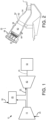
- Fig. 2 shows a schematic diagram of an example of a combustor can 25 as may be used with the gas turbine engine 10 described above and elsewhere.
- the combustor can 25 may extend from an end cap 52 at a head end to a transition piece 54 at an aft end about the turbine 40.
- a number of fuel nozzles 56 may be positioned about the end cap 52.
- a liner 58 may extend from the fuel nozzles 56 towards the transition piece 54 and may define a combustion zone 60 therein.
- the liner 58 may be surrounded by a flow sleeve 62.
- the liner 58 and the flow sleeve 62 may define a flow path 64 therebetween for the flow of air 20 from the compressor 15 or otherwise.
- the combustor can 25 also may include a cross fire tube assembly 66. As described above, the cross fire tube assembly may extend between adjacent combustor cans 25.
- the combustor can 25 described herein is for the purpose of example only. Combustor cans 25 with other components and other configurations may be used herein.
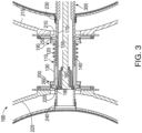
- FIG. 3 shows a cross fire tube installation/removal apparatus 100 with an example of its cross fire tube assembly 110 as may be described herein. As described above, each cross fire tube assembly 110 extends between two adjacent combustor cans 25. Any number of cross fire tube assemblies 110 may be used herein.
- the cross fire tube assembly 110 may have a pair of telescoping sleeves, a first sleeve 120 and a second sleeve 130.
- the first sleeve 120 and the second sleeve 130 may be sized for sliding engagement with one another.
- One or more springs 140 or other type of biasing elements may be in communication with the first sleeve 120 and the second sleeve 130.
- the spring 140 may be a compression spring and the like that circumferentially surrounds at least a portion of the first sleeve 120 and the second sleeve 130.
- the first sleeve 120 may have a first flange 150 at one end thereof and the second sleeve 130 may have a second flange 160 at the opposite end thereof.
- the first flange 150 may have a first groove 170 on an interior surface and the second flange 150 may have a similar second groove 180 thereon.
- the cross fire tube assembly 110 further may include a pair of cross fire tube collars, a first cross fire tube collar 190 and a second cross fire tube collar 200.
- the first cross fire tube collar 190 extends through a first annular passage 210 through the liner 58 and the flow sleeve 62 of a first combustor can 215 and the second cross fire tube collar 200 extends through a second annular passage 220 the liner 58 and the flow sleeve 62 of an adjacent second combustor can 225.
- the first cross fire tube collar 190 may be sized for a friction fit and the like within a first liner collar 230 and the second cross fire tube collar 200 may be sized for a friction fit within a second liner collar 240.
- the first cross fire tube collar 190 may have a first collar flange 250 and the second cross fire tube collar 200 may have a second collar flange 260.
- the collar flanges 250, 260 may be sized to accommodate the sleeve flanges 150, 160.
- the size, shape, and configuration of the overall cross fire tube assembly 110 may vary. Other components and other configurations may be used herein.
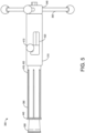
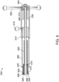
- Figs. 3-7 show an example of a cross fire tube tool 300 of the cross fire tube installation/removal apparatus 100.
- the cross fire tube tool 300 includes a reaction arm 310.
- the reaction arm 310 may be substantially tubular in shape and may be made out of steel or other types of substantially rigid materials.
- the reaction arm 310 may have a driving screw 320 extending therethrough.
- the driving screw 320 may be made out of steel or other types of substantially rigid materials.
- the driving screw 320 may have a number of driving screw threads 330 thereon.
- the driving screw 320 may have any suitable size, shape, or configuration.
- the cross fire tube tool 300 also includes a holder 340 with a number of holder arms 350 positioned at one end of the reaction arm 310.
- the holder 340 may be made out of stainless steel or other types of substantially rigid materials.
- the holder 340 may have an internal driving screw aperture 360 therein.
- the driving screw aperture 360 may have a number of holder threads 370.
- the driving screw aperture 360 may be sized to accommodate the driving screw 320 therein in threaded engagement for movement therewith.
- a holder set screw 380 also may be used.
- the holder arms 350 may be sized and positioned to maneuver the driving screw 320 of the cross fire tube tool 300 as desired.
- the cross fire tube tool 300 comprises a tubular spring 390 positioned partially within and at the other end of the reaction arm 310.
- the tubular spring 390 is substantially tubular in shape and may be made out of steel or other types of substantially rigid materials.
- the tubular spring 390 may have a number of spring slots 400 formed therein so as to give the tubular spring 390 an appropriate amount of compressibility. The size, shape, and configuration of the spring slots 400 may vary.
- the tubular spring 390 is maneuverable within the reaction arm 310 via a locking knob 410 positioned within a locking knob aperture 420 in the reaction arm 310.
- the locking knob 410 may be made out of stainless steel or other types of substantially rigid materials.
- the locking knob aperture 420 may have a number of locking slots 430 formed therein so as to lock the locking knob 410 and the tubular spring 390 in place for insertion or removal of the cross fire tube assembly 110.
- the tubular spring 390 has a spring flange 440 on the opposite end thereof. The spring flange 440 is sized to engage with the grooves 170, 180 of the cross fire tube assembly 110 as described above.
- the cross fire tube tool 300 may have a bearing journal 450 attached one the end of the driving screw 310.
- the bearing journal 450 may have a number of bearing journal threads 460 thereon for threaded engagement with the driving screw 310.
- a bearing journal set screw 470 also may be used.
- the bearing journal 450 may be made out of steel or other types of substantially rigid materials.
- a sleeve bearing 480 may surround the bearing journal 450.
- the sleeve bearing 480 may be made out of brass or other types of substantially rigid materials.
- the bearing journal 450 and the sleeve bearing 480 may be held in place on the driving screw 320 via a hex nut 490 or a similar types of closures.
- a cone end 500 and the like may enclose the bearing journal 450 and the sleeve bearing 480.
- the cone end 500 may be made of steel and similar types of substantially rigid materials. Other components and other configurations may be used herein.
- Figs. 8-11 show the cross fire tube apparatus 100 in operation.
- the cross fire tube tool 300 may be inserted through the first annular passage 210 within the liner 58 and the flow sleeve 62 of the first combustion can 215.
- the cross flow tube assembly 110 then may be placed on the cross fire tube tool 300 between the two adjacent combustor cans 215, 225.
- the cross fire tube tool 300 may be compressed such that the spring flange 440 of the tubular spring 390 engages the second groove 180 in the second flange 160 of the second sleeve 130 of the cross fire tube assembly 110.
- the cone end 500 may be configured to expand the diameter of the tubular spring 390 to lock the spring flange 440 in place.
- Fig. 8 the cross fire tube tool 300 may be inserted through the first annular passage 210 within the liner 58 and the flow sleeve 62 of the first combustion can 215.
- the cross flow tube assembly 110 then may be placed on the cross fire tube tool 300 between the two adjacent comb
- the cross fire tube tool 300 may be further compressed via the driving screw 320 and the holder 340 so as to compress the cross fire tube assembly 110.
- the second collar 200 of the cross fire tube assembly 110 may be positioned within the second passage 220 of the second combustor can 225.
- the compression on the cross fire tool 300 then may be released so as to drive the second sleeve 130 of the cross fire tube assembly 110 into the second collar 200.
- the cross fire tube tool 300 then may be removed.
- the cross fire tube assembly 110 may be removed in largely the opposite fashion.
- Other components and other configurations may be used herein.
- the cross fire tube tool 300 thus may lock into place within the grooves 170, 180 of the cross fire tube assembly 110 for accurate placement given the use of the spring flange 440 and the cone end 500.
- the tubular spring 390 may be mechanically compressed via the driving screw 320.
Landscapes
- Engineering & Computer Science (AREA)
- Mechanical Engineering (AREA)
- Chemical & Material Sciences (AREA)
- Combustion & Propulsion (AREA)
- General Engineering & Computer Science (AREA)
- Feeding And Controlling Fuel (AREA)
- Gas Burners (AREA)
- Quick-Acting Or Multi-Walled Pipe Joints (AREA)
Description
- The presently suggested subject matter relates to methods and apparatus for the installation and removal of gas turbine combustor cross fire tubes in a fast, safe, and efficient manner. More in particular, the invention as herein claimed relates to the subject matter set forth in the claims.
- Adjacent combustors of a gas turbine engine are typically connected by a cross fire tube. Specifically, a cross fire tube may extend through the liners, the flow sleeves, and the casings of adjacent combustors to allow the combustion in one combustor to propagate to the adjacent combustor and to ensure substantially simultaneous ignition and equalized pressure in all combustor chambers of the gas turbine engine. Cross fire tubes are known for instance from
US 2014/0137536 A1 . Generally described, the cross fire tubes need to be removed prior to combustor removal and the like. The assembly and/or the location of the cross fire tubes, however, may have one or more disadvantages. For example, current installation and removal methods may be complicated and may result in damage to the cross fire tubes and related components.WO 2015/047554 discloses an extractor tool for pulling a sleeve out of a housing, wherein the sleeve exhibits a notch. The extractor tool comprises a collet having grasping members at a distal end thereof, wherein the grasping members, in turn, comprise outwardly extending flanges or tabs which fit into the notch. The collet with the grasping members is sized so as to provide sufficient clearance between the grasping members and the radially inner surface of the sleeve. Upon actuation by a treaded shaft the grasping members expand radially to hold against the interior wall of the sleeve, wherein preferably the flanges or tabs are extended into the notch of the sleeve. - The herein claimed invention relates to the subject matter set forth in the claims.
- These and other features and improvements of the present application and the resultant patent will become apparent to one of ordinary skill in the art upon review of the following detailed description when taken in conjunction with the several drawings and the appended claims.
-
-
Fig. 1 is a schematic diagram of a gas turbine engine showing a compressor, a combustor, a turbine, and a load. -
Fig. 2 is a schematic diagram of an example combustor. -
Fig. 3 is a side sectional view of an exemplary cross fire tube installation/removal apparatus as may be described herein with its cross fire tube assembly positioned between adjacent combustor cans. -
Fig. 4 is a perspective of the cross fire tube installation/removal apparatus ofFig. 3 . -
Fig. 5 is a side view of the cross fire tube installation/removal apparatus ofFig. 3 . -
Fig. 6 is a cross-sectional view of the cross fire tube installation/removal apparatus ofFig. 3 taken along line 6-6 ofFig 5 . -
Fig. 7 is a cross-sectional view of the cross fire tube installation/removal apparatus ofFig. 3 taken along line 7-7 ofFig. 5 . -
Fig. 8 is a side view of the cross fire tube installation/removal apparatus in use with its cross fire tube assembly positioned between adjacent combustor cans. -
Fig. 9 is a side view of the cross fire tube installation/removal apparatus in further use with its cross fire tube assembly positioned between adjacent combustor cans. -
Fig. 10 is a side view of the cross fire tube installation/removal apparatus in further use with its cross fire tube assembly positioned between adjacent combustor cans. -
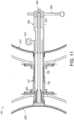
Fig. 11 is a side view of the cross fire tube installation/removal apparatus in further use with its cross fire tube assembly positioned between adjacent combustor cans. - Referring now to the drawings, in which like numerals refer to like elements throughout the several views,
Fig. 1 shows a schematic diagram ofgas turbine engine 10 as may be used herein. Thegas turbine engine 10 may include acompressor 15. Thecompressor 15 compresses an incoming flow ofair 20. Thecompressor 15 delivers the compressed flow ofair 20 to a number ofcombustor cans 25. The combustor cans 25 mix the compressed flow ofair 20 with a pressurized flow offuel 30 and ignite the mixture to create a flow ofhot combustion gases 35. Although only a single combustor can 25 is shown, thegas turbine engine 10 may include any number ofcombustor cans 25 positioned in a circumferential array and the like. The flow of thehot combustion gases 35 is in turn delivered to aturbine 40. The flow of thehot combustion gases 35 drives theturbine 40 so as to produce mechanical work. The mechanical work produced in theturbine 40 drives thecompressor 15 via ashaft 45 and anexternal load 50 such as an electrical generator and the like. - The
gas turbine engine 10 may use natural gas, various types of syngas, liquid fuels, and/or other types of fuels and blends thereof. Thegas turbine engine 10 may be any one of a number of different gas turbine engines offered by General Electric Company of Schenectady, New York, including, but not limited to, those such as a 7 or a 9 series heavy duty gas turbine engine and the like. Thegas turbine engine 10 may have different configurations and may use other types of components. Other types of gas turbine engines also may be used herein. Multiple gas turbine engines, other types of turbines, and other types of power generation equipment also may be used herein together. -
Fig. 2 shows a schematic diagram of an example of a combustor can 25 as may be used with thegas turbine engine 10 described above and elsewhere. The combustor can 25 may extend from an end cap 52 at a head end to atransition piece 54 at an aft end about theturbine 40. A number offuel nozzles 56 may be positioned about the end cap 52. Aliner 58 may extend from thefuel nozzles 56 towards thetransition piece 54 and may define acombustion zone 60 therein. Theliner 58 may be surrounded by aflow sleeve 62. Theliner 58 and theflow sleeve 62 may define aflow path 64 therebetween for the flow ofair 20 from thecompressor 15 or otherwise. The combustor can 25 also may include a crossfire tube assembly 66. As described above, the cross fire tube assembly may extend betweenadjacent combustor cans 25. The combustor can 25 described herein is for the purpose of example only. Combustor cans 25 with other components and other configurations may be used herein. -
Fig. 3 shows a cross fire tube installation/removal apparatus 100 with an example of its crossfire tube assembly 110 as may be described herein. As described above, each crossfire tube assembly 110 extends between twoadjacent combustor cans 25. Any number of crossfire tube assemblies 110 may be used herein. - Generally described, the cross
fire tube assembly 110 may have a pair of telescoping sleeves, afirst sleeve 120 and asecond sleeve 130. Thefirst sleeve 120 and thesecond sleeve 130 may be sized for sliding engagement with one another. One ormore springs 140 or other type of biasing elements may be in communication with thefirst sleeve 120 and thesecond sleeve 130. Thespring 140 may be a compression spring and the like that circumferentially surrounds at least a portion of thefirst sleeve 120 and thesecond sleeve 130. Thefirst sleeve 120 may have afirst flange 150 at one end thereof and thesecond sleeve 130 may have asecond flange 160 at the opposite end thereof. Thefirst flange 150 may have a first groove 170 on an interior surface and thesecond flange 150 may have a similarsecond groove 180 thereon. - The cross
fire tube assembly 110 further may include a pair of cross fire tube collars, a first crossfire tube collar 190 and a second crossfire tube collar 200. The first crossfire tube collar 190 extends through a firstannular passage 210 through theliner 58 and theflow sleeve 62 of a first combustor can 215 and the second crossfire tube collar 200 extends through a secondannular passage 220 theliner 58 and theflow sleeve 62 of an adjacent second combustor can 225. The first crossfire tube collar 190 may be sized for a friction fit and the like within afirst liner collar 230 and the second crossfire tube collar 200 may be sized for a friction fit within asecond liner collar 240. The first crossfire tube collar 190 may have afirst collar flange 250 and the second crossfire tube collar 200 may have asecond collar flange 260. Thecollar flanges sleeve flanges fire tube assembly 110 may vary. Other components and other configurations may be used herein. -
Figs. 3-7 show an example of a crossfire tube tool 300 of the cross fire tube installation/removal apparatus 100. The crossfire tube tool 300 includes areaction arm 310. Thereaction arm 310 may be substantially tubular in shape and may be made out of steel or other types of substantially rigid materials. Thereaction arm 310 may have a drivingscrew 320 extending therethrough. The drivingscrew 320 may be made out of steel or other types of substantially rigid materials. The drivingscrew 320 may have a number of drivingscrew threads 330 thereon. The drivingscrew 320 may have any suitable size, shape, or configuration. - The cross
fire tube tool 300 also includes aholder 340 with a number ofholder arms 350 positioned at one end of thereaction arm 310. Theholder 340 may be made out of stainless steel or other types of substantially rigid materials. Theholder 340 may have an internal driving screw aperture 360 therein. The driving screw aperture 360 may have a number of holder threads 370. The driving screw aperture 360 may be sized to accommodate the drivingscrew 320 therein in threaded engagement for movement therewith. A holder setscrew 380 also may be used. Theholder arms 350 may be sized and positioned to maneuver the drivingscrew 320 of the crossfire tube tool 300 as desired. - The cross
fire tube tool 300 comprises atubular spring 390 positioned partially within and at the other end of thereaction arm 310. Thetubular spring 390 is substantially tubular in shape and may be made out of steel or other types of substantially rigid materials. Thetubular spring 390 may have a number ofspring slots 400 formed therein so as to give thetubular spring 390 an appropriate amount of compressibility. The size, shape, and configuration of thespring slots 400 may vary. Thetubular spring 390 is maneuverable within thereaction arm 310 via a lockingknob 410 positioned within a lockingknob aperture 420 in thereaction arm 310. The lockingknob 410 may be made out of stainless steel or other types of substantially rigid materials. The lockingknob aperture 420 may have a number of locking slots 430 formed therein so as to lock thelocking knob 410 and thetubular spring 390 in place for insertion or removal of the crossfire tube assembly 110. Thetubular spring 390 has aspring flange 440 on the opposite end thereof. Thespring flange 440 is sized to engage with thegrooves 170, 180 of the crossfire tube assembly 110 as described above. - The cross
fire tube tool 300 may have abearing journal 450 attached one the end of the drivingscrew 310. Thebearing journal 450 may have a number ofbearing journal threads 460 thereon for threaded engagement with the drivingscrew 310. A bearing journal setscrew 470 also may be used. Thebearing journal 450 may be made out of steel or other types of substantially rigid materials. A sleeve bearing 480 may surround thebearing journal 450. The sleeve bearing 480 may be made out of brass or other types of substantially rigid materials. Thebearing journal 450 and the sleeve bearing 480 may be held in place on the drivingscrew 320 via ahex nut 490 or a similar types of closures. Acone end 500 and the like may enclose thebearing journal 450 and the sleeve bearing 480. Thecone end 500 may be made of steel and similar types of substantially rigid materials. Other components and other configurations may be used herein. -
Figs. 8-11 show the crossfire tube apparatus 100 in operation. InFig. 8 , the crossfire tube tool 300 may be inserted through the firstannular passage 210 within theliner 58 and theflow sleeve 62 of the first combustion can 215. The crossflow tube assembly 110 then may be placed on the crossfire tube tool 300 between the twoadjacent combustor cans Fig. 9 , the crossfire tube tool 300 may be compressed such that thespring flange 440 of thetubular spring 390 engages thesecond groove 180 in thesecond flange 160 of thesecond sleeve 130 of the crossfire tube assembly 110. Thecone end 500 may be configured to expand the diameter of thetubular spring 390 to lock thespring flange 440 in place. InFig. 10 , the crossfire tube tool 300 may be further compressed via the drivingscrew 320 and theholder 340 so as to compress the crossfire tube assembly 110. InFig. 11 , thesecond collar 200 of the crossfire tube assembly 110 may be positioned within thesecond passage 220 of the second combustor can 225. The compression on thecross fire tool 300 then may be released so as to drive thesecond sleeve 130 of the crossfire tube assembly 110 into thesecond collar 200. The crossfire tube tool 300 then may be removed. Similarly, the crossfire tube assembly 110 may be removed in largely the opposite fashion. Other components and other configurations may be used herein. - The cross
fire tube tool 300 thus may lock into place within thegrooves 170, 180 of the crossfire tube assembly 110 for accurate placement given the use of thespring flange 440 and thecone end 500. Likewise, thetubular spring 390 may be mechanically compressed via the drivingscrew 320. - It should be apparent that the foregoing example relates only to certain embodiments of the invention. Numerous changes and modifications may be made herein by one of ordinary skill in the art without departing from the scope of the invention as claimed by the claims.
Claims (13)
- A cross fire tube installation/removal apparatus (100) for use with a combustor (25) of a gas turbine engine (10), comprising:a cross fire tube assembly (100);the cross fire tube assembly (100) comprising a sleeve (120, 130) with a tube groove (170, 180) therein; anda cross fire tube tool (300);the cross fire tube tool (300) comprising a spring (390) with a spring flange (440);wherein the spring flange (440) is sized to engage the tube groove (170, 180), wherein the cross fire tube tool (300) comprises a locking knob (410) and a reaction arm (310) positioned on one end of the spring (390), wherein the spring (390) is maneuverable within the reaction arm (310) via the locking knob (410).
- The cross fire tube installation/removal apparatus (100) of claim 1, wherein the spring (390) comprises a tubular spring (390).
- The cross fire tube installation/removal apparatus (100) of claim 2, wherein the tubular spring (390) comprises a plurality of spring slots (400) therein.
- The cross fire tube installation/removal apparatus (100) of claim 1, wherein the cross fire tube tool (300) comprises a driving screw (320) positioned within the reaction arm (310) and the spring (390).
- The cross fire tube installation/removal apparatus (100) of the preceding claim, wherein the cross fire tube tool (300) comprises a holder (340) attached to the driving screw (320).
- The cross fire tube installation/removal apparatus (100) of the preceding claim, wherein the holder (340) comprises a plurality of holder arms (350).
- The cross fire tube installation/removal apparatus (100) of claim 4, wherein the driving screw (320) comprises a cone end (500) for engagement with the spring flange (440).
- The cross fire tube installation/removal apparatus (100) of the preceding claim, wherein the driving screw (320) comprises a bearing journal (450) positioned thereon about the cone end (500).
- The cross fire tube installation/removal apparatus (100) of the preceding claim, wherein the driving screw (320) comprises a sleeve bearing (480) positioned about the cone end (500).
- The cross fire tube installation/removal apparatus (100) of claim 1, wherein the cross fire tube assembly (110) comprises a pair of sleeves (120, 130) and a bias (140).
- The cross fire tube installation/removal apparatus (100) of claim 1, wherein the sleeve (120, 130) comprises a flange (150, 160) with the tube groove (170, 180) therein.
- The cross fire tube installation/removal apparatus (100) of the preceding claim, wherein the cross fire tube assembly (110) comprises a collar (190, 200) sized to accommodate the flange (150, 160).
- A method of installing a cross fire tube assembly (110) between a first combustor can (215) and a second combustor can (225), comprising:applying a cross fire tube installation/removal apparatus (100) according to any preceding claim;inserting the cross fire tube tool (300) through a first passage (210) in the first combustor can (215);engaging the groove (170) in the cross fire tube assembly (110) with a spring flange (150) of the cross fire tube tool (300);compressing the cross fire tube tool (300) with the cross fire tube assembly (110) engaged;positioning the cross fire tube assembly (110) in a second passage (220) in the second combustor can (225); andreleasing the cross fire tube tool (300).
Applications Claiming Priority (1)
| Application Number | Priority Date | Filing Date | Title |
|---|---|---|---|
| PL430232A PL430232A1 (en) | 2019-06-13 | 2019-06-13 | Methods and devices for assembling/removing a fire pipe |
Publications (2)
| Publication Number | Publication Date |
|---|---|
| EP3751201A1 EP3751201A1 (en) | 2020-12-16 |
| EP3751201B1 true EP3751201B1 (en) | 2024-05-08 |
Family
ID=71069700
Family Applications (1)
| Application Number | Title | Priority Date | Filing Date |
|---|---|---|---|
| EP20178626.6A Active EP3751201B1 (en) | 2019-06-13 | 2020-06-05 | Cross fire tube installation/removal method and apparatus |
Country Status (6)
| Country | Link |
|---|---|
| US (1) | US20200393132A1 (en) |
| EP (1) | EP3751201B1 (en) |
| JP (1) | JP7536513B2 (en) |
| KR (1) | KR102756987B1 (en) |
| CN (1) | CN112077786A (en) |
| PL (1) | PL430232A1 (en) |
Families Citing this family (2)
| Publication number | Priority date | Publication date | Assignee | Title |
|---|---|---|---|---|
| CN117029047A (en) * | 2023-08-22 | 2023-11-10 | 哈电发电设备国家工程研究中心有限公司 | Gas turbine combustor flame tube continuous flame tube with positioning structure |
| CN117029046A (en) * | 2023-08-22 | 2023-11-10 | 沈阳乾丰涡轮技术有限责任公司 | A cross-fire tube used in gas turbines |
Family Cites Families (10)
| Publication number | Priority date | Publication date | Assignee | Title |
|---|---|---|---|---|
| US2646619A (en) * | 1950-08-14 | 1953-07-28 | Hester E Mccord | Bushing remover tool |
| US4716642A (en) * | 1986-09-16 | 1988-01-05 | Technological Products, Inc. | Extractor tool |
| US4724608A (en) * | 1986-11-20 | 1988-02-16 | Parrott Ronald J W | Extractor tool for bearings, bushings and the like |
| US5255435A (en) * | 1992-10-14 | 1993-10-26 | Shultz William E | Apparatus and method for removing bearings |
| US5623761A (en) * | 1995-04-05 | 1997-04-29 | Chiang; Chen-Chi | Bearing removing device |
| US20140137536A1 (en) | 2012-11-21 | 2014-05-22 | General Electric Company | Super telescoping cross-fire tube and method of assembling a combustor structure |
| US10265839B1 (en) | 2013-05-02 | 2019-04-23 | Jacob Hunter | Valve seat puller |
| US9174331B1 (en) * | 2013-07-26 | 2015-11-03 | Roper Pump Company | Bushing removal tool |
| US10156363B2 (en) * | 2016-07-20 | 2018-12-18 | General Electric Company | Compact multi-piece spring-loaded crossfire tube |
| US10247421B2 (en) * | 2016-10-10 | 2019-04-02 | General Electric Company | Tool and method for decoupling cross-fire tube assemblies in gas turbine engines |
-
2019
- 2019-06-13 PL PL430232A patent/PL430232A1/en unknown
-
2020
- 2020-06-01 JP JP2020095188A patent/JP7536513B2/en active Active
- 2020-06-02 US US16/890,142 patent/US20200393132A1/en active Pending
- 2020-06-05 EP EP20178626.6A patent/EP3751201B1/en active Active
- 2020-06-08 KR KR1020200068812A patent/KR102756987B1/en active Active
- 2020-06-08 CN CN202010515376.1A patent/CN112077786A/en active Pending
Also Published As
| Publication number | Publication date |
|---|---|
| US20200393132A1 (en) | 2020-12-17 |
| KR102756987B1 (en) | 2025-01-17 |
| CN112077786A (en) | 2020-12-15 |
| PL430232A1 (en) | 2020-12-14 |
| KR20200143646A (en) | 2020-12-24 |
| EP3751201A1 (en) | 2020-12-16 |
| JP7536513B2 (en) | 2024-08-20 |
| JP2020201033A (en) | 2020-12-17 |
Similar Documents
| Publication | Publication Date | Title |
|---|---|---|
| EP0542403A1 (en) | Air transfer bushing | |
| EP2955447B1 (en) | Combustor with spring-loaded crossover tube | |
| EP3751201B1 (en) | Cross fire tube installation/removal method and apparatus | |
| CN101905454A (en) | Method and apparatus for removing or installing a combustion liner | |
| US20070286733A1 (en) | Pre-stretched tie-bolt for use in a gas turbine engine and method | |
| US9696037B2 (en) | Liner retaining feature for a combustor | |
| US11105204B2 (en) | Turbine assembly | |
| CN108758694A (en) | turbine coupling assembly | |
| CN107917443B (en) | Tool and method for separating cross-flame tube assemblies in gas turbine engines | |
| JPH09507280A (en) | Igniter plug guide used for gas turbine engine combustor | |
| EP2354458A2 (en) | Locking spacer assembly | |
| EP3179170A1 (en) | Combustor assembly alignment and securement systems | |
| EP4534909A1 (en) | Aft inner cap plate removal method and tooling for a combustor with micromixer tubes | |
| US11326573B1 (en) | Spark plug testing tool | |
| EP3054090B1 (en) | Gas turbine engines with internally stretched tie shafts | |
| EP3255345A1 (en) | Installation tool and system for assembling a gas turbine combustor | |
| JP2023050083A (en) | Lower vane carrier disassembly and assembly device and lower vane carrier disassembly and assembly method using the same | |
| EP2674679A2 (en) | Cross fire tube retention system for a gas turbine engine | |
| EP4538596A1 (en) | Aft inner cap plate removal method and tooling for a combustor with micromixer tubes |
Legal Events
| Date | Code | Title | Description |
|---|---|---|---|
| PUAI | Public reference made under article 153(3) epc to a published international application that has entered the european phase |
Free format text: ORIGINAL CODE: 0009012 |
|
| STAA | Information on the status of an ep patent application or granted ep patent |
Free format text: STATUS: THE APPLICATION HAS BEEN PUBLISHED |
|
| AK | Designated contracting states |
Kind code of ref document: A1 Designated state(s): AL AT BE BG CH CY CZ DE DK EE ES FI FR GB GR HR HU IE IS IT LI LT LU LV MC MK MT NL NO PL PT RO RS SE SI SK SM TR |
|
| AX | Request for extension of the european patent |
Extension state: BA ME |
|
| STAA | Information on the status of an ep patent application or granted ep patent |
Free format text: STATUS: REQUEST FOR EXAMINATION WAS MADE |
|
| 17P | Request for examination filed |
Effective date: 20210610 |
|
| RBV | Designated contracting states (corrected) |
Designated state(s): AL AT BE BG CH CY CZ DE DK EE ES FI FR GB GR HR HU IE IS IT LI LT LU LV MC MK MT NL NO PL PT RO RS SE SI SK SM TR |
|
| STAA | Information on the status of an ep patent application or granted ep patent |
Free format text: STATUS: EXAMINATION IS IN PROGRESS |
|
| 17Q | First examination report despatched |
Effective date: 20220930 |
|
| GRAP | Despatch of communication of intention to grant a patent |
Free format text: ORIGINAL CODE: EPIDOSNIGR1 |
|
| STAA | Information on the status of an ep patent application or granted ep patent |
Free format text: STATUS: GRANT OF PATENT IS INTENDED |
|
| INTG | Intention to grant announced |
Effective date: 20231011 |
|
| RAP1 | Party data changed (applicant data changed or rights of an application transferred) |
Owner name: GENERAL ELECTRIC TECHNOLOGY GMBH |
|
| GRAJ | Information related to disapproval of communication of intention to grant by the applicant or resumption of examination proceedings by the epo deleted |
Free format text: ORIGINAL CODE: EPIDOSDIGR1 |
|
| STAA | Information on the status of an ep patent application or granted ep patent |
Free format text: STATUS: EXAMINATION IS IN PROGRESS |
|
| GRAP | Despatch of communication of intention to grant a patent |
Free format text: ORIGINAL CODE: EPIDOSNIGR1 |
|
| STAA | Information on the status of an ep patent application or granted ep patent |
Free format text: STATUS: GRANT OF PATENT IS INTENDED |
|
| INTC | Intention to grant announced (deleted) | ||
| INTG | Intention to grant announced |
Effective date: 20240219 |
|
| GRAS | Grant fee paid |
Free format text: ORIGINAL CODE: EPIDOSNIGR3 |
|
| GRAA | (expected) grant |
Free format text: ORIGINAL CODE: 0009210 |
|
| STAA | Information on the status of an ep patent application or granted ep patent |
Free format text: STATUS: THE PATENT HAS BEEN GRANTED |
|
| AK | Designated contracting states |
Kind code of ref document: B1 Designated state(s): AL AT BE BG CH CY CZ DE DK EE ES FI FR GB GR HR HU IE IS IT LI LT LU LV MC MK MT NL NO PL PT RO RS SE SI SK SM TR |
|
| REG | Reference to a national code |
Ref country code: GB Ref legal event code: FG4D |
|
| REG | Reference to a national code |
Ref country code: CH Ref legal event code: EP |
|
| REG | Reference to a national code |
Ref country code: DE Ref legal event code: R096 Ref document number: 602020030503 Country of ref document: DE |
|
| REG | Reference to a national code |
Ref country code: IE Ref legal event code: FG4D |
|
| REG | Reference to a national code |
Ref country code: LT Ref legal event code: MG9D |
|
| REG | Reference to a national code |
Ref country code: NL Ref legal event code: MP Effective date: 20240508 |
|
| PG25 | Lapsed in a contracting state [announced via postgrant information from national office to epo] |
Ref country code: IS Free format text: LAPSE BECAUSE OF FAILURE TO SUBMIT A TRANSLATION OF THE DESCRIPTION OR TO PAY THE FEE WITHIN THE PRESCRIBED TIME-LIMIT Effective date: 20240908 |
|
| PG25 | Lapsed in a contracting state [announced via postgrant information from national office to epo] |
Ref country code: BG Free format text: LAPSE BECAUSE OF FAILURE TO SUBMIT A TRANSLATION OF THE DESCRIPTION OR TO PAY THE FEE WITHIN THE PRESCRIBED TIME-LIMIT Effective date: 20240508 |
|
| PG25 | Lapsed in a contracting state [announced via postgrant information from national office to epo] |
Ref country code: FI Free format text: LAPSE BECAUSE OF FAILURE TO SUBMIT A TRANSLATION OF THE DESCRIPTION OR TO PAY THE FEE WITHIN THE PRESCRIBED TIME-LIMIT Effective date: 20240508 Ref country code: HR Free format text: LAPSE BECAUSE OF FAILURE TO SUBMIT A TRANSLATION OF THE DESCRIPTION OR TO PAY THE FEE WITHIN THE PRESCRIBED TIME-LIMIT Effective date: 20240508 |
|
| PG25 | Lapsed in a contracting state [announced via postgrant information from national office to epo] |
Ref country code: GR Free format text: LAPSE BECAUSE OF FAILURE TO SUBMIT A TRANSLATION OF THE DESCRIPTION OR TO PAY THE FEE WITHIN THE PRESCRIBED TIME-LIMIT Effective date: 20240809 |
|
| PG25 | Lapsed in a contracting state [announced via postgrant information from national office to epo] |
Ref country code: PT Free format text: LAPSE BECAUSE OF FAILURE TO SUBMIT A TRANSLATION OF THE DESCRIPTION OR TO PAY THE FEE WITHIN THE PRESCRIBED TIME-LIMIT Effective date: 20240909 |
|
| REG | Reference to a national code |
Ref country code: AT Ref legal event code: MK05 Ref document number: 1685269 Country of ref document: AT Kind code of ref document: T Effective date: 20240508 |
|
| PG25 | Lapsed in a contracting state [announced via postgrant information from national office to epo] |
Ref country code: NL Free format text: LAPSE BECAUSE OF FAILURE TO SUBMIT A TRANSLATION OF THE DESCRIPTION OR TO PAY THE FEE WITHIN THE PRESCRIBED TIME-LIMIT Effective date: 20240508 |
|
| PG25 | Lapsed in a contracting state [announced via postgrant information from national office to epo] |
Ref country code: ES Free format text: LAPSE BECAUSE OF FAILURE TO SUBMIT A TRANSLATION OF THE DESCRIPTION OR TO PAY THE FEE WITHIN THE PRESCRIBED TIME-LIMIT Effective date: 20240508 |
|
| PG25 | Lapsed in a contracting state [announced via postgrant information from national office to epo] |
Ref country code: AT Free format text: LAPSE BECAUSE OF FAILURE TO SUBMIT A TRANSLATION OF THE DESCRIPTION OR TO PAY THE FEE WITHIN THE PRESCRIBED TIME-LIMIT Effective date: 20240508 |
|
| PG25 | Lapsed in a contracting state [announced via postgrant information from national office to epo] |
Ref country code: PL Free format text: LAPSE BECAUSE OF FAILURE TO SUBMIT A TRANSLATION OF THE DESCRIPTION OR TO PAY THE FEE WITHIN THE PRESCRIBED TIME-LIMIT Effective date: 20240508 |
|
| PG25 | Lapsed in a contracting state [announced via postgrant information from national office to epo] |
Ref country code: LV Free format text: LAPSE BECAUSE OF FAILURE TO SUBMIT A TRANSLATION OF THE DESCRIPTION OR TO PAY THE FEE WITHIN THE PRESCRIBED TIME-LIMIT Effective date: 20240508 |
|
| PG25 | Lapsed in a contracting state [announced via postgrant information from national office to epo] |
Ref country code: PT Free format text: LAPSE BECAUSE OF FAILURE TO SUBMIT A TRANSLATION OF THE DESCRIPTION OR TO PAY THE FEE WITHIN THE PRESCRIBED TIME-LIMIT Effective date: 20240909 Ref country code: PL Free format text: LAPSE BECAUSE OF FAILURE TO SUBMIT A TRANSLATION OF THE DESCRIPTION OR TO PAY THE FEE WITHIN THE PRESCRIBED TIME-LIMIT Effective date: 20240508 Ref country code: NO Free format text: LAPSE BECAUSE OF FAILURE TO SUBMIT A TRANSLATION OF THE DESCRIPTION OR TO PAY THE FEE WITHIN THE PRESCRIBED TIME-LIMIT Effective date: 20240808 Ref country code: NL Free format text: LAPSE BECAUSE OF FAILURE TO SUBMIT A TRANSLATION OF THE DESCRIPTION OR TO PAY THE FEE WITHIN THE PRESCRIBED TIME-LIMIT Effective date: 20240508 Ref country code: LV Free format text: LAPSE BECAUSE OF FAILURE TO SUBMIT A TRANSLATION OF THE DESCRIPTION OR TO PAY THE FEE WITHIN THE PRESCRIBED TIME-LIMIT Effective date: 20240508 Ref country code: IS Free format text: LAPSE BECAUSE OF FAILURE TO SUBMIT A TRANSLATION OF THE DESCRIPTION OR TO PAY THE FEE WITHIN THE PRESCRIBED TIME-LIMIT Effective date: 20240908 Ref country code: HR Free format text: LAPSE BECAUSE OF FAILURE TO SUBMIT A TRANSLATION OF THE DESCRIPTION OR TO PAY THE FEE WITHIN THE PRESCRIBED TIME-LIMIT Effective date: 20240508 Ref country code: GR Free format text: LAPSE BECAUSE OF FAILURE TO SUBMIT A TRANSLATION OF THE DESCRIPTION OR TO PAY THE FEE WITHIN THE PRESCRIBED TIME-LIMIT Effective date: 20240809 Ref country code: FI Free format text: LAPSE BECAUSE OF FAILURE TO SUBMIT A TRANSLATION OF THE DESCRIPTION OR TO PAY THE FEE WITHIN THE PRESCRIBED TIME-LIMIT Effective date: 20240508 Ref country code: ES Free format text: LAPSE BECAUSE OF FAILURE TO SUBMIT A TRANSLATION OF THE DESCRIPTION OR TO PAY THE FEE WITHIN THE PRESCRIBED TIME-LIMIT Effective date: 20240508 Ref country code: BG Free format text: LAPSE BECAUSE OF FAILURE TO SUBMIT A TRANSLATION OF THE DESCRIPTION OR TO PAY THE FEE WITHIN THE PRESCRIBED TIME-LIMIT Effective date: 20240508 Ref country code: AT Free format text: LAPSE BECAUSE OF FAILURE TO SUBMIT A TRANSLATION OF THE DESCRIPTION OR TO PAY THE FEE WITHIN THE PRESCRIBED TIME-LIMIT Effective date: 20240508 Ref country code: RS Free format text: LAPSE BECAUSE OF FAILURE TO SUBMIT A TRANSLATION OF THE DESCRIPTION OR TO PAY THE FEE WITHIN THE PRESCRIBED TIME-LIMIT Effective date: 20240808 |
|
| PG25 | Lapsed in a contracting state [announced via postgrant information from national office to epo] |
Ref country code: DK Free format text: LAPSE BECAUSE OF FAILURE TO SUBMIT A TRANSLATION OF THE DESCRIPTION OR TO PAY THE FEE WITHIN THE PRESCRIBED TIME-LIMIT Effective date: 20240508 |
|
| PG25 | Lapsed in a contracting state [announced via postgrant information from national office to epo] |
Ref country code: EE Free format text: LAPSE BECAUSE OF FAILURE TO SUBMIT A TRANSLATION OF THE DESCRIPTION OR TO PAY THE FEE WITHIN THE PRESCRIBED TIME-LIMIT Effective date: 20240508 |
|
| PG25 | Lapsed in a contracting state [announced via postgrant information from national office to epo] |
Ref country code: CZ Free format text: LAPSE BECAUSE OF FAILURE TO SUBMIT A TRANSLATION OF THE DESCRIPTION OR TO PAY THE FEE WITHIN THE PRESCRIBED TIME-LIMIT Effective date: 20240508 |
|
| PG25 | Lapsed in a contracting state [announced via postgrant information from national office to epo] |
Ref country code: SK Free format text: LAPSE BECAUSE OF FAILURE TO SUBMIT A TRANSLATION OF THE DESCRIPTION OR TO PAY THE FEE WITHIN THE PRESCRIBED TIME-LIMIT Effective date: 20240508 Ref country code: RO Free format text: LAPSE BECAUSE OF FAILURE TO SUBMIT A TRANSLATION OF THE DESCRIPTION OR TO PAY THE FEE WITHIN THE PRESCRIBED TIME-LIMIT Effective date: 20240508 |
|
| PG25 | Lapsed in a contracting state [announced via postgrant information from national office to epo] |
Ref country code: SM Free format text: LAPSE BECAUSE OF FAILURE TO SUBMIT A TRANSLATION OF THE DESCRIPTION OR TO PAY THE FEE WITHIN THE PRESCRIBED TIME-LIMIT Effective date: 20240508 |
|
| PG25 | Lapsed in a contracting state [announced via postgrant information from national office to epo] |
Ref country code: SM Free format text: LAPSE BECAUSE OF FAILURE TO SUBMIT A TRANSLATION OF THE DESCRIPTION OR TO PAY THE FEE WITHIN THE PRESCRIBED TIME-LIMIT Effective date: 20240508 Ref country code: SK Free format text: LAPSE BECAUSE OF FAILURE TO SUBMIT A TRANSLATION OF THE DESCRIPTION OR TO PAY THE FEE WITHIN THE PRESCRIBED TIME-LIMIT Effective date: 20240508 Ref country code: RO Free format text: LAPSE BECAUSE OF FAILURE TO SUBMIT A TRANSLATION OF THE DESCRIPTION OR TO PAY THE FEE WITHIN THE PRESCRIBED TIME-LIMIT Effective date: 20240508 Ref country code: EE Free format text: LAPSE BECAUSE OF FAILURE TO SUBMIT A TRANSLATION OF THE DESCRIPTION OR TO PAY THE FEE WITHIN THE PRESCRIBED TIME-LIMIT Effective date: 20240508 Ref country code: DK Free format text: LAPSE BECAUSE OF FAILURE TO SUBMIT A TRANSLATION OF THE DESCRIPTION OR TO PAY THE FEE WITHIN THE PRESCRIBED TIME-LIMIT Effective date: 20240508 Ref country code: CZ Free format text: LAPSE BECAUSE OF FAILURE TO SUBMIT A TRANSLATION OF THE DESCRIPTION OR TO PAY THE FEE WITHIN THE PRESCRIBED TIME-LIMIT Effective date: 20240508 |
|
| REG | Reference to a national code |
Ref country code: CH Ref legal event code: PL |
|
| PG25 | Lapsed in a contracting state [announced via postgrant information from national office to epo] |
Ref country code: MC Free format text: LAPSE BECAUSE OF FAILURE TO SUBMIT A TRANSLATION OF THE DESCRIPTION OR TO PAY THE FEE WITHIN THE PRESCRIBED TIME-LIMIT Effective date: 20240508 |
|
| REG | Reference to a national code |
Ref country code: DE Ref legal event code: R097 Ref document number: 602020030503 Country of ref document: DE |
|
| PG25 | Lapsed in a contracting state [announced via postgrant information from national office to epo] |
Ref country code: LU Free format text: LAPSE BECAUSE OF NON-PAYMENT OF DUE FEES Effective date: 20240605 |
|
| PLBE | No opposition filed within time limit |
Free format text: ORIGINAL CODE: 0009261 |
|
| STAA | Information on the status of an ep patent application or granted ep patent |
Free format text: STATUS: NO OPPOSITION FILED WITHIN TIME LIMIT |
|
| 26N | No opposition filed |
Effective date: 20250211 |
|
| PG25 | Lapsed in a contracting state [announced via postgrant information from national office to epo] |
Ref country code: IE Free format text: LAPSE BECAUSE OF NON-PAYMENT OF DUE FEES Effective date: 20240605 |
|
| PG25 | Lapsed in a contracting state [announced via postgrant information from national office to epo] |
Ref country code: SI Free format text: LAPSE BECAUSE OF FAILURE TO SUBMIT A TRANSLATION OF THE DESCRIPTION OR TO PAY THE FEE WITHIN THE PRESCRIBED TIME-LIMIT Effective date: 20240508 Ref country code: BE Free format text: LAPSE BECAUSE OF NON-PAYMENT OF DUE FEES Effective date: 20240630 Ref country code: CH Free format text: LAPSE BECAUSE OF NON-PAYMENT OF DUE FEES Effective date: 20240630 |
|
| REG | Reference to a national code |
Ref country code: BE Ref legal event code: MM Effective date: 20240630 |
|
| PGFP | Annual fee paid to national office [announced via postgrant information from national office to epo] |
Ref country code: DE Payment date: 20250520 Year of fee payment: 6 |
|
| PGFP | Annual fee paid to national office [announced via postgrant information from national office to epo] |
Ref country code: GB Payment date: 20250520 Year of fee payment: 6 |
|
| PGFP | Annual fee paid to national office [announced via postgrant information from national office to epo] |
Ref country code: IT Payment date: 20250520 Year of fee payment: 6 |
|
| PGFP | Annual fee paid to national office [announced via postgrant information from national office to epo] |
Ref country code: FR Payment date: 20250520 Year of fee payment: 6 |
|
| PG25 | Lapsed in a contracting state [announced via postgrant information from national office to epo] |
Ref country code: SE Free format text: LAPSE BECAUSE OF FAILURE TO SUBMIT A TRANSLATION OF THE DESCRIPTION OR TO PAY THE FEE WITHIN THE PRESCRIBED TIME-LIMIT Effective date: 20240508 |
|
| PG25 | Lapsed in a contracting state [announced via postgrant information from national office to epo] |
Ref country code: CY Free format text: LAPSE BECAUSE OF FAILURE TO SUBMIT A TRANSLATION OF THE DESCRIPTION OR TO PAY THE FEE WITHIN THE PRESCRIBED TIME-LIMIT; INVALID AB INITIO Effective date: 20200605 |
|
| PG25 | Lapsed in a contracting state [announced via postgrant information from national office to epo] |
Ref country code: HU Free format text: LAPSE BECAUSE OF FAILURE TO SUBMIT A TRANSLATION OF THE DESCRIPTION OR TO PAY THE FEE WITHIN THE PRESCRIBED TIME-LIMIT; INVALID AB INITIO Effective date: 20200605 |