EP3751166B1 - Method for determining a system state of a fluid cylinder - Google Patents
Method for determining a system state of a fluid cylinder Download PDFInfo
- Publication number
- EP3751166B1 EP3751166B1 EP19180196.8A EP19180196A EP3751166B1 EP 3751166 B1 EP3751166 B1 EP 3751166B1 EP 19180196 A EP19180196 A EP 19180196A EP 3751166 B1 EP3751166 B1 EP 3751166B1
- Authority
- EP
- European Patent Office
- Prior art keywords
- piston
- fluid cylinder
- fluid
- chamber
- estimated
- Prior art date
- Legal status (The legal status is an assumption and is not a legal conclusion. Google has not performed a legal analysis and makes no representation as to the accuracy of the status listed.)
- Active
Links
Images


Classifications
-
- F—MECHANICAL ENGINEERING; LIGHTING; HEATING; WEAPONS; BLASTING
- F16—ENGINEERING ELEMENTS AND UNITS; GENERAL MEASURES FOR PRODUCING AND MAINTAINING EFFECTIVE FUNCTIONING OF MACHINES OR INSTALLATIONS; THERMAL INSULATION IN GENERAL
- F16D—COUPLINGS FOR TRANSMITTING ROTATION; CLUTCHES; BRAKES
- F16D48/00—External control of clutches
- F16D48/02—Control by fluid pressure
-
- B—PERFORMING OPERATIONS; TRANSPORTING
- B60—VEHICLES IN GENERAL
- B60T—VEHICLE BRAKE CONTROL SYSTEMS OR PARTS THEREOF; BRAKE CONTROL SYSTEMS OR PARTS THEREOF, IN GENERAL; ARRANGEMENT OF BRAKING ELEMENTS ON VEHICLES IN GENERAL; PORTABLE DEVICES FOR PREVENTING UNWANTED MOVEMENT OF VEHICLES; VEHICLE MODIFICATIONS TO FACILITATE COOLING OF BRAKES
- B60T7/00—Brake-action initiating means
- B60T7/02—Brake-action initiating means for personal initiation
- B60T7/04—Brake-action initiating means for personal initiation foot actuated
- B60T7/042—Brake-action initiating means for personal initiation foot actuated by electrical means, e.g. using travel or force sensors
-
- B—PERFORMING OPERATIONS; TRANSPORTING
- B60—VEHICLES IN GENERAL
- B60T—VEHICLE BRAKE CONTROL SYSTEMS OR PARTS THEREOF; BRAKE CONTROL SYSTEMS OR PARTS THEREOF, IN GENERAL; ARRANGEMENT OF BRAKING ELEMENTS ON VEHICLES IN GENERAL; PORTABLE DEVICES FOR PREVENTING UNWANTED MOVEMENT OF VEHICLES; VEHICLE MODIFICATIONS TO FACILITATE COOLING OF BRAKES
- B60T7/00—Brake-action initiating means
- B60T7/02—Brake-action initiating means for personal initiation
- B60T7/08—Brake-action initiating means for personal initiation hand actuated
- B60T7/085—Brake-action initiating means for personal initiation hand actuated by electrical means, e.g. travel, force sensors
-
- F—MECHANICAL ENGINEERING; LIGHTING; HEATING; WEAPONS; BLASTING
- F15—FLUID-PRESSURE ACTUATORS; HYDRAULICS OR PNEUMATICS IN GENERAL
- F15B—SYSTEMS ACTING BY MEANS OF FLUIDS IN GENERAL; FLUID-PRESSURE ACTUATORS, e.g. SERVOMOTORS; DETAILS OF FLUID-PRESSURE SYSTEMS, NOT OTHERWISE PROVIDED FOR
- F15B19/00—Testing; Calibrating; Fault detection or monitoring; Simulation or modelling of fluid-pressure systems or apparatus not otherwise provided for
- F15B19/007—Simulation or modelling
-
- F—MECHANICAL ENGINEERING; LIGHTING; HEATING; WEAPONS; BLASTING
- F15—FLUID-PRESSURE ACTUATORS; HYDRAULICS OR PNEUMATICS IN GENERAL
- F15B—SYSTEMS ACTING BY MEANS OF FLUIDS IN GENERAL; FLUID-PRESSURE ACTUATORS, e.g. SERVOMOTORS; DETAILS OF FLUID-PRESSURE SYSTEMS, NOT OTHERWISE PROVIDED FOR
- F15B21/00—Common features of fluid actuator systems; Fluid-pressure actuator systems or details thereof, not covered by any other group of this subclass
- F15B21/08—Servomotor systems incorporating electrically operated control means
- F15B21/087—Control strategy, e.g. with block diagram
-
- F—MECHANICAL ENGINEERING; LIGHTING; HEATING; WEAPONS; BLASTING
- F15—FLUID-PRESSURE ACTUATORS; HYDRAULICS OR PNEUMATICS IN GENERAL
- F15B—SYSTEMS ACTING BY MEANS OF FLUIDS IN GENERAL; FLUID-PRESSURE ACTUATORS, e.g. SERVOMOTORS; DETAILS OF FLUID-PRESSURE SYSTEMS, NOT OTHERWISE PROVIDED FOR
- F15B15/00—Fluid-actuated devices for displacing a member from one position to another; Gearing associated therewith
- F15B15/08—Characterised by the construction of the motor unit
- F15B15/14—Characterised by the construction of the motor unit of the straight-cylinder type
- F15B15/1409—Characterised by the construction of the motor unit of the straight-cylinder type with two or more independently movable working pistons
-
- F—MECHANICAL ENGINEERING; LIGHTING; HEATING; WEAPONS; BLASTING
- F15—FLUID-PRESSURE ACTUATORS; HYDRAULICS OR PNEUMATICS IN GENERAL
- F15B—SYSTEMS ACTING BY MEANS OF FLUIDS IN GENERAL; FLUID-PRESSURE ACTUATORS, e.g. SERVOMOTORS; DETAILS OF FLUID-PRESSURE SYSTEMS, NOT OTHERWISE PROVIDED FOR
- F15B2211/00—Circuits for servomotor systems
- F15B2211/30—Directional control
- F15B2211/305—Directional control characterised by the type of valves
- F15B2211/3056—Assemblies of multiple valves
- F15B2211/30565—Assemblies of multiple valves having multiple valves for a single output member, e.g. for creating higher valve function by use of multiple valves like two 2/2-valves replacing a 5/3-valve
-
- F—MECHANICAL ENGINEERING; LIGHTING; HEATING; WEAPONS; BLASTING
- F15—FLUID-PRESSURE ACTUATORS; HYDRAULICS OR PNEUMATICS IN GENERAL
- F15B—SYSTEMS ACTING BY MEANS OF FLUIDS IN GENERAL; FLUID-PRESSURE ACTUATORS, e.g. SERVOMOTORS; DETAILS OF FLUID-PRESSURE SYSTEMS, NOT OTHERWISE PROVIDED FOR
- F15B2211/00—Circuits for servomotor systems
- F15B2211/30—Directional control
- F15B2211/32—Directional control characterised by the type of actuation
- F15B2211/327—Directional control characterised by the type of actuation electrically or electronically
-
- F—MECHANICAL ENGINEERING; LIGHTING; HEATING; WEAPONS; BLASTING
- F15—FLUID-PRESSURE ACTUATORS; HYDRAULICS OR PNEUMATICS IN GENERAL
- F15B—SYSTEMS ACTING BY MEANS OF FLUIDS IN GENERAL; FLUID-PRESSURE ACTUATORS, e.g. SERVOMOTORS; DETAILS OF FLUID-PRESSURE SYSTEMS, NOT OTHERWISE PROVIDED FOR
- F15B2211/00—Circuits for servomotor systems
- F15B2211/40—Flow control
- F15B2211/405—Flow control characterised by the type of flow control means or valve
- F15B2211/40576—Assemblies of multiple valves
- F15B2211/40592—Assemblies of multiple valves with multiple valves in parallel flow paths
-
- F—MECHANICAL ENGINEERING; LIGHTING; HEATING; WEAPONS; BLASTING
- F15—FLUID-PRESSURE ACTUATORS; HYDRAULICS OR PNEUMATICS IN GENERAL
- F15B—SYSTEMS ACTING BY MEANS OF FLUIDS IN GENERAL; FLUID-PRESSURE ACTUATORS, e.g. SERVOMOTORS; DETAILS OF FLUID-PRESSURE SYSTEMS, NOT OTHERWISE PROVIDED FOR
- F15B2211/00—Circuits for servomotor systems
- F15B2211/60—Circuit components or control therefor
- F15B2211/63—Electronic controllers
- F15B2211/6303—Electronic controllers using input signals
- F15B2211/6336—Electronic controllers using input signals representing a state of the output member, e.g. position, speed or acceleration
-
- F—MECHANICAL ENGINEERING; LIGHTING; HEATING; WEAPONS; BLASTING
- F16—ENGINEERING ELEMENTS AND UNITS; GENERAL MEASURES FOR PRODUCING AND MAINTAINING EFFECTIVE FUNCTIONING OF MACHINES OR INSTALLATIONS; THERMAL INSULATION IN GENERAL
- F16H—GEARING
- F16H61/00—Control functions within control units of change-speed- or reversing-gearings for conveying rotary motion ; Control of exclusively fluid gearing, friction gearing, gearings with endless flexible members or other particular types of gearing
- F16H2061/0075—Control functions within control units of change-speed- or reversing-gearings for conveying rotary motion ; Control of exclusively fluid gearing, friction gearing, gearings with endless flexible members or other particular types of gearing characterised by a particular control method
- F16H2061/0078—Linear control, e.g. PID, state feedback or Kalman
Definitions
- the invention relates to a method for estimating a system state of a fluid cylinder, in particular to a method for estimating a system state of a fluid cylinder using an estimating system.
- a gearbox In order to provide an exact function of, e.g., a gearbox, acquiring of various states of a fluid cylinder, i.e. a hydraulic or a pneumatic cylinder, driving an actuator is necessary.
- the states are detected by sensors and estimated model-based state estimating systems. Hitherto, pressure sensors and temperature sensors are used for, e.g., determining a chamber pressure, temperatures in a chamber of the fluid cylinder, actuation forces of the cylinder, etc..
- pressure sensors and temperature sensors are used for, e.g., determining a chamber pressure, temperatures in a chamber of the fluid cylinder, actuation forces of the cylinder, etc..
- a quantity of components of the, e.g., gearbox is large and manufacturing costs increase.
- the pressure sensors and the temperature sensors used for determining the system states of the cylinder are expensive sensors and, moreover, due to their structures, it is difficult to adapt them to different actuator types so that various types of the sensors are necessary.
- Document EP 1 414 059 A2 discloses a method having the features according to the preamble of claim 1.
- a method for determining a system state of the fluid cylinder of an actuator system is disclosed.
- the methods respectively comprise the steps of detecting a position of a piston of the fluid cylinder and estimating at least one system state from the detected position of the piston.
- the object underlying the invention is to remedy the above disadvantageous and to provide a method and an actuator system enabling a cost effective determination of states of a cylinder which can be easily adapted to various actuator types.
- the object is achieved by a method according to claim1, a method according to claim 11 and an actuator system according to claim 12.
- a method comprises the steps of detecting a position of a piston of the cylinder, and of estimating at least one system state from the detected position of the piston.
- the system state is, e.g., chamber pressures, temperatures, and actuation forces of the cylinder.
- the at least one system state or the several system states are estimated using a Kalman filter or an extended Kalman filter.
- the Kalman filter is a control technologic observer model comprising a specific mathematic structure enabling the use in real-time systems. Except from the system states, the Kalman filter also estimates its own fault to improve the results of the estimations.
- the extended Kalman filter is a non-linear version of the Kalman filter which can be used depending on a case of application.
- a system state estimation of a current time step is performed by using a system state estimation of a previous time step updated by detection data of the detected position of the piston.
- one of the system states is a chamber pressure of the cylinder, a temperature in a chamber of the cylinder, or a mass of a fluid.
- a command to a solenoid valve is used as scheduling signal to calculate mass flow rates of the mass of the fluid into or from a chamber of the fluid cylinder to estimate the mass of the fluid.
- the mass of the fluid in the chamber of the fluid cylinder can easily and accurately be estimated in case of loading and exhausting the chamber.
- the system states of actuators having several solenoid valves connected to the one chamber can be easily estimated and determined.
- the system states are estimated based on an estimated contraction coefficient of the fluid, and the contraction coefficient is tuned to improve estimation accuracy.
- the accuracy of the estimation is improved by tuning the contraction coefficient of the fluid.
- one of the system states is a piston velocity, an acceleration of the piston, and an actuation force exerted by the piston.
- the system states are estimated based on a friction parameter of the fluid cylinder, and the friction parameter is tuned to improve estimation accuracy in the current time step.
- the system states can accurately and easily be estimated and determined.
- the cylinder comprises a piston and a floating piston, the floating piston moves together with the piston on a first condition, and, alternatively, the piston moves independently from the floating piston on a second condition, and the system state is estimated depending on the presence of the first or second condition.
- the system parameters in case of the floating piston cylinder can by estimated in either situation.
- the detected position of the piston is used as a scheduling signal for estimating a behavior of an actuator with floating pistons under the first or second condition.
- the method can be easily extended to cylinders having the piston and the floating piston.
- a method for determining an actuating force in a fluid driven gear box actuator includes the method for determining the system state of the fluid cylinder, wherein the method for determining the actuating force in the fluid driven gear box actuator is used for synchronization of a gearbox during gear change.
- an actuator system comprises the fluid cylinder including the piston, a position sensor configured to detect the position of the piston, a solenoid valve configured to control the fluid cylinder, and an Electronic Control Unit (ECU) configured to determine a system state of the fluid cylinder, wherein the ECU is configured to determine the system state of the fluid cylinder based on the method for determining the system state of the fluid cylinder of the actuator based on the estimation of the system states from the detected position of the piston.
- ECU Electronic Control Unit
- the system states comprise at least one of a chamber pressure of the fluid cylinder, a temperature in a chamber of the fluid cylinder, a mass of a fluid, a velocity of the piston, an acceleration of the piston, and an actuation force exerted by the piston.
- Fig. 1 shows a system layout of an actuator system 1 according to the invention.
- the actuator system 1 forms a fluid driven gear box actuator system; however, alternatively, it can form an actuator system having another purpose.
- the actuator system 1 comprises a fluid cylinder 2 including a later described piston unit 3 ( Fig. 2 to 5 ).
- the actuator system 1 comprises a position sensor 4 configured to detect a position of a piston 7 ( Fig. 2 to 5 ) of the piston unit 3, and solenoid valves 5 configured to control the fluid cylinder 2.
- the actuator system 1 comprises an Electronic Control Unit (ECU) 6 configured to control the solenoid valves 5 and to estimate system states of the fluid cylinder 2.
- the position sensor 4 provides a detected piston position to the ECU 6 which, in turn, provides solenoid valve commands to the solenoid valves 5.
- the system states of the fluid cylinder 2 are not estimated by the ECU 6 also controlling the solenoid valves 5 but by another electronic unit.
- merely one solenoid valve 5 is provided, in particular in the case of a single-acting fluid cylinder 2.
- the fluid cylinder 2 is formed as a pneumatic cylinder, however, alternatively, it can be formed as a hydraulic cylinder.
- Fig 2 shows a first embodiment of the fluid cylinder 2 of the actuator system 1 of Fig. 1 .
- the fluid cylinder 2 comprises a circular cylindrical inner shape.
- the fluid cylinder 2 comprises the piston unit 3 comprising the piston 7 attached to a piston rod 8.
- the fluid cylinder 2 comprises a piston rod orifice 9 configured to guide the piston rod 8.
- An inner space of the fluid cylinder 2 is separated into a chamber Ch1 accommodating a portion of the piston rod 8 and a chamber Ch2 opposite to the piston rod 8 with respect to the piston 7 in a longitudinal direction of the fluid cylinder 2.
- the chambers Ch1 and Ch2 are separated by the piston 7.
- the piston rod 8 has a circular cross-section with a sectional diameter d 1 .
- the piston 7 has a circular shape with a sectional diameter d 2 .
- An inner wall of the fluid cylinder 2 has a sectional dimension d 2 .
- the shapes and dimensions of the piston 7 and the inner shape of the fluid cylinder 2 and of the piston rod 8 and the piston rod orifice 9 respectively correspond to one another such that the chamber Ch1 and chamber Ch2 are formed as fluid tight chambers.
- State 1 is a state when the piston unit 3 moves toward the chamber Ch1 and state 2 is a state when the piston 7 moves towards the chamber Ch2.
- Fig. 3 shows a second embodiment of the fluid cylinder 2 of the actuator system 1 of Fig. 1 .
- the fluid cylinder 2 of the second embodiment differs from the fluid cylinder 2 according to the first embodiment in that the inner shape of the fluid cylinder 2 is stepped in the longitudinal direction such that the chamber Ch1 has a sectional diameter d 4 , whereas, the chamber Ch2 has the sectional diameter d 2 which is smaller than the sectional diameter d 4 .
- the piston 7 of the piston unit 3 has a shoulder 7' in an axial direction of the piston 7 adjacent to the piston rod 8.
- the shoulder 7' has a sectional diameter d 3 which is smaller than the sectional diameter d 2 of the piston 7 but larger than the diameter d 1 of the piston rod 8.
- the piston unit 3 of the fluid cylinder 2 includes a floating piston 10 located in the chamber Ch1.
- the floating piston 10 is formed annular and has an inner diameter d 3 and an outer diameter d 4 .
- the inner chamber of the fluid cylinder 2 is separated into the first chamber Ch1 and the second chamber Ch2 by the piston unit 3.
- the chambers Ch1, Ch2 are formed in a fluid tight manner.
- State 1 referred to in “Table 1” is a state when the piston 7 is at least partially located in the portion of the fluid cylinder 2 having the sectional diameter d 4 .
- State 2 also referred to in “Table 1” is a state when the piston 7 is completely located in the portion of the fluid cylinder 2 having the sectional diameter d 2 .
- the pressure p ch1 in the chamber Ch1 acts to the piston unit 3 via an end face of the shoulder 7', without a sectional area of the piston rod 8, and via an end face of the floating piston 10 abutting to the piston 7.
- the piston unit 3 moves towards chamber 2 so that the floating piston 10 abuts to a step of the fluid cylinder 2 formed by the diameter difference of the diameters d 2 and d 4
- the pressure p ch1 merely acting to the end face of the shoulder 7' provides a force to the piston unit 3.
- the pressure p ch2 is acting to the constant area A p2.
- Fig. 4 shows a third embodiment of the fluid cylinder 2 of the actuator system 1 of Fig. 1 .
- the fluid cylinder 2 of the third embodiment differs from the fluid cylinder 2 according to the second embodiment in that the inner shape of the fluid cylinder 2 is stepped in the longitudinal direction such that the chamber Ch1 has a sectional diameter d 2 , whereas, the chamber Ch2 has the sectional diameter d 4 which is larger than the diameter d 2 .
- the piston 7 having the sectional diameter d 2 has the shoulder 7' having the sectional diameter d 3 on a side opposite of the piston rod 8 with respect to the piston 7.
- the floating piston 10 is located in the chamber Ch2.
- State 2 is a state when the piston 7 is at least partially located in the portion of the fluid cylinder 2 having the sectional diameter d 4 , so that the pressure in the chamber Ch2 acts to the piston 7 via the end face of the shoulder 7' and via the end face of the floating piston 10 abutting to the piston 7.
- Fig. 5 shows a fourth embodiment of the fluid cylinder 2 of the actuator system 1 of Fig. 1 .
- the fluid cylinder 2 of the fourth embodiment differs from the fluid cylinder 2 according to the second and third embodiment in that the chamber Ch1 and the chamber Ch2 respectively have the sectional diameter d 4 and a sectional diameter d 5 ; however, the inner shape of the fluid cylinder 2 is not depicted in a stepped manner in the longitudinal direction so that the diameters d 4 and d 5 are depicted identically.
- the inner wall of the fluid cylinder 2 is provided with a first stopper 11 between the chambers Ch1 and Ch2.
- the sectional diameter d 3 of the shoulder 7' and the sectional diameter d 2 of the piston 7 are depicted identically.
- the piston 7 and the shoulder 7' are defined as being separated by a second stopper 12. This definition is depicted by a dash-and-dot line.
- the fluid cylinder 2 is provided with a first floating piston 10 and a second floating piston 10'.
- the first floating piston 10 is located in the chamber Ch1 and the second floating piston 10' is located in the chamber Ch2.
- the two floating pistons 10, 10' abut to the first or second stoppers 11, 12.
- the sectional diameter d 2 of the piston 7 is different from the sectional diameter d 3 of the shoulder 7', and the sectional diameters d 4 and d 5 are different.
- both chambers Ch1 and Ch2 accommodate one of the floating pistons 10, 10' and the first floating piston 10 in the chamber Ch1 is joined to the piston 7 in a releasable manner and the second piston 10' in the chamber Ch2 is joined to the shoulder 7' in a releasable manner in order to transmit a force exerted by the respective pressure p ch1 , p ch2 to the piston 7 or the shoulder 7'.
- State 1 in this embodiment, is a state when the piston 7 is completely located in the chamber Ch1 such that the first floating piston 10 abuts to the second stopper 12 without abutting to the first stopper 11. Therefore, the pressure in the chamber Ch1 acts to the piston unit 3 via the end face of the piston 7 and via the end face of the first floating piston 10 abutting to the second stopper 12.
- the forces result from the pressure p ch2 and from the area A p2 without the end face of the second floating piston 10' since the second floating piston 10' located in the chamber Ch2 abuts to the stopper 11 and does not contribute to a force exerted by the pressure p ch2 to the piston unit 3.
- State 2 in this embodiment, is a state when the shoulder 7' is completely located in the chamber Ch2 such that the second floating piston 10' abuts to the second stopper 12 without abutting to the first stopper 11. Therefore, the pressure in the chamber Ch2 acts to the shoulder 7' via the end face of the shoulder 7' and via the end face of the second floating piston 10' abutting to the second stopper 12 joined to the piston 7.
- the forces result from the pressure p ch1 and from the area A p1 without the end face of the first floating piston 10 since the first floating piston 10 located in the chamber Ch1 abuts to the stopper 11 and does not contribute to a force exerted by the pressure p ch1 to the piston unit 3.
- the depicted sectional diameters d 1 to d 5 of the fluid cylinder 2 and of the piston unit 3 are nominal dimensions considering necessary clearances for moving the components with respect to one another and necessary piston seals (not shown) as the case may be.
- the inner shape of the fluid cylinder 2 and the cross sections of the piston 7, the shoulder 7', the floating pistons 10, 10' and the piston rod 8 of the piston unit 3 are not circular but have other shapes corresponding to the inner shape of the fluid cylinder 2 and to the piston rod orifice 9 Table 1 Fig 2 . Fig 3 . Fig 4 . Fig 5 .
- a state vector, an output vector, and control vectors are defined as in the following (Expressions 1 to 4):
- u _ sv 1 m ⁇ sv 1 ,
- u _ sv 2 m ⁇ sv 2
- m ch is a mass of the fluid
- p ch is a pressure of the chamber Ch1
- Ch2 x p is the position of the piston 7
- v p is the velocity of the piston 7
- u sv is a state of the solenoid valves 5 (see Table 2)
- ⁇ sv is a mass flow rate of the solenoid valve 5.
- Subscript 1 refers to the chamber Ch1 and subscript 2 refers to the chamber Ch2.
- n 1 and n 2 are numbers of the solenoid valves 5 connected to one of the chamber Ch1 and chamber Ch2.
- B sv are defined in below Expression 8, and u sv are indicated in Table 2.
- n is the number of the solenoid valves 5 connected to one of the chambers Ch1, Ch2, u sv is the state of the solenoid valve (see Table 2), ⁇ sv is a contraction coefficient of the fluid, and ⁇ sv is the mass flow rate between connected volumes.
- ⁇ air is a heat capacity ratio
- F p is a pressure force
- V ch is a volume of the chambers Ch1, Ch2
- ⁇ ht is a heat transfer coefficient
- a ht is a heat transfer area
- ⁇ T is a temperature difference between the chamber Ch1, Ch2 and an environment
- m p is a mass of the piston 7
- ⁇ F is a force applied to the piston 7.
- the Kalman filter-based method and the extended Kalman filter-based method use the state estimation of a previous time step to estimate a current state.
- the method has another structure.
- the expressions describe a behavior of a fluid cylinder 2 having a single piston according to the first embodiment of the fluid cylinder 2 ( Fig. 2 ).
- the expressions can be used for fluid cylinders 2 comprising a piston unit 3 having one floating piston 10 as in the second and third embodiments ( Figs. 3 and 4 ) or two floating pistons 10, 10' as in the fourth embodiment ( Fig. 5 ).
- the fluid cylinder 2 is actuated by two 3-way 2-position solenoid valves 5 ( Fig. 1 ).
- One of the solenoid valves 5 is respectively connected to one of the chambers Ch1, Ch2.
- several solenoid valves 5 are connected to one of the chambers Ch1, Ch2 and the mass flow rates of the several solenoid valves 5 connected to one of the Chambers Ch1, Ch2 are summarized to estimate the mass of the fluid.
- the position of the piston 7 of the fluid cylinder 2 is detected, several system states are estimated from the detected position of the piston 7, and the system state is determined from the several system states.
- the system states are chamber pressures of the fluid cylinder 2 and the position of the piston.
- a temperature in the chamber Ch1, Ch2 of the fluid cylinder 2 a mass of the fluid, a piston velocity, an acceleration of the piston 7, and an actuation force exerted by the piston 7 are estimated.
- the system states are estimated based on the estimated contraction coefficient ⁇ sv which is tuned to improve the estimation accuracy.
- the chamber pressure is measured and the contraction coefficient ⁇ sv is adapted to minimize a deviation between the estimation and the measurement.
- the contraction coefficient is not tuned but the contraction coefficient is roughly predetermined for estimating the system states.
- the commands to the solenoid valves 5 are used as scheduling signals to calculate mass flow rates of the mass of the fluid into or from the chamber Ch1, Ch2 of the fluid cylinder 2 to estimate the mass of the fluid.
- other signals are used as the scheduling signals.
- the system states are estimated based on a friction parameter of the fluid cylinder 2, and the friction parameter is tuned to improve the estimation accuracy in the current step.
- the friction parameter is tuned to improve the estimation accuracy in the current step.
- the piston position is measured and the friction parameter is adapted to minimize a deviation between the estimation and the measurement.
- the friction parameter is not tuned but a roughly predetermined friction parameter is used for the estimation of the system parameters.
- the method for determining the system state of the fluid cylinder is used for synchronization a gearbox during gear change.
- the method is used another application, e.g., a control of engaging or disengaging a clutch.
- the piston 8 is moved from a first situation where the piston 7 is in a right-hand end position in the cylinder 2 to a second situation of the position of the piston 7 at a boundary line between state 1 and state 2 as shown in Fig. 4 .
- the floating piston 10 moves together with the piston 7 on a first condition and, alternatively, the piston 7 moves independently from the floating piston 10 on a second condition and the system states are estimated depending on the presence of the first or second condition.
- the second condition wherein the piston 7 moves independently from the floating piston 10, exists.
- the commands to the solenoid valves 5 are used as the scheduling signals, however, alternatively, the detected position of the piston 3 is used as a scheduling signal for estimating a behavior of the fluid cylinder 2 with a floating piston 10, 10 on the first or second condition.
- Fig. 6 shows a result of the estimation of system states performed by the extended Kalman filter. The result refers to the above-mentioned example.
- the extended Kalman filer is applied to update the predicted state estimate with the measured position.
- a command to switch the two solenoid valves 5 to provide the mass flow of the fluid to the chambers Ch1, Ch2 of the fluid cylinder 2 is output at 26.21 sec.
- FIG. 6 the progress of an increase in pressure in the first chamber Ch1 is depicted.
- a solid line illustrates the progress of measured values for proving the accuracy of the estimation.
- a dotted line illustrates the progress of estimated values estimated at a clock frequency of 1 ms
- a dash-and-dot line illustrates the progress of the estimated values estimated at a clock frequency of 100 ⁇ s
- a dashed line illustrates the progress of the estimated values estimated at a clock frequency of 10 ⁇ s.
- the increase in pressure starts with a delay from the switching command to the solenoid valves at about 26.222 sec.
- FIG. 6 the progress of an increase in pressure in the second chamber Ch2 is depicted.
- a solid line illustrates the progress of measured values for proving the accuracy of the estimation.
- a dotted line illustrates the progress of estimated values estimated at a clock frequency of 1 ms
- a dash-and-dot line illustrates the progress of the estimated values estimated at a clock frequency of 100 ⁇ s
- a dashed line illustrates the progress of the estimated values estimated at a clock frequency of 10 ⁇ s.
- the increase in pressure starts with a delay from the switching command to the solenoid valves at about 26.223 sec.
- FIG. 6 the position of the piston 7 is depicted.
- a solid line illustrates the measured position.
- a dotted line illustrates the estimated position estimated at a clock frequency of 1 ms, a dash-and-dot line illustrates the position estimated at a clock frequency of 100 ⁇ s, and a dashed line illustrates the position estimated at a clock frequency of 10 ⁇ s.
- a motion of the piston starts with a delay from the switching command to the solenoid valves and the increase in pressure in the first and second chamber Ch1, Ch2 at about 26.23 sec.
- the measured position approximately correspond to the estimated values which proves that the extended Kalman filer is very well suitable for estimating the system states.
Landscapes
- Engineering & Computer Science (AREA)
- Mechanical Engineering (AREA)
- General Engineering & Computer Science (AREA)
- Physics & Mathematics (AREA)
- Fluid Mechanics (AREA)
- Transportation (AREA)
- Chemical & Material Sciences (AREA)
- Analytical Chemistry (AREA)
- Fluid-Pressure Circuits (AREA)
Description
- The invention relates to a method for estimating a system state of a fluid cylinder, in particular to a method for estimating a system state of a fluid cylinder using an estimating system.
- In order to provide an exact function of, e.g., a gearbox, acquiring of various states of a fluid cylinder, i.e. a hydraulic or a pneumatic cylinder, driving an actuator is necessary. The states are detected by sensors and estimated model-based state estimating systems. Hitherto, pressure sensors and temperature sensors are used for, e.g., determining a chamber pressure, temperatures in a chamber of the fluid cylinder, actuation forces of the cylinder, etc.. However, since multiple sensors are used for determining the states of the cylinder, a quantity of components of the, e.g., gearbox is large and manufacturing costs increase.
- Furthermore, the pressure sensors and the temperature sensors used for determining the system states of the cylinder are expensive sensors and, moreover, due to their structures, it is difficult to adapt them to different actuator types so that various types of the sensors are necessary.
-
Document EP 1 414 059 A2 discloses a method having the features according to the preamble ofclaim 1. - In documents
JP 2017 033464 A US 2018/292 278 A1 , a method for determining a system state of the fluid cylinder of an actuator system is disclosed. The methods respectively comprise the steps of detecting a position of a piston of the fluid cylinder and estimating at least one system state from the detected position of the piston. - The object underlying the invention is to remedy the above disadvantageous and to provide a method and an actuator system enabling a cost effective determination of states of a cylinder which can be easily adapted to various actuator types.
- The object is achieved by a method according to claim1, a method according to
claim 11 and an actuator system according toclaim 12. - According to an aspect of the invention, a method comprises the steps of detecting a position of a piston of the cylinder, and of estimating at least one system state from the detected position of the piston.
- The system state is, e.g., chamber pressures, temperatures, and actuation forces of the cylinder.
- By this method, a provision of several and expensive sensors for a detection of the system state is not necessary and, due to the estimation of the system state merely from the detected position of the piston, the method can be easily adapted to various actuators.
- In an advantageous implementation of the method, several system states are estimated from the detected position of the piston.
- By estimating several system states various applications of the several system steps are possible to enhance on operation of the system.
- According to an advantageous implementation of the method, the at least one system state or the several system states are estimated using a Kalman filter or an extended Kalman filter.
- When using the Kalman filter as a control technologic observer model, an exact estimation of the system parameters is possible. The Kalman filter is a control technologic observer model comprising a specific mathematic structure enabling the use in real-time systems. Except from the system states, the Kalman filter also estimates its own fault to improve the results of the estimations. The extended Kalman filter is a non-linear version of the Kalman filter which can be used depending on a case of application.
- According to a further advantageous implementation of the method, a system state estimation of a current time step is performed by using a system state estimation of a previous time step updated by detection data of the detected position of the piston.
- Due to this structure of the method of estimating various systems states, the accuracy of the system states improves.
- According to the invention, one of the system states is a chamber pressure of the cylinder, a temperature in a chamber of the cylinder, or a mass of a fluid.
- By estimating one of these system states, a system state can easily and accurately be determined.
- According to a further implementation of the method, a command to a solenoid valve is used as scheduling signal to calculate mass flow rates of the mass of the fluid into or from a chamber of the fluid cylinder to estimate the mass of the fluid.
- By using the command as scheduling signal, the mass of the fluid in the chamber of the fluid cylinder can easily and accurately be estimated in case of loading and exhausting the chamber.
- By a further implementation of the method, several solenoid valves connected to one chamber of the fluid cylinder are used, and the mass flow rates of the several solenoid valves connected the one chamber are summarized to estimate the mass of the fluid.
- By this implementation, the system states of actuators having several solenoid valves connected to the one chamber can be easily estimated and determined.
- By the invention, the system states are estimated based on an estimated contraction coefficient of the fluid, and the contraction coefficient is tuned to improve estimation accuracy.
- The accuracy of the estimation is improved by tuning the contraction coefficient of the fluid.
- In another implementation of the method, one of the system states is a piston velocity, an acceleration of the piston, and an actuation force exerted by the piston.
- By estimating at least one of these system states, a system state can easily and accurately be determined.
- According to a further implementation of the method, the system states are estimated based on a friction parameter of the fluid cylinder, and the friction parameter is tuned to improve estimation accuracy in the current time step.
- Upon considering and tuning the friction parameters of the cylinder, the system states can accurately and easily be estimated and determined.
- In a further implementation of the invention, the cylinder comprises a piston and a floating piston, the floating piston moves together with the piston on a first condition, and, alternatively, the piston moves independently from the floating piston on a second condition, and the system state is estimated depending on the presence of the first or second condition.
- By considering the conditions of the floating piston with respect to the position of the piston, the system parameters in case of the floating piston cylinder can by estimated in either situation.
- In a further implementation of the method, the detected position of the piston is used as a scheduling signal for estimating a behavior of an actuator with floating pistons under the first or second condition.
- Due to this implementation, the method can be easily extended to cylinders having the piston and the floating piston.
- According to a further aspect of the invention, a method for determining an actuating force in a fluid driven gear box actuator includes the method for determining the system state of the fluid cylinder, wherein the method for determining the actuating force in the fluid driven gear box actuator is used for synchronization of a gearbox during gear change.
- By this method, the synchronization of the gearbox during gear change can easily performed even though various gear box actuators are used in various gearboxes.
- According to another aspect of the invention, an actuator system comprises the fluid cylinder including the piston, a position sensor configured to detect the position of the piston, a solenoid valve configured to control the fluid cylinder, and an Electronic Control Unit (ECU) configured to determine a system state of the fluid cylinder, wherein the ECU is configured to determine the system state of the fluid cylinder based on the method for determining the system state of the fluid cylinder of the actuator based on the estimation of the system states from the detected position of the piston.
- Due to this actuator system, the provision of the several and expensive sensors is not necessary so that manufacturing costs can be reduced and a necessary installation space is also reduced.
- According to the invention, the system states comprise at least one of a chamber pressure of the fluid cylinder, a temperature in a chamber of the fluid cylinder, a mass of a fluid, a velocity of the piston, an acceleration of the piston, and an actuation force exerted by the piston.
- By this actuator system, a system state can easily be determined upon reduced manufacturing costs due to a reduced number of components of the actuator system.
- In the following, the invention is elucidated by means of embodiments referring to the attached drawings.
- In particular,
- Fig. 1
- shows a system layout of an actuator system according to the invention;
- Fig. 2
- shows a first embodiment of a fluid cylinder of the actuator system of
Fig. 1 ; - Fig. 3
- shows a second embodiment of a fluid cylinder of the actuator system of
Fig. 1 ; - Fig. 4
- shows a third embodiment of a fluid cylinder of the actuator system of
Fig. 1 ; - Fig. 5
- shows a fourth embodiment of a fluid cylinder of the actuator system of
Fig. 1 , and - Fig. 6
- shows a result of an estimation of system states performed by an extended Kalman filter.
-
Fig. 1 shows a system layout of anactuator system 1 according to the invention. Theactuator system 1 forms a fluid driven gear box actuator system; however, alternatively, it can form an actuator system having another purpose. Theactuator system 1 comprises afluid cylinder 2 including a later described piston unit 3 (Fig. 2 to 5 ). - Furthermore, the
actuator system 1 comprises aposition sensor 4 configured to detect a position of a piston 7 (Fig. 2 to 5 ) of thepiston unit 3, andsolenoid valves 5 configured to control thefluid cylinder 2. Moreover, theactuator system 1 comprises an Electronic Control Unit (ECU) 6 configured to control thesolenoid valves 5 and to estimate system states of thefluid cylinder 2. Theposition sensor 4 provides a detected piston position to theECU 6 which, in turn, provides solenoid valve commands to thesolenoid valves 5. In an alternative embodiment, the system states of thefluid cylinder 2 are not estimated by theECU 6 also controlling thesolenoid valves 5 but by another electronic unit. In yet another embodiment, merely onesolenoid valve 5 is provided, in particular in the case of a single-actingfluid cylinder 2. Thefluid cylinder 2 is formed as a pneumatic cylinder, however, alternatively, it can be formed as a hydraulic cylinder. -
Fig 2 shows a first embodiment of thefluid cylinder 2 of theactuator system 1 ofFig. 1 . Thefluid cylinder 2 comprises a circular cylindrical inner shape. Furthermore, thefluid cylinder 2 comprises thepiston unit 3 comprising thepiston 7 attached to apiston rod 8. Moreover, thefluid cylinder 2 comprises apiston rod orifice 9 configured to guide thepiston rod 8. - An inner space of the
fluid cylinder 2 is separated into a chamber Ch1 accommodating a portion of thepiston rod 8 and a chamber Ch2 opposite to thepiston rod 8 with respect to thepiston 7 in a longitudinal direction of thefluid cylinder 2. In this first embodiment of thefluid cylinder 2, the chambers Ch1 and Ch2 are separated by thepiston 7. - The
piston rod 8 has a circular cross-section with a sectional diameter d1. Thepiston 7 has a circular shape with a sectional diameter d2. An inner wall of thefluid cylinder 2 has a sectional dimension d2. The shapes and dimensions of thepiston 7 and the inner shape of thefluid cylinder 2 and of thepiston rod 8 and thepiston rod orifice 9 respectively correspond to one another such that the chamber Ch1 and chamber Ch2 are formed as fluid tight chambers. - Forces acting to the
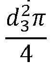
piston 7 result, in the chamber Ch1, from an area Ap1 and pressure pch1 and, in the chamber Ch2, from Ap2 and pressure pch2. The areas are defined in below "Table 1".State 1 is a state when thepiston unit 3 moves toward the chamber Ch1 andstate 2 is a state when thepiston 7 moves towards the chamber Ch2. -
Fig. 3 shows a second embodiment of thefluid cylinder 2 of theactuator system 1 ofFig. 1 . Thefluid cylinder 2 of the second embodiment differs from thefluid cylinder 2 according to the first embodiment in that the inner shape of thefluid cylinder 2 is stepped in the longitudinal direction such that the chamber Ch1 has a sectional diameter d4, whereas, the chamber Ch2 has the sectional diameter d2 which is smaller than the sectional diameter d4. - Furthermore, the
piston 7 of thepiston unit 3 has a shoulder 7' in an axial direction of thepiston 7 adjacent to thepiston rod 8. The shoulder 7' has a sectional diameter d3 which is smaller than the sectional diameter d2 of thepiston 7 but larger than the diameter d1 of thepiston rod 8. - Moreover, the
piston unit 3 of thefluid cylinder 2 according to the second embodiment includes a floatingpiston 10 located in the chamber Ch1. The floatingpiston 10 is formed annular and has an inner diameter d3 and an outer diameter d4. - In this embodiment, the inner chamber of the
fluid cylinder 2 is separated into the first chamber Ch1 and the second chamber Ch2 by thepiston unit 3. The chambers Ch1, Ch2 are formed in a fluid tight manner. - The forces acting to the
piston 7 result, in the chamber Ch1, from the area Ap1 defined in "Table 1" and pressure pch1 and, in the chamber Ch2, from area Ap2 defined in "Table 1" and pressure pch2. -
State 1, referred to in "Table 1", is a state when thepiston 7 is at least partially located in the portion of thefluid cylinder 2 having the sectional diameter d4.State 2, also referred to in "Table 1", is a state when thepiston 7 is completely located in the portion of thefluid cylinder 2 having the sectional diameter d2. - Therefore, in
state 1, the pressure pch1 in the chamber Ch1 acts to thepiston unit 3 via an end face of the shoulder 7', without a sectional area of thepiston rod 8, and via an end face of the floatingpiston 10 abutting to thepiston 7. When thepiston unit 3 moves towardschamber 2 so that the floatingpiston 10 abuts to a step of thefluid cylinder 2 formed by the diameter difference of the diameters d2 and d4, instate 2, the pressure pch1 merely acting to the end face of the shoulder 7' provides a force to thepiston unit 3. Moreover, instate 1 andstate 2, the pressure pch2 is acting to the constant area Ap2. - In the
state 1, thepiston 7 moves together with the floatingpiston 10 and,iny state 2, thepiston 7 moves independently from the floatingpiston 10. -
Fig. 4 shows a third embodiment of thefluid cylinder 2 of theactuator system 1 ofFig. 1 . Thefluid cylinder 2 of the third embodiment differs from thefluid cylinder 2 according to the second embodiment in that the inner shape of thefluid cylinder 2 is stepped in the longitudinal direction such that the chamber Ch1 has a sectional diameter d2, whereas, the chamber Ch2 has the sectional diameter d4 which is larger than the diameter d2. Thepiston 7 having the sectional diameter d2 has the shoulder 7' having the sectional diameter d3 on a side opposite of thepiston rod 8 with respect to thepiston 7. Moreover, the floatingpiston 10 is located in the chamber Ch2. - The forces acting to the
piston 7 result, in the chamber Ch1, from the area Ap1 indicated in "Table 1" and pressure pch1 and, in the chamber Ch2, from Ap2 indicated in "Table 1" and pressure pch2. -
State 2 is a state when thepiston 7 is at least partially located in the portion of thefluid cylinder 2 having the sectional diameter d4, so that the pressure in the chamber Ch2 acts to thepiston 7 via the end face of the shoulder 7' and via the end face of the floatingpiston 10 abutting to thepiston 7. - When the
piston 7 moves towardschamber 1 so that the floatingpiston 10 abuts to a step of thefluid cylinder 2 formed by the diameter difference of the diameters d2 and d4, instate 1, the pressure pch2 merely acting to the end face of the shoulder 7' provides a force to thepiston 7. - In
state 1, thepiston 7 moves independently from the floatingpiston 10 and, instate 2, thepiston 7 moves together with the floatingpiston 10. Moreover, instate 1 andstate 2, the pressure pch1 is acting to the constant area Ap1. -
Fig. 5 shows a fourth embodiment of thefluid cylinder 2 of theactuator system 1 ofFig. 1 . Thefluid cylinder 2 of the fourth embodiment differs from thefluid cylinder 2 according to the second and third embodiment in that the chamber Ch1 and the chamber Ch2 respectively have the sectional diameter d4 and a sectional diameter d5; however, the inner shape of thefluid cylinder 2 is not depicted in a stepped manner in the longitudinal direction so that the diameters d4 and d5 are depicted identically. Moreover, the inner wall of thefluid cylinder 2 is provided with afirst stopper 11 between the chambers Ch1 and Ch2. Furthermore, the sectional diameter d3 of the shoulder 7' and the sectional diameter d2 of thepiston 7 are depicted identically. Thepiston 7 and the shoulder 7' are defined as being separated by asecond stopper 12. This definition is depicted by a dash-and-dot line. - In this fourth embodiment, the
fluid cylinder 2 is provided with a first floatingpiston 10 and a second floating piston 10'. The first floatingpiston 10 is located in the chamber Ch1 and the second floating piston 10' is located in the chamber Ch2. Depending on a direction of the motion of thepiston 7 having the shoulder 7', the two floatingpistons 10, 10' abut to the first orsecond stoppers - In an alternative embodiment, the sectional diameter d2 of the
piston 7 is different from the sectional diameter d3 of the shoulder 7', and the sectional diameters d4 and d5 are different. Also in this alternative embodiment, both chambers Ch1 and Ch2 accommodate one of the floatingpistons 10, 10' and the first floatingpiston 10 in the chamber Ch1 is joined to thepiston 7 in a releasable manner and the second piston 10' in the chamber Ch2 is joined to the shoulder 7' in a releasable manner in order to transmit a force exerted by the respective pressure pch1, pch2 to thepiston 7 or the shoulder 7'. - The forces acting to the
piston 7 result, in the chamber Ch1, from the area Ap1 and pressure pch1 and, in the chamber Ch2, from Ap2 and pressure pch2. The areas are defined in below "Table 1". -
State 1, in this embodiment, is a state when thepiston 7 is completely located in the chamber Ch1 such that the first floatingpiston 10 abuts to thesecond stopper 12 without abutting to thefirst stopper 11. Therefore, the pressure in the chamber Ch1 acts to thepiston unit 3 via the end face of thepiston 7 and via the end face of the first floatingpiston 10 abutting to thesecond stopper 12. Instate 1, in chamber Ch2, the forces result from the pressure pch2 and from the area Ap2 without the end face of the second floating piston 10' since the second floating piston 10' located in the chamber Ch2 abuts to thestopper 11 and does not contribute to a force exerted by the pressure pch2 to thepiston unit 3. - When the
piston unit 3 moves towardschamber 2 so that the first floatingpiston 10 abuts to thestopper 11 of thefluid cylinder 2, the force transmitted by the first floatingpiston 10 to thepiston unit 3 stops and the force is merely exerted by the pressure pch1 acting to the end face of thepiston 7. -
State 2, in this embodiment, is a state when the shoulder 7' is completely located in the chamber Ch2 such that the second floating piston 10' abuts to thesecond stopper 12 without abutting to thefirst stopper 11. Therefore, the pressure in the chamber Ch2 acts to the shoulder 7' via the end face of the shoulder 7' and via the end face of the second floating piston 10' abutting to thesecond stopper 12 joined to thepiston 7. Instate 2, in chamber Ch1, the forces result from the pressure pch1 and from the area Ap1 without the end face of the first floatingpiston 10 since the first floatingpiston 10 located in the chamber Ch1 abuts to thestopper 11 and does not contribute to a force exerted by the pressure pch1 to thepiston unit 3. - When the
piston unit 3 moves towardschamber 1 so that the second floating piston 10' abuts to thestopper 11 of thefluid cylinder 2, the force transmitted by the second floating piston 10' to thepiston unit 3 stops and the force is merely exerted by the pressure pch2 acting to the end face of the shoulder 7'. - The depicted sectional diameters d1 to d5 of the
fluid cylinder 2 and of thepiston unit 3 are nominal dimensions considering necessary clearances for moving the components with respect to one another and necessary piston seals (not shown) as the case may be. - In any embodiments described above, alternatively, the inner shape of the
fluid cylinder 2 and the cross sections of thepiston 7, the shoulder 7', the floatingpistons 10, 10' and thepiston rod 8 of thepiston unit 3 are not circular but have other shapes corresponding to the inner shape of thefluid cylinder 2 and to thepiston rod orifice 9Table 1 Fig 2 .Fig 3 .Fig 4 .Fig 5 .State 1State 2State 1State 2State 1State 2State 1State 2 A p1 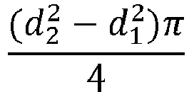


A p2 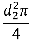



mp m p1 m p1 + m p2 m p1 m p1 m p1 + m p2 m p1 + m p2 m p1 + m p3 - Possible states usv of the
solenoid valves 5 are changed and result in corresponding pressures in the connected chambers according to Table 2.Table 2 Chamber - Ambient pressure Closed chamber Chamber - Supply pressure usv -1 0 1 - Based on a Kalman filter algorithm and on an extended Kalman filter algorithm, methods have been developed to estimate the system states, pressures in the chambers Ch1 and Ch2, temperatures in the chambers Ch1, Ch2, and masses of a fluid. Moreover, a velocity of the
piston 7, an acceleration of thepiston 7, or an actuation force exerted by thepiston 7 which correspond to the respective feature of thepiston unit 3 are estimated based on the position of thepiston 7. In an alternative embodiment, instead of the Kalman filter or of the extended Kalman filter, another control technologic observer model, e.g. a Luenberger observer, can be used. - A state vector, an output vector, and control vectors are defined as in the following (
Expressions 1 to 4):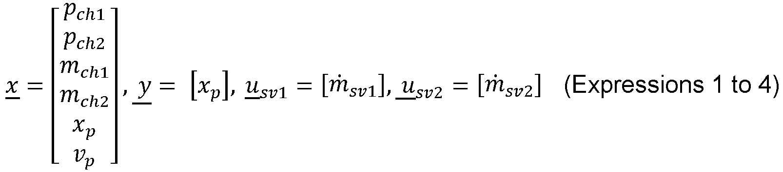
- In these vectors, mch is a mass of the fluid, pch is a pressure of the chamber Ch1, Ch2, xp is the position of the
piston 7, vp is the velocity of thepiston 7, usv is a state of the solenoid valves 5 (see Table 2), and ṁsv is a mass flow rate of thesolenoid valve 5.Subscript 1 refers to the chamber Ch1 andsubscript 2 refers to the chamber Ch2. - The state-space representation is expressed in Expression 5:

- In this state-space representation, n 1 and n 2 are numbers of the
solenoid valves 5 connected to one of the chamber Ch1 and chamber Ch2. Bsv are defined in belowExpression 8, and u sv are indicated in Table 2. - The
fluid cylinder 2 is driven by thesolenoid valves 5 which are "on/off" valves. Alternatively, the fluid cylinder can be driven by proportional valves. If thefluid cylinder 2 is driven by "on/off" valves, the mass flow rate can be estimated according to the Bernoulli expression modified by the solenoid valve state (Expression 6):
- Wherein n is the number of the
solenoid valves 5 connected to one of the chambers Ch1, Ch2, usv is the state of the solenoid valve (see Table 2), αsv is a contraction coefficient of the fluid, and ṁsv is the mass flow rate between connected volumes. - When using the Kalman filter-based method, a linear state-space representation is used, wherein the state and input matrices are as following (
Expression 7, 8):

- Wherein κair is a heat capacity ratio, Fp is a pressure force, Vch is a volume of the chambers Ch1, Ch2, κht is a heat transfer coefficient, Aht is a heat transfer area, ΔT is a temperature difference between the chamber Ch1, Ch2 and an environment, mp is a mass of the
piston 7, and Σ F is a force applied to thepiston 7. - In the case of the extended Kalman filter-based method, as used in the described embodiments, non-linear expressions are used which are defined as following (
Expression 9, 10):

- The Kalman filter-based method and the extended Kalman filter-based method use the state estimation of a previous time step to estimate a current state. Alternatively, the method has another structure.
- The expressions are used for double acting cylinders, however, alternatively, they are used for single acting cylinders.
- The expressions describe a behavior of a
fluid cylinder 2 having a single piston according to the first embodiment of the fluid cylinder 2 (Fig. 2 ). However, alternatively, by changing the parameters of Table 1according to a scheduling signal which is a detected position of thepiston 7, the expressions can be used forfluid cylinders 2 comprising apiston unit 3 having one floatingpiston 10 as in the second and third embodiments (Figs. 3 and 4 ) or two floatingpistons 10, 10' as in the fourth embodiment (Fig. 5 ). - In the following, an example of an estimation of system states of the
fluid cylinder 2 according to the third embodiment (Fig. 4 ) is described. - The
fluid cylinder 2 is actuated by two 3-way 2-position solenoid valves 5 (Fig. 1 ). One of thesolenoid valves 5 is respectively connected to one of the chambers Ch1, Ch2. Alternatively,several solenoid valves 5 are connected to one of the chambers Ch1, Ch2 and the mass flow rates of theseveral solenoid valves 5 connected to one of the Chambers Ch1, Ch2 are summarized to estimate the mass of the fluid. - For performing the example of the estimation with a method for determining the system state of the
fluid cylinder 2 of the actuator system, the position of thepiston 7 of thefluid cylinder 2 is detected, several system states are estimated from the detected position of thepiston 7, and the system state is determined from the several system states. - The system states are chamber pressures of the
fluid cylinder 2 and the position of the piston. In an alternative embodiment, alternatively or additionally, a temperature in the chamber Ch1, Ch2 of thefluid cylinder 2, a mass of the fluid, a piston velocity, an acceleration of thepiston 7, and an actuation force exerted by thepiston 7 are estimated. - The system states are estimated based on the estimated contraction coefficient αsv which is tuned to improve the estimation accuracy. For tuning, the chamber pressure is measured and the contraction coefficient αsv is adapted to minimize a deviation between the estimation and the measurement. Alternatively, the contraction coefficient is not tuned but the contraction coefficient is roughly predetermined for estimating the system states.
- The commands to the
solenoid valves 5 are used as scheduling signals to calculate mass flow rates of the mass of the fluid into or from the chamber Ch1, Ch2 of thefluid cylinder 2 to estimate the mass of the fluid. Alternatively, other signals are used as the scheduling signals. - The system states are estimated based on a friction parameter of the
fluid cylinder 2, and the friction parameter is tuned to improve the estimation accuracy in the current step. For tuning, the piston position is measured and the friction parameter is adapted to minimize a deviation between the estimation and the measurement. Alternatively, the friction parameter is not tuned but a roughly predetermined friction parameter is used for the estimation of the system parameters. - The method for determining the system state of the fluid cylinder is used for synchronization a gearbox during gear change. Alternatively, the method is used another application, e.g., a control of engaging or disengaging a clutch.
- In this example, the
piston 8 is moved from a first situation where thepiston 7 is in a right-hand end position in thecylinder 2 to a second situation of the position of thepiston 7 at a boundary line betweenstate 1 andstate 2 as shown inFig. 4 . - As described above, basically, the floating
piston 10 moves together with thepiston 7 on a first condition and, alternatively, thepiston 7 moves independently from the floatingpiston 10 on a second condition and the system states are estimated depending on the presence of the first or second condition. In this embodiment, the second condition, wherein thepiston 7 moves independently from the floatingpiston 10, exists. - As mentioned above, the commands to the
solenoid valves 5 are used as the scheduling signals, however, alternatively, the detected position of thepiston 3 is used as a scheduling signal for estimating a behavior of thefluid cylinder 2 with a floatingpiston - A predicted state estimate is calculated as following (Expression 11):

-
Fig. 6 shows a result of the estimation of system states performed by the extended Kalman filter. The result refers to the above-mentioned example. - The extended Kalman filer is applied to update the predicted state estimate with the measured position.
- In the uppermost diagram of
Fig. 6 , a command to switch the twosolenoid valves 5 to provide the mass flow of the fluid to the chambers Ch1, Ch2 of thefluid cylinder 2 is output at 26.21 sec. - In the second diagram of
Fig. 6 , the progress of an increase in pressure in the first chamber Ch1 is depicted. A solid line illustrates the progress of measured values for proving the accuracy of the estimation. A dotted line illustrates the progress of estimated values estimated at a clock frequency of 1 ms, a dash-and-dot line illustrates the progress of the estimated values estimated at a clock frequency of 100 µs, and a dashed line illustrates the progress of the estimated values estimated at a clock frequency of 10 µs. The increase in pressure starts with a delay from the switching command to the solenoid valves at about 26.222 sec. - As to be seen from the second diagram of
Fig. 6 , the progress of the increase in pressure in the first chamber Ch1 of the estimated values is slightly below the measured values but it is very well suitable for determining this system state. - In the third diagram of
Fig. 6 , the progress of an increase in pressure in the second chamber Ch2 is depicted. A solid line illustrates the progress of measured values for proving the accuracy of the estimation. A dotted line illustrates the progress of estimated values estimated at a clock frequency of 1 ms, a dash-and-dot line illustrates the progress of the estimated values estimated at a clock frequency of 100 µs, and a dashed line illustrates the progress of the estimated values estimated at a clock frequency of 10 µs. The increase in pressure starts with a delay from the switching command to the solenoid valves at about 26.223 sec. - As to be seen from the third diagram of
Fig. 6 , the progress of the increase in pressure in the second chamber Ch2 of the estimated values is slightly below the measured values but it is very well suitable for determining the this system state. - In the lowermost diagram of
Fig. 6 , the position of thepiston 7 is depicted. A solid line illustrates the measured position. A dotted line illustrates the estimated position estimated at a clock frequency of 1 ms, a dash-and-dot line illustrates the position estimated at a clock frequency of 100 µs, and a dashed line illustrates the position estimated at a clock frequency of 10 µs. A motion of the piston starts with a delay from the switching command to the solenoid valves and the increase in pressure in the first and second chamber Ch1, Ch2 at about 26.23 sec. - As to be seen from
Fig. 6 , the measured position approximately correspond to the estimated values which proves that the extended Kalman filer is very well suitable for estimating the system states. - Although the present invention has been described with reference to specific features and embodiments thereof, it is evident that various modifications and combinations can be made thereto without departing from the scope of the invention defined by the appended claims.
-
- 1
- actuator system
- 2
- fluid cylinder
- 3
- piston unit
- 4
- position sensor
- 5
- solenoid valve
- 6
- Electronic Control Unit (ECU)
- 7
- piston
- 8
- piston rod
- 9
- piston rod orifice
- 10, 10'
- first, second floating piston
- 11
- first stopper
- 12
- second stopper
- Ch1
-
chamber 1 - Ch2
-
chamber 2 - d1 to d5
-
diameter 1 to 5 - EKF
- extended Kalman filter
- SolUp
- solenoid valve up
- SolDown
- solenoid valve down
Claims (12)
- A method for determining a system state of a fluid cylinder (2) of an actuator system (1) comprising the steps:detecting a position of a piston (7) of the fluid cylinder (2); andestimating at least one system state from the detected position of the piston (7),wherein one of the system states is a chamber pressure of the fluid cylinder (2), a temperature in a chamber (Ch1, Ch2) of the fluid cylinder (2), or a mass of a fluid,characterized in thatthe system states are estimated based on an estimated contraction coefficient of the fluid, and the contraction coefficient is tuned to improve estimation accuracy.
- The method of claim 1, wherein
several system states are estimated from the detected position of the piston (7). - The method of claim 1 or 2, wherein
the at least one system state is or the several system states are estimated using a Kalman filter or an extended Kalman filter. - The method of any preceding claim, wherein
a system state estimation of a current time step is performed by using a system state estimation of a previous time step updated by detection data of the detected position of the piston. - The method of any preceding claim, wherein
a command to a solenoid valve (5) is used as scheduling signal to calculate mass flow rates of the mass of the fluid into or from a chamber (Ch1, Ch2) of the fluid cylinder (2) to estimate the mass of the fluid. - The method of claim 5, whereinseveral solenoid valves (5) connected to one chamber (Ch1, Ch2) of the fluid cylinder (2) are used, andthe mass flow rates of the several solenoid valves (5) connected the one chamber (Ch1, Ch2) are summarized to estimate the mass of the fluid.
- The method of any preceding claims, wherein
one of the system states is a piston (7) velocity, an acceleration of the piston (7), or an actuation force exerted by the piston (7). - The method of claim 7, wherein
the system states are estimated based on a friction parameter of the fluid cylinder (2), and the friction parameter is tuned to improve estimation accuracy in the current time step. - The method of claim 7 or 8, whereinthe fluid cylinder (2) comprises a piston (7) and a floating piston (10, 10'),the piston (7) moves together with the floating piston (10, 10') on a first condition, and, alternatively, the piston (7) moves independently from the floating piston (10, 10') on a second condition, andthe system states are estimated depending on the presence of the first or second condition.
- The method of claim 9, wherein
the detected position of the piston (7) is used as a scheduling signal for estimating a behavior of the fluid cylinder (2) with floating pistons (10, 10') on the first or second condition. - A method for determining an actuating force in a fluid driven gear box actuator including the method for determining a system state of a fluid cylinder (2) of anyone of claims 6 to 9, wherein the method for determining the actuating force in the fluid driven gear box actuator is used for synchronization of a gearbox during gear change.
- An actuator system (1), comprisinga fluid cylinder (2) including a piston (7),a position sensor (4) configured to detect a position of the piston (7),a solenoid valve (5) configured to control the fluid cylinder (2), andan Electronic Control Unit (6) configured to determine a system state of the fluid cylinder (2) based on a method according to anyone of claims 1 to 11 whereinthe system states comprise at least one of a chamber pressure of the fluid cylinder (2), a temperature of a chamber (Ch1, Ch2) of the fluid cylinder (2), a mass of a fluid, a velocity of the piston (7), an acceleration of the piston (7), and an actuation force exerted by the piston (7).
Priority Applications (1)
| Application Number | Priority Date | Filing Date | Title |
|---|---|---|---|
| EP19180196.8A EP3751166B1 (en) | 2019-06-14 | 2019-06-14 | Method for determining a system state of a fluid cylinder |
Applications Claiming Priority (1)
| Application Number | Priority Date | Filing Date | Title |
|---|---|---|---|
| EP19180196.8A EP3751166B1 (en) | 2019-06-14 | 2019-06-14 | Method for determining a system state of a fluid cylinder |
Publications (2)
| Publication Number | Publication Date |
|---|---|
| EP3751166A1 EP3751166A1 (en) | 2020-12-16 |
| EP3751166B1 true EP3751166B1 (en) | 2023-08-23 |
Family
ID=67105690
Family Applications (1)
| Application Number | Title | Priority Date | Filing Date |
|---|---|---|---|
| EP19180196.8A Active EP3751166B1 (en) | 2019-06-14 | 2019-06-14 | Method for determining a system state of a fluid cylinder |
Country Status (1)
| Country | Link |
|---|---|
| EP (1) | EP3751166B1 (en) |
Families Citing this family (1)
| Publication number | Priority date | Publication date | Assignee | Title |
|---|---|---|---|---|
| CN118462690A (en) * | 2024-04-29 | 2024-08-09 | 广州粤联科技有限公司 | A real-time adaptive control method and system for hydraulic system working conditions |
Family Cites Families (3)
| Publication number | Priority date | Publication date | Assignee | Title |
|---|---|---|---|---|
| JP3825737B2 (en) * | 2002-10-24 | 2006-09-27 | 住友重機械工業株式会社 | Precision positioning device and processing machine using the same |
| FR3036486B1 (en) * | 2015-05-18 | 2017-05-19 | Sagem Defense Securite | METHOD FOR ESTIMATING AN EXTERNAL FORCE EXERCISING AN ELECTROHYDROSTATIC ACTUATOR |
| JP2017033464A (en) * | 2015-08-05 | 2017-02-09 | 三星電子株式会社Samsung Electronics Co.,Ltd. | State estimation device |
-
2019
- 2019-06-14 EP EP19180196.8A patent/EP3751166B1/en active Active
Also Published As
| Publication number | Publication date |
|---|---|
| EP3751166A1 (en) | 2020-12-16 |
Similar Documents
| Publication | Publication Date | Title |
|---|---|---|
| KR100708948B1 (en) | A method and torque transmission device for operating a vehicle torque transmission device. | |
| US7530262B2 (en) | Method for determining an actuating pressure in an actuating cylinder | |
| US20100305874A1 (en) | Electronic wear state determination in a valve arrangement | |
| CN103975173B (en) | hydraulic operating system | |
| US20090203480A1 (en) | Device for controlling a fluid-activated double-action operating cylinder | |
| US20080275614A1 (en) | Method for determining the clutch application point | |
| US20110168011A1 (en) | Device for controlling the stroke of an actuator | |
| EP3751166B1 (en) | Method for determining a system state of a fluid cylinder | |
| AU2009293815B2 (en) | Flow rate control valve for clutch control device | |
| JP2008232245A (en) | Flow control valve of clutch control device | |
| KR20190057321A (en) | Electrohydraulic system for operating clutches / clutches and gear selector / gear selectors of manual gearboxes | |
| KR960031835A (en) | Control method and apparatus for hydraulic actuating clutch | |
| US7484429B2 (en) | Closed loop adaptive fluid control system and method | |
| CN104685223B (en) | Four-condition fluid cylinder, method of operating the same, and motor vehicle transmission | |
| JP2014509725A (en) | Pneumatic shift stress assist device | |
| US9657788B2 (en) | System and method for the update of fill parameters in wet clutches through cross learning | |
| US9523377B2 (en) | Method for controlling an actuator | |
| US7108632B2 (en) | Control apparatus of automatic transmission | |
| US9611950B2 (en) | Electrohydraulic valve calibration system and method | |
| KR102427703B1 (en) | Clutch control which takes hysteresis into consideration | |
| Song et al. | Automotive transmission clutch fill optimal control: An experimental investigation | |
| CN104930080A (en) | Adaptive control of a linear actuator | |
| US20070130942A1 (en) | Automobile clutch booster | |
| ITMI20012699A1 (en) | CALIBRATION PROCEDURE OF AN AUTOMATED TRANSMISSION SYSTEM WITH A MULTIPLE RATIO TRANSMISSION | |
| EP3255287B1 (en) | Adjustment system for a hydraulic actuator |
Legal Events
| Date | Code | Title | Description |
|---|---|---|---|
| PUAI | Public reference made under article 153(3) epc to a published international application that has entered the european phase |
Free format text: ORIGINAL CODE: 0009012 |
|
| STAA | Information on the status of an ep patent application or granted ep patent |
Free format text: STATUS: THE APPLICATION HAS BEEN PUBLISHED |
|
| AK | Designated contracting states |
Kind code of ref document: A1 Designated state(s): AL AT BE BG CH CY CZ DE DK EE ES FI FR GB GR HR HU IE IS IT LI LT LU LV MC MK MT NL NO PL PT RO RS SE SI SK SM TR |
|
| AX | Request for extension of the european patent |
Extension state: BA ME |
|
| STAA | Information on the status of an ep patent application or granted ep patent |
Free format text: STATUS: REQUEST FOR EXAMINATION WAS MADE |
|
| 17P | Request for examination filed |
Effective date: 20210616 |
|
| RBV | Designated contracting states (corrected) |
Designated state(s): AL AT BE BG CH CY CZ DE DK EE ES FI FR GB GR HR HU IE IS IT LI LT LU LV MC MK MT NL NO PL PT RO RS SE SI SK SM TR |
|
| GRAP | Despatch of communication of intention to grant a patent |
Free format text: ORIGINAL CODE: EPIDOSNIGR1 |
|
| STAA | Information on the status of an ep patent application or granted ep patent |
Free format text: STATUS: GRANT OF PATENT IS INTENDED |
|
| RIC1 | Information provided on ipc code assigned before grant |
Ipc: B60T 7/08 20060101ALI20230224BHEP Ipc: B60T 7/04 20060101ALI20230224BHEP Ipc: F16D 48/02 20060101AFI20230224BHEP |
|
| INTG | Intention to grant announced |
Effective date: 20230321 |
|
| GRAS | Grant fee paid |
Free format text: ORIGINAL CODE: EPIDOSNIGR3 |
|
| GRAA | (expected) grant |
Free format text: ORIGINAL CODE: 0009210 |
|
| STAA | Information on the status of an ep patent application or granted ep patent |
Free format text: STATUS: THE PATENT HAS BEEN GRANTED |
|
| AK | Designated contracting states |
Kind code of ref document: B1 Designated state(s): AL AT BE BG CH CY CZ DE DK EE ES FI FR GB GR HR HU IE IS IT LI LT LU LV MC MK MT NL NO PL PT RO RS SE SI SK SM TR |
|
| REG | Reference to a national code |
Ref country code: GB Ref legal event code: FG4D |
|
| REG | Reference to a national code |
Ref country code: CH Ref legal event code: EP |
|
| REG | Reference to a national code |
Ref country code: DE Ref legal event code: R096 Ref document number: 602019035436 Country of ref document: DE |
|
| REG | Reference to a national code |
Ref country code: IE Ref legal event code: FG4D |
|
| REG | Reference to a national code |
Ref country code: SE Ref legal event code: TRGR |
|
| REG | Reference to a national code |
Ref country code: LT Ref legal event code: MG9D |
|
| REG | Reference to a national code |
Ref country code: NL Ref legal event code: MP Effective date: 20230823 |
|
| REG | Reference to a national code |
Ref country code: AT Ref legal event code: MK05 Ref document number: 1602906 Country of ref document: AT Kind code of ref document: T Effective date: 20230823 |
|
| PG25 | Lapsed in a contracting state [announced via postgrant information from national office to epo] |
Ref country code: GR Free format text: LAPSE BECAUSE OF FAILURE TO SUBMIT A TRANSLATION OF THE DESCRIPTION OR TO PAY THE FEE WITHIN THE PRESCRIBED TIME-LIMIT Effective date: 20231124 |
|
| PG25 | Lapsed in a contracting state [announced via postgrant information from national office to epo] |
Ref country code: IS Free format text: LAPSE BECAUSE OF FAILURE TO SUBMIT A TRANSLATION OF THE DESCRIPTION OR TO PAY THE FEE WITHIN THE PRESCRIBED TIME-LIMIT Effective date: 20231223 |
|
| PG25 | Lapsed in a contracting state [announced via postgrant information from national office to epo] |
Ref country code: RS Free format text: LAPSE BECAUSE OF FAILURE TO SUBMIT A TRANSLATION OF THE DESCRIPTION OR TO PAY THE FEE WITHIN THE PRESCRIBED TIME-LIMIT Effective date: 20230823 Ref country code: PT Free format text: LAPSE BECAUSE OF FAILURE TO SUBMIT A TRANSLATION OF THE DESCRIPTION OR TO PAY THE FEE WITHIN THE PRESCRIBED TIME-LIMIT Effective date: 20231226 Ref country code: NO Free format text: LAPSE BECAUSE OF FAILURE TO SUBMIT A TRANSLATION OF THE DESCRIPTION OR TO PAY THE FEE WITHIN THE PRESCRIBED TIME-LIMIT Effective date: 20231123 Ref country code: NL Free format text: LAPSE BECAUSE OF FAILURE TO SUBMIT A TRANSLATION OF THE DESCRIPTION OR TO PAY THE FEE WITHIN THE PRESCRIBED TIME-LIMIT Effective date: 20230823 Ref country code: LV Free format text: LAPSE BECAUSE OF FAILURE TO SUBMIT A TRANSLATION OF THE DESCRIPTION OR TO PAY THE FEE WITHIN THE PRESCRIBED TIME-LIMIT Effective date: 20230823 Ref country code: LT Free format text: LAPSE BECAUSE OF FAILURE TO SUBMIT A TRANSLATION OF THE DESCRIPTION OR TO PAY THE FEE WITHIN THE PRESCRIBED TIME-LIMIT Effective date: 20230823 Ref country code: IS Free format text: LAPSE BECAUSE OF FAILURE TO SUBMIT A TRANSLATION OF THE DESCRIPTION OR TO PAY THE FEE WITHIN THE PRESCRIBED TIME-LIMIT Effective date: 20231223 Ref country code: HR Free format text: LAPSE BECAUSE OF FAILURE TO SUBMIT A TRANSLATION OF THE DESCRIPTION OR TO PAY THE FEE WITHIN THE PRESCRIBED TIME-LIMIT Effective date: 20230823 Ref country code: GR Free format text: LAPSE BECAUSE OF FAILURE TO SUBMIT A TRANSLATION OF THE DESCRIPTION OR TO PAY THE FEE WITHIN THE PRESCRIBED TIME-LIMIT Effective date: 20231124 Ref country code: FI Free format text: LAPSE BECAUSE OF FAILURE TO SUBMIT A TRANSLATION OF THE DESCRIPTION OR TO PAY THE FEE WITHIN THE PRESCRIBED TIME-LIMIT Effective date: 20230823 Ref country code: AT Free format text: LAPSE BECAUSE OF FAILURE TO SUBMIT A TRANSLATION OF THE DESCRIPTION OR TO PAY THE FEE WITHIN THE PRESCRIBED TIME-LIMIT Effective date: 20230823 |
|
| P01 | Opt-out of the competence of the unified patent court (upc) registered |
Effective date: 20240105 |
|
| PG25 | Lapsed in a contracting state [announced via postgrant information from national office to epo] |
Ref country code: PL Free format text: LAPSE BECAUSE OF FAILURE TO SUBMIT A TRANSLATION OF THE DESCRIPTION OR TO PAY THE FEE WITHIN THE PRESCRIBED TIME-LIMIT Effective date: 20230823 |
|
| PG25 | Lapsed in a contracting state [announced via postgrant information from national office to epo] |
Ref country code: ES Free format text: LAPSE BECAUSE OF FAILURE TO SUBMIT A TRANSLATION OF THE DESCRIPTION OR TO PAY THE FEE WITHIN THE PRESCRIBED TIME-LIMIT Effective date: 20230823 |
|
| PG25 | Lapsed in a contracting state [announced via postgrant information from national office to epo] |
Ref country code: SM Free format text: LAPSE BECAUSE OF FAILURE TO SUBMIT A TRANSLATION OF THE DESCRIPTION OR TO PAY THE FEE WITHIN THE PRESCRIBED TIME-LIMIT Effective date: 20230823 Ref country code: RO Free format text: LAPSE BECAUSE OF FAILURE TO SUBMIT A TRANSLATION OF THE DESCRIPTION OR TO PAY THE FEE WITHIN THE PRESCRIBED TIME-LIMIT Effective date: 20230823 Ref country code: ES Free format text: LAPSE BECAUSE OF FAILURE TO SUBMIT A TRANSLATION OF THE DESCRIPTION OR TO PAY THE FEE WITHIN THE PRESCRIBED TIME-LIMIT Effective date: 20230823 Ref country code: EE Free format text: LAPSE BECAUSE OF FAILURE TO SUBMIT A TRANSLATION OF THE DESCRIPTION OR TO PAY THE FEE WITHIN THE PRESCRIBED TIME-LIMIT Effective date: 20230823 Ref country code: DK Free format text: LAPSE BECAUSE OF FAILURE TO SUBMIT A TRANSLATION OF THE DESCRIPTION OR TO PAY THE FEE WITHIN THE PRESCRIBED TIME-LIMIT Effective date: 20230823 Ref country code: CZ Free format text: LAPSE BECAUSE OF FAILURE TO SUBMIT A TRANSLATION OF THE DESCRIPTION OR TO PAY THE FEE WITHIN THE PRESCRIBED TIME-LIMIT Effective date: 20230823 Ref country code: SK Free format text: LAPSE BECAUSE OF FAILURE TO SUBMIT A TRANSLATION OF THE DESCRIPTION OR TO PAY THE FEE WITHIN THE PRESCRIBED TIME-LIMIT Effective date: 20230823 |
|
| REG | Reference to a national code |
Ref country code: DE Ref legal event code: R097 Ref document number: 602019035436 Country of ref document: DE |
|
| PG25 | Lapsed in a contracting state [announced via postgrant information from national office to epo] |
Ref country code: IT Free format text: LAPSE BECAUSE OF FAILURE TO SUBMIT A TRANSLATION OF THE DESCRIPTION OR TO PAY THE FEE WITHIN THE PRESCRIBED TIME-LIMIT Effective date: 20230823 |
|
| PLBE | No opposition filed within time limit |
Free format text: ORIGINAL CODE: 0009261 |
|
| STAA | Information on the status of an ep patent application or granted ep patent |
Free format text: STATUS: NO OPPOSITION FILED WITHIN TIME LIMIT |
|
| 26N | No opposition filed |
Effective date: 20240524 |
|
| PG25 | Lapsed in a contracting state [announced via postgrant information from national office to epo] |
Ref country code: SI Free format text: LAPSE BECAUSE OF FAILURE TO SUBMIT A TRANSLATION OF THE DESCRIPTION OR TO PAY THE FEE WITHIN THE PRESCRIBED TIME-LIMIT Effective date: 20230823 |
|
| PG25 | Lapsed in a contracting state [announced via postgrant information from national office to epo] |
Ref country code: BG Free format text: LAPSE BECAUSE OF FAILURE TO SUBMIT A TRANSLATION OF THE DESCRIPTION OR TO PAY THE FEE WITHIN THE PRESCRIBED TIME-LIMIT Effective date: 20230823 |
|
| PG25 | Lapsed in a contracting state [announced via postgrant information from national office to epo] |
Ref country code: BG Free format text: LAPSE BECAUSE OF FAILURE TO SUBMIT A TRANSLATION OF THE DESCRIPTION OR TO PAY THE FEE WITHIN THE PRESCRIBED TIME-LIMIT Effective date: 20230823 |
|
| PG25 | Lapsed in a contracting state [announced via postgrant information from national office to epo] |
Ref country code: MC Free format text: LAPSE BECAUSE OF FAILURE TO SUBMIT A TRANSLATION OF THE DESCRIPTION OR TO PAY THE FEE WITHIN THE PRESCRIBED TIME-LIMIT Effective date: 20230823 |
|
| REG | Reference to a national code |
Ref country code: CH Ref legal event code: PL |
|
| PG25 | Lapsed in a contracting state [announced via postgrant information from national office to epo] |
Ref country code: LU Free format text: LAPSE BECAUSE OF NON-PAYMENT OF DUE FEES Effective date: 20240614 |
|
| GBPC | Gb: european patent ceased through non-payment of renewal fee |
Effective date: 20240614 |
|
| PG25 | Lapsed in a contracting state [announced via postgrant information from national office to epo] |
Ref country code: IE Free format text: LAPSE BECAUSE OF NON-PAYMENT OF DUE FEES Effective date: 20240614 |
|
| PG25 | Lapsed in a contracting state [announced via postgrant information from national office to epo] |
Ref country code: BE Free format text: LAPSE BECAUSE OF NON-PAYMENT OF DUE FEES Effective date: 20240630 Ref country code: CH Free format text: LAPSE BECAUSE OF NON-PAYMENT OF DUE FEES Effective date: 20240630 |
|
| PG25 | Lapsed in a contracting state [announced via postgrant information from national office to epo] |
Ref country code: FR Free format text: LAPSE BECAUSE OF NON-PAYMENT OF DUE FEES Effective date: 20240630 |
|
| PG25 | Lapsed in a contracting state [announced via postgrant information from national office to epo] |
Ref country code: GB Free format text: LAPSE BECAUSE OF NON-PAYMENT OF DUE FEES Effective date: 20240614 |
|
| REG | Reference to a national code |
Ref country code: BE Ref legal event code: MM Effective date: 20240630 |
|
| PGFP | Annual fee paid to national office [announced via postgrant information from national office to epo] |
Ref country code: DE Payment date: 20250626 Year of fee payment: 7 |
|
| PGFP | Annual fee paid to national office [announced via postgrant information from national office to epo] |
Ref country code: SE Payment date: 20250619 Year of fee payment: 7 |
|
| PG25 | Lapsed in a contracting state [announced via postgrant information from national office to epo] |
Ref country code: CY Free format text: LAPSE BECAUSE OF FAILURE TO SUBMIT A TRANSLATION OF THE DESCRIPTION OR TO PAY THE FEE WITHIN THE PRESCRIBED TIME-LIMIT; INVALID AB INITIO Effective date: 20190614 |
|
| PG25 | Lapsed in a contracting state [announced via postgrant information from national office to epo] |
Ref country code: HU Free format text: LAPSE BECAUSE OF FAILURE TO SUBMIT A TRANSLATION OF THE DESCRIPTION OR TO PAY THE FEE WITHIN THE PRESCRIBED TIME-LIMIT; INVALID AB INITIO Effective date: 20190614 |