EP3751093A1 - Crushing method and depressurizing device used for same - Google Patents
Crushing method and depressurizing device used for same Download PDFInfo
- Publication number
- EP3751093A1 EP3751093A1 EP19748135.1A EP19748135A EP3751093A1 EP 3751093 A1 EP3751093 A1 EP 3751093A1 EP 19748135 A EP19748135 A EP 19748135A EP 3751093 A1 EP3751093 A1 EP 3751093A1
- Authority
- EP
- European Patent Office
- Prior art keywords
- flow path
- well
- depressurizing device
- depressurizing
- bedrock
- Prior art date
- Legal status (The legal status is an assumption and is not a legal conclusion. Google has not performed a legal analysis and makes no representation as to the accuracy of the status listed.)
- Granted
Links
Images





Classifications
-
- E—FIXED CONSTRUCTIONS
- E21—EARTH OR ROCK DRILLING; MINING
- E21B—EARTH OR ROCK DRILLING; OBTAINING OIL, GAS, WATER, SOLUBLE OR MELTABLE MATERIALS OR A SLURRY OF MINERALS FROM WELLS
- E21B43/00—Methods or apparatus for obtaining oil, gas, water, soluble or meltable materials or a slurry of minerals from wells
- E21B43/25—Methods for stimulating production
- E21B43/26—Methods for stimulating production by forming crevices or fractures
-
- E—FIXED CONSTRUCTIONS
- E21—EARTH OR ROCK DRILLING; MINING
- E21B—EARTH OR ROCK DRILLING; OBTAINING OIL, GAS, WATER, SOLUBLE OR MELTABLE MATERIALS OR A SLURRY OF MINERALS FROM WELLS
- E21B34/00—Valve arrangements for boreholes or wells
- E21B34/06—Valve arrangements for boreholes or wells in wells
- E21B34/10—Valve arrangements for boreholes or wells in wells operated by control fluid supplied from outside the borehole
- E21B34/102—Valve arrangements for boreholes or wells in wells operated by control fluid supplied from outside the borehole with means for locking the closing element in open or closed position
- E21B34/103—Valve arrangements for boreholes or wells in wells operated by control fluid supplied from outside the borehole with means for locking the closing element in open or closed position with a shear pin
-
- E—FIXED CONSTRUCTIONS
- E21—EARTH OR ROCK DRILLING; MINING
- E21B—EARTH OR ROCK DRILLING; OBTAINING OIL, GAS, WATER, SOLUBLE OR MELTABLE MATERIALS OR A SLURRY OF MINERALS FROM WELLS
- E21B33/00—Sealing or packing boreholes or wells
- E21B33/10—Sealing or packing boreholes or wells in the borehole
- E21B33/12—Packers; Plugs
-
- E—FIXED CONSTRUCTIONS
- E21—EARTH OR ROCK DRILLING; MINING
- E21B—EARTH OR ROCK DRILLING; OBTAINING OIL, GAS, WATER, SOLUBLE OR MELTABLE MATERIALS OR A SLURRY OF MINERALS FROM WELLS
- E21B34/00—Valve arrangements for boreholes or wells
- E21B34/06—Valve arrangements for boreholes or wells in wells
- E21B34/12—Valve arrangements for boreholes or wells in wells operated by movement of casings or tubings
-
- E—FIXED CONSTRUCTIONS
- E21—EARTH OR ROCK DRILLING; MINING
- E21B—EARTH OR ROCK DRILLING; OBTAINING OIL, GAS, WATER, SOLUBLE OR MELTABLE MATERIALS OR A SLURRY OF MINERALS FROM WELLS
- E21B34/00—Valve arrangements for boreholes or wells
- E21B34/16—Control means therefor being outside the borehole
Definitions
- the present invention relates to a fracturing method that is used to fracture bedrock, and a depressurizing device that is used for the same.
- Geothermal power generation uses geofluids to generate electricity. Geofluid regions currently used for power generation are equal to or lower than the critical point of pure water (374°C and 22 MPa). Envisaging the future, supercritical geothermal power generation to utilize supercritical fluids (fluids at or above the critical point) that are present in places beyond the regions currently used, for geothermal power generation, is under research.
- the use of supercritical fluids for geothermal power generation provides an advantage of increasing specific enthalpy. For example, the specific enthalpy of the liquid-phase of saturated water vapor pressure (about 4 MPa) at 250°C is approximately 1000 kJ/kg, and the specific enthalpy of heated steam at 400°C is approximately 3000 kJ/kg.
- This hydraulic fracturing method refers to a method of causing cracks in bedrock by injecting a fracturing fluid, such as water filled in a well, in the bedrock at high pressure.
- a crack support material referred to as a "proppant”
- a fracturing fluid in which a granular material such as sand is added as a proppant, is injected at high pressure.
- a fracturing fluid containing a hydrolysable blocking agent for blocking hydrolysable materials that temporarily seal cracks is injected at high pressure.
- Patent Literature 1 According to the conventional hydraulic fracturing method and the mining method disclosed in Patent Literature 1, it is possible to improve the permeability (transparency) of bedrock and collect underground resources effectively, by injecting a fracturing fluid at high pressure to cause cracks in the bedrock.
- Patent Literature 1 Japanese Unexamined Patent Application Publication No. 2016-098503
- the brittleness of the crust - that is, the shear strength of bedrock - increases as the depth increases.
- Such changes in strength follow the so-called law of friction.
- up to a certain depth is the brittle range of bedrock, which can be destroyed by applying force to the bedrock.
- a certain depth and below is the ductile range of bedrock, which can be deformed by applying force to the bedrock.
- the above-described conventional hydraulic fracturing method and the method disclosed in Patent Literature 1 inject a fracturing fluid at high pressure, in order to improve the permeability of bedrock, and therefore are applicable to the brittle range of bedrock, which can be destroyed by applying force. That is, even if a fracturing fluid is injected in the ductile range of bedrock where a supercritical fluid is present, it is still not possible to cause cracks in the ductile range of bedrock, and, as a result of this, the permeability of bedrock cannot be improved. Therefore, the conventional hydraulic fracturing method and the mining method disclosed in Patent Literature 1 cannot be applied to the ductile range of bedrock.
- the present invention has been made in view of the above-described problems, and it is therefore an object of the present invention to provide a fracturing method that can cause cracks even in the ductile range of bedrock, and a depressurizing device that is used for this.
- the fracturing method according to a first invention which is used to cause a crack in bedrock, includes an installation step of installing, in a well installed in the bedrock, a depressurizing device, which depressurizes the inside of the well, and a depressurization step of depressurizing the inside of the well, with the depressurizing device installed in the installation step.
- the installation step includes installing, in the well, a connecting pipe, which is connected to the depressurizing device, and a packer, which is attached to the connecting pipe, and the depressurization step includes shutting off a gap between the well and the connecting pipe, with the packer, and depressurizing a region in the well below the packer, with the depressurizing device.
- the installation step includes installing the depressurizing device including a flow path, in which a fluid travels, and a switching mechanism, which switches between opening and closing the flow path, in the well with the flow path closed, and the depressurization step includes depressurizing the inside of the well by switching the switching mechanism and opening up the flow path that is closed.
- the installation step includes installing, in the well, the depressurizing device including the flow path, which includes a first flow path, which is connected to a connecting pipe, to which a packer that shuts off the well is attached, and a second flow path, which is coupled to the first flow path, so as to be able to move in a relative manner, a closing unit, which closes the flow path, and the switching mechanism, which includes a locking unit, which locks the closing unit, and the depressurization step includes depressurizing the inside of the well by moving the first flow path and the second flow path relative to each other, and opening up the flow path closed with the closing unit locked by the locking unit.
- the depressurization step includes depressurizing the inside of the well, installed in the bedrock containing a fluid in a supercritical state or a subcritical state.
- the depressurizing device is a depressurizing device used in the fracturing method according to any one of the first invention to the fifth invention, and depressurizes the inside of the well.
- the depressurizing device includes a flow path, in which a fluid travels, and a switching mechanism, which switches between opening and closing the flow path.
- the fracturing method according to the present invention includes a depressurization step of depressurizing the inside of a well by means of a depressurizing device.
- the depressurizing device depressurizes the inside of a well.
- a high-temperature and high-pressure fluid in a supercritical state or a subcritical state is depressurized and boiled. Consequently, with the depressurizing device according to the present invention, bedrock is cooled quickly by the latent heat of vaporization during the depressurization and boiling, so that it is possible to cause cracks in the bedrock by using the difference in thermal stress between the quickly cooled part and the other parts.
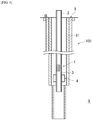
- FIG. 1 is a diagram to show a fracturing system 100 that is used in the fracturing method according to the present invention.
- the fracturing system 100 is used for the fracturing method according to the present invention, and used to cause cracks in a bedrock 9 near the bottom of a well 8.
- the fracturing system 100 is installed inside the well 8.
- a plurality of casing pipes 81 are installed inside the well 8.
- the bedrock 9 near the bottom of the well 8 is the ductile range, and contains a high-temperature and high-pressure fluid in a supercritical state or a subcritical state.
- the fluid contained in the bedrock 9 include, for example, water, carbon dioxide, oil, natural gas, shale gas, and so forth.
- the length of the well 8 depends on the bedrock 9 to be installed, and is 3 km or more, for example.
- the fracturing system 100 includes a depressurizing device 1 according to the present invention, a pipe body 2, a connecting pipe 3, and a packer 4.
- the depressurizing device 1 depressurizes the inside of the well 8.
- the depressurizing device 1 has the pipe body 2 connected to its upper-end side, and has the connecting pipe 3 connected to its lower-end side. Note that the connecting pipe 3 connected with the pipe body 2 may be connected to the upper-end side of the depressurizing device 1.
- a number of tubular members such as steel pipes and drill pipes are coupled to the pipe body 2.
- the pipe body 2 is inserted in the casing pipe 81 of the well 8, and extends from near the ground to near the bottom of the well 8.
- the connecting pipe 3 is a tubular member made of metal or the like, around which the packer 4 is attached.
- the packer 4 expands by means of a predetermined mechanism, to shut off the gap (annulus part) between the casing pipe 81 of the well 8 and the connecting pipe 3.
- a packer 4 made of resin or metal is used.
- the packer 4 may be filled with an enclosed liquid such as water inside, and expand by the thermal expansion of the enclosed liquid.
- the packer 4 filled with the enclosed liquid can be used even if the temperature of the bedrock 9 is 374°C or higher, which is the critical point of water.
- connecting pipe 3 and the packer 4 are arranged on the lower side of the depressurizing device 1 in the example shown in FIG. 1 , they may be arranged on the upper side of the depressurizing device 1.
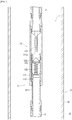
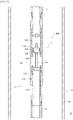
- FIG. 2 is a diagram to primarily show the first embodiment of the depressurizing device 1 according to the present invention.
- the depressurizing device 1 according to the first embodiment has a cylindrical flow path 11, in which a fluid travels, and a switching mechanism 12, which switches between opening and closing the flow path 11.
- the flow path 11 has a first tubular flow path 111, which is connected to the connecting pipe 3 side, and a cylindrical second flow path 112, which is connected to the pipe body 2 side.
- the first flow path 111 is arranged below the second flow path 112, and inserted in the second flow path 112.
- the first flow path 111 and the second flow path 112 are coupled with each other via a first coupling unit 113 using a shear pin or the like. By unbinding the first coupling unit 113, the first flow path 111 and the second flow path 112 are decoupled, and the first flow path 111 and the second flow path 112 can move in a relative manner.
- the switching mechanism 12 has a rod-shaped contact unit 121, which is fixed to the second flow path 112, an elastic unit 122, which is attached to the first flow path 111, a closing unit 123, which is attached to the upper end of the elastic unit 122 to close the flow path 11, and a locking unit 124, which locks the closing unit 123.
- a recessed unit 121a which is recessed in a conical shape or the like, is formed at the lower end of the contact unit 121.
- a stretchable elastic member such as a spring is used as the elastic unit 122.
- the elastic unit 122 is attached to the first flow path 111 so as to be stretchable in the direction in which the first flow path 111 extends.
- the locking unit 124 is formed in the first flow path 111 so that the upper-end side of the first flow path 111 is reduced in diameter than the other parts of the first flow path.
- the closing unit 123 is locked by the locking unit 124 to close the flow path 11.
- the closing unit 123 is shaped so that the upper end thereof can mate with the recessed unit 121a of the contact unit 121, and is formed, for example, in a conical shape.
- FIG. 3 is a diagram to show a well 8 at the beginning of the fracturing method according to the present invention.
- the fracturing method according to the present invention is first started in a state in which the excavation of the well 8 has been completed.
- a number of casing pipes 81 are coupled to the well 8.
- the bedrock 9 near the bottom of the well 8 is the ductile range, and contains a high-temperature and high-pressure fluid in a supercritical state or a subcritical state.
- the fracturing method according to the present invention includes an installation step and a depressurization step.
- FIG. 4 is a diagram to show the installation step in the fracturing method according to the present invention.
- FIG. 5 is a diagram to primarily show the depressurizing device 1 according to the first embodiment in the installation step.
- a fracturing system 100 which includes the depressurizing device 1, a pipe body 2, a connecting pipe 3 and a packer 4, is descended to near the bottom of well 8 and installed in the well 8.
- the bedrock 9 around the packer 4 installed inside the well 8 contains a high-temperature and high-pressure fluid in a supercritical state or a subcritical state.
- a flow path 11 of the depressurizing device 1 is installed inside the well 8 while being closed with the closing unit 123.
- the pressure inside the flow path 11 (first flow path 111) below the closing unit 123 is made higher, by a high-temperature and high-pressure fluid in a supercritical state or a subcritical state, than the pressure inside the flow path 11 (second flow path 112) on the higher side over the closing unit 123.
- the first flow path 111 and the second flow path 112 are coupled with each other via the first coupling unit 113.
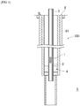
- FIG. 6 is a diagram to show the fracturing system in which the gap between the well 8 and the connecting pipe 3 is shut off with the packer 4 in the depressurization step.
- the packer 4 installed is expanded.
- the expanded packer 4 shuts off the gap between the casing pipe 81 of the well 8 and the connecting pipe 3. That is, in the depressurization step, the packer 4 is expanded to divide the inside of the well 8 into a region above the packer 4 and a region below the packer 4.
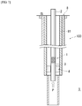
- FIG. 7 is a diagram to show the fracturing system 100 when the depressurizing device 1 carries out depressurization in the depressurization step.
- FIG. 8 is a diagram to primarily show the depressurizing device 1 of FIG. 7 .
- the first coupling unit 113 which couples the first flow path 111 and the second flow path 11, is unbound, and the second flow path 112 is moved downward with respect to the first flow path 111. Since the gap between the casing pipe 81 of the well 8 and the connecting pipe 3 is shut off with the packer 4, the position of the connecting pipe 3 is fixed. Therefore, the position of the first flow path 111 that is connected with the connecting pipe 3 is also fixed. Therefore, by applying a downward force to the second flow path 112, it is possible to unbind the first coupling unit 113, and push downward and move the second flow path 112 with respect to the first flow path 111. By moving the second flow path 112 downward, the contact unit 121 of the switching mechanism 12 is brought into contact with the closing unit 123. At this time, the recessed unit 121a of the contact unit 121 fits on the upper end of the closing unit 123.
- the elastic unit 122 is deformed so as to contract via the closing unit 123 that is in contact with the contact unit 121.
- the closing unit 123 locked by the locking unit 124 is unlocked, and a gap is created between the closing unit 123 and the first flow path 111.
- the flow path 11, which has been closed with the closing unit 123 is opened up. In this way, the closed flow path 11 is switched by the switching mechanism 12, and the flow path 11 is opened up.
- the inside of the well 8 is depressurized by means of the depressurizing device 1, so that the high-temperature and high-pressure fluid contained in the bedrock 9 in a supercritical state or a subcritical state is depressurized and boiled. Consequently, the bedrock 9 is quickly cooled by the latent heat of vaporization during the depressurization and boiling, so that it is possible to cause cracks in the bedrock 9 by using the difference in thermal stress between the quickly cooled part and the other parts.
- FIG. 9 is a diagram to show the fracturing system 100 at the end of the depressurization step.
- the fluid that has flown into the flow path 11 also flows into the pipe body 2, and the pipe body 2 is filled with the fluid.
- the expanded packer 4 is contracted so as to open up the gap between the casing pipe 81 of the well 8 and the connecting pipe 3 that has been shut off.
- the depressurizing device 1, the pipe body 2, the connecting pipe 3 and the packer 4 are taken out of the well 8, and the fluid filled in the pipe body 2 is collected.
- the installation step and the depressurization step are newly carried out.
- the first coupling unit 113 which is already unbound, is replaced with a new first coupling unit 113 that is not unbound, and the first flow path 111 and the second flow path 112 are coupled in advance.
- the installation step and the depressurization step are carried out a number of times, and the fracturing method according to the present invention is completed.
- the fracturing method according to the present invention includes a depressurization step of depressurizing the inside of a well 8 by means of a depressurizing device 1.
- a high-temperature and high-pressure fluid in a supercritical state or a subcritical state is depressurized and boiled. Therefore, with the fracturing method according to the present invention, bedrock 9 is cooled quickly by the latent heat of vaporization during the depressurization and boiling, so that it is possible to cause cracks in the bedrock 9 by using the difference in thermal stress between the quickly cooled part and the other parts.
- fracturing method according to the present invention unlike conventional hydraulic fracturing methods, a fracturing fluid is not injected in the bedrock 9 at high pressure. Therefore, no equipment for applying high pressure is required, so that it is possible to reduce the cost.
- the fracturing method according to the present invention does not require the fracturing fluid itself. Consequently, it is possible to prevent the surrounding water resources from running out, and reduce the burden on the environment.
- the depressurizing device 1 in which the flow path 11 is closed, is installed inside the well 8, and, in the depressurization step, the switching mechanism 12 is switched to open up the closed flow path 11, thereby depressurizing the inside of the well 8.
- the connecting pipe 3 that is connected to the depressurizing device 1 and the packer 4 that is arranged around the connecting pipe 3 are disposed inside the well 8, and, in the depressurization step, the gap between the well 8 and the connecting pipe 3 is shut off with the packer 4, and the region inside the well 8 below the packer 4 is depressurized by means of the depressurizing device 1.
- the fracturing method according to the present invention it is possible to prevent the fluid from leaking from the gap between the casing pipe 81 of the well 8 and the connecting pipe 3, which is shut off with the packer 4. Consequently, it is possible to allow the fluid to flow into the connecting pipe 3, reliably, and depressurize the inside of the well 8 effectively.
- the fluid that has flown in from the connecting pipe 3 is allowed to flow into the pipe body 2 via the flow path 11.
- the bedrock 9 near the well 8 that is depressurized in the depressurization step contains a fluid in a supercritical state or a subcritical state.
- the fluid has a high specific enthalpy, so that this fluid can be used, suitably, for supercritical geothermal power generation.
- the depressurizing device 1 according to the present invention depressurizes the inside of the well 8.
- a high-temperature and high-pressure fluid in a supercritical state or a subcritical state is depressurized and boiled. Consequently, with the depressurizing device 1 according to the present invention, bedrock 9 is cooled quickly by the latent heat of vaporization during the depressurization and boiling, so that it is possible to cause cracks in the bedrock 9 by using the difference in thermal stress between the quickly cooled part and the other parts.
- the depressurizing device 1 includes a flow path 11, in which the fluid contained in the bedrock 9 travels, and a switching mechanism 12, which switches between opening and closing the flow path 11.
- the depressurizing device 1 according to the present invention can depressurize the inside of the well 8, simply by switching the switching mechanism 12. That is, the pressure inside the well 8 can be reduced easily.
- the depressurizing device 1 With the depressurizing device 1 according to the present invention, the connecting pipe 3, around which the packer 4 is attached, is connected to the flow path 11.
- the depressurizing device 1 according to the present invention can prevent the fluid from leaking from the gap between the casing pipe 81 and the connecting pipe 3. Consequently, it is possible to allow the fluid to flow into the connecting pipe 3, reliably, and depressurize the inside of the well 8 effectively.
- the connecting pipe 3 and the pipe body 2 are connected to the flow path 11.
- the fluid that has flown in from the connecting pipe 3 is allowed to flow into the pipe body 2 via the flow path 11. Consequently, the fluid can be collected effectively.
- the flow path 11 has a first flow path 111, which is connected to a connecting pipe 3, and a second flow path 112, which is coupled so as to be able to move relative to the first flow path 111, and the switching mechanism 12 has a closing unit 123, which closes the flow path 11, and a locking unit 124, which locks the closing unit 123, and, by allowing the first flow path 111 and the second flow path 112 to move relatively, the closing unit 123, locked by the locking unit 124, is unlocked, and the flow path 11 is opened up.
- the flow path 11 that is closed can be opened up simply by moving the first flow path 111 and the second flow path 112. Consequently, with the depressurizing device 1 according to the present invention, the inside of the well 8 can be depressurized simply by allowing the first flow path 111 and the second flow path 112 to move relatively. That is, the inside of the well 8 can be depressurized even more easily.
- the first flow path 111 and the second flow path 112 are coupled via the first coupling unit 113, and, by unbinding this first coupling unit 113, the first flow path 111 and the second flow path 112 can move in a relative manner.
- the inside of the well 8 can be depressurized at any position.
- the depressurizing device 1 according to the present invention has a closing unit 123, which is formed in a shape that can mate with the contact unit 121.
- the closing unit 123 mates with the contact unit 121 when the closing unit 123 contacts the contact unit 121. Therefore, even if the fluid travels in the flow path 11, the closing unit 123 can be kept in a stable state. As a result of this, it is possible to maintain the state in which the flow path 11 is open.
- FIG. 10 is a diagram to primarily show the second embodiment of the depressurizing device 1 according to the present invention.
- the depressurizing device 1 according to the second embodiment includes, as shown in FIG. 10 , a cylindrical flow path 11, in which the fluid contained in bedrock 9 travels, and a switching mechanism 15 for switching between opening and closing the flow path 11.
- the switching mechanism 15 has a contact unit 151 of a rod shape, which is fixed to the first flow path 111, a cylindrical fixing unit 152, which is fixed inside the second flow path 112, a closing unit 153, which closes the flow path 11, and a locking unit 154, which locks the closing unit 153.
- the fixing unit 152 and the closing unit 153 are coupled with each other, via the second coupling unit 155 using a shear pin or the like. By unbinding the second coupling unit 155, the fixing unit 152 and the closing unit 153 are decoupled, so that the fixing unit 152 and the closing unit 153 can move in a relative manner.
- the fixing unit 152 has, on its lower-end side, a locking unit 154, which is formed to have a smaller diameter than the other parts. In the example illustrated, the locking unit 154 and the closing unit 153 formed in the fixing unit 152 are coupled with each other via the second coupling unit 155.
- the closing unit 153 is locked by the locking unit 154 to close the flow path 11.
- the fracturing method according to the present invention includes an installation step and a depressurization step.
- the first flow path 111 and the second flow path 112 are coupled with each other via the first coupling unit 113.
- the fixing unit 152 and the closing unit 153 are coupled with each other, via the second coupling unit 155. The rest is the same as in the installation step described above, and therefore the description thereof will be omitted.
- the depressurization step is performed.
- the packer 4 installed is expanded.
- the expanded packer 4 shuts off the gap between the casing pipe 81 of the well 8 and the connecting pipe 3.
- FIG. 11 is a diagram to primarily show the depressurizing device 1, in which a first flow path 111 and a second flow path 112 are decoupled in the depressurization step.
- the first coupling unit 113 which couples the first flow path 111 and the second flow path 112 is unbound, and the second flow path 112 is moved downward with respect to the first flow path 111. Since the gap between the casing pipe 81 of the well 8 and the connecting pipe 3 is shut off with the packer 4, the position of the connecting pipe 3 is fixed. Therefore, the position of the first flow path 111 that is connected with the connecting pipe 3 is also fixed.
- FIG. 12 is a diagram to primarily show the depressurizing device 1 in which the fixing unit 152 and the closing unit 153 are decoupled in the depressurization step.
- the closing unit 153 of the switching mechanism 15 contacts the contact unit 151, the position of the closing unit 153 is fixed. Consequently, by applying a downward force to the second flow path 112 more, it is possible to unbind the second coupling unit 155, which couples the fixing unit 152 and the closing unit 153 fixed to the second flow path 112, and move the second flow path 112 further downward with respect to the first flow path 111.
- the closing unit 153 By moving the second flow path 112 further downward, the closing unit 153, locked by the locking unit 154, is unlocked, and a gap is created between the closing unit 153 and the fixing unit 152. As a result of this, the flow path 11 that is closed with the closing unit 153 is opened up. In this way, the closed flow path 11 is switched by the switching mechanism 15, and the flow path 11 is opened up.
- the inside of the well 8 is depressurized by means of the depressurizing device 1, so that the high-temperature and high-pressure fluid contained in the bedrock 9 in a supercritical state or a subcritical state is depressurized and boiled. Consequently, the bedrock 9 is quickly cooled by the latent heat of vaporization during the depressurization and boiling, so that it is possible to cause cracks in the bedrock 9 by using the difference in thermal stress between the quickly cooled part and the other parts.
- the fluid that has flown into the flow path 11 also flows into the pipe body 2, and the pipe body 2 is filled with the fluid.
- the expanded packer 4 is contracted so as to open up the gap between the casing pipe 81 of the well 8 and the connecting pipe 3 that has been shut off.
- the depressurizing device 1, the pipe body 2, the connecting pipe 3 and the packer 4 are taken out of the well 8, and the fluid filled in the pipe body 2 is collected.
- the installation step and the depressurization step are newly carried out.
- the first coupling unit 113 which is already unbound, is replaced with a new first coupling unit 113 that is not unbound, and the first flow path 111 and the second flow path 112 are coupled in advance.
- the second coupling unit 155 which is already unbound, is likewise replaced with a new second coupling unit 155 that is not unbound, and the fixing unit 152 and the closing unit 153 are coupled with each other in advance.
- the installation step and the depressurization step are carried out a number of times, and the fracturing method according to the present invention is completed.
- the depressurizing device 1 according to the second embodiment depressurizes the inside of the well 8.
- a high-temperature and high-pressure fluid in a supercritical state or a subcritical state is depressurized and boiled. Consequently, with the depressurizing device 1 according to the present invention, bedrock 9 is cooled quickly by the latent heat of vaporization during the depressurization and boiling, so that it is possible to cause cracks in the bedrock 9 by using the difference in thermal stress between the quickly cooled part and the other parts.
- the depressurizing device 1 includes a flow path 11, in which the fluid contained in the bedrock 9 travels, and a switching mechanism 15, which switches between opening and closing the flow path 11.
- the depressurizing device 1 according to the present invention can depressurize the fluid that is contained in the bedrock 9, simply by switching the switching mechanism 12. That is, the pressure inside the well 8 can be reduced easily.
- the flow path 11 has a first flow path 111, which is connected to a connecting pipe 3, and a second flow path 112, which is coupled so as to be able to move relative to the first flow path 111, and the switching mechanism 15 has a closing unit 153, which closes the flow path 11, and a locking unit 154, which locks the closing unit 153, and, by allowing the first flow path 111 and the second flow path 112 to move relatively, the closing unit 123, locked by the locking unit 154, is unlocked, and the flow path 11 is opened up.
- the flow path 11 that is closed can be opened up simply by moving the first flow path 111 and the second flow path 112. Consequently, with the depressurizing device 1 according to the present invention, the inside of the well 8 can be depressurized simply by allowing the first flow path 111 and the second flow path 112 to move relatively. That is, the inside of the well 8 can be depressurized even more easily.
Landscapes
- Life Sciences & Earth Sciences (AREA)
- Engineering & Computer Science (AREA)
- Geology (AREA)
- Mining & Mineral Resources (AREA)
- Physics & Mathematics (AREA)
- Environmental & Geological Engineering (AREA)
- Fluid Mechanics (AREA)
- General Life Sciences & Earth Sciences (AREA)
- Geochemistry & Mineralogy (AREA)
- Consolidation Of Soil By Introduction Of Solidifying Substances Into Soil (AREA)
- Drilling And Exploitation, And Mining Machines And Methods (AREA)
Abstract
Description
- The present invention relates to a fracturing method that is used to fracture bedrock, and a depressurizing device that is used for the same.
- Geothermal power generation uses geofluids to generate electricity. Geofluid regions currently used for power generation are equal to or lower than the critical point of pure water (374°C and 22 MPa). Envisaging the future, supercritical geothermal power generation to utilize supercritical fluids (fluids at or above the critical point) that are present in places beyond the regions currently used, for geothermal power generation, is under research. The use of supercritical fluids for geothermal power generation provides an advantage of increasing specific enthalpy. For example, the specific enthalpy of the liquid-phase of saturated water vapor pressure (about 4 MPa) at 250°C is approximately 1000 kJ/kg, and the specific enthalpy of heated steam at 400°C is approximately 3000 kJ/kg.
- Heretofore, a hydraulic fracturing method that is used when collecting underground resources such as oil, natural gas, and shale gas has been known. This hydraulic fracturing method refers to a method of causing cracks in bedrock by injecting a fracturing fluid, such as water filled in a well, in the bedrock at high pressure.
- To prevent the resulting cracks from collapsing due to the pressure in the ground and/or the like, a crack support material, referred to as a "proppant," is sometimes added to the fracturing fluid. With the conventional hydraulic fracturing method, a fracturing fluid, in which a granular material such as sand is added as a proppant, is injected at high pressure. Furthermore, in a method of mining underground resources using the hydraulic fracturing method disclosed in
Patent Literature 1, a fracturing fluid containing a hydrolysable blocking agent for blocking hydrolysable materials that temporarily seal cracks is injected at high pressure. - According to the conventional hydraulic fracturing method and the mining method disclosed in
Patent Literature 1, it is possible to improve the permeability (transparency) of bedrock and collect underground resources effectively, by injecting a fracturing fluid at high pressure to cause cracks in the bedrock. - Patent Literature 1: Japanese Unexamined Patent Application Publication No.
2016-098503 - Now, when a supercritical fluid is used for geothermal power generation, the permeability of bedrock where the supercritical fluid is present is important. The permeability of bedrock decreases significantly with depth.
- Also, the brittleness of the crust - that is, the shear strength of bedrock - increases as the depth increases. Such changes in strength follow the so-called law of friction. In other words, up to a certain depth is the brittle range of bedrock, which can be destroyed by applying force to the bedrock. On the other hand, since the temperature also increases with depth, a certain depth and below is the ductile range of bedrock, which can be deformed by applying force to the bedrock.
- The above-described conventional hydraulic fracturing method and the method disclosed in
Patent Literature 1 inject a fracturing fluid at high pressure, in order to improve the permeability of bedrock, and therefore are applicable to the brittle range of bedrock, which can be destroyed by applying force. That is, even if a fracturing fluid is injected in the ductile range of bedrock where a supercritical fluid is present, it is still not possible to cause cracks in the ductile range of bedrock, and, as a result of this, the permeability of bedrock cannot be improved. Therefore, the conventional hydraulic fracturing method and the mining method disclosed inPatent Literature 1 cannot be applied to the ductile range of bedrock. - Therefore, there is a strong need for a technique for causing cracks in the ductile range of bedrock and utilizing the supercritical fluid that is present in the ductile range of bedrock.
- The present invention has been made in view of the above-described problems, and it is therefore an object of the present invention to provide a fracturing method that can cause cracks even in the ductile range of bedrock, and a depressurizing device that is used for this.
- The fracturing method according to a first invention, which is used to cause a crack in bedrock, includes an installation step of installing, in a well installed in the bedrock, a depressurizing device, which depressurizes the inside of the well, and a depressurization step of depressurizing the inside of the well, with the depressurizing device installed in the installation step.
- Based on the first invention, in the fracturing method according to a second invention, the installation step includes installing, in the well, a connecting pipe, which is connected to the depressurizing device, and a packer, which is attached to the connecting pipe, and the depressurization step includes shutting off a gap between the well and the connecting pipe, with the packer, and depressurizing a region in the well below the packer, with the depressurizing device.
- Based on the first invention or the second invention, in the fracturing method according to a third invention, the installation step includes installing the depressurizing device including a flow path, in which a fluid travels, and a switching mechanism, which switches between opening and closing the flow path, in the well with the flow path closed, and the depressurization step includes depressurizing the inside of the well by switching the switching mechanism and opening up the flow path that is closed.
- Based on the third invention, in the fracturing method according to a fourth invention, the installation step includes installing, in the well, the depressurizing device including the flow path, which includes a first flow path, which is connected to a connecting pipe, to which a packer that shuts off the well is attached, and a second flow path, which is coupled to the first flow path, so as to be able to move in a relative manner, a closing unit, which closes the flow path, and the switching mechanism, which includes a locking unit, which locks the closing unit, and the depressurization step includes depressurizing the inside of the well by moving the first flow path and the second flow path relative to each other, and opening up the flow path closed with the closing unit locked by the locking unit.
- Based on any one of the first invention to the fourth invention, in the fracturing method according to a fifth invention, the depressurization step includes depressurizing the inside of the well, installed in the bedrock containing a fluid in a supercritical state or a subcritical state.
- The depressurizing device according to a sixth invention is a depressurizing device used in the fracturing method according to any one of the first invention to the fifth invention, and depressurizes the inside of the well.
- Based on the sixth invention, the depressurizing device according to a seventh invention includes a flow path, in which a fluid travels, and a switching mechanism, which switches between opening and closing the flow path.
- The fracturing method according to the present invention includes a depressurization step of depressurizing the inside of a well by means of a depressurizing device. By this means, with the fracturing method according to the present invention, a high-temperature and high-pressure fluid in a supercritical state or a subcritical state is depressurized and boiled. Therefore, with the fracturing method according to the present invention, bedrock is cooled quickly by the latent heat of vaporization during the depressurization and boiling, so that it is possible to cause cracks in the bedrock by using the difference in thermal stress between the quickly cooled part and the other parts.
- The depressurizing device according to the present invention depressurizes the inside of a well. By this means, with the depressurizing device according to the present invention, a high-temperature and high-pressure fluid in a supercritical state or a subcritical state is depressurized and boiled. Consequently, with the depressurizing device according to the present invention, bedrock is cooled quickly by the latent heat of vaporization during the depressurization and boiling, so that it is possible to cause cracks in the bedrock by using the difference in thermal stress between the quickly cooled part and the other parts.
-
-
FIG. 1 is a diagram to show a fracturing system that is used in the fracturing method according to the present invention; -
FIG. 2 is a diagram to primarily show a first embodiment of the depressurizing device according to the present invention; -
FIG. 3 is a diagram to show a well at the beginning of the fracturing method according to the present invention; -
FIG. 4 is a diagram to show an installation step in the fracturing method according to the present invention; -
FIG. 5 is a diagram to primarily show the depressurizing device according to the first embodiment in the installation step; -
FIG. 6 is a diagram to show a fracturing system in which, in the depressurization step, the gap between a well and a connecting pipe is shut off with a packer; -
FIG. 7 is a diagram to show a fracturing system when the depressurizing device carries out depressurization in the depressurization step; -
FIG. 8 is a diagram to primarily show the depressurizing device ofFIG. 7 ; -
FIG. 9 is a diagram to show the fracturing system at the end of the depressurization step; -
FIG. 10 is a diagram to primarily show a second embodiment of the depressurizing device according to the present invention; -
FIG. 11 is a diagram to primarily show the depressurizing device, in which a first flow path and a second flow path are decoupled in the depressurization step; and -
FIG. 12 is a diagram to primarily show the depressurizing device in which the fixing unit and the closing unit are decoupled in the depressurization step. - Hereinafter, examples for carrying out the fracturing method according to the present invention and a depressurizing device that is used therefor will be described in detail with reference to the drawings.
-
FIG. 1 is a diagram to show afracturing system 100 that is used in the fracturing method according to the present invention. - The
fracturing system 100 is used for the fracturing method according to the present invention, and used to cause cracks in abedrock 9 near the bottom of awell 8. Thefracturing system 100 is installed inside thewell 8. A plurality ofcasing pipes 81 are installed inside thewell 8. Thebedrock 9 near the bottom of thewell 8 is the ductile range, and contains a high-temperature and high-pressure fluid in a supercritical state or a subcritical state. Also, the fluid contained in thebedrock 9 include, for example, water, carbon dioxide, oil, natural gas, shale gas, and so forth. The length of thewell 8 depends on thebedrock 9 to be installed, and is 3 km or more, for example. - The
fracturing system 100 includes adepressurizing device 1 according to the present invention, apipe body 2, a connectingpipe 3, and apacker 4. - The depressurizing
device 1 depressurizes the inside of thewell 8. The depressurizingdevice 1 has thepipe body 2 connected to its upper-end side, and has the connectingpipe 3 connected to its lower-end side. Note that the connectingpipe 3 connected with thepipe body 2 may be connected to the upper-end side of thedepressurizing device 1. - A number of tubular members such as steel pipes and drill pipes are coupled to the
pipe body 2. Thepipe body 2 is inserted in thecasing pipe 81 of thewell 8, and extends from near the ground to near the bottom of thewell 8. - The connecting
pipe 3 is a tubular member made of metal or the like, around which thepacker 4 is attached. - The
packer 4 expands by means of a predetermined mechanism, to shut off the gap (annulus part) between thecasing pipe 81 of thewell 8 and the connectingpipe 3. - For example, a
packer 4 made of resin or metal is used. In addition, thepacker 4 may be filled with an enclosed liquid such as water inside, and expand by the thermal expansion of the enclosed liquid. Thepacker 4 filled with the enclosed liquid can be used even if the temperature of thebedrock 9 is 374°C or higher, which is the critical point of water. - In addition, although the connecting
pipe 3 and thepacker 4 are arranged on the lower side of thedepressurizing device 1 in the example shown inFIG. 1 , they may be arranged on the upper side of thedepressurizing device 1. -
FIG. 2 is a diagram to primarily show the first embodiment of thedepressurizing device 1 according to the present invention. The depressurizingdevice 1 according to the first embodiment has acylindrical flow path 11, in which a fluid travels, and aswitching mechanism 12, which switches between opening and closing theflow path 11. - The
flow path 11 has a firsttubular flow path 111, which is connected to the connectingpipe 3 side, and a cylindricalsecond flow path 112, which is connected to thepipe body 2 side. Thefirst flow path 111 is arranged below thesecond flow path 112, and inserted in thesecond flow path 112. - The
first flow path 111 and thesecond flow path 112 are coupled with each other via afirst coupling unit 113 using a shear pin or the like. By unbinding thefirst coupling unit 113, thefirst flow path 111 and thesecond flow path 112 are decoupled, and thefirst flow path 111 and thesecond flow path 112 can move in a relative manner. - The
switching mechanism 12 has a rod-shapedcontact unit 121, which is fixed to thesecond flow path 112, anelastic unit 122, which is attached to thefirst flow path 111, aclosing unit 123, which is attached to the upper end of theelastic unit 122 to close theflow path 11, and alocking unit 124, which locks theclosing unit 123. - A recessed
unit 121a, which is recessed in a conical shape or the like, is formed at the lower end of thecontact unit 121. - For example, a stretchable elastic member such as a spring is used as the
elastic unit 122. Theelastic unit 122 is attached to thefirst flow path 111 so as to be stretchable in the direction in which thefirst flow path 111 extends. - The
locking unit 124 is formed in thefirst flow path 111 so that the upper-end side of thefirst flow path 111 is reduced in diameter than the other parts of the first flow path. - The
closing unit 123 is locked by thelocking unit 124 to close theflow path 11. Theclosing unit 123 is shaped so that the upper end thereof can mate with the recessedunit 121a of thecontact unit 121, and is formed, for example, in a conical shape. - Next, a fracturing method according to the present invention using the
depressurizing device 1 according to the first embodiment will be described. -
FIG. 3 is a diagram to show a well 8 at the beginning of the fracturing method according to the present invention. The fracturing method according to the present invention is first started in a state in which the excavation of thewell 8 has been completed. A number ofcasing pipes 81 are coupled to thewell 8. Thebedrock 9 near the bottom of thewell 8 is the ductile range, and contains a high-temperature and high-pressure fluid in a supercritical state or a subcritical state. - The fracturing method according to the present invention includes an installation step and a depressurization step.
-
FIG. 4 is a diagram to show the installation step in the fracturing method according to the present invention.FIG. 5 is a diagram to primarily show thedepressurizing device 1 according to the first embodiment in the installation step. - As shown in
FIG. 4 , in the installation step, afracturing system 100, which includes thedepressurizing device 1, apipe body 2, a connectingpipe 3 and apacker 4, is descended to near the bottom ofwell 8 and installed in thewell 8. Thebedrock 9 around thepacker 4 installed inside thewell 8 contains a high-temperature and high-pressure fluid in a supercritical state or a subcritical state. - As shown in
FIG. 5 , in the installation step, aflow path 11 of thedepressurizing device 1 is installed inside thewell 8 while being closed with theclosing unit 123. In the installation step, the pressure inside the flow path 11 (first flow path 111) below theclosing unit 123 is made higher, by a high-temperature and high-pressure fluid in a supercritical state or a subcritical state, than the pressure inside the flow path 11 (second flow path 112) on the higher side over theclosing unit 123. - In addition, in the installation step, the
first flow path 111 and thesecond flow path 112 are coupled with each other via thefirst coupling unit 113. - Following the installation step, the depressurization step is performed.
FIG. 6 is a diagram to show the fracturing system in which the gap between thewell 8 and the connectingpipe 3 is shut off with thepacker 4 in the depressurization step. In the depressurization step, thepacker 4 installed is expanded. In the depressurization step, the expandedpacker 4 shuts off the gap between thecasing pipe 81 of thewell 8 and the connectingpipe 3. That is, in the depressurization step, thepacker 4 is expanded to divide the inside of thewell 8 into a region above thepacker 4 and a region below thepacker 4. -
FIG. 7 is a diagram to show thefracturing system 100 when thedepressurizing device 1 carries out depressurization in the depressurization step.FIG. 8 is a diagram to primarily show thedepressurizing device 1 ofFIG. 7 . After thepacker 4 shuts off the gap between thecasing pipe 81 of thewell 8 and the connectingpipe 3, in the depressurization step, the region inside thewell 8 below thepacker 4 is depressurized by means of thedepressurizing device 1. By this means, the fluid contained in thebedrock 9 flow into the connectingpipe 3 along the direction of arrow P in the drawing. - To be more specific, as shown in
FIG. 8 , in the depressurization step, thefirst coupling unit 113, which couples thefirst flow path 111 and thesecond flow path 11, is unbound, and thesecond flow path 112 is moved downward with respect to thefirst flow path 111. Since the gap between thecasing pipe 81 of thewell 8 and the connectingpipe 3 is shut off with thepacker 4, the position of the connectingpipe 3 is fixed. Therefore, the position of thefirst flow path 111 that is connected with the connectingpipe 3 is also fixed. Therefore, by applying a downward force to thesecond flow path 112, it is possible to unbind thefirst coupling unit 113, and push downward and move thesecond flow path 112 with respect to thefirst flow path 111. By moving thesecond flow path 112 downward, thecontact unit 121 of theswitching mechanism 12 is brought into contact with theclosing unit 123. At this time, the recessedunit 121a of thecontact unit 121 fits on the upper end of theclosing unit 123. - Then, by moving the
second flow path 112 further downward with respect to thefirst flow path 111, theelastic unit 122 is deformed so as to contract via theclosing unit 123 that is in contact with thecontact unit 121. By this means, theclosing unit 123 locked by thelocking unit 124 is unlocked, and a gap is created between theclosing unit 123 and thefirst flow path 111. As a result of this, theflow path 11, which has been closed with theclosing unit 123, is opened up. In this way, theclosed flow path 11 is switched by theswitching mechanism 12, and theflow path 11 is opened up. - At this time, the gap between the
casing pipe 81 of thewell 8 and the connectingpipe 3 is shut off with thepacker 4. Consequently, a high-temperature and high-pressure fluid in a supercritical state or a subcritical state travels from the connectingpipe 3, into thepipe body 2, in theflow path 11, along the direction of arrow P in the drawing. When the fluid flows into theflow path 11 and thepipe body 2, the region below thepacker 4 is depressurized. In this way, in the depressurization step, the region inside thewell 8 below thepacker 4 is depressurized by means of thedepressurizing device 1. - In the depressurization step, the inside of the
well 8 is depressurized by means of thedepressurizing device 1, so that the high-temperature and high-pressure fluid contained in thebedrock 9 in a supercritical state or a subcritical state is depressurized and boiled. Consequently, thebedrock 9 is quickly cooled by the latent heat of vaporization during the depressurization and boiling, so that it is possible to cause cracks in thebedrock 9 by using the difference in thermal stress between the quickly cooled part and the other parts. -
FIG. 9 is a diagram to show thefracturing system 100 at the end of the depressurization step. As shown inFIG. 9 , the fluid that has flown into theflow path 11 also flows into thepipe body 2, and thepipe body 2 is filled with the fluid. After thepipe body 2 is filled with the fluid, the expandedpacker 4 is contracted so as to open up the gap between thecasing pipe 81 of thewell 8 and the connectingpipe 3 that has been shut off. Following this, the depressurizingdevice 1, thepipe body 2, the connectingpipe 3 and thepacker 4 are taken out of thewell 8, and the fluid filled in thepipe body 2 is collected. - Then, after the fluid filled in the
pipe body 2 is collected, the installation step and the depressurization step are newly carried out. Before carrying out the installation step newly, thefirst coupling unit 113, which is already unbound, is replaced with a newfirst coupling unit 113 that is not unbound, and thefirst flow path 111 and thesecond flow path 112 are coupled in advance. - The installation step and the depressurization step are carried out a number of times, and the fracturing method according to the present invention is completed.
- Next, the functions and effects of the fracturing method according to the present invention will be described.
- The fracturing method according to the present invention includes a depressurization step of depressurizing the inside of a
well 8 by means of adepressurizing device 1. By this means, with the fracturing method according to the present invention, a high-temperature and high-pressure fluid in a supercritical state or a subcritical state is depressurized and boiled. Therefore, with the fracturing method according to the present invention,bedrock 9 is cooled quickly by the latent heat of vaporization during the depressurization and boiling, so that it is possible to cause cracks in thebedrock 9 by using the difference in thermal stress between the quickly cooled part and the other parts. - With the fracturing method according to the present invention, it is possible to improve the permeability (transparency) of the
bedrock 9 by causing cracks in thebedrock 9, and, as a result of this, it is possible to collect the fluid contained in thebedrock 9 effectively. - With the fracturing method according to the present invention, unlike conventional hydraulic fracturing methods, a fracturing fluid is not injected in the
bedrock 9 at high pressure. Therefore, no equipment for applying high pressure is required, so that it is possible to reduce the cost. In addition, the fracturing method according to the present invention does not require the fracturing fluid itself. Consequently, it is possible to prevent the surrounding water resources from running out, and reduce the burden on the environment. - With the fracturing method according to the present invention, in the installation step, the depressurizing
device 1, in which theflow path 11 is closed, is installed inside thewell 8, and, in the depressurization step, theswitching mechanism 12 is switched to open up theclosed flow path 11, thereby depressurizing the inside of thewell 8. By this means, according to the present invention, it is possible to depressurize the inside of thewell 8 only by switching theswitching mechanism 12 of thedepressurizing device 1. That is, the pressure inside thewell 8 can be reduced easily. - With the fracturing method according to the present invention, in the installation step, the connecting
pipe 3 that is connected to thedepressurizing device 1 and thepacker 4 that is arranged around the connectingpipe 3 are disposed inside thewell 8, and, in the depressurization step, the gap between thewell 8 and the connectingpipe 3 is shut off with thepacker 4, and the region inside thewell 8 below thepacker 4 is depressurized by means of thedepressurizing device 1. By this means, with the fracturing method according to the present invention, it is possible to prevent the fluid from leaking from the gap between thecasing pipe 81 of thewell 8 and the connectingpipe 3, which is shut off with thepacker 4. Consequently, it is possible to allow the fluid to flow into the connectingpipe 3, reliably, and depressurize the inside of thewell 8 effectively. - Furthermore, with the fracturing method according to the present invention, in the depressurization step, the fluid that has flown in from the connecting
pipe 3 is allowed to flow into thepipe body 2 via theflow path 11. By this means, with the fracturing method according to the present invention, the fluid can be collected effectively. - Particularly, with the fracturing method according to the present invention, the
bedrock 9 near thewell 8 that is depressurized in the depressurization step contains a fluid in a supercritical state or a subcritical state. At this time, the fluid has a high specific enthalpy, so that this fluid can be used, suitably, for supercritical geothermal power generation. - Next, the functions and effects of the
depressurizing device 1 according to the first embodiment will be described. - The depressurizing
device 1 according to the present invention depressurizes the inside of thewell 8. By this means, with the depressurizingdevice 1 according to the present invention, a high-temperature and high-pressure fluid in a supercritical state or a subcritical state is depressurized and boiled. Consequently, with the depressurizingdevice 1 according to the present invention,bedrock 9 is cooled quickly by the latent heat of vaporization during the depressurization and boiling, so that it is possible to cause cracks in thebedrock 9 by using the difference in thermal stress between the quickly cooled part and the other parts. - The depressurizing
device 1 according to the present invention includes aflow path 11, in which the fluid contained in thebedrock 9 travels, and aswitching mechanism 12, which switches between opening and closing theflow path 11. By this means, the depressurizingdevice 1 according to the present invention can depressurize the inside of thewell 8, simply by switching theswitching mechanism 12. That is, the pressure inside thewell 8 can be reduced easily. - With the
depressurizing device 1 according to the present invention, the connectingpipe 3, around which thepacker 4 is attached, is connected to theflow path 11. By this means, the depressurizingdevice 1 according to the present invention can prevent the fluid from leaking from the gap between thecasing pipe 81 and the connectingpipe 3. Consequently, it is possible to allow the fluid to flow into the connectingpipe 3, reliably, and depressurize the inside of thewell 8 effectively. - Furthermore, with the depressurizing
device 1 according to the present invention, the connectingpipe 3 and thepipe body 2 are connected to theflow path 11. By this means, with the depressurizingdevice 1 according to the present invention, the fluid that has flown in from the connectingpipe 3 is allowed to flow into thepipe body 2 via theflow path 11. Consequently, the fluid can be collected effectively. - With the
depressurizing device 1 according to the present invention, theflow path 11 has afirst flow path 111, which is connected to a connectingpipe 3, and asecond flow path 112, which is coupled so as to be able to move relative to thefirst flow path 111, and theswitching mechanism 12 has aclosing unit 123, which closes theflow path 11, and alocking unit 124, which locks theclosing unit 123, and, by allowing thefirst flow path 111 and thesecond flow path 112 to move relatively, theclosing unit 123, locked by thelocking unit 124, is unlocked, and theflow path 11 is opened up. - By this means, with the depressurizing
device 1 according to the present invention, theflow path 11 that is closed can be opened up simply by moving thefirst flow path 111 and thesecond flow path 112. Consequently, with the depressurizingdevice 1 according to the present invention, the inside of thewell 8 can be depressurized simply by allowing thefirst flow path 111 and thesecond flow path 112 to move relatively. That is, the inside of thewell 8 can be depressurized even more easily. - With the
depressurizing device 1 according to the present invention, thefirst flow path 111 and thesecond flow path 112 are coupled via thefirst coupling unit 113, and, by unbinding thisfirst coupling unit 113, thefirst flow path 111 and thesecond flow path 112 can move in a relative manner. By this means, with the depressurizingdevice 1 according to the present invention, the inside of thewell 8 can be depressurized at any position. - The depressurizing
device 1 according to the present invention has aclosing unit 123, which is formed in a shape that can mate with thecontact unit 121. By this means, with the depressurizingdevice 1 according to the present invention, theclosing unit 123 mates with thecontact unit 121 when theclosing unit 123 contacts thecontact unit 121. Therefore, even if the fluid travels in theflow path 11, theclosing unit 123 can be kept in a stable state. As a result of this, it is possible to maintain the state in which theflow path 11 is open. - Next, a second embodiment of the depressurizing device according to the present invention will be described. The same components as those of the depressurizing device according to the first embodiment will be assigned the same reference numerals, and detailed description thereof will be omitted.
-
FIG. 10 is a diagram to primarily show the second embodiment of thedepressurizing device 1 according to the present invention. The depressurizingdevice 1 according to the second embodiment includes, as shown inFIG. 10 , acylindrical flow path 11, in which the fluid contained inbedrock 9 travels, and aswitching mechanism 15 for switching between opening and closing theflow path 11. - The
switching mechanism 15 has acontact unit 151 of a rod shape, which is fixed to thefirst flow path 111, acylindrical fixing unit 152, which is fixed inside thesecond flow path 112, aclosing unit 153, which closes theflow path 11, and alocking unit 154, which locks theclosing unit 153. - The fixing
unit 152 and theclosing unit 153 are coupled with each other, via thesecond coupling unit 155 using a shear pin or the like. By unbinding thesecond coupling unit 155, the fixingunit 152 and theclosing unit 153 are decoupled, so that the fixingunit 152 and theclosing unit 153 can move in a relative manner. The fixingunit 152 has, on its lower-end side, alocking unit 154, which is formed to have a smaller diameter than the other parts. In the example illustrated, thelocking unit 154 and theclosing unit 153 formed in the fixingunit 152 are coupled with each other via thesecond coupling unit 155. - The
closing unit 153 is locked by thelocking unit 154 to close theflow path 11. - Next, a fracturing method according to the present invention using the
depressurizing device 1 according to the second embodiment will be described. - The fracturing method according to the present invention includes an installation step and a depressurization step.
- In addition, in the installation step, the
first flow path 111 and thesecond flow path 112 are coupled with each other via thefirst coupling unit 113. Also, in the installation step, the fixingunit 152 and theclosing unit 153 are coupled with each other, via thesecond coupling unit 155. The rest is the same as in the installation step described above, and therefore the description thereof will be omitted. - Following the installation step, the depressurization step is performed. In the depressurization step, the
packer 4 installed is expanded. In the depressurization step, the expandedpacker 4 shuts off the gap between thecasing pipe 81 of thewell 8 and the connectingpipe 3. - After the
packer 4 shuts off the gap between thecasing pipe 81 of thewell 8 and the connectingpipe 3, in the depressurization step, the region inside thewell 8 below thepacker 4 is depressurized by means of thedepressurizing device 1. -
FIG. 11 is a diagram to primarily show thedepressurizing device 1, in which afirst flow path 111 and asecond flow path 112 are decoupled in the depressurization step. To be more specific, as shown inFIG. 11 , in the depressurization step, thefirst coupling unit 113, which couples thefirst flow path 111 and thesecond flow path 112, is unbound, and thesecond flow path 112 is moved downward with respect to thefirst flow path 111. Since the gap between thecasing pipe 81 of thewell 8 and the connectingpipe 3 is shut off with thepacker 4, the position of the connectingpipe 3 is fixed. Therefore, the position of thefirst flow path 111 that is connected with the connectingpipe 3 is also fixed. Therefore, by applying a downward force to thesecond flow path 112, it is possible to unbind thefirst coupling unit 113, and push downward and move thesecond flow path 112 with respect to thefirst flow path 111. By moving thesecond flow path 112 downward, thecontact unit 151 of theswitching mechanism 15 is brought into contact with theclosing unit 153. -
FIG. 12 is a diagram to primarily show thedepressurizing device 1 in which thefixing unit 152 and theclosing unit 153 are decoupled in the depressurization step. As theclosing unit 153 of theswitching mechanism 15 contacts thecontact unit 151, the position of theclosing unit 153 is fixed. Consequently, by applying a downward force to thesecond flow path 112 more, it is possible to unbind thesecond coupling unit 155, which couples the fixingunit 152 and theclosing unit 153 fixed to thesecond flow path 112, and move thesecond flow path 112 further downward with respect to thefirst flow path 111. By moving thesecond flow path 112 further downward, theclosing unit 153, locked by thelocking unit 154, is unlocked, and a gap is created between theclosing unit 153 and the fixingunit 152. As a result of this, theflow path 11 that is closed with theclosing unit 153 is opened up. In this way, theclosed flow path 11 is switched by theswitching mechanism 15, and theflow path 11 is opened up. - At this time, the gap between the
casing pipe 81 of thewell 8 and the connectingpipe 3 is shut off with thepacker 4. Consequently, a high-temperature and high-pressure fluid in a supercritical state or a subcritical state travels from the connectingpipe 3, into thepipe body 2, in theflow path 11, along the direction of arrow P in the drawing. When the fluid flows into theflow path 11 and thepipe body 2, the region below thepacker 4 is depressurized. In this way, in the depressurization step, the region inside thewell 8 below thepacker 4 is depressurized by means of thedepressurizing device 1. - In the depressurization step, the inside of the
well 8 is depressurized by means of thedepressurizing device 1, so that the high-temperature and high-pressure fluid contained in thebedrock 9 in a supercritical state or a subcritical state is depressurized and boiled. Consequently, thebedrock 9 is quickly cooled by the latent heat of vaporization during the depressurization and boiling, so that it is possible to cause cracks in thebedrock 9 by using the difference in thermal stress between the quickly cooled part and the other parts. - The fluid that has flown into the
flow path 11 also flows into thepipe body 2, and thepipe body 2 is filled with the fluid. After thepipe body 2 is filled with the fluid, the expandedpacker 4 is contracted so as to open up the gap between thecasing pipe 81 of thewell 8 and the connectingpipe 3 that has been shut off. Following this, the depressurizingdevice 1, thepipe body 2, the connectingpipe 3 and thepacker 4 are taken out of thewell 8, and the fluid filled in thepipe body 2 is collected. - Then, after the fluid filled in the
pipe body 2 is collected, the installation step and the depressurization step are newly carried out. Before carrying out the installation step newly, thefirst coupling unit 113, which is already unbound, is replaced with a newfirst coupling unit 113 that is not unbound, and thefirst flow path 111 and thesecond flow path 112 are coupled in advance. In addition, thesecond coupling unit 155, which is already unbound, is likewise replaced with a newsecond coupling unit 155 that is not unbound, and the fixingunit 152 and theclosing unit 153 are coupled with each other in advance. - The installation step and the depressurization step are carried out a number of times, and the fracturing method according to the present invention is completed.
- Next, the functions and effects of the
depressurizing device 1 according to the second embodiment will be described. - The depressurizing
device 1 according to the second embodiment, similar to thedepressurizing device 1 according to the first embodiment described above, depressurizes the inside of thewell 8. By this means, with the depressurizingdevice 1 according to the present invention, a high-temperature and high-pressure fluid in a supercritical state or a subcritical state is depressurized and boiled. Consequently, with the depressurizingdevice 1 according to the present invention,bedrock 9 is cooled quickly by the latent heat of vaporization during the depressurization and boiling, so that it is possible to cause cracks in thebedrock 9 by using the difference in thermal stress between the quickly cooled part and the other parts. - The depressurizing
device 1 according to the present invention includes aflow path 11, in which the fluid contained in thebedrock 9 travels, and aswitching mechanism 15, which switches between opening and closing theflow path 11. By this means, the depressurizingdevice 1 according to the present invention can depressurize the fluid that is contained in thebedrock 9, simply by switching theswitching mechanism 12. That is, the pressure inside thewell 8 can be reduced easily. - With the
depressurizing device 1 according to the present invention, theflow path 11 has afirst flow path 111, which is connected to a connectingpipe 3, and asecond flow path 112, which is coupled so as to be able to move relative to thefirst flow path 111, and theswitching mechanism 15 has aclosing unit 153, which closes theflow path 11, and alocking unit 154, which locks theclosing unit 153, and, by allowing thefirst flow path 111 and thesecond flow path 112 to move relatively, theclosing unit 123, locked by thelocking unit 154, is unlocked, and theflow path 11 is opened up. - By this means, with the depressurizing
device 1 according to the present invention, theflow path 11 that is closed can be opened up simply by moving thefirst flow path 111 and thesecond flow path 112. Consequently, with the depressurizingdevice 1 according to the present invention, the inside of thewell 8 can be depressurized simply by allowing thefirst flow path 111 and thesecond flow path 112 to move relatively. That is, the inside of thewell 8 can be depressurized even more easily. - Now, although examples of embodiments of the present invention have been described in detail above, each embodiment described above has simply illustrated a specific example of carrying out the present invention, and these should not be construed as limiting the technical scope of the present invention.
-
- 100:
- fracturing system
- 1:
- depressurizing device
- 11:
- flow path
- 111:
- first flow path
- 112:
- second flow path
- 113:
- first coupling unit
- 12:
- switching mechanism
- 121:
- contact unit
- 121a:
- recessed unit
- 122:
- elastic unit
- 123:
- closing unit
- 124:
- locking unit
- 15:
- switching mechanism
- 151:
- contact unit
- 152:
- fixing unit
- 153:
- closing unit
- 154:
- locking unit
- 155:
- second coupling unit
- 2:
- pipe body
- 3:
- connecting pipe
- 4:
- packer
- 8:
- well
- 81:
- casing pipe
- 9:
- bedrock
Claims (7)
- A fracturing method, which is used to cause a crack in bedrock, the fracturing method comprising:an installation step of installing, in a well installed in the bedrock, a depressurizing device, which depressurizes an inside of the well; anda depressurization step of depressurizing the inside of the well, with the depressurizing device installed in the installation step.
- The fracturing method according to claim 1,
wherein the installation step comprises installing, in the well, a connecting pipe, which is connected to the depressurizing device, and a packer, which is attached to the connecting pipe, and
wherein the depressurization step comprises shutting off a gap between the well and the connecting pipe, with the packer, and depressurizing a region in the well below the packer, with the depressurizing device. - The fracturing method according to claim 1 or 2,
wherein the installation step comprises installing the depressurizing device comprising a flow path, in which a fluid travels, and a switching mechanism, which switches between opening and closing the flow path, in the well with the flow path closed, and
wherein the depressurization step comprises depressurizing the inside of the well by switching the switching mechanism and opening up the flow path that is closed. - The fracturing method according to claim 3,
wherein the installation step comprises installing, in the well, the depressurizing device comprising:the flow path, which comprises a first flow path, which is connected to a connecting pipe, to which a packer that shuts off the well is attached, and a second flow path, which is coupled to the first flow path, so as to be able to move in a relative manner;a closing unit, which closes the flow path; andthe switching mechanism, which comprises a locking unit, which locks the closing unit, andwherein the depressurization step comprises depressurizing the inside of the well by moving the first flow path and the second flow path relative to each other, and opening up the flow path closed with the closing unit locked by the locking unit. - The fracturing method according to one of claims 1 to 4, wherein the depressurization step comprises depressurizing the inside of the well, installed in the bedrock containing a fluid in a supercritical state or a subcritical state.
- The depressurizing device used in the fracturing method according to one of claims 1 to 5, wherein the depressurizing device depressurizes the inside of the well.
- The depressurizing device according to claim 6, comprising:a flow path, in which a fluid travels; anda switching mechanism, which switches between opening and closing the flow path.
Applications Claiming Priority (2)
| Application Number | Priority Date | Filing Date | Title |
|---|---|---|---|
| JP2018018477A JP6969057B2 (en) | 2018-02-05 | 2018-02-05 | Crushing method and decompression device used for it |
| PCT/JP2019/003490 WO2019151443A1 (en) | 2018-02-05 | 2019-01-31 | Crushing method and depressurizing device used for same |
Publications (3)
| Publication Number | Publication Date |
|---|---|
| EP3751093A1 true EP3751093A1 (en) | 2020-12-16 |
| EP3751093A4 EP3751093A4 (en) | 2021-11-10 |
| EP3751093B1 EP3751093B1 (en) | 2026-03-25 |
Family
ID=67478319
Family Applications (1)
| Application Number | Title | Priority Date | Filing Date |
|---|---|---|---|
| EP19748135.1A Active EP3751093B1 (en) | 2018-02-05 | 2019-01-31 | Crushing method and depressurizing device used for same |
Country Status (4)
| Country | Link |
|---|---|
| US (1) | US11326433B2 (en) |
| EP (1) | EP3751093B1 (en) |
| JP (1) | JP6969057B2 (en) |
| WO (1) | WO2019151443A1 (en) |
Families Citing this family (3)
| Publication number | Priority date | Publication date | Assignee | Title |
|---|---|---|---|---|
| CN111595646B (en) * | 2020-05-28 | 2021-03-16 | 中国矿业大学 | Device and method for prefabricating cracks at any angle in coal rock sample |
| CN112945724B (en) * | 2021-01-28 | 2023-09-15 | 中国科学院武汉岩土力学研究所 | Crack tip fracture process area determination method and equipment based on nano indentation |
| CN112855029B (en) * | 2021-04-26 | 2021-07-20 | 中铁九局集团第七工程有限公司 | Goaf drilling external pipe expansion construction method |
Family Cites Families (13)
| Publication number | Priority date | Publication date | Assignee | Title |
|---|---|---|---|---|
| CA908044A (en) | 1972-08-22 | D. Kilgore Marion | Cement retainer valve for well packers | |
| US2384090A (en) * | 1944-10-20 | 1945-09-04 | Hartsell Lee | Well tool |
| US2974922A (en) * | 1957-09-30 | 1961-03-14 | Baker Oil Tools Inc | Tubing control valve apparatus |
| US3308882A (en) * | 1963-12-24 | 1967-03-14 | Schlumberger Technology Corp | Well testing method and apparatus |
| US5014788A (en) * | 1990-04-20 | 1991-05-14 | Amoco Corporation | Method of increasing the permeability of a coal seam |
| US6877566B2 (en) * | 2002-07-24 | 2005-04-12 | Richard Selinger | Method and apparatus for causing pressure variations in a wellbore |
| US8485257B2 (en) * | 2008-08-06 | 2013-07-16 | Chevron U.S.A. Inc. | Supercritical pentane as an extractant for oil shale |
| JP5342300B2 (en) * | 2009-03-30 | 2013-11-13 | 大成建設株式会社 | Collection device and method for collecting bottom resources |
| AU2013226263B2 (en) * | 2012-03-01 | 2015-11-12 | Shell Internationale Research Maatschappij B.V. | Fluid injection in light tight oil reservoirs |
| JP6153774B2 (en) * | 2013-06-04 | 2017-06-28 | 大成建設株式会社 | Geothermal power generation method and geothermal power generation system |
| JP6451250B2 (en) | 2014-11-19 | 2019-01-16 | 東洋製罐グループホールディングス株式会社 | Hydrolytic fracturing method added to the fluid used for underground mining method and hydraulic fracturing using hydraulic fracturing method |
| JP6620286B2 (en) * | 2015-12-15 | 2019-12-18 | 帝石削井工業株式会社 | Packer |
| FR3064004B1 (en) * | 2017-03-20 | 2019-03-29 | S.P.C.M. Sa | HYDRATED CRYSTALLINE FORM OF 2-ACRYLAMIDO-2-METHYLPROPANE SULFONIC ACID |
-
2018
- 2018-02-05 JP JP2018018477A patent/JP6969057B2/en active Active
-
2019
- 2019-01-31 EP EP19748135.1A patent/EP3751093B1/en active Active
- 2019-01-31 US US16/967,035 patent/US11326433B2/en active Active
- 2019-01-31 WO PCT/JP2019/003490 patent/WO2019151443A1/en not_active Ceased
Also Published As
| Publication number | Publication date |
|---|---|
| EP3751093A4 (en) | 2021-11-10 |
| US20210040831A1 (en) | 2021-02-11 |
| JP6969057B2 (en) | 2021-11-24 |
| EP3751093B1 (en) | 2026-03-25 |
| WO2019151443A1 (en) | 2019-08-08 |
| US11326433B2 (en) | 2022-05-10 |
| JP2019135362A (en) | 2019-08-15 |
Similar Documents
| Publication | Publication Date | Title |
|---|---|---|
| US11326433B2 (en) | Fracturing method and depressurizing device used for same | |
| EA003241B1 (en) | Wellbore system including a conduit and an expandable device | |
| US10494900B2 (en) | System for stimulating a well | |
| CN101421488B (en) | Kerogen extraction from subterranean oil shale resources | |
| CN104254663A (en) | Tubular anchoring system and method | |
| CN104105839A (en) | Tubular anchoring system and a seat for use in the same | |
| CN107002476A (en) | Temperature-enabled zone-segmenting packer device | |
| EA027949B1 (en) | System and method for enhanced sealing of well tubulars | |
| JP6620286B2 (en) | Packer | |
| Liu et al. | Key factors in hole-sealing and pressure-relief failure of hydraulic fracturing straddle packer in coal mine | |
| CA3100903A1 (en) | System and method for isolating a wellbore zone for rigless hydraulic fracturing | |
| Xie et al. | Analysis of casing connections subjected to thermal cycle loading | |
| Mwang’ande et al. | Mitigation of annulus pressure buildup in offshore gas wells by determination of top of cement | |
| Tang et al. | Technology for improving life of thermal recovery well casing | |
| CN108222880A (en) | A kind of hp-ht well special cementing construction technology | |
| CN207348822U (en) | A safety packer with multiple pipes penetrating oil jackets | |
| US10641064B2 (en) | Connecting system and method for connecting two conduits in a body of water | |
| Teodoriu et al. | Numerical Investigations of Tensile Induced Debonding Due To Temperature Variation in Geothermal Wells | |
| Guo et al. | Study on the Wellbore Reconstruction Refracturing Technology Based on Expandable Tubular | |
| Nofali et al. | Unleashing Thermal Potential: Successes and Challenges in Steam Injection Well Completions for Thermally Assisted GOGD Heavy Oil Field | |
| Gheibi et al. | Potential Sealing Effects of Permanent Casing Deformation | |
| Liao | Design and Development Research of Oil Pipe Plugging Technology of Pumping Delivery and Fishing in the Drag Process with Pressure | |
| Wang | Design and application of anti-blocking pressure opening hole blast device in ultra-deep and ultra-high pressure well | |
| WO2025081272A1 (en) | A device for sealing a chamber in a wellbore, and related systems and methods | |
| Al-Otaibi et al. | Pioneering Utilization of Fluid Cryogenics in Mimicking Shutoff Barrier Characteristics |
Legal Events
| Date | Code | Title | Description |
|---|---|---|---|
| STAA | Information on the status of an ep patent application or granted ep patent |
Free format text: STATUS: THE INTERNATIONAL PUBLICATION HAS BEEN MADE |
|
| PUAI | Public reference made under article 153(3) epc to a published international application that has entered the european phase |
Free format text: ORIGINAL CODE: 0009012 |
|
| STAA | Information on the status of an ep patent application or granted ep patent |
Free format text: STATUS: REQUEST FOR EXAMINATION WAS MADE |
|
| 17P | Request for examination filed |
Effective date: 20200703 |
|
| AK | Designated contracting states |
Kind code of ref document: A1 Designated state(s): AL AT BE BG CH CY CZ DE DK EE ES FI FR GB GR HR HU IE IS IT LI LT LU LV MC MK MT NL NO PL PT RO RS SE SI SK SM TR |
|
| AX | Request for extension of the european patent |
Extension state: BA ME |
|
| DAV | Request for validation of the european patent (deleted) | ||
| DAX | Request for extension of the european patent (deleted) | ||
| REG | Reference to a national code |
Ref country code: DE Ref legal event code: R079 Free format text: PREVIOUS MAIN CLASS: E21B0043260000 Ipc: E21B0034100000 |
|
| A4 | Supplementary search report drawn up and despatched |
Effective date: 20211007 |
|
| RIC1 | Information provided on ipc code assigned before grant |
Ipc: E21B 34/12 20060101ALI20211002BHEP Ipc: E21B 43/26 20060101ALI20211002BHEP Ipc: E21B 34/10 20060101AFI20211002BHEP |
|
| RAP3 | Party data changed (applicant data changed or rights of an application transferred) |
Owner name: INPEX DRILLING CO., LTD. Owner name: JMC GEOTHERMAL ENGINEERING CO., LTD. Owner name: TOHOKU UNIVERSITY Owner name: THE UNIVERSITY OF TOKYO Owner name: NATIONAL INSTITUTE OF ADVANCED INDUSTRIAL SCIENCE AND TECHNOLOGY |
|
| STAA | Information on the status of an ep patent application or granted ep patent |
Free format text: STATUS: EXAMINATION IS IN PROGRESS |
|
| P01 | Opt-out of the competence of the unified patent court (upc) registered |
Effective date: 20230605 |
|
| 17Q | First examination report despatched |
Effective date: 20230622 |
|
| GRAP | Despatch of communication of intention to grant a patent |
Free format text: ORIGINAL CODE: EPIDOSNIGR1 |
|
| STAA | Information on the status of an ep patent application or granted ep patent |
Free format text: STATUS: GRANT OF PATENT IS INTENDED |
|
| INTG | Intention to grant announced |
Effective date: 20251015 |
|
| RIN1 | Information on inventor provided before grant (corrected) |
Inventor name: KAJIWARA, TATSUYA Inventor name: SHIMADA, KUNIAKI Inventor name: ASANUMA, HIROSHI Inventor name: NAGANAWA, SHIGEMI Inventor name: TSUCHIYA, NORIYOSHI |
|
| GRAS | Grant fee paid |
Free format text: ORIGINAL CODE: EPIDOSNIGR3 |
|
| GRAA | (expected) grant |
Free format text: ORIGINAL CODE: 0009210 |
|
| STAA | Information on the status of an ep patent application or granted ep patent |
Free format text: STATUS: THE PATENT HAS BEEN GRANTED |
|
| AK | Designated contracting states |
Kind code of ref document: B1 Designated state(s): AL AT BE BG CH CY CZ DE DK EE ES FI FR GB GR HR HU IE IS IT LI LT LU LV MC MK MT NL NO PL PT RO RS SE SI SK SM TR |
|
| REG | Reference to a national code |
Ref country code: CH Ref legal event code: F10 Free format text: ST27 STATUS EVENT CODE: U-0-0-F10-F00 (AS PROVIDED BY THE NATIONAL OFFICE) Effective date: 20260325 Ref country code: GB Ref legal event code: FG4D |
|
| REG | Reference to a national code |
Ref country code: DE Ref legal event code: R096 Ref document number: 602019082834 Country of ref document: DE |
|
| REG | Reference to a national code |
Ref country code: IE Ref legal event code: FG4D |