EP3751063B1 - Flexible shape changing trapway arrangement for toilet system - Google Patents
Flexible shape changing trapway arrangement for toilet system Download PDFInfo
- Publication number
- EP3751063B1 EP3751063B1 EP20179015.1A EP20179015A EP3751063B1 EP 3751063 B1 EP3751063 B1 EP 3751063B1 EP 20179015 A EP20179015 A EP 20179015A EP 3751063 B1 EP3751063 B1 EP 3751063B1
- Authority
- EP
- European Patent Office
- Prior art keywords
- trapway
- support plate
- arrangement
- flexible
- toilet system
- Prior art date
- Legal status (The legal status is an assumption and is not a legal conclusion. Google has not performed a legal analysis and makes no representation as to the accuracy of the status listed.)
- Active
Links
Images
Classifications
-
- E—FIXED CONSTRUCTIONS
- E03—WATER SUPPLY; SEWERAGE
- E03D—WATER-CLOSETS OR URINALS WITH FLUSHING DEVICES; FLUSHING VALVES THEREFOR
- E03D5/00—Special constructions of flushing devices, e.g. closed flushing system
- E03D5/02—Special constructions of flushing devices, e.g. closed flushing system operated mechanically or hydraulically (or pneumatically) also details such as push buttons, levers and pull-card therefor
- E03D5/024—Operated hydraulically or pneumatically
-
- E—FIXED CONSTRUCTIONS
- E03—WATER SUPPLY; SEWERAGE
- E03D—WATER-CLOSETS OR URINALS WITH FLUSHING DEVICES; FLUSHING VALVES THEREFOR
- E03D5/00—Special constructions of flushing devices, e.g. closed flushing system
- E03D5/02—Special constructions of flushing devices, e.g. closed flushing system operated mechanically or hydraulically (or pneumatically) also details such as push buttons, levers and pull-card therefor
- E03D5/08—Special constructions of flushing devices, e.g. closed flushing system operated mechanically or hydraulically (or pneumatically) also details such as push buttons, levers and pull-card therefor directly by the foot combined with devices for opening or closing shutters in the bowl outlet and/or with devices for raising or lowering seat and cover and/or for swiveling the bowl
Definitions
- the present disclosure relates to a flexible trapway arrangement for a toilet system according to the preamble of claim 1.
- a typical toilet system includes a water closet and a flush arrangement.
- the water closet is provided to receive faecal matter, when a user performs defecation thereon.
- the flush arrangement is provided to supply water to the water closet, for removing faecal matter therefrom by pushing the faecal matter to a drain line with use of water pressure.
- Water consumption optimization by a toilet system is also an essential requirement in addition to flushing.
- the toilet system requires not only more water, but also higher water head, to flush the faecal matter.
- the faecal matter is flushed to a drain line.
- the higher water head here, relates to the potential energy of the water in the water storage tank of the flush arrangement.
- the water storage tank of the flush arrangement is required to be positioned at greater heights relative to the water closet.
- Such undesirable water consumption and higher water head requirements makes the toilet system less eco-friendly, functionally inefficient, and bulkier.
- WO 2018/151361 A1 discloses a hydrolic waste water discharge device having a flexible waste water pipe which can be brought into a constricted state and into a dilated state. Two movable members above and below the pipe are arranged to exert force on the pipe for bringing same from the dilated state into the constricted State. This document discloses the features mentioned in the preamble of claim 1 and is considered to represent the closest prior art.
- the water closet of the toilet system includes an integrally formed trapway, which connects the water closet to a drain line.
- the trapway allows for exit of water and faecal matter from the water closet to the drain line.
- the trapway is an inverted U-shaped channel including at least one vertical channel, to maintain a water seal of sump water in the water closet. While flushing, the faecal matter has to climb the vertical channel. This requires more flushing volume (more water) for flushing operations, which may be less eco-friendly. Additionally, such requirement of climbing the vertical channel requires a higher water head, which require the flush tank to be positioned at relatively higher heights. This may result in poor space-utilization. Such undesirable water consumption and higher water head requirements makes the toilet system less eco-friendly, functionally inefficient, and bulkier. Moreover, such Water closets with integrated complex structure of trapways is difficult to manufacture and require complex and expensive moulds for such manufacturing in an industrial set-up.
- the present invention relates to a flexible trapway arrangement for connecting a toilet system to a drain line.
- the trapway arrangement includes a trapway and a trap mechanism.
- the trapway is made up of resilient material.
- the trap mechanism is arranged with the trapway, and is adapted to operate the trapway in a constricted state and a dilated state. In the constricted state, the trap mechanism constricts at least a portion of the trapway to restrict a flow of components therethrough. In the dilated state, the trap mechanism dilates the trapway to allow a flow of components therethrough.
- One object of the present invention relates to a flexible trapway arrangement for a toilet system, which provides an overall reduction in water consumption, thereby making the toilet system functionally more efficient, and providing space optimization provision of the water closet of the toilet system.
- Yet another object of the present invention relates to a flexible trapway arrangement for a toilet system, which provides an overall reduction in water volume and water head needed for flushing process of the toilet system.
- Yet another object of the present invention relates to a flexible trapway arrangement for a toilet system, which provides for an easy manufacturing process of the water closet of the toilet system.
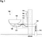
- Figure 1 illustrates a schematic of a toilet system [100], comprising a water closet [102], a flushing arrangement [104], and a flexible trapway arrangement [106].
- the water closet [102] is a typical toilet bowl adapted to receive faecal matter [108], as a user perform defaecation thereon.
- the water closet [102] is described to be a wall mounted closet, it may be obvious to a person skilled in the art that the water closet [102] may be a floor mounted closet as well.
- the water closet [102] is in fluid communication with a drain line [110] via the flexible trapway arrangement [106], for enabling evacuation of faecal matter [108] therefrom when flushed by the flush arrangement [104].
- the water closet [102] maintains a sump water [112] therein with use of the flexible trapway arrangement [106], which prevents sticking of faecal matter [108] in the water closet [102] as well as prevent the leakage of foul gases from the drain line [110] into the toilet area.
- a structure and arrangement of the flush arrangement [104] and the trapway arrangement [106] will be described in details in the forthcoming disclosure.
- the flush arrangement [104] is provided to flush faecal matter [108] from the water closet [102], when required.
- the flush arrangement [104] includes a flush tank [114] and a flush valve.
- the flush tank [114] is mounted on a water closet frame [116].
- the flush tank [114] stores flushing water required for performing flushing action.
- the flush tank [114] is a sealed pressurised tank fluidly connected to each of the water closet [102] and at least a component of the flexible trapway arrangement [106]. Therefore, flushing of water from the flush tank [114] results in sucking of air from at least one component of the flexible trapway arrangement [106].
- the flush valve is further incorporated within the flush tank [114], and is adapted to allow/ restrict a supply of water from the flush tank [114] to the water closet [102]. Particularly, as a user presses a flush button, the flush valve allows the flow of water from the flush tank [114] to the water closet [102] and perform the flushing action. Additionally, as the flush button is released, the flush valve restricts the flow of water from the flush tank [114] to the water closet [102].
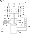
- FIG. 2 illustrates the schematic of the flexible trapway arrangement [106].
- the flexible trapway arrangement [106] includes a trapway [118] and a trap mechanism [120].
- the trapway [118] is a flexible hose pipe made up of resilient material, which fluidly connects the water closet [102] to the drain line [110].
- the trapway [118] is provided between a waste exit of the water closet [102] and a PVC elbow [122] of the drain line [110].
- a gasket inlet [124] is provided at an interface between the waste exit of the water closet [102] and the trapway [118].
- a gasket outlet [126] is provided at an interface between the PVC elbow [122] of the drain line [110] and the trapway [118].
- the gasket inlet [124] and the gasket outlet [126] prevent water leakage through the interfaces of the trapway [118]. With such arrangement of the trapway [118], a fluid connection of the water closet [102] to the drain line [110] is facilitated
- the trap mechanism [120] is provided to operate the trapway [118] in one of a constricted state and a dilated state.
- the trap mechanism [120] constricts at least a portion of the trapway [118] to restrict a flow of components therethrough.
- the trap mechanism [120] dilates the trapway [118] to allow a flow of components therethrough.
- the trap mechanism [120] automatically operates the trapway [118] in the constricted state, during normal operating conditions, namely, before/ after flushing conditions.
- the trap mechanism [120] automatically operates the trapway [118] in the dilated state, during flushing operating conditions.
- the mechanism operates the trapway [118] to operate in the dilated state, upon user intervention in emergency operating conditions.
- the trap mechanism [120] includes a first support plate [128] (a top support plate), a second support plate [130] (bottom support plate), and an actuation mechanism [132].
- the first support plate [128] is fixedly positioned to engage with a top periphery of the trapway [118].
- the second support plate [130] is movable relative to the first support plate [128], and engages with a bottom periphery of the trapway [118].
- the actuation mechanism [132] is provided to move the second support plate [130] relative to the first support plate [128]. Particularly, the actuation mechanism [132] moves the second support plate [130] towards/ proximal to the first support plate [128], in the constricted state of operation of the trapway [118].
- the actuation mechanism [132] moves the second support plate [130] away/ distal from the first support plate [128], in the dilated state of operation of the trapway [118].
- the actuation mechanism [132] includes a spring arrangement, and a double-acting piston and cylinder arrangement.
- the spring arrangement is provided between the first support plate [128] and the second support plate [130].
- the spring arrangement includes a couple of support studs [134], a couple of locknuts [136], and a couple of spring members [138], installed between the first support plate [128] and the second support plate [130].
- the support studs [134] and the locknuts [136] maintains a default length of the spring members [138], to maintain a default distance between the first support plate [128] and the second support plate [130].
- the spring members [138] maintain the second support plate [130] towards/ proximal the first support plate [128], to maintain trapway [118] in the constricted state. Thereby, by default, the spring members [138] of the trap mechanism [120], maintains the trapway [118] in the constricted state.
- the double-acting piston and cylinder arrangement is provided to move the second support plate [130] away/ distant from the first support plate [128], to automatically shift the trapway [118] from the constricted state to the dilated state, when required.
- the double-acting piston and cylinder includes a cylinder [140], and a piston [142] sliding within the cylinder [140].
- the piston [142] is connected to the second support plate [130], via a connecting rod. With such arrangement, the piston [142] defines a top chamber [144] and a bottom chamber [146] within the cylinder [140].
- the bottom chamber [146] is in fluid communication with the flush tank [114] of the flushing arrangement [104], via a pneumatic hose [148].
- the fluid connection facilitates sucking of air from the bottom chamber [146] of the cylinder [140], as the flushing operation is performed by the flush tank [114] of the flushing arrangement [104].
- sucking of air enables movement of the second support plate [130] away/ distal from the first support plate [128], and thus operating the trapway [118] in the dilated state in flushing operating conditions.
- the fluid connection facilitates supply of air to the bottom chamber [146] of the cylinder, as the flushing operation is released by the flush tank [114] of the flushing arrangement [104].
- Such supply of air enables movement of the second support plate [130] towards/ proximal to the first support plate [128], and thus operating the trapway [118] in the constricted state in the normal operating conditions, namely before/ after flushing operating conditions.
- An air spring [150] is also provided in fluid communication to the bottom chamber [146], to temporarily store air within itself during sudden flushing operations/ emergency operating conditions.
- a top chamber [144] of the cylinder [140] is fluidly connected to to an air bellow [152], via a check valve [154]. Further, a foot pedal [156] is connected to the air bellow [152].
- an application of pressure on the foot pedal [156] corresponds to a supply of air from the air chamber to the top chamber [144] of the cylinder [140] via the check valve [154].
- Such supply of air to the top chamber [144] of the cylinder [140] enables movement of the second support plate [130] away/ distal from the first support plate [128], and thus operating the trapway [118] in the dilated state in emergency operating conditions, upon manual intervention.
- a release of pressure from the foot pedal [156] corresponds to release of air from the top chamber [144] of the cylinder [140] to the air bellow [152] via the check valve [154].
- the trap mechanism [120] of the trapway [118] arrangement initially operates the trapway [118] in the constricted state. Furthermore, the trap mechanism [120] of the trapway [118] arrangement is provided to operate the trapway [118] differently in different operating conditions, namely (i) before flushing conditions, (ii) during flushing conditions, (iii) after flushing conditions, and (iv) emergency flushing conditions.
- the flush tank [114] of the flush arrangement is filled with water.
- air is filled in the bottom chamber [146] of the cylinder.
- the actuation mechanism [132] of the trap mechanism [120] is inoperative. Therefore, the spring member, with help of spring force, maintains the second support plate [130] towards/ proximal to the first support plate [128], to operate the trapway [118] in the constricted state.
- the trapway [118] is constricted, and thus the sump water [112] is prevented from exiting to the drain line [110].
- the sump water [112] is maintained within the water closet [102].
- the faecal matter [108] is always dropped inside the sump water [112] and doesn't stick on to the water closet [102].
- the flush button of the flushing arrangement [104] is pressed, for initiating flushing operation.
- water from the flush tank [114] starts flowing into the water closet [102].
- the flush tank [114] is the pressurized tank which forces/pressurizes water to flow from the flush tank [114] to the water closet [102]. Accordingly, as the water in the flush tank [114] starts reducing, the flush tank [114] sucks air from the bottom chamber [146] of the cylinder [140] of the actuation mechanism [132]. As the air is sucked from the bottom chamber [146], the piston [142] moves down from a top dead centre position to a bottom dead centre position within the cylinder [140].
- the actuation mechanism [132] moves the second support plate [130] away/ distant from the first support plate [128], thereby shifting the trapway [118] from the constricted state to the dilate state.
- the trapway [118] allows the components (sump water and faecal matter) in the water closet [102] to flow to the drain line [110], by way of water pressure of the flushing water.
- flushing operation is enabled. After performing the flushing operation, an after flushing operation takes place.
- the flush tank [114] of the flushing arrangement is refilled with flushing water.
- the air inside the flush tank [114] moves into the bottom chamber [146] of the cylinder [140].
- This action further pushes the piston [142] towards the top dead centre position within the cylinder [140].
- the second support plate [130] is moved towards/ proximal to the first support plate [128].
- the trap mechanism allows the trapway [118] to shift from the dilated state to the constricted state.
- the water closet [102] is allowed to be refilled with the sump water [112].
- the trapway [118] arrangement may require to be manually overridden. Particularly, during emergency operating conditions, the trapway [118] may require to be operated in the dilated state, without initiating an action by the flushing arrangement [104].
- the foot pedal [156] may be pressed to operate the trapway [118] in the dilated state, in the emergency operating conditions.
- the foot pedal [156] may be pressed to operate the trapway [118] in the dilated state in case of cleaning requirements of the water closet [102].
- the check valve [154] opens and air inside the air bellow [152] flows inside the top chamber [144] of the cylinder [140].
- Such supply of air to the top chamber [144] of the cylinder [140] enables movement of the second support plate [130] away/ distal from the first support plate [128], and thus operating the trapway [118] in the dilated state in emergency operating conditions, upon manual intervention.
- air on the bottom chamber [146] of the cylinder [140] is temporarily pushed into the air spring [150], and thus expanding the air spring [150].
- the foot pedal [156] is released from pressure. With release of pressure from the foot pedal [156], the air in top chamber [144] of the cylinder [140] is released back to the air bellow [152].
- the piston [142] moves upwards, thereby moving the second support plate [130] towards/ proximal to the first support plate [128]. This causes the trapway [118] to move from the dilated state to the constricted state.
- a pressure difference is created within the bottom chamber [146] of the cylinder [140], thus drawing air from the air spring [156] back to the bottom chamber [146] of the cylinder [140].
- the present invention takes into account a number of advantages.
- One such advantage is minimal water requirements.
- the disclosed flexible trapway arrangement [106] discloses usage of a flat flexible trapway for connecting the water closet [102] to the drain line [110]. Specifically, a need of complex inverted U channel is avoided.
- usage of the flat trapway requires minimal water requirement for flushing of faecal matter [108] from the water closet [102].
- the overall water consumption by the water closet [102] of the toilet system [100] is reduced optimally. This results in an increase in the functional efficiency of the water closet [102] of the toilet system [100]. This provides for the toilet arrangement with more eco-friendly nature, more functional efficiency, and less bulky.
- the disclosed flexible trapway arrangement [106] discloses usage of a flat flexible trapway for connecting the water closet [102] to the drain line [110]. Specifically, a need of complex inverted U channel is avoided. Thus, usage of the flat trapway [118] requires low water head, and thus the flush tank [114] can be placed at relatively reduced heights. Thus, reducing the vertical space requirement of the toilet system [100].
- the disclosed flexible trapway arrangement [106] discloses usage of a flat flexible trapway for connecting the water closet [102] to the drain line [110].
- the structure and arrangement of the water closet [102] is less complex. Therefore, manufacturing of the water closet [102] of the toilet system [100], such as but not limited to ceramic manufacturing process, is relatively easy and less cumbersome. Particularly, manufacturing process of such water closet [102], requires employment of less complex moulds and is thus relatively easy.
Landscapes
- Engineering & Computer Science (AREA)
- Mechanical Engineering (AREA)
- Aviation & Aerospace Engineering (AREA)
- Health & Medical Sciences (AREA)
- Life Sciences & Earth Sciences (AREA)
- Hydrology & Water Resources (AREA)
- Public Health (AREA)
- Water Supply & Treatment (AREA)
- Sanitary Device For Flush Toilet (AREA)
Description
- The present disclosure relates to a flexible trapway arrangement for a toilet system according to the preamble of claim 1.
- Toilet systems are known in sanitation industry, to enable persons to defecate in good sanitary conditions. A typical toilet system includes a water closet and a flush arrangement. The water closet is provided to receive faecal matter, when a user performs defecation thereon. The flush arrangement is provided to supply water to the water closet, for removing faecal matter therefrom by pushing the faecal matter to a drain line with use of water pressure.
- Water consumption optimization by a toilet system is also an essential requirement in addition to flushing. Typically, the toilet system requires not only more water, but also higher water head, to flush the faecal matter. The faecal matter is flushed to a drain line. The higher water head, here, relates to the potential energy of the water in the water storage tank of the flush arrangement. For such high water-head requirements, the water storage tank of the flush arrangement is required to be positioned at greater heights relative to the water closet. Such undesirable water consumption and higher water head requirements makes the toilet system less eco-friendly, functionally inefficient, and bulkier.
-
WO 2018/151361 A1 discloses a hydrolic waste water discharge device having a flexible waste water pipe which can be brought into a constricted state and into a dilated state. Two movable members above and below the pipe are arranged to exert force on the pipe for bringing same from the dilated state into the constricted State. This document discloses the features mentioned in the preamble of claim 1 and is considered to represent the closest prior art. -
DE 20 2014 005775 U1 discloses an electropneumatic toilet having a waste water valve which is operated by pressurized air. If the waste water power valve provides pressurized air to the waste water valve, the waste water valve opens, else closes. Further, the following prior art is cited in order to facilitate understanding the present invention:
US 3 314 084 A ,FR 2 916 773 A1 US 3 239 849 A ,US 2 308 478 A . - The water closet of the toilet system includes an integrally formed trapway, which connects the water closet to a drain line. The trapway allows for exit of water and faecal matter from the water closet to the drain line. Conventionally, the trapway is an inverted U-shaped channel including at least one vertical channel, to maintain a water seal of sump water in the water closet. While flushing, the faecal matter has to climb the vertical channel. This requires more flushing volume (more water) for flushing operations, which may be less eco-friendly. Additionally, such requirement of climbing the vertical channel requires a higher water head, which require the flush tank to be positioned at relatively higher heights. This may result in poor space-utilization. Such undesirable water consumption and higher water head requirements makes the toilet system less eco-friendly, functionally inefficient, and bulkier. Moreover, such Water closets with integrated complex structure of trapways is difficult to manufacture and require complex and expensive moulds for such manufacturing in an industrial set-up.
- Accordingly, in light of the aforementioned drawbacks and several other inherent in the existing arts, there is a well felt need to provide a water closet arrangement for the toilet system, which provides for, less wastage of water, increased overall functional efficiency, and minimal space requirements, and relatively easy manufacturing.
- The present invention is defined by the enclosed independent claim. The dependent claims define advantageous embodiments. Accordingly, the present invention relates to a flexible trapway arrangement for connecting a toilet system to a drain line. The trapway arrangement includes a trapway and a trap mechanism. The trapway is made up of resilient material. The trap mechanism is arranged with the trapway, and is adapted to operate the trapway in a constricted state and a dilated state. In the constricted state, the trap mechanism constricts at least a portion of the trapway to restrict a flow of components therethrough. In the dilated state, the trap mechanism dilates the trapway to allow a flow of components therethrough.
- One object of the present invention relates to a flexible trapway arrangement for a toilet system, which provides an overall reduction in water consumption, thereby making the toilet system functionally more efficient, and providing space optimization provision of the water closet of the toilet system.
- Yet another object of the present invention relates to a flexible trapway arrangement for a toilet system, which provides an overall reduction in water volume and water head needed for flushing process of the toilet system.
- Yet another object of the present invention relates to a flexible trapway arrangement for a toilet system, which provides for an easy manufacturing process of the water closet of the toilet system.
- The present invention, both as to its organization and manner of operation, together with further objects and advantages, may best be understood by reference to the following description, taken in connection with the accompanying drawings. These and other details of the present invention will be described in connection with the accompanying drawings, which are furnished only by way of illustration and not in limitation of the invention, and in which drawings:
-
Figure 1 illustrates a schematic view of a toilet system, with a trapway arrangement in accordance with the concepts of the present disclosure. -
Figure 2 illustrates a schematic view of a flexible trapway and a trap mechanism, in accordance with the concepts of the present disclosure. - In the following description, for the purposes of explanation, various specific details are set forth in order to provide a thorough understanding of embodiments of the present invention. It will be apparent, however, that embodiments of the present invention may be practiced without these specific details. Several features described hereafter can each be used independently of one another or with any combination of other features. An individual feature may not address any of the problems discussed above or might address only one of the problems discussed above. Some of the problems discussed above might not be fully addressed by any of the features described herein. Example embodiments of the present invention are described below, as illustrated in various drawings in which like reference numerals refer to the same parts throughout the different drawings.
-
Figure 1 illustrates a schematic of a toilet system [100], comprising a water closet [102], a flushing arrangement [104], and a flexible trapway arrangement [106]. - The water closet [102] is a typical toilet bowl adapted to receive faecal matter [108], as a user perform defaecation thereon. Although, the water closet [102] is described to be a wall mounted closet, it may be obvious to a person skilled in the art that the water closet [102] may be a floor mounted closet as well. The water closet [102] is in fluid communication with a drain line [110] via the flexible trapway arrangement [106], for enabling evacuation of faecal matter [108] therefrom when flushed by the flush arrangement [104]. Also, the water closet [102] maintains a sump water [112] therein with use of the flexible trapway arrangement [106], which prevents sticking of faecal matter [108] in the water closet [102] as well as prevent the leakage of foul gases from the drain line [110] into the toilet area. A structure and arrangement of the flush arrangement [104] and the trapway arrangement [106] will be described in details in the forthcoming disclosure.
- The flush arrangement [104] is provided to flush faecal matter [108] from the water closet [102], when required. The flush arrangement [104] includes a flush tank [114] and a flush valve. The flush tank [114] is mounted on a water closet frame [116]. The flush tank [114] stores flushing water required for performing flushing action. Notably, the flush tank [114] is a sealed pressurised tank fluidly connected to each of the water closet [102] and at least a component of the flexible trapway arrangement [106]. Therefore, flushing of water from the flush tank [114] results in sucking of air from at least one component of the flexible trapway arrangement [106]. The flush valve is further incorporated within the flush tank [114], and is adapted to allow/ restrict a supply of water from the flush tank [114] to the water closet [102]. Particularly, as a user presses a flush button, the flush valve allows the flow of water from the flush tank [114] to the water closet [102] and perform the flushing action. Additionally, as the flush button is released, the flush valve restricts the flow of water from the flush tank [114] to the water closet [102].
-
Figure 2 illustrates the schematic of the flexible trapway arrangement [106]. The flexible trapway arrangement [106] includes a trapway [118] and a trap mechanism [120]. The trapway [118] is a flexible hose pipe made up of resilient material, which fluidly connects the water closet [102] to the drain line [110]. Particularly, the trapway [118] is provided between a waste exit of the water closet [102] and a PVC elbow [122] of the drain line [110]. Notably, a gasket inlet [124] is provided at an interface between the waste exit of the water closet [102] and the trapway [118]. Additionally, a gasket outlet [126] is provided at an interface between the PVC elbow [122] of the drain line [110] and the trapway [118]. The gasket inlet [124] and the gasket outlet [126] prevent water leakage through the interfaces of the trapway [118]. With such arrangement of the trapway [118], a fluid connection of the water closet [102] to the drain line [110] is facilitated. - The trap mechanism [120] is provided to operate the trapway [118] in one of a constricted state and a dilated state. In the constricted state, the trap mechanism [120] constricts at least a portion of the trapway [118] to restrict a flow of components therethrough. In the dilated state, the trap mechanism [120] dilates the trapway [118] to allow a flow of components therethrough. Particularly, the trap mechanism [120] automatically operates the trapway [118] in the constricted state, during normal operating conditions, namely, before/ after flushing conditions. Moreover, the trap mechanism [120] automatically operates the trapway [118] in the dilated state, during flushing operating conditions. Also, the mechanism operates the trapway [118] to operate in the dilated state, upon user intervention in emergency operating conditions. A structure and arrangement of the trap mechanism [120] will now be described in detail.
- The trap mechanism [120] includes a first support plate [128] (a top support plate), a second support plate [130] (bottom support plate), and an actuation mechanism [132]. The first support plate [128] is fixedly positioned to engage with a top periphery of the trapway [118]. The second support plate [130] is movable relative to the first support plate [128], and engages with a bottom periphery of the trapway [118]. The actuation mechanism [132] is provided to move the second support plate [130] relative to the first support plate [128]. Particularly, the actuation mechanism [132] moves the second support plate [130] towards/ proximal to the first support plate [128], in the constricted state of operation of the trapway [118]. Also, the actuation mechanism [132] moves the second support plate [130] away/ distal from the first support plate [128], in the dilated state of operation of the trapway [118]. The actuation mechanism [132] includes a spring arrangement, and a double-acting piston and cylinder arrangement.
- The spring arrangement is provided between the first support plate [128] and the second support plate [130]. The spring arrangement includes a couple of support studs [134], a couple of locknuts [136], and a couple of spring members [138], installed between the first support plate [128] and the second support plate [130]. The support studs [134] and the locknuts [136] maintains a default length of the spring members [138], to maintain a default distance between the first support plate [128] and the second support plate [130]. The spring members [138] maintain the second support plate [130] towards/ proximal the first support plate [128], to maintain trapway [118] in the constricted state. Thereby, by default, the spring members [138] of the trap mechanism [120], maintains the trapway [118] in the constricted state.
- The double-acting piston and cylinder arrangement is provided to move the second support plate [130] away/ distant from the first support plate [128], to automatically shift the trapway [118] from the constricted state to the dilated state, when required. The double-acting piston and cylinder includes a cylinder [140], and a piston [142] sliding within the cylinder [140]. The piston [142] is connected to the second support plate [130], via a connecting rod. With such arrangement, the piston [142] defines a top chamber [144] and a bottom chamber [146] within the cylinder [140]. The bottom chamber [146] is in fluid communication with the flush tank [114] of the flushing arrangement [104], via a pneumatic hose [148]. The fluid connection facilitates sucking of air from the bottom chamber [146] of the cylinder [140], as the flushing operation is performed by the flush tank [114] of the flushing arrangement [104]. Such sucking of air enables movement of the second support plate [130] away/ distal from the first support plate [128], and thus operating the trapway [118] in the dilated state in flushing operating conditions. Also, the fluid connection facilitates supply of air to the bottom chamber [146] of the cylinder, as the flushing operation is released by the flush tank [114] of the flushing arrangement [104]. Such supply of air enables movement of the second support plate [130] towards/ proximal to the first support plate [128], and thus operating the trapway [118] in the constricted state in the normal operating conditions, namely before/ after flushing operating conditions. An air spring [150] is also provided in fluid communication to the bottom chamber [146], to temporarily store air within itself during sudden flushing operations/ emergency operating conditions. Furthermore, a top chamber [144] of the cylinder [140] is fluidly connected to to an air bellow [152], via a check valve [154]. Further, a foot pedal [156] is connected to the air bellow [152]. With such arrangement, an application of pressure on the foot pedal [156] corresponds to a supply of air from the air chamber to the top chamber [144] of the cylinder [140] via the check valve [154]. Such supply of air to the top chamber [144] of the cylinder [140] enables movement of the second support plate [130] away/ distal from the first support plate [128], and thus operating the trapway [118] in the dilated state in emergency operating conditions, upon manual intervention. Also, a release of pressure from the foot pedal [156] corresponds to release of air from the top chamber [144] of the cylinder [140] to the air bellow [152] via the check valve [154].
- In operation, the trap mechanism [120] of the trapway [118] arrangement initially operates the trapway [118] in the constricted state. Furthermore, the trap mechanism [120] of the trapway [118] arrangement is provided to operate the trapway [118] differently in different operating conditions, namely (i) before flushing conditions, (ii) during flushing conditions, (iii) after flushing conditions, and (iv) emergency flushing conditions.
- During before flushing operating conditions, the flush tank [114] of the flush arrangement is filled with water. In such situations, air is filled in the bottom chamber [146] of the cylinder. Thus, the actuation mechanism [132] of the trap mechanism [120] is inoperative. Therefore, the spring member, with help of spring force, maintains the second support plate [130] towards/ proximal to the first support plate [128], to operate the trapway [118] in the constricted state. In the constricted state, the trapway [118] is constricted, and thus the sump water [112] is prevented from exiting to the drain line [110]. Thereby, the sump water [112] is maintained within the water closet [102]. Thereby, upon usage of the water closet [102], the faecal matter [108] is always dropped inside the sump water [112] and doesn't stick on to the water closet [102].
- During flushing operating conditions, the flush button of the flushing arrangement [104] is pressed, for initiating flushing operation. Upon performing such action, water from the flush tank [114] starts flowing into the water closet [102]. As is already mentioned, the flush tank [114] is the pressurized tank which forces/pressurizes water to flow from the flush tank [114] to the water closet [102]. Accordingly, as the water in the flush tank [114] starts reducing, the flush tank [114] sucks air from the bottom chamber [146] of the cylinder [140] of the actuation mechanism [132]. As the air is sucked from the bottom chamber [146], the piston [142] moves down from a top dead centre position to a bottom dead centre position within the cylinder [140]. With such action, the actuation mechanism [132] moves the second support plate [130] away/ distant from the first support plate [128], thereby shifting the trapway [118] from the constricted state to the dilate state. In the dilated state, the trapway [118] allows the components (sump water and faecal matter) in the water closet [102] to flow to the drain line [110], by way of water pressure of the flushing water. Thus, flushing operation is enabled. After performing the flushing operation, an after flushing operation takes place.
- During after flushing operating conditions, the flush tank [114] of the flushing arrangement is refilled with flushing water. During filling, the air inside the flush tank [114] moves into the bottom chamber [146] of the cylinder [140]. This action further pushes the piston [142] towards the top dead centre position within the cylinder [140]. With such action, the second support plate [130] is moved towards/ proximal to the first support plate [128]. Thereby, the trap mechanism allows the trapway [118] to shift from the dilated state to the constricted state. Thus, the water closet [102] is allowed to be refilled with the sump water [112].
- During emergency operation conditions, the trapway [118] arrangement may require to be manually overridden. Particularly, during emergency operating conditions, the trapway [118] may require to be operated in the dilated state, without initiating an action by the flushing arrangement [104]. For this purpose, the foot pedal [156] may be pressed to operate the trapway [118] in the dilated state, in the emergency operating conditions. For example, the foot pedal [156] may be pressed to operate the trapway [118] in the dilated state in case of cleaning requirements of the water closet [102]. Upon pressing the foot pedal [156], the check valve [154] opens and air inside the air bellow [152] flows inside the top chamber [144] of the cylinder [140]. Such supply of air to the top chamber [144] of the cylinder [140] enables movement of the second support plate [130] away/ distal from the first support plate [128], and thus operating the trapway [118] in the dilated state in emergency operating conditions, upon manual intervention. In such conditions, air on the bottom chamber [146] of the cylinder [140] is temporarily pushed into the air spring [150], and thus expanding the air spring [150]. Upon completion of the emergency operating conditions, the foot pedal [156] is released from pressure. With release of pressure from the foot pedal [156], the air in top chamber [144] of the cylinder [140] is released back to the air bellow [152]. Thus, the piston [142] moves upwards, thereby moving the second support plate [130] towards/ proximal to the first support plate [128]. This causes the trapway [118] to move from the dilated state to the constricted state. During the return stroke of the piston [142], a pressure difference is created within the bottom chamber [146] of the cylinder [140], thus drawing air from the air spring [156] back to the bottom chamber [146] of the cylinder [140].
- The present invention takes into account a number of advantages. One such advantage is minimal water requirements. Particularly, the disclosed flexible trapway arrangement [106] discloses usage of a flat flexible trapway for connecting the water closet [102] to the drain line [110]. Specifically, a need of complex inverted U channel is avoided. Thus, usage of the flat trapway requires minimal water requirement for flushing of faecal matter [108] from the water closet [102]. Thereby, the overall water consumption by the water closet [102] of the toilet system [100] is reduced optimally. This results in an increase in the functional efficiency of the water closet [102] of the toilet system [100]. This provides for the toilet arrangement with more eco-friendly nature, more functional efficiency, and less bulky.
- Another advantage of the disclosed trapway [118] arrangement relates to space optimization. The disclosed flexible trapway arrangement [106] discloses usage of a flat flexible trapway for connecting the water closet [102] to the drain line [110]. Specifically, a need of complex inverted U channel is avoided. Thus, usage of the flat trapway [118] requires low water head, and thus the flush tank [114] can be placed at relatively reduced heights. Thus, reducing the vertical space requirement of the toilet system [100].
- Yet another advantage of the present invention relates to improved manufacturing processes for manufacture of the water closet [102]. The disclosed flexible trapway arrangement [106] discloses usage of a flat flexible trapway for connecting the water closet [102] to the drain line [110]. As the water closet [110] of the disclosed toilet arrangement avoids a need of integrally formed trapway [118], the structure and arrangement of the water closet [102] is less complex. Therefore, manufacturing of the water closet [102] of the toilet system [100], such as but not limited to ceramic manufacturing process, is relatively easy and less cumbersome. Particularly, manufacturing process of such water closet [102], requires employment of less complex moulds and is thus relatively easy.
-
- 100-
- Toilet System
- 102-
- Water closet
- 104-
- Flushing arrangement
- 106-
- Flexible Trapway arrangement
- 108-
- Faecal matter
- 110-
- Drain line
- 112-
- Sump water
- 114-
- Flush tank
- 116-
- Water closet frame
- 118-
- Trapway
- 120-
- Trap mechanism
- 122-
- PVC elbow
- 124-
- Gasket inlet
- 126-
- Gasket oulet
- 128-
- First support plate
- 130-
- Second support plate
- 132-
- Actuation mechanism
- 134-
- Couple of support studs
- 136-
- Couple of locknuts
- 138-
- Couple of spring members
- 140-
- Cylinder
- 142-
- Piston
- 144-
- Top chamber
- 146-
- Bottom chamber
- 148-
- Pneumatic hose
- 150-
- Air spring
- 152-
- Air bellow
- 154-
- Check valve
- 156-
- Foot pedal
Claims (10)
- A flexible trapway arrangement [106] for connecting a toilet system [100] to a drain line [110], the trapway arrangement comprising:- a trapway [118] made up of resilient material; and- a trap mechanism [120] arranged with the trapway [118], the trap mechanism [120] being adapted to operate the trapway [118] in a constricted state and a dilated state, whereinin the constricted state, the trap mechanism [120] constricts at least a portion of the trapway [118] to restrict a flow of components therethrough, andin the dilated state, the trap mechanism [120] dilates the trapway [118] to allow a flow of components therethrough, wherein the trap mechanism [120] includes:a first support plate [128] positioned to engage with one side of the trapway [118], the first support plate [128] being positioned in the trap mechanism [120];a second support plate [130] positioned to engage with an opposite side of the trapway [118], the second support plate [130] being movable relative to the first support plate [128]; andan actuation mechanism [132] adapted to:move the second support plate [130] against the first support plate [128], to adjust the trapway [118] to operate in the constricted state, andmove the second support plate [130] away from the first support plate [128] to adjust the trapway [118] to operate inthe dilated state, characterised in that the first support plate [128] is fixedly positioned in the trap mechanism [120].
- The flexible trapway arrangement [106] as claimed in claim 1, wherein the trapway [118] is a hose pipe for fluidly connecting the toilet system [100] to the drain line [110].
- The flexible trapway arrangement [106] as claimed in claim 1, is operated in the constricted state during normal operating conditions of the toilet system [100].
- The flexible trapway arrangement [106] as claimed in claim 1, is operated in the dilated state during flushing operating conditions of the toilet system [100].
- The flexible trapway arrangement [106] as claimed in claim 1, wherein the actuation mechanism [132] is double-acting piston and cylinder arrangement adapted to move the second support plate [130] against the first support plate [128] for operating the trapway [118] in the constricted state, and move the second support plate [130] away from the first support plate [128] for operating the trapway [118] in the dilated state.
- The flexible trapway arrangement [106] as claimed in claim 1, wherein the actuation mechanism [132] includes a spring arrangement positioned between the first support plate [128] and the second support plate [130], for maintaining the second support plate [130] towards/proximal to the first support plate [128] and operating the trapway [118] in the constricted state, during normal operating conditions of the toilet system [100].
- The flexible trapway arrangement [106] as claimed in claim 5, wherein the double-acting piston and cylinder arrangement is pneumatically connected to a flush tank [114] of the toilet system [100], such that the double-acting piston and cylinder arrangement moves the second support plate [130] towards the first support plate [128] for operating the trapway [118] in the constricted state during normal operating conditions of the toilet system [100].
- The flexible trapway arrangement [106] as claimed in claim 7, wherein the flush tank [114] is a fluid-tight tank adapted to suck air from the double- acting piston and cylinder arrangement during flushing operating condition, and supply back air to the double-acting piston and cylinder arrangement during normal operating conditions.
- The flexible trapway arrangement [106] as claimed in claim 5, wherein the double-acting piston and cylinder arrangement is pneumatically connected to a pedal operated bellow.
- The flexible trapway arrangement [106] as claimed in claim 9, wherein the pedal operated bellow is arranged to manipulate the double-acting piston and cylinder arrangement to move the second support plate [130] away from the first support plate [128], during manual intervention1 operating conditions of the toilet system [100].
Applications Claiming Priority (1)
| Application Number | Priority Date | Filing Date | Title |
|---|---|---|---|
| IN201911023306 | 2019-06-12 |
Publications (2)
| Publication Number | Publication Date |
|---|---|
| EP3751063A1 EP3751063A1 (en) | 2020-12-16 |
| EP3751063B1 true EP3751063B1 (en) | 2024-08-14 |
Family
ID=71083401
Family Applications (1)
| Application Number | Title | Priority Date | Filing Date |
|---|---|---|---|
| EP20179015.1A Active EP3751063B1 (en) | 2019-06-12 | 2020-06-09 | Flexible shape changing trapway arrangement for toilet system |
Country Status (1)
| Country | Link |
|---|---|
| EP (1) | EP3751063B1 (en) |
Families Citing this family (1)
| Publication number | Priority date | Publication date | Assignee | Title |
|---|---|---|---|---|
| CN115306001B (en) * | 2021-05-08 | 2025-05-02 | 深圳市恒致云科技有限公司 | Flushing mechanism, drainage device and bathroom equipment |
Family Cites Families (6)
| Publication number | Priority date | Publication date | Assignee | Title |
|---|---|---|---|---|
| US2308478A (en) * | 1941-11-06 | 1943-01-12 | Crane Co | Flush valve actuator |
| US3239849A (en) * | 1962-03-22 | 1966-03-15 | Liljendahl Sven Algot Joel | Method of hydro-pneumatic conveying, system and apparatus |
| US3314084A (en) * | 1964-09-23 | 1967-04-18 | Balikjian Nishan | Automatic flushing system |
| FR2916773B1 (en) * | 2007-05-31 | 2016-02-19 | Presto Robinets Sa | DEVICE FOR CONTROLLING A HUNTING TANK |
| DE202014005775U1 (en) * | 2014-07-17 | 2015-10-20 | Evac Gmbh | Electropneumatic pilot control unit |
| KR101843539B1 (en) * | 2017-02-20 | 2018-04-02 | 주식회사 호두 | Vacuum and hydraulic discharge equipment |
-
2020
- 2020-06-09 EP EP20179015.1A patent/EP3751063B1/en active Active
Also Published As
| Publication number | Publication date |
|---|---|
| EP3751063A1 (en) | 2020-12-16 |
Similar Documents
| Publication | Publication Date | Title |
|---|---|---|
| CN101730775B (en) | Pressurized trap water saving toilet | |
| EP0430521A2 (en) | Flushing mechanisms | |
| US4955921A (en) | Flushing mechanism using phase change fluid | |
| CN1890438B (en) | Device for operating an adjustable siphon of a toilet | |
| EP3751063A1 (en) | Flexible shape changing trapway arrangement for toilet system | |
| EP2196585A2 (en) | Toilet bowl with flush flow control | |
| US9695583B2 (en) | Flush toilet with build-in one-way valve system for use in unclogging clogs and for efficient water-saving flush operations and related methods | |
| US6061844A (en) | Water-conserving toilet having independently flushable main and urinal bowls | |
| US20160289937A1 (en) | Primed siphonic flush toilet | |
| US6279176B1 (en) | Low water toilet | |
| EP2177675A1 (en) | Dual-flush valve for cistern | |
| US12152380B2 (en) | Pneumatic valve control device | |
| EP2949825B1 (en) | Improved dual control mode-type deodorising and water drainage valve | |
| CN210529861U (en) | Water-air mixed flushing and supercharging device | |
| US11873630B2 (en) | Pneumatic valve control device | |
| CN203626017U (en) | Multi-control-type hydraulic closestool water tank water blowing flushing device | |
| CN111452919B (en) | Portable toilet for ship | |
| US20220282469A1 (en) | Toilet device and method for flushing a toilet bowl | |
| CN212715215U (en) | Intelligent vacuum toilet bowl | |
| CN210887479U (en) | Deodorant toilet lid of foam and closestool | |
| CN223706637U (en) | Anti-blocking self-adjusting intelligent closestool | |
| US9687126B2 (en) | Series-operation toilet system with hydraulic seat lifting and flushing | |
| US20220220717A1 (en) | Flush toilet | |
| CN201730173U (en) | Water-saving compressed air toilet bowl | |
| CN102936917A (en) | Automatic flushing toilet |
Legal Events
| Date | Code | Title | Description |
|---|---|---|---|
| PUAI | Public reference made under article 153(3) epc to a published international application that has entered the european phase |
Free format text: ORIGINAL CODE: 0009012 |
|
| STAA | Information on the status of an ep patent application or granted ep patent |
Free format text: STATUS: THE APPLICATION HAS BEEN PUBLISHED |
|
| AK | Designated contracting states |
Kind code of ref document: A1 Designated state(s): AL AT BE BG CH CY CZ DE DK EE ES FI FR GB GR HR HU IE IS IT LI LT LU LV MC MK MT NL NO PL PT RO RS SE SI SK SM TR |
|
| AX | Request for extension of the european patent |
Extension state: BA ME |
|
| STAA | Information on the status of an ep patent application or granted ep patent |
Free format text: STATUS: REQUEST FOR EXAMINATION WAS MADE |
|
| 17P | Request for examination filed |
Effective date: 20210511 |
|
| RBV | Designated contracting states (corrected) |
Designated state(s): AL AT BE BG CH CY CZ DE DK EE ES FI FR GB GR HR HU IE IS IT LI LT LU LV MC MK MT NL NO PL PT RO RS SE SI SK SM TR |
|
| STAA | Information on the status of an ep patent application or granted ep patent |
Free format text: STATUS: EXAMINATION IS IN PROGRESS |
|
| 17Q | First examination report despatched |
Effective date: 20221025 |
|
| GRAP | Despatch of communication of intention to grant a patent |
Free format text: ORIGINAL CODE: EPIDOSNIGR1 |
|
| STAA | Information on the status of an ep patent application or granted ep patent |
Free format text: STATUS: GRANT OF PATENT IS INTENDED |
|
| INTG | Intention to grant announced |
Effective date: 20240327 |
|
| GRAS | Grant fee paid |
Free format text: ORIGINAL CODE: EPIDOSNIGR3 |
|
| P01 | Opt-out of the competence of the unified patent court (upc) registered |
Free format text: CASE NUMBER: APP_33703/2024 Effective date: 20240605 |
|
| GRAA | (expected) grant |
Free format text: ORIGINAL CODE: 0009210 |
|
| STAA | Information on the status of an ep patent application or granted ep patent |
Free format text: STATUS: THE PATENT HAS BEEN GRANTED |
|
| AK | Designated contracting states |
Kind code of ref document: B1 Designated state(s): AL AT BE BG CH CY CZ DE DK EE ES FI FR GB GR HR HU IE IS IT LI LT LU LV MC MK MT NL NO PL PT RO RS SE SI SK SM TR |
|
| REG | Reference to a national code |
Ref country code: GB Ref legal event code: FG4D |
|
| RIN1 | Information on inventor provided before grant (corrected) |
Inventor name: NATESH, ABHINAY Inventor name: GUPTA, ANSHUMAN |
|
| REG | Reference to a national code |
Ref country code: CH Ref legal event code: EP |
|
| REG | Reference to a national code |
Ref country code: DE Ref legal event code: R096 Ref document number: 602020035631 Country of ref document: DE |
|
| REG | Reference to a national code |
Ref country code: IE Ref legal event code: FG4D |
|
| REG | Reference to a national code |
Ref country code: LT Ref legal event code: MG9D |
|
| REG | Reference to a national code |
Ref country code: NL Ref legal event code: MP Effective date: 20240814 |
|
| PG25 | Lapsed in a contracting state [announced via postgrant information from national office to epo] |
Ref country code: NO Free format text: LAPSE BECAUSE OF FAILURE TO SUBMIT A TRANSLATION OF THE DESCRIPTION OR TO PAY THE FEE WITHIN THE PRESCRIBED TIME-LIMIT Effective date: 20241114 |
|
| REG | Reference to a national code |
Ref country code: AT Ref legal event code: MK05 Ref document number: 1713416 Country of ref document: AT Kind code of ref document: T Effective date: 20240814 |
|
| PG25 | Lapsed in a contracting state [announced via postgrant information from national office to epo] |
Ref country code: FI Free format text: LAPSE BECAUSE OF FAILURE TO SUBMIT A TRANSLATION OF THE DESCRIPTION OR TO PAY THE FEE WITHIN THE PRESCRIBED TIME-LIMIT Effective date: 20240814 Ref country code: NL Free format text: LAPSE BECAUSE OF FAILURE TO SUBMIT A TRANSLATION OF THE DESCRIPTION OR TO PAY THE FEE WITHIN THE PRESCRIBED TIME-LIMIT Effective date: 20240814 Ref country code: PT Free format text: LAPSE BECAUSE OF FAILURE TO SUBMIT A TRANSLATION OF THE DESCRIPTION OR TO PAY THE FEE WITHIN THE PRESCRIBED TIME-LIMIT Effective date: 20241216 Ref country code: GR Free format text: LAPSE BECAUSE OF FAILURE TO SUBMIT A TRANSLATION OF THE DESCRIPTION OR TO PAY THE FEE WITHIN THE PRESCRIBED TIME-LIMIT Effective date: 20241115 Ref country code: PL Free format text: LAPSE BECAUSE OF FAILURE TO SUBMIT A TRANSLATION OF THE DESCRIPTION OR TO PAY THE FEE WITHIN THE PRESCRIBED TIME-LIMIT Effective date: 20240814 |
|
| PG25 | Lapsed in a contracting state [announced via postgrant information from national office to epo] |
Ref country code: BG Free format text: LAPSE BECAUSE OF FAILURE TO SUBMIT A TRANSLATION OF THE DESCRIPTION OR TO PAY THE FEE WITHIN THE PRESCRIBED TIME-LIMIT Effective date: 20240814 |
|
| PG25 | Lapsed in a contracting state [announced via postgrant information from national office to epo] |
Ref country code: LV Free format text: LAPSE BECAUSE OF FAILURE TO SUBMIT A TRANSLATION OF THE DESCRIPTION OR TO PAY THE FEE WITHIN THE PRESCRIBED TIME-LIMIT Effective date: 20240814 |
|
| PG25 | Lapsed in a contracting state [announced via postgrant information from national office to epo] |
Ref country code: AT Free format text: LAPSE BECAUSE OF FAILURE TO SUBMIT A TRANSLATION OF THE DESCRIPTION OR TO PAY THE FEE WITHIN THE PRESCRIBED TIME-LIMIT Effective date: 20240814 Ref country code: IS Free format text: LAPSE BECAUSE OF FAILURE TO SUBMIT A TRANSLATION OF THE DESCRIPTION OR TO PAY THE FEE WITHIN THE PRESCRIBED TIME-LIMIT Effective date: 20241214 |
|
| PG25 | Lapsed in a contracting state [announced via postgrant information from national office to epo] |
Ref country code: HR Free format text: LAPSE BECAUSE OF FAILURE TO SUBMIT A TRANSLATION OF THE DESCRIPTION OR TO PAY THE FEE WITHIN THE PRESCRIBED TIME-LIMIT Effective date: 20240814 |
|
| PG25 | Lapsed in a contracting state [announced via postgrant information from national office to epo] |
Ref country code: ES Free format text: LAPSE BECAUSE OF FAILURE TO SUBMIT A TRANSLATION OF THE DESCRIPTION OR TO PAY THE FEE WITHIN THE PRESCRIBED TIME-LIMIT Effective date: 20240814 Ref country code: RS Free format text: LAPSE BECAUSE OF FAILURE TO SUBMIT A TRANSLATION OF THE DESCRIPTION OR TO PAY THE FEE WITHIN THE PRESCRIBED TIME-LIMIT Effective date: 20241114 |
|
| PG25 | Lapsed in a contracting state [announced via postgrant information from national office to epo] |
Ref country code: RS Free format text: LAPSE BECAUSE OF FAILURE TO SUBMIT A TRANSLATION OF THE DESCRIPTION OR TO PAY THE FEE WITHIN THE PRESCRIBED TIME-LIMIT Effective date: 20241114 Ref country code: PT Free format text: LAPSE BECAUSE OF FAILURE TO SUBMIT A TRANSLATION OF THE DESCRIPTION OR TO PAY THE FEE WITHIN THE PRESCRIBED TIME-LIMIT Effective date: 20241216 Ref country code: PL Free format text: LAPSE BECAUSE OF FAILURE TO SUBMIT A TRANSLATION OF THE DESCRIPTION OR TO PAY THE FEE WITHIN THE PRESCRIBED TIME-LIMIT Effective date: 20240814 Ref country code: NO Free format text: LAPSE BECAUSE OF FAILURE TO SUBMIT A TRANSLATION OF THE DESCRIPTION OR TO PAY THE FEE WITHIN THE PRESCRIBED TIME-LIMIT Effective date: 20241114 Ref country code: NL Free format text: LAPSE BECAUSE OF FAILURE TO SUBMIT A TRANSLATION OF THE DESCRIPTION OR TO PAY THE FEE WITHIN THE PRESCRIBED TIME-LIMIT Effective date: 20240814 Ref country code: LV Free format text: LAPSE BECAUSE OF FAILURE TO SUBMIT A TRANSLATION OF THE DESCRIPTION OR TO PAY THE FEE WITHIN THE PRESCRIBED TIME-LIMIT Effective date: 20240814 Ref country code: IS Free format text: LAPSE BECAUSE OF FAILURE TO SUBMIT A TRANSLATION OF THE DESCRIPTION OR TO PAY THE FEE WITHIN THE PRESCRIBED TIME-LIMIT Effective date: 20241214 Ref country code: HR Free format text: LAPSE BECAUSE OF FAILURE TO SUBMIT A TRANSLATION OF THE DESCRIPTION OR TO PAY THE FEE WITHIN THE PRESCRIBED TIME-LIMIT Effective date: 20240814 Ref country code: GR Free format text: LAPSE BECAUSE OF FAILURE TO SUBMIT A TRANSLATION OF THE DESCRIPTION OR TO PAY THE FEE WITHIN THE PRESCRIBED TIME-LIMIT Effective date: 20241115 Ref country code: FI Free format text: LAPSE BECAUSE OF FAILURE TO SUBMIT A TRANSLATION OF THE DESCRIPTION OR TO PAY THE FEE WITHIN THE PRESCRIBED TIME-LIMIT Effective date: 20240814 Ref country code: ES Free format text: LAPSE BECAUSE OF FAILURE TO SUBMIT A TRANSLATION OF THE DESCRIPTION OR TO PAY THE FEE WITHIN THE PRESCRIBED TIME-LIMIT Effective date: 20240814 Ref country code: BG Free format text: LAPSE BECAUSE OF FAILURE TO SUBMIT A TRANSLATION OF THE DESCRIPTION OR TO PAY THE FEE WITHIN THE PRESCRIBED TIME-LIMIT Effective date: 20240814 Ref country code: AT Free format text: LAPSE BECAUSE OF FAILURE TO SUBMIT A TRANSLATION OF THE DESCRIPTION OR TO PAY THE FEE WITHIN THE PRESCRIBED TIME-LIMIT Effective date: 20240814 |
|
| PG25 | Lapsed in a contracting state [announced via postgrant information from national office to epo] |
Ref country code: DK Free format text: LAPSE BECAUSE OF FAILURE TO SUBMIT A TRANSLATION OF THE DESCRIPTION OR TO PAY THE FEE WITHIN THE PRESCRIBED TIME-LIMIT Effective date: 20240814 Ref country code: RO Free format text: LAPSE BECAUSE OF FAILURE TO SUBMIT A TRANSLATION OF THE DESCRIPTION OR TO PAY THE FEE WITHIN THE PRESCRIBED TIME-LIMIT Effective date: 20240814 Ref country code: SM Free format text: LAPSE BECAUSE OF FAILURE TO SUBMIT A TRANSLATION OF THE DESCRIPTION OR TO PAY THE FEE WITHIN THE PRESCRIBED TIME-LIMIT Effective date: 20240814 |
|
| PG25 | Lapsed in a contracting state [announced via postgrant information from national office to epo] |
Ref country code: EE Free format text: LAPSE BECAUSE OF FAILURE TO SUBMIT A TRANSLATION OF THE DESCRIPTION OR TO PAY THE FEE WITHIN THE PRESCRIBED TIME-LIMIT Effective date: 20240814 |
|
| PG25 | Lapsed in a contracting state [announced via postgrant information from national office to epo] |
Ref country code: CZ Free format text: LAPSE BECAUSE OF FAILURE TO SUBMIT A TRANSLATION OF THE DESCRIPTION OR TO PAY THE FEE WITHIN THE PRESCRIBED TIME-LIMIT Effective date: 20240814 |
|
| PG25 | Lapsed in a contracting state [announced via postgrant information from national office to epo] |
Ref country code: IT Free format text: LAPSE BECAUSE OF FAILURE TO SUBMIT A TRANSLATION OF THE DESCRIPTION OR TO PAY THE FEE WITHIN THE PRESCRIBED TIME-LIMIT Effective date: 20240814 Ref country code: SK Free format text: LAPSE BECAUSE OF FAILURE TO SUBMIT A TRANSLATION OF THE DESCRIPTION OR TO PAY THE FEE WITHIN THE PRESCRIBED TIME-LIMIT Effective date: 20240814 |
|
| REG | Reference to a national code |
Ref country code: DE Ref legal event code: R097 Ref document number: 602020035631 Country of ref document: DE |
|
| PLBE | No opposition filed within time limit |
Free format text: ORIGINAL CODE: 0009261 |
|
| STAA | Information on the status of an ep patent application or granted ep patent |
Free format text: STATUS: NO OPPOSITION FILED WITHIN TIME LIMIT |
|
| PGFP | Annual fee paid to national office [announced via postgrant information from national office to epo] |
Ref country code: DE Payment date: 20250626 Year of fee payment: 6 |
|
| PGFP | Annual fee paid to national office [announced via postgrant information from national office to epo] |
Ref country code: GB Payment date: 20250506 Year of fee payment: 6 |
|
| PGFP | Annual fee paid to national office [announced via postgrant information from national office to epo] |
Ref country code: FR Payment date: 20250624 Year of fee payment: 6 |
|
| 26N | No opposition filed |
Effective date: 20250515 |
|
| PG25 | Lapsed in a contracting state [announced via postgrant information from national office to epo] |
Ref country code: SE Free format text: LAPSE BECAUSE OF FAILURE TO SUBMIT A TRANSLATION OF THE DESCRIPTION OR TO PAY THE FEE WITHIN THE PRESCRIBED TIME-LIMIT Effective date: 20240814 |
|
| REG | Reference to a national code |
Ref country code: CH Ref legal event code: H13 Free format text: ST27 STATUS EVENT CODE: U-0-0-H10-H13 (AS PROVIDED BY THE NATIONAL OFFICE) Effective date: 20260127 |
|
| PG25 | Lapsed in a contracting state [announced via postgrant information from national office to epo] |
Ref country code: MC Free format text: LAPSE BECAUSE OF FAILURE TO SUBMIT A TRANSLATION OF THE DESCRIPTION OR TO PAY THE FEE WITHIN THE PRESCRIBED TIME-LIMIT Effective date: 20240814 |
|
| PG25 | Lapsed in a contracting state [announced via postgrant information from national office to epo] |
Ref country code: LU Free format text: LAPSE BECAUSE OF NON-PAYMENT OF DUE FEES Effective date: 20250609 |
|
| REG | Reference to a national code |
Ref country code: BE Ref legal event code: MM Effective date: 20250630 |
|
| PG25 | Lapsed in a contracting state [announced via postgrant information from national office to epo] |
Ref country code: IE Free format text: LAPSE BECAUSE OF NON-PAYMENT OF DUE FEES Effective date: 20250609 |
|
| PG25 | Lapsed in a contracting state [announced via postgrant information from national office to epo] |
Ref country code: BE Free format text: LAPSE BECAUSE OF NON-PAYMENT OF DUE FEES Effective date: 20250630 |
|
| PG25 | Lapsed in a contracting state [announced via postgrant information from national office to epo] |
Ref country code: CH Free format text: LAPSE BECAUSE OF NON-PAYMENT OF DUE FEES Effective date: 20250630 |