EP3750819B1 - A container - Google Patents
A container Download PDFInfo
- Publication number
- EP3750819B1 EP3750819B1 EP20178628.2A EP20178628A EP3750819B1 EP 3750819 B1 EP3750819 B1 EP 3750819B1 EP 20178628 A EP20178628 A EP 20178628A EP 3750819 B1 EP3750819 B1 EP 3750819B1
- Authority
- EP
- European Patent Office
- Prior art keywords
- mixing chamber
- container
- storage chamber
- closure element
- wall
- Prior art date
- Legal status (The legal status is an assumption and is not a legal conclusion. Google has not performed a legal analysis and makes no representation as to the accuracy of the status listed.)
- Revoked
Links
Images



Classifications
-
- B—PERFORMING OPERATIONS; TRANSPORTING
- B65—CONVEYING; PACKING; STORING; HANDLING THIN OR FILAMENTARY MATERIAL
- B65D—CONTAINERS FOR STORAGE OR TRANSPORT OF ARTICLES OR MATERIALS, e.g. BAGS, BARRELS, BOTTLES, BOXES, CANS, CARTONS, CRATES, DRUMS, JARS, TANKS, HOPPERS, FORWARDING CONTAINERS; ACCESSORIES, CLOSURES, OR FITTINGS THEREFOR; PACKAGING ELEMENTS; PACKAGES
- B65D81/00—Containers, packaging elements, or packages, for contents presenting particular transport or storage problems, or adapted to be used for non-packaging purposes after removal of contents
- B65D81/32—Containers, packaging elements, or packages, for contents presenting particular transport or storage problems, or adapted to be used for non-packaging purposes after removal of contents for packaging two or more different materials which must be maintained separate prior to use in admixture
- B65D81/3261—Flexible containers having several compartments
-
- B—PERFORMING OPERATIONS; TRANSPORTING
- B65—CONVEYING; PACKING; STORING; HANDLING THIN OR FILAMENTARY MATERIAL
- B65D—CONTAINERS FOR STORAGE OR TRANSPORT OF ARTICLES OR MATERIALS, e.g. BAGS, BARRELS, BOTTLES, BOXES, CANS, CARTONS, CRATES, DRUMS, JARS, TANKS, HOPPERS, FORWARDING CONTAINERS; ACCESSORIES, CLOSURES, OR FITTINGS THEREFOR; PACKAGING ELEMENTS; PACKAGES
- B65D1/00—Rigid or semi-rigid containers having bodies formed in one piece, e.g. by casting metallic material, by moulding plastics, by blowing vitreous material, by throwing ceramic material, by moulding pulped fibrous material or by deep-drawing operations performed on sheet material
- B65D1/02—Bottles or similar containers with necks or like restricted apertures, designed for pouring contents
- B65D1/0223—Bottles or similar containers with necks or like restricted apertures, designed for pouring contents characterised by shape
- B65D1/0292—Foldable bottles
-
- B—PERFORMING OPERATIONS; TRANSPORTING
- B65—CONVEYING; PACKING; STORING; HANDLING THIN OR FILAMENTARY MATERIAL
- B65D—CONTAINERS FOR STORAGE OR TRANSPORT OF ARTICLES OR MATERIALS, e.g. BAGS, BARRELS, BOTTLES, BOXES, CANS, CARTONS, CRATES, DRUMS, JARS, TANKS, HOPPERS, FORWARDING CONTAINERS; ACCESSORIES, CLOSURES, OR FITTINGS THEREFOR; PACKAGING ELEMENTS; PACKAGES
- B65D21/00—Nestable, stackable or joinable containers; Containers of variable capacity
- B65D21/08—Containers of variable capacity
- B65D21/086—Collapsible or telescopic containers
-
- B—PERFORMING OPERATIONS; TRANSPORTING
- B65—CONVEYING; PACKING; STORING; HANDLING THIN OR FILAMENTARY MATERIAL
- B65D—CONTAINERS FOR STORAGE OR TRANSPORT OF ARTICLES OR MATERIALS, e.g. BAGS, BARRELS, BOTTLES, BOXES, CANS, CARTONS, CRATES, DRUMS, JARS, TANKS, HOPPERS, FORWARDING CONTAINERS; ACCESSORIES, CLOSURES, OR FITTINGS THEREFOR; PACKAGING ELEMENTS; PACKAGES
- B65D51/00—Closures not otherwise provided for
- B65D51/24—Closures not otherwise provided for combined or co-operating with auxiliary devices for non-closing purposes
- B65D51/28—Closures not otherwise provided for combined or co-operating with auxiliary devices for non-closing purposes with auxiliary containers for additional articles or materials
-
- B—PERFORMING OPERATIONS; TRANSPORTING
- B65—CONVEYING; PACKING; STORING; HANDLING THIN OR FILAMENTARY MATERIAL
- B65D—CONTAINERS FOR STORAGE OR TRANSPORT OF ARTICLES OR MATERIALS, e.g. BAGS, BARRELS, BOTTLES, BOXES, CANS, CARTONS, CRATES, DRUMS, JARS, TANKS, HOPPERS, FORWARDING CONTAINERS; ACCESSORIES, CLOSURES, OR FITTINGS THEREFOR; PACKAGING ELEMENTS; PACKAGES
- B65D79/00—Kinds or details of packages, not otherwise provided for
- B65D79/005—Packages having deformable parts for indicating or neutralizing internal pressure-variations by other means than venting
-
- B—PERFORMING OPERATIONS; TRANSPORTING
- B65—CONVEYING; PACKING; STORING; HANDLING THIN OR FILAMENTARY MATERIAL
- B65D—CONTAINERS FOR STORAGE OR TRANSPORT OF ARTICLES OR MATERIALS, e.g. BAGS, BARRELS, BOTTLES, BOXES, CANS, CARTONS, CRATES, DRUMS, JARS, TANKS, HOPPERS, FORWARDING CONTAINERS; ACCESSORIES, CLOSURES, OR FITTINGS THEREFOR; PACKAGING ELEMENTS; PACKAGES
- B65D81/00—Containers, packaging elements, or packages, for contents presenting particular transport or storage problems, or adapted to be used for non-packaging purposes after removal of contents
- B65D81/32—Containers, packaging elements, or packages, for contents presenting particular transport or storage problems, or adapted to be used for non-packaging purposes after removal of contents for packaging two or more different materials which must be maintained separate prior to use in admixture
- B65D81/3205—Separate rigid or semi-rigid containers joined to each other at their external surfaces
-
- B—PERFORMING OPERATIONS; TRANSPORTING
- B65—CONVEYING; PACKING; STORING; HANDLING THIN OR FILAMENTARY MATERIAL
- B65D—CONTAINERS FOR STORAGE OR TRANSPORT OF ARTICLES OR MATERIALS, e.g. BAGS, BARRELS, BOTTLES, BOXES, CANS, CARTONS, CRATES, DRUMS, JARS, TANKS, HOPPERS, FORWARDING CONTAINERS; ACCESSORIES, CLOSURES, OR FITTINGS THEREFOR; PACKAGING ELEMENTS; PACKAGES
- B65D81/00—Containers, packaging elements, or packages, for contents presenting particular transport or storage problems, or adapted to be used for non-packaging purposes after removal of contents
- B65D81/32—Containers, packaging elements, or packages, for contents presenting particular transport or storage problems, or adapted to be used for non-packaging purposes after removal of contents for packaging two or more different materials which must be maintained separate prior to use in admixture
- B65D81/3216—Rigid containers disposed one within the other
-
- B—PERFORMING OPERATIONS; TRANSPORTING
- B65—CONVEYING; PACKING; STORING; HANDLING THIN OR FILAMENTARY MATERIAL
- B65D—CONTAINERS FOR STORAGE OR TRANSPORT OF ARTICLES OR MATERIALS, e.g. BAGS, BARRELS, BOTTLES, BOXES, CANS, CARTONS, CRATES, DRUMS, JARS, TANKS, HOPPERS, FORWARDING CONTAINERS; ACCESSORIES, CLOSURES, OR FITTINGS THEREFOR; PACKAGING ELEMENTS; PACKAGES
- B65D21/00—Nestable, stackable or joinable containers; Containers of variable capacity
- B65D21/02—Containers specially shaped, or provided with fittings or attachments, to facilitate nesting, stacking, or joining together
- B65D21/0209—Containers specially shaped, or provided with fittings or attachments, to facilitate nesting, stacking, or joining together stackable or joined together one-upon-the-other in the upright or upside-down position
- B65D21/0228—Containers joined together by screw-, bayonet-, snap-fit or the like
-
- B—PERFORMING OPERATIONS; TRANSPORTING
- B65—CONVEYING; PACKING; STORING; HANDLING THIN OR FILAMENTARY MATERIAL
- B65D—CONTAINERS FOR STORAGE OR TRANSPORT OF ARTICLES OR MATERIALS, e.g. BAGS, BARRELS, BOTTLES, BOXES, CANS, CARTONS, CRATES, DRUMS, JARS, TANKS, HOPPERS, FORWARDING CONTAINERS; ACCESSORIES, CLOSURES, OR FITTINGS THEREFOR; PACKAGING ELEMENTS; PACKAGES
- B65D2217/00—Details of mixing containers or closures
-
- Y—GENERAL TAGGING OF NEW TECHNOLOGICAL DEVELOPMENTS; GENERAL TAGGING OF CROSS-SECTIONAL TECHNOLOGIES SPANNING OVER SEVERAL SECTIONS OF THE IPC; TECHNICAL SUBJECTS COVERED BY FORMER USPC CROSS-REFERENCE ART COLLECTIONS [XRACs] AND DIGESTS
- Y10—TECHNICAL SUBJECTS COVERED BY FORMER USPC
- Y10S—TECHNICAL SUBJECTS COVERED BY FORMER USPC CROSS-REFERENCE ART COLLECTIONS [XRACs] AND DIGESTS
- Y10S215/00—Bottles and jars
- Y10S215/90—Collapsible wall structure
Definitions
- the present invention relates to a container and, in particular, to a collapsible container that is capable of containing a concentrated product.
- Collapsible containers are known and are described, for example, in US4,773,458 ; US4,955,493 ; and US4,492,313 .
- US5,114,011 ; US5,384,138 ; US7,866,500 ; and FR1 016 601 describe containers which include storage chambers and mixing chambers, wherein the storage chamber is detachable from the mixing chamber.
- collapsible containers have been in the form of a collapsible tube which defines a single chamber.
- the container of the invention defines two separate chambers: a storage chamber within which at least one concentrated product may be located; and a mixing chamber within which the concentrated product may be mixed with a diluent, such as water.
- the circular bellows of the mixing chamber permit the container to be configured in a collapsed configuration when there is little or no diluent in the mixing chamber. This makes the container easier to store and transport. However, when it is desired to dilute the concentrated product, the mixing chamber may be expanded to receive the desired volume of diluent.
- the shelf life of the concentrated product may be significantly increased compared to a concentrated product simply located within the mixing chamber. This is because the polymeric material from which the mixing chamber may be formed in order to permit the collapsing and the expansion of the mixing chamber via its circular bellows may not provide optimum protection for the concentrated product against spoiling. In contrast, the storage chamber within which the concentrated product is located may provide the desired protection against spoiling without interfering with the operation of the container.
- the circular bellows of the mixing chamber increases the agitation when the diluent is added to the concentrated product, which aids the mixing of the concentrated product with the diluent.
- the concentrated product may be in the form of a liquid, a gel or a solid, such as a powder or a tablet.
- the diluent is suitably water.
- the mixing chamber is suitably defined by a mixing chamber body.
- the circular bellows includes a latching arrangement which acts to latch the bellows in its collapsed and/or expanded configuration.
- the latching arrangement resists the movement of the bellows.
- the force exerted by the latching arrangement is greater than a stored force within the bellows which would otherwise urge the bellows out of its collapsed and/or expanded configuration.
- the latching arrangement does not prevent movement of the bellows. Instead, the latching force exerted by the latching arrangement must first be removed or overcome in order to move the bellows against the latching force.
- the mixing chamber is detachably coupled to the storage container.
- the storage chamber may be screwed onto the mixing chamber or it may be snap-fit to the mixing chamber.
- the mixing chamber and the storage container may include a threaded coupling or a snap-fit coupling.
- the closure element defines a well which is configured to receive a housing or container which contains the concentrated product.
- the closure element suitably includes an internally facing surface and an externally facing surface and the well may be open at the externally facing surface.
- the well may be an open well or it may include a closable lid.
- the well may define the storage chamber or it may define a holding chamber separate to the storage chamber.
- the storage chamber may be defined by a storage chamber body.
- the storage chamber may be defined within the closure element.
- the body may be separate from the closure element.
- the storage chamber body may be coupled to the second end of the mixing chamber (i.e. the end of the mixing chamber which is opposite to the first end).
- the coupling between storage chamber body and the mixing chamber may be a releasable or reversible coupling, such as a threaded coupling or a snap-fit coupling. This permits the mixing chamber to be filled with a diluent without having to remove the storage chamber body from the mixing chamber.
- the second end of the mixing chamber is closed. It will be appreciated in the context of the subject invention that the term "closed” means that the relative end forms a liquid-tight seal with the mixing chamber body, wherein the mixing chamber body, including the closed end, being formed by a continuous layer of moulded polymeric material. This means that the storage chamber need have no sealing function in respect of the mixing chamber. Accordingly, the storage chamber body need not form a liquid-tight seal with the mixing chamber when coupled thereto.
- the storage chamber body may define a closable opening for access to the storage chamber and the concentrated product located therein.
- the closable opening may be defined at any suitable location of the storage chamber body.
- the storage chamber may be defined by the closure element or it may be carried by the closure element.
- the storage chamber may be defined within the closure element.
- the closure element may define a tubular side wall having a top end and a bottom end opposite to the top end; wherein the side wall, top end and bottom end together define the storage chamber; and wherein a closable opening is defined in the bottom end.
- top and bottom refer to the container when oriented in a substantially vertical orientation with the closure element located at the top of the mixing chamber.
- the interior of the chamber may only be accessed when the closure element has been removed from the mixing chamber. Additionally, it permits a more compact arrangement, as the tubular side wall may extend wholly or partially into the interior of the mixing chamber.
- the closure element defines a tubular side wall having a top end and a bottom end opposite to the top end; wherein the side wall, top end and bottom end together define the storage chamber; and wherein a closable opening is defined in the top end.
- the interior of the storage chamber may be accessed without removing the closure element from the mixing chamber.
- the closure element is suitably releasably secured to the mixing chamber via a threaded coupling.
- the mixing chamber is suitably in the form of a substantially tubular body.
- the storage chamber contains one or more concentrated products, wherein each concentrated product is stored within a respective housing.
- the storage chamber may contain a plurality of separate concentrated products, each stored within a respective housing.
- the housings are suitable sealed against the ingress of gases and liquids.
- the circular bellows are defined by a series of circular bellows wall sections (i.e. a plurality of bellows wall sections arranged in a longitudinal array), wherein each circular bellows wall section includes a first wall portion and a second wall portion; the first and second wall portions are conical sections which are angled relative to each other; the first and second wall portions extend outwardly from the longitudinal axis of the mixing chamber and together define a V-shape; the connection between the first and second wall portions forms an outer return portion; and adjacent bellows wall sections are connected via inner return portions.
- each circular bellows wall section includes a first wall portion and a second wall portion; the first and second wall portions are conical sections which are angled relative to each other; the first and second wall portions extend outwardly from the longitudinal axis of the mixing chamber and together define a V-shape; the connection between the first and second wall portions forms an outer return portion; and adjacent bellows wall sections are connected via inner return portions.
- V-shaped is to be understood to a sideways V, in other words the outer return is ">"-shaped.
- each bellows wall section may range from 0° to 180°. However, this angle is suitably from 0° to 120°, 110°, 100° or 90°.
- This arrangement of the bellows wall sections permits the maximum expansion and collapse of the bottle while maintaining a desired level of mechanical strength and resistance to cracking.
- the inner return portions may include an arcuate connecting portion.
- a first or second wall portion of a bellows wall section is connected to a second or first wall portion of a neighbouring (i.e. adjacent) bellows wall section via an arcuate connecting body, such as a semi-circular connecting body.
- an arcuate connecting body such as a semi-circular connecting body.
- the second wall portion may be shorter than the first wall portion in each of the bellows wall sections.
- the arrangement causes an "over-centre" arrangement when the mixing chamber is moved to its collapsed configuration, which in turn latches the circular bellows in their collapsed configuration.
- a latching mechanism is formed by second wall portions being shorter than the first wall portions, resulting in an over-centre arrangement of the inner return portions in the collapsed configuration.
- the over-centre arrangement results when an inner return portion located between a pair of outer return portions is displaced longitudinally during the compression of the mixing chamber such that after compression, the inner return portion has been displaced vertically above or below both of the pair of outer return portions either side of the inner return portion (on the basis that the mixing chamber is collapsed in a vertical direction).
- This "over-centre" arrangement generates latching forces in the circular bellows portion that are typically greater than the restorative forces stored in the return portions as a result of the collapsing of the mixing chamber and therefore prevents or resists the restorative forces urging the mixing chamber back to its expanded configuration.
- the mixing chamber when the mixing chamber is urged into its collapsed configuration, it will typically remain in that configuration until it is urged into its expanded configuration.
- the expansion force exerted on the mixing chamber will overcome the latching forces of the bellows wall sections.
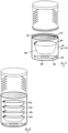
- Figures 1a, 1b and 1c show a comparative container 2.
- the container comprises a mixing chamber 4 (shown in Figure 1a ) which is generally tubular in shape and which is open at both ends 6, 8.
- the mixing chamber 4 is blow-molded from a polymeric material.
- the mixing chamber 4 includes a central circular bellows 10, wherein the circular bellows 10 is formed from a number of bellows wall sections, which, in turn are formed from first conical wall portions 12, second conical wall portions 14 and outer return portions 16.
- the length of the first conical wall portions 12 is greater than the length of the second conical wall portions 14.
- Each bellows wall section is connected to adjacent or neighbouring bellows wall sections via respective inner return portions 18.
- the bellows wall sections are shown in more detail in Figure 2a .
- the inner return portions 18 include a semi-circular connecting portion, which prevents or minimises the deformation of the polymeric material beyond its elastic limit.
- Figure 1b shows a detachable closure element 20 in the form of a screw-on lid.
- the lid includes a downwardly extending skirt 22, which defines a threaded portion (not shown) on the inwardly facing wall of the skirt 22.
- the top end 6 of the mixing chamber 4 carries a complementary threaded portion 24, such that the closure element 20 may be screwed onto or unscrewed from the open top end 6 of the mixing chamber 4.
- Figure 1c shows a storage chamber defined by a storage chamber body 26.
- the storage chamber body 26 includes a cylindrical side wall 28, a closed bottom wall (not shown) and an upwardly extending skirt 30.
- the skirt 30 defines a threaded portion (not shown) on its inwardly facing wall.
- the bottom end 8 of the mixing chamber 4 carries a complementary threaded portion 32, such that the storage chamber body 26 may be screwed onto or unscrewed from the open bottom end 8 of the mixing chamber 4.
- a top wall of the storage chamber body 26 defines an opening 33 to provide access to the interior of the storage chamber, and the opening 33 is closed via a removable sealing film 34.
- the sealing film 34 is adhered or welded to a peripheral portion of the top wall which defines the opening 33.
- the container 2 is assembled by screwing the storage chamber body 26 to the open bottom end 8 of the mixing chamber 4 and by screwing the closure element 20 to the open top end of the mixing chamber 4.
- a concentrated product (not shown), for example a flavoured powder for forming a flavoured drink, is located within the sealed storage chamber 26.
- Figure 2a shows a section of the circular bellows 10 in an expanded configuration.
- the angle between the first conical wall portion 12 and the second conical wall portion 14 at the outer return portion 16 is about 90°.
- the angle between adjacent second conical wall portions 14 and first conical wall portions 12 at the inner return portion 18 is about 80°.
- Figure 2b shows the over-centre arrangement of the first and second wall portions 12, 14 in the collapsed configuration.
- the dashed line A in Figures 2a and 2b projects through a common point (an outer return portion 16).
- both of the inner return portions 18 are displaced vertically upwards as the mixing chamber 4 is collapsed until both of these inner return portions are located above the dashed line A.
- the displacement of the inner return portion 18 such that it lies outside of the cylindrical region defined between the two adjacent outer return portions 16 is referred to herein as an "over-centre" arrangement.
- Such an arrangement generates a latching force at each of the inner return portions 18 which are greater than the restorative forces that are stored in the return portions when the mixing chamber 4 is collapsed. Accordingly, the latching forces resist or prevent the expansion of the mixing chamber towards is expanded configuration.
- Figure 3 shows the comparative container 2 in its collapsed configuration. This is the typical configuration for storage or transportation of the container 2.
- the user first unscrews the storage chamber body 26 from the mixing chamber 4. This releases the air tight seal between the storage chamber body 26 and the mixing chamber 4 and prevents the generation of a partial vacuum within the mixing chamber during expansion.
- the mixing chamber is then expanded by urging the two end 6, 8 apart. Once expanded, the sealing film 34 is removed to expose the powdered concentrate product located within the storage chamber.
- the storage chamber body 26 is then screwed back onto the mixing chamber 4.
- the closure element 20 is then unscrewed from the top 6 of the mixing chamber 4 and a diluent (such as water) is added to the mixing chamber via the open end 6 of the mixing chamber 4.
- a diluent such as water
- the closure element 20 is then screwed back onto the top end 6 of the mixing chamber 4 and the concentrated powdered product is mixed with the diluent, for example with agitation or shaking.
- the circular bellows arrangement aids with the mixing of the concentrated powdered product and the diluent.
- the concentrated product within the storage chamber defined by the storage chamber body 26 may be in the form of a liquid, paste or gel, instead of a powder.
- Figures 4 and 5 show alternative comparative containers in which the mixing chamber 4 and the closure element 20 are as described above in connection with Figures 1 to 3 , but the storage chamber is different.
- a storage chamber body 40 includes a cylindrical side wall 42, an upwardly extending skirt 44, and a closed, gas-tight and liquid-tight top wall 46.
- a bottom wall 48 of the storage chamber body 40 defines an opening 50 and includes a detachable base 52 which is arranged to form a snap-fit with the bottom wall 48. In this way, the opening may be selectively closed or opened via the detachable base 52.
- the detachable base 52 may include a circular aperture through which a user's finger may be located to permit a downward force to be exerted on the detachable base 52.
- the concentrated product is located within a separate sealed housing 54 which includes an opening at its upper end that is sealed with a sealing film 56.
- Figure 5 shows a similar arrangement to that shown in Figure 4 and described above, except that the cylindrical side wall is longer and a plurality of sealed housings 60 containing separate concentrated products are located within the storage chamber defined by the storage chamber body.
- the concentrated products in the sealed housings 60 may be the same or different. All other features of the storage chamber body are as described above in connection with Figure 4 .
- the user removes the closure element from the top of the mixing chamber and expands the mixing chamber as described above.
- the detachable base is then removed from bottom wall and the or one of the individually sealed housings are removed from the storage chamber.
- the sealing film is then removed from the housing and the concentrated product is emptied into the mixing chamber.
- a diluent, such as water is then added to the mixing chamber, the closure element is then screwed back onto the top open end of the mixing chamber and the concentrated product mixed with the diluent.
- the diluent may be added to the mixing chamber first and the concentrated product added to the diluent in the mixing chamber.
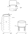
- a container 102 includes a closure element 120, which in turn includes a storage chamber body 126.
- the container 102 further includes a mixing chamber 104 comprising an open top end 106, a closed bottom end 108 and a circular bellows 110 as described above in connection with the circular bellows 10.
- the closure element 120 includes an upper element body 120a from which the storage chamber body 126 depends. From around the periphery of the upper element body 120a depends a skirt 122, which defines a threaded portion 122a on the inwardly facing wall of the skirt 122.
- the top end 106 of the mixing chamber 104 carries a threaded portion 124 which is complementary to the threaded portion 122a of the closure element 120.
- the storage chamber body 126 is open at its bottom end and includes a sealing film 134 adhered to or welded to the storage chamber body which maintains the concentrated product within the storage chamber defined within the storage chamber body 126.
- Figure 7 shows the container 102 in its collapsed configuration. It will be noted that in this configuration, the storage chamber body 126 is located within the mixing chamber 104.
- a user follows similar steps to this described above.
- the closure element 120 is first unscrewed from the open top end 106 of the mixing chamber 104 and the circular bellows of the mixing chamber are urged into their expanded configuration.
- the sealing film 134 is removed from the bottom of the storage chamber body 126 and the concentrated product is mixed with a diluent within the mixing chamber 104 and agitated after the closure element 120 has been screwed back onto the open top 106 of the mixing chamber 104.
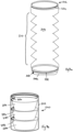
- Figures 8a and 8b show a further comparative container, which is similar to the container shown in Figure 5 , except that mixing chamber is closed at its bottom end.
- Figures 8a and 8b show a container 202 which includes a mixing chamber 204 that is open at its top end 206 and closed at its bottom end 208 with a sealing wall 208a.
- the top end 206 of the mixing chamber 204 carries a threaded element 224 and a closure element (not shown) is provided which is the same as described above in connection with Figure 1b .
- the mixing chamber includes circular bellows 210 which are as described above in connection with Figures 1a, 2a and 2b .
- the storage chamber of this container is similar to that described above in connection with Figure 5 , except that the storage chamber is closed at its bottom end and open at its top end.
- the container 202 includes a storage chamber body 240 which includes a cylindrical body 242 which is closed at its bottom end 248 and open at its top end 246. On an inwardly facing surface of the top end 246 is carried a threaded element 244.
- the storage chamber includes a plurality of sealed housings 254, each of which is sealed via a respective sealing film 256.
- a concentrated product is located within each of the housings.
- the housings may instead comprise sachets which contain the concentrated product.
- the storage chamber body 240 need simply be unscrewed from the mixing chamber 204 and one of the housings 254 removed from the storage chamber.
- the concentrated product located within the housing may then be mixed with a diluent as described above.
- Figures 9 and 10 show a further embodiment of the invention which is similar to the embodiment shown in Figures 6a, 6b and 7 .
- a mixing chamber is provided which is identical to the mixing chamber 104 described above in connection with Figures 6a, 6b and 7 .
- a closure element 320 is provided in order to close the open top end of the mixing chamber 104.
- the closure element 320 includes a circular top wall 320a and a skirt 322 which depends downwards from a peripheral edge portion of the top wall 320a.
- the skirt 322 carries a threaded element 322a
- a storage chamber body 326 depends downwards from a central portion of the top wall 320a.
- the storage chamber body 326 comprises a cylindrical wall 328 which is closed at its bottom by a sealing wall 330.
- the storage chamber body 326 is open at its top end 332.
- the opening is selectively closed by a snap-fit lid 334, which forms a snap fit with the circular top wall 320a.
- the snap-fit lid 334 may include a circular aperture through which a user's finger may be located to permit an upward force to be exerted on the snap-fit lid 334 in order to remove it.
- the storage chamber defined by the storage chamber body includes a plurality of sealed housings 354, each of which is sealed via a respective sealing film 356.
- a concentrated product is located within each of the housings.
- the housings may instead comprise sachets which contain the concentrated product.
- a user uses the container in much the same way as described above: the snap-fit lid 334 is removed and one of the housings 354 is removed from the storage chamber defined by the storage chamber body 326. The snap-fit lid 334 is then replaced. The closure element 320 is unscrewed from the mixing chamber 104 and the concentrated product from the housing 354 and a diluent are added to the mixing chamber 104. The closure element 320 is then screwed back onto the mixing chamber and the concentrated product is mixed with the diluent.
- FIG. 11 and 12 A final comparative container is shown in Figures 11 and 12 , which is similar to the container shown in Figures 1a, b, 1c and 3 .
- Figures 11 and 12 show a container 402.
- the container 402 comprises a mixing chamber 404 which is identical to the mixing chamber 4 shown in Figure 1a and which is open at both ends 406, 408.
- the container 402 further includes a closure element 420 in the form of a screw-on lid.
- the lid 420 includes a downwardly extending skirt 422, which defines a threaded portion (not shown) on the inwardly facing wall of the skirt 422.
- the top end 406 of the mixing chamber 404 carries a complementary threaded portion 424, such that the closure element 420 may be screwed onto or unscrewed from the open top end 406 of the mixing chamber 404.
- the container 402 also includes a storage chamber defined by a storage chamber body 426.
- the storage chamber body 426 includes a base portion 427 upwardly from which extends a cylindrical storage portion formed from a cylindrical side wall 428, which has a closed top 428a and an open bottom 428b. Upwardly extending from a peripheral edge portion of the base portion 427 is a skirt 430.
- the skirt 430 carries a threaded portion 430a on its inwardly facing wall.
- the bottom end 408 of the mixing chamber 404 carries a complementary threaded portion 432, such that the storage chamber body 426 may be screwed onto or unscrewed from the open bottom end 408 of the mixing chamber 404.
- the storage chamber body 426 further includes a snap-fit plug 452 which selectively closes or opens the open bottom end 428b of the cylindrical storage portion.
- the snap-fit plug 452 may include a circular aperture through which a user's finger may be located to permit an downward force to be exerted on the snap-fit plug 452 in order to remove it.
- the storage chamber defined by the storage chamber body 426 includes a plurality of sealed housings 454, each of which is sealed via a respective sealing film 456.
- a concentrated product is located within each of the housings 454.
- the housings may instead comprise sachets which contain the concentrated product.
- the container 402 is assembled by screwing the storage chamber body 426 to the open bottom end 408 of the mixing chamber 404 and by screwing the closure element 420 to the open top end 406 of the mixing chamber 404.
- a user uses the container in much the same way as described above: the snap-fit plug 452 is removed and one of the housings 354 is removed from the cylindrical storage portion. The snap-fit plug 452 is then replaced.
- the closure element 420 is unscrewed from the mixing chamber 404 and the concentrated product from the housing 454 and a diluent are added to the mixing chamber 404. The closure element 420 is then screwed back onto the mixing chamber and the concentrated product is mixed with the diluent.
- the storage chamber body 426 need not be unscrewed from the mixing chamber 404 in order to use the container 402 in this comparative example.
Landscapes
- Engineering & Computer Science (AREA)
- Mechanical Engineering (AREA)
- Ceramic Engineering (AREA)
- Package Specialized In Special Use (AREA)
- Medical Preparation Storing Or Oral Administration Devices (AREA)
Description
- The present invention relates to a container and, in particular, to a collapsible container that is capable of containing a concentrated product.
- Collapsible containers are known and are described, for example, in
US4,773,458 ;US4,955,493 ; andUS4,492,313 . In addition,US5,114,011 ;US5,384,138 ;US7,866,500 ; andFR1 016 601 - However, the known collapsible containers have been in the form of a collapsible tube which defines a single chamber.
- According to a first aspect of the invention, there is provided a container as defined in the claims appended hereto.
- The container of the invention defines two separate chambers: a storage chamber within which at least one concentrated product may be located; and a mixing chamber within which the concentrated product may be mixed with a diluent, such as water.
- The circular bellows of the mixing chamber permit the container to be configured in a collapsed configuration when there is little or no diluent in the mixing chamber. This makes the container easier to store and transport. However, when it is desired to dilute the concentrated product, the mixing chamber may be expanded to receive the desired volume of diluent.
- By storing the concentrated product in the storage chamber, the shelf life of the concentrated product may be significantly increased compared to a concentrated product simply located within the mixing chamber. This is because the polymeric material from which the mixing chamber may be formed in order to permit the collapsing and the expansion of the mixing chamber via its circular bellows may not provide optimum protection for the concentrated product against spoiling. In contrast, the storage chamber within which the concentrated product is located may provide the desired protection against spoiling without interfering with the operation of the container.
- Furthermore, the circular bellows of the mixing chamber increases the agitation when the diluent is added to the concentrated product, which aids the mixing of the concentrated product with the diluent.
- In the context of the present invention, the concentrated product may be in the form of a liquid, a gel or a solid, such as a powder or a tablet. Furthermore, the diluent is suitably water.
- The mixing chamber is suitably defined by a mixing chamber body.
- The circular bellows includes a latching arrangement which acts to latch the bellows in its collapsed and/or expanded configuration. It will be understood that in the context of the subject invention, the latching arrangement resists the movement of the bellows. In other words, the force exerted by the latching arrangement is greater than a stored force within the bellows which would otherwise urge the bellows out of its collapsed and/or expanded configuration. The latching arrangement does not prevent movement of the bellows. Instead, the latching force exerted by the latching arrangement must first be removed or overcome in order to move the bellows against the latching force.
- According to the invention, the mixing chamber is detachably coupled to the storage container. For example, the storage chamber may be screwed onto the mixing chamber or it may be snap-fit to the mixing chamber. As such, the mixing chamber and the storage container may include a threaded coupling or a snap-fit coupling.
- In an embodiment of the invention, the closure element defines a well which is configured to receive a housing or container which contains the concentrated product. The closure element suitably includes an internally facing surface and an externally facing surface and the well may be open at the externally facing surface. The well may be an open well or it may include a closable lid.
- The well may define the storage chamber or it may define a holding chamber separate to the storage chamber.
- In one embodiment of the invention, the storage chamber may be defined by a storage chamber body. In an alternative embodiment, the storage chamber may be defined within the closure element. In embodiments in which the storage chamber is defined by a storage chamber body, the body may be separate from the closure element.
- In embodiments in which the storage chamber is defined by a storage chamber body, the storage chamber body may be coupled to the second end of the mixing chamber (i.e. the end of the mixing chamber which is opposite to the first end). The coupling between storage chamber body and the mixing chamber may be a releasable or reversible coupling, such as a threaded coupling or a snap-fit coupling. This permits the mixing chamber to be filled with a diluent without having to remove the storage chamber body from the mixing chamber.
- The second end of the mixing chamber is closed. It will be appreciated in the context of the subject invention that the term "closed" means that the relative end forms a liquid-tight seal with the mixing chamber body, wherein the mixing chamber body, including the closed end, being formed by a continuous layer of moulded polymeric material. This means that the storage chamber need have no sealing function in respect of the mixing chamber. Accordingly, the storage chamber body need not form a liquid-tight seal with the mixing chamber when coupled thereto.
- In such embodiments, the storage chamber body may define a closable opening for access to the storage chamber and the concentrated product located therein. The closable opening may be defined at any suitable location of the storage chamber body.
- As noted above, the storage chamber may be defined by the closure element or it may be carried by the closure element. For example, the storage chamber may be defined within the closure element.
- The closure element may define a tubular side wall having a top end and a bottom end opposite to the top end; wherein the side wall, top end and bottom end together define the storage chamber; and wherein a closable opening is defined in the bottom end.
- The skilled person will understand that reference to "top" and "bottom" refer to the container when oriented in a substantially vertical orientation with the closure element located at the top of the mixing chamber.
- By locating the closable opening in the bottom end of the storage chamber, the interior of the chamber may only be accessed when the closure element has been removed from the mixing chamber. Additionally, it permits a more compact arrangement, as the tubular side wall may extend wholly or partially into the interior of the mixing chamber.
- In alternative embodiments, the closure element defines a tubular side wall having a top end and a bottom end opposite to the top end; wherein the side wall, top end and bottom end together define the storage chamber; and wherein a closable opening is defined in the top end. In this arrangement, the interior of the storage chamber may be accessed without removing the closure element from the mixing chamber.
- The closure element is suitably releasably secured to the mixing chamber via a threaded coupling.
- The mixing chamber is suitably in the form of a substantially tubular body.
- In an embodiment of the invention, the storage chamber contains one or more concentrated products, wherein each concentrated product is stored within a respective housing. For example, the storage chamber may contain a plurality of separate concentrated products, each stored within a respective housing. The housings are suitable sealed against the ingress of gases and liquids.
- The circular bellows are defined by a series of circular bellows wall sections (i.e. a plurality of bellows wall sections arranged in a longitudinal array), wherein each circular bellows wall section includes a first wall portion and a second wall portion; the first and second wall portions are conical sections which are angled relative to each other; the first and second wall portions extend outwardly from the longitudinal axis of the mixing chamber and together define a V-shape; the connection between the first and second wall portions forms an outer return portion; and adjacent bellows wall sections are connected via inner return portions.
- The skilled person will appreciate that reference to "V-shaped" is to be understood to a sideways V, in other words the outer return is ">"-shaped. In this way, as the container is collapsed, the angle between first and second wall portions of each bellows wall section will decrease and as the container is expanded, the angle between the first and second wall portions of each bellows wall section will increase.
- The skilled person will understand that the angle between the first and second wall portions of each bellows wall section may range from 0° to 180°. However, this angle is suitably from 0° to 120°, 110°, 100° or 90°.
- This arrangement of the bellows wall sections permits the maximum expansion and collapse of the bottle while maintaining a desired level of mechanical strength and resistance to cracking.
- The inner return portions may include an arcuate connecting portion. In other words, a first or second wall portion of a bellows wall section is connected to a second or first wall portion of a neighbouring (i.e. adjacent) bellows wall section via an arcuate connecting body, such as a semi-circular connecting body. Without wishing to be bound by theory, it is believed that the arcuate connecting portion is more resistant to cracking and permits the adjacent wall portions to hinge relative to each other with less strain. This may be because the bottle material is not weakened at the inner return portions by fracturing as the plastic material is not deformed beyond its elastic limit.
- In such embodiments, the second wall portion may be shorter than the first wall portion in each of the bellows wall sections. The arrangement causes an "over-centre" arrangement when the mixing chamber is moved to its collapsed configuration, which in turn latches the circular bellows in their collapsed configuration. Thus, in such embodiments, a latching mechanism is formed by second wall portions being shorter than the first wall portions, resulting in an over-centre arrangement of the inner return portions in the collapsed configuration. The over-centre arrangement results when an inner return portion located between a pair of outer return portions is displaced longitudinally during the compression of the mixing chamber such that after compression, the inner return portion has been displaced vertically above or below both of the pair of outer return portions either side of the inner return portion (on the basis that the mixing chamber is collapsed in a vertical direction). This "over-centre" arrangement generates latching forces in the circular bellows portion that are typically greater than the restorative forces stored in the return portions as a result of the collapsing of the mixing chamber and therefore prevents or resists the restorative forces urging the mixing chamber back to its expanded configuration.
- Accordingly, when the mixing chamber is urged into its collapsed configuration, it will typically remain in that configuration until it is urged into its expanded configuration. The expansion force exerted on the mixing chamber will overcome the latching forces of the bellows wall sections.
- The skilled person will appreciate that the features described and defined in connection with the aspect of the invention and the embodiments thereof may be combined in any combination, regardless of whether the specific combination is expressly mentioned herein. Thus, all such combinations are considered to be made available to the skilled person.
- An embodiment of the invention will now be described, by way of example only, with reference to the accompanying drawings as follows.
-
-
Figures 1a, 1b and 1c are perspective views of a comparative container in exploded form; -
Figures 2a and 2b show a section of the inner and outer return portions of the mixing chamber in expanded and collapsed configurations; -
Figure 3 shows the container ofFigures 1a, 1b and 1c in a collapsed configuration; -
Figure 4 shows a further comparative in its collapsed configuration; -
Figure 5 shows a further comparative container in its collapsed configuration; -
Figures 6a and 6b show a container according to a first embodiment of the invention in an expanded configuration; -
Figure 7 shows the container ofFigures 6a and 6b in its collapsed configuration; -
Figures 8a and 8b show a further comparative container in an expanded configuration; -
Figure 9 shows a container according to a second embodiment of the invention in an expanded configuration; -
Figure 10 shows the container ofFigure 9 in its collapsed configuration; -
Figure 11 shows a comparative container in an expanded configuration; and -
Figure 12 shows the container ofFigure 11 in its collapsed configuration. - For the avoidance of doubt, the skilled person will appreciate that in this specification, the terms "up", "down", "front", "rear", "upper", "lower", "width", etc. refer to the orientation of the components as found in the example when installed for normal use as shown in the Figures.
-
Figures 1a, 1b and 1c show acomparative container 2. The container comprises a mixing chamber 4 (shown inFigure 1a ) which is generally tubular in shape and which is open at both ends 6, 8. The mixing chamber 4 is blow-molded from a polymeric material. The mixing chamber 4 includes a central circular bellows 10, wherein the circular bellows 10 is formed from a number of bellows wall sections, which, in turn are formed from firstconical wall portions 12, secondconical wall portions 14 andouter return portions 16. The length of the firstconical wall portions 12 is greater than the length of the secondconical wall portions 14. - Each bellows wall section is connected to adjacent or neighbouring bellows wall sections via respective
inner return portions 18. The bellows wall sections are shown in more detail inFigure 2a . Theinner return portions 18 include a semi-circular connecting portion, which prevents or minimises the deformation of the polymeric material beyond its elastic limit. -
Figure 1b shows adetachable closure element 20 in the form of a screw-on lid. The lid includes a downwardly extendingskirt 22, which defines a threaded portion (not shown) on the inwardly facing wall of theskirt 22. The top end 6 of the mixing chamber 4 carries a complementary threadedportion 24, such that theclosure element 20 may be screwed onto or unscrewed from the open top end 6 of the mixing chamber 4. -
Figure 1c shows a storage chamber defined by a storage chamber body 26. The storage chamber body 26 includes acylindrical side wall 28, a closed bottom wall (not shown) and an upwardly extendingskirt 30. Theskirt 30 defines a threaded portion (not shown) on its inwardly facing wall. The bottom end 8 of the mixing chamber 4 carries a complementary threadedportion 32, such that the storage chamber body 26 may be screwed onto or unscrewed from the open bottom end 8 of the mixing chamber 4. A top wall of the storage chamber body 26 defines anopening 33 to provide access to the interior of the storage chamber, and theopening 33 is closed via aremovable sealing film 34. The sealingfilm 34 is adhered or welded to a peripheral portion of the top wall which defines theopening 33. - The
container 2 is assembled by screwing the storage chamber body 26 to the open bottom end 8 of the mixing chamber 4 and by screwing theclosure element 20 to the open top end of the mixing chamber 4. A concentrated product (not shown), for example a flavoured powder for forming a flavoured drink, is located within the sealed storage chamber 26. -
Figure 2a shows a section of the circular bellows 10 in an expanded configuration. As can be seen, the angle between the firstconical wall portion 12 and the secondconical wall portion 14 at theouter return portion 16 is about 90°. As the secondconical wall portion 14 is shorter than the firstconical wall portion 12, the angle between adjacent secondconical wall portions 14 and firstconical wall portions 12 at theinner return portion 18 is about 80°. -
Figure 2b shows the over-centre arrangement of the first andsecond wall portions Figures 2a and 2b projects through a common point (an outer return portion 16). As can be seen inFigure 2b , both of theinner return portions 18 are displaced vertically upwards as the mixing chamber 4 is collapsed until both of these inner return portions are located above the dashed line A. The displacement of theinner return portion 18 such that it lies outside of the cylindrical region defined between the two adjacentouter return portions 16 is referred to herein as an "over-centre" arrangement. Such an arrangement generates a latching force at each of theinner return portions 18 which are greater than the restorative forces that are stored in the return portions when the mixing chamber 4 is collapsed. Accordingly, the latching forces resist or prevent the expansion of the mixing chamber towards is expanded configuration. -
Figure 3 shows thecomparative container 2 in its collapsed configuration. This is the typical configuration for storage or transportation of thecontainer 2. Starting from this configuration, the user first unscrews the storage chamber body 26 from the mixing chamber 4. This releases the air tight seal between the storage chamber body 26 and the mixing chamber 4 and prevents the generation of a partial vacuum within the mixing chamber during expansion. The mixing chamber is then expanded by urging the two end 6, 8 apart. Once expanded, the sealingfilm 34 is removed to expose the powdered concentrate product located within the storage chamber. The storage chamber body 26 is then screwed back onto the mixing chamber 4. Theclosure element 20 is then unscrewed from the top 6 of the mixing chamber 4 and a diluent (such as water) is added to the mixing chamber via the open end 6 of the mixing chamber 4. Theclosure element 20 is then screwed back onto the top end 6 of the mixing chamber 4 and the concentrated powdered product is mixed with the diluent, for example with agitation or shaking. The circular bellows arrangement aids with the mixing of the concentrated powdered product and the diluent. - The skilled person will appreciate that the concentrated product within the storage chamber defined by the storage chamber body 26 may be in the form of a liquid, paste or gel, instead of a powder.
-
Figures 4 and 5 show alternative comparative containers in which the mixing chamber 4 and theclosure element 20 are as described above in connection withFigures 1 to 3 , but the storage chamber is different. - In
Figure 4 , astorage chamber body 40 includes acylindrical side wall 42, an upwardly extendingskirt 44, and a closed, gas-tight and liquid-tight top wall 46. Abottom wall 48 of thestorage chamber body 40 defines anopening 50 and includes adetachable base 52 which is arranged to form a snap-fit with thebottom wall 48. In this way, the opening may be selectively closed or opened via thedetachable base 52. To ease removal, thedetachable base 52 may include a circular aperture through which a user's finger may be located to permit a downward force to be exerted on thedetachable base 52. - As the
detachable base 52 does not form a gas-tight and liquid-tight seal with thebottom wall 48, the concentrated product is located within a separate sealedhousing 54 which includes an opening at its upper end that is sealed with a sealingfilm 56. -
Figure 5 shows a similar arrangement to that shown inFigure 4 and described above, except that the cylindrical side wall is longer and a plurality of sealedhousings 60 containing separate concentrated products are located within the storage chamber defined by the storage chamber body. In this embodiment, the concentrated products in the sealedhousings 60 may be the same or different. All other features of the storage chamber body are as described above in connection withFigure 4 . - In order to use the
comparative container 2 shown inFigures 4 and 5 , the user removes the closure element from the top of the mixing chamber and expands the mixing chamber as described above. The detachable base is then removed from bottom wall and the or one of the individually sealed housings are removed from the storage chamber. The sealing film is then removed from the housing and the concentrated product is emptied into the mixing chamber. A diluent, such as water is then added to the mixing chamber, the closure element is then screwed back onto the top open end of the mixing chamber and the concentrated product mixed with the diluent. - The skilled person will appreciate that in the containers shown in
Figures 4 and 5 , the diluent may be added to the mixing chamber first and the concentrated product added to the diluent in the mixing chamber. -
Figures 6a, 6b and 7 show an embodiment of the invention. In this embodiment, acontainer 102 includes aclosure element 120, which in turn includes astorage chamber body 126. In this embodiment, thecontainer 102 further includes a mixingchamber 104 comprising an opentop end 106, a closedbottom end 108 and a circular bellows 110 as described above in connection with the circular bellows 10. - The
closure element 120 includes anupper element body 120a from which thestorage chamber body 126 depends. From around the periphery of theupper element body 120a depends askirt 122, which defines a threaded portion 122a on the inwardly facing wall of theskirt 122. - The
top end 106 of the mixingchamber 104 carries a threadedportion 124 which is complementary to the threaded portion 122a of theclosure element 120. - The
storage chamber body 126 is open at its bottom end and includes asealing film 134 adhered to or welded to the storage chamber body which maintains the concentrated product within the storage chamber defined within thestorage chamber body 126. -
Figure 7 shows thecontainer 102 in its collapsed configuration. It will be noted that in this configuration, thestorage chamber body 126 is located within the mixingchamber 104. - In use, a user follows similar steps to this described above. The
closure element 120 is first unscrewed from the opentop end 106 of the mixingchamber 104 and the circular bellows of the mixing chamber are urged into their expanded configuration. The sealingfilm 134 is removed from the bottom of thestorage chamber body 126 and the concentrated product is mixed with a diluent within the mixingchamber 104 and agitated after theclosure element 120 has been screwed back onto theopen top 106 of the mixingchamber 104. -
Figures 8a and 8b show a further comparative container, which is similar to the container shown inFigure 5 , except that mixing chamber is closed at its bottom end. Thus,Figures 8a and 8b show a container 202 which includes a mixingchamber 204 that is open at its top end 206 and closed at itsbottom end 208 with a sealing wall 208a. - The top end 206 of the mixing
chamber 204 carries a threadedelement 224 and a closure element (not shown) is provided which is the same as described above in connection withFigure 1b . - The mixing chamber includes
circular bellows 210 which are as described above in connection withFigures 1a, 2a and 2b . - The storage chamber of this container is similar to that described above in connection with
Figure 5 , except that the storage chamber is closed at its bottom end and open at its top end. Accordingly, the container 202 includes astorage chamber body 240 which includes acylindrical body 242 which is closed at its bottom end 248 and open at its top end 246. On an inwardly facing surface of the top end 246 is carried a threaded element 244. - The threaded element 244 threaded engages with a corresponding threaded
element 232 carried by a lower portion of the mixingchamber 204. - The storage chamber includes a plurality of sealed
housings 254, each of which is sealed via arespective sealing film 256. A concentrated product is located within each of the housings. The skilled person will appreciate that instead of the housings comprising relatively rigid bodies closed with sealing films, the housings may instead comprise sachets which contain the concentrated product. - In this container, the
storage chamber body 240 need simply be unscrewed from the mixingchamber 204 and one of thehousings 254 removed from the storage chamber. The concentrated product located within the housing may then be mixed with a diluent as described above. -
Figures 9 and 10 show a further embodiment of the invention which is similar to the embodiment shown inFigures 6a, 6b and 7 . - In this embodiment, a mixing chamber is provided which is identical to the mixing
chamber 104 described above in connection withFigures 6a, 6b and 7 . In order to close the open top end of the mixingchamber 104, aclosure element 320 is provided. - The
closure element 320 includes a circular top wall 320a and askirt 322 which depends downwards from a peripheral edge portion of the top wall 320a. Theskirt 322 carries a threadedelement 322a - A
storage chamber body 326 depends downwards from a central portion of the top wall 320a. Thestorage chamber body 326 comprises acylindrical wall 328 which is closed at its bottom by a sealingwall 330. Thestorage chamber body 326 is open at itstop end 332. The opening is selectively closed by a snap-fit lid 334, which forms a snap fit with the circular top wall 320a. As noted above, the snap-fit lid 334 may include a circular aperture through which a user's finger may be located to permit an upward force to be exerted on the snap-fit lid 334 in order to remove it. - As with the preceding container, the storage chamber defined by the storage chamber body includes a plurality of sealed
housings 354, each of which is sealed via arespective sealing film 356. A concentrated product is located within each of the housings. The skilled person will appreciate that instead of the housings comprising relatively rigid bodies closed with sealing films, the housings may instead comprise sachets which contain the concentrated product. - As can be seen from
Figure 10 , when theclosure element 320 is screwed on the top end of the mixingchamber 104, thestorage chamber body 326 is located within the mixingchamber 104. This results in a very compact configuration in the collapsed configuration. - A user uses the container in much the same way as described above: the snap-
fit lid 334 is removed and one of thehousings 354 is removed from the storage chamber defined by thestorage chamber body 326. The snap-fit lid 334 is then replaced. Theclosure element 320 is unscrewed from the mixingchamber 104 and the concentrated product from thehousing 354 and a diluent are added to the mixingchamber 104. Theclosure element 320 is then screwed back onto the mixing chamber and the concentrated product is mixed with the diluent. - A final comparative container is shown in
Figures 11 and 12 , which is similar to the container shown inFigures 1a, b, 1c and 3 . -
Figures 11 and 12 show acontainer 402. Thecontainer 402 comprises a mixingchamber 404 which is identical to the mixing chamber 4 shown inFigure 1a and which is open at both ends 406, 408. - The
container 402 further includes aclosure element 420 in the form of a screw-on lid. Thelid 420 includes a downwardly extendingskirt 422, which defines a threaded portion (not shown) on the inwardly facing wall of theskirt 422. Thetop end 406 of the mixingchamber 404 carries a complementary threadedportion 424, such that theclosure element 420 may be screwed onto or unscrewed from the opentop end 406 of the mixingchamber 404. - The
container 402 also includes a storage chamber defined by astorage chamber body 426. Thestorage chamber body 426 includes abase portion 427 upwardly from which extends a cylindrical storage portion formed from acylindrical side wall 428, which has a closed top 428a and an open bottom 428b. Upwardly extending from a peripheral edge portion of thebase portion 427 is askirt 430. Theskirt 430 carries a threaded portion 430a on its inwardly facing wall. Thebottom end 408 of the mixingchamber 404 carries a complementary threadedportion 432, such that thestorage chamber body 426 may be screwed onto or unscrewed from the openbottom end 408 of the mixingchamber 404. - The
storage chamber body 426 further includes a snap-fit plug 452 which selectively closes or opens the open bottom end 428b of the cylindrical storage portion. As noted above, the snap-fit plug 452 may include a circular aperture through which a user's finger may be located to permit an downward force to be exerted on the snap-fit plug 452 in order to remove it. - As with the preceding embodiment, the storage chamber defined by the
storage chamber body 426 includes a plurality of sealedhousings 454, each of which is sealed via arespective sealing film 456. A concentrated product is located within each of thehousings 454. The skilled person will appreciate that instead of the housings comprising relatively rigid bodies closed with sealing films, the housings may instead comprise sachets which contain the concentrated product. - The
container 402 is assembled by screwing thestorage chamber body 426 to the openbottom end 408 of the mixingchamber 404 and by screwing theclosure element 420 to the opentop end 406 of the mixingchamber 404. - As can be seen from
Figure 12 , when thestorage chamber body 426 is screwed on thebottom end 408 of the mixingchamber 404, the cylindrical storage portion is located within the mixingchamber 404. This results in a very compact configuration in the collapsed configuration. - A user uses the container in much the same way as described above: the snap-
fit plug 452 is removed and one of thehousings 354 is removed from the cylindrical storage portion. The snap-fit plug 452 is then replaced. Theclosure element 420 is unscrewed from the mixingchamber 404 and the concentrated product from thehousing 454 and a diluent are added to the mixingchamber 404. Theclosure element 420 is then screwed back onto the mixing chamber and the concentrated product is mixed with the diluent. - It will be noted that the
storage chamber body 426 need not be unscrewed from the mixingchamber 404 in order to use thecontainer 402 in this comparative example.
Claims (10)
- A container (102) including a storage chamber (126, 326) within which is located at least one concentrated product; a mixing chamber (104) coupled to the storage chamber (126, 326); and a closure element (120, 320), wherein the storage chamber (126, 326) is isolated from the mixing chamber (104); the mixing chamber (104) is defined by a body having a longitudinal length defined between opposed first (106) and second (108) ends and along at least a portion of the length of the mixing chamber, the body defines circular bellows (110), such that the mixing chamber has a collapsed configuration when the ends (106, 108) of the body are urged together and an expanded configuration when the ends of the body are urged apart; wherein the bellows further including a latching arrangement which acts to latch the bellows in their collapsed configuration and/or their expanded configuration; wherein a first end (106) of the mixing chamber is open and is selectively closable via the closure element (120, 320); wherein the second end (108) of the mixing chamber is closed via a wall which forms part of the mixing chamber body; and wherein the mixing chamber (104) is detachably coupled to the storage chamber (126, 326) via a screw coupling or a snap fit coupling; characterised in that the circular bellows (110) are defined by a series of bellows wall sections, wherein each bellows wall section includes a first wall portion (12) and a second wall portion (14); the first and second wall portions (12, 14) are conical sections which are angled relative to each other; the first and second wall portions (12, 14) extend outwardly from the longitudinal axis of the mixing chamber (104) and together define a V-shape; the connection between the first and second wall portions (12, 14) forms an outer return portion (16); and adjacent bellows wall sections are connected via inner return portions (18).
- A container (102) according to Claim 1, wherein the closure element (120, 320) defines a well which is configured to receive a container (354) which contains the concentrated product.
- A container (102) according to Claim 2, wherein the closure element (120, 320) includes an internally facing surface and an externally facing surface and the well is open at the externally facing surface.
- A container (102) according to any of Claims 1 to 3, wherein the storage chamber (126, 326) is defined by a storage chamber body.
- A container (102) according to Claim 4, wherein the storage chamber body is coupled to the second end of the mixing chamber.
- A container (102) according to any of Claims 1 to 5, wherein the storage chamber (126, 326) or a further storage chamber is defined within the closure element (120, 320).
- A container (102) according to Claim 6, wherein the closure element (120, 320) defines a tubular side wall having a top end and a bottom end opposite to the top end; and wherein a closable opening is defined in the bottom end, optionally wherein at least a portion of the storage chamber extends into the mixing chamber (104) when the closure element (120, 320) is coupled to the mixing chamber (104).
- A container (102) according to Claim 6, wherein the closure element (120, 320) defines a tubular side wall (328) having a top end and a bottom end opposite to the top end; and wherein a closable opening (332) is defined in the top end.
- A container (102) according to any of Claims 1 to 8, wherein the closure element (120, 320) is threadedly coupled to the mixing chamber (104).
- A container (102) according to Claim 1, wherein the latching arrangement is formed by the second wall portion (14) being shorter than the first wall portion (12) in each of the bellows wall sections, whereby each inner return portion (18) forms an over-centre arrangement in the collapsed configuration.
Applications Claiming Priority (1)
| Application Number | Priority Date | Filing Date | Title |
|---|---|---|---|
| US201962859973P | 2019-06-11 | 2019-06-11 |
Publications (2)
| Publication Number | Publication Date |
|---|---|
| EP3750819A1 EP3750819A1 (en) | 2020-12-16 |
| EP3750819B1 true EP3750819B1 (en) | 2023-11-22 |
Family
ID=71069702
Family Applications (1)
| Application Number | Title | Priority Date | Filing Date |
|---|---|---|---|
| EP20178628.2A Revoked EP3750819B1 (en) | 2019-06-11 | 2020-06-05 | A container |
Country Status (3)
| Country | Link |
|---|---|
| US (2) | US20200391929A1 (en) |
| EP (1) | EP3750819B1 (en) |
| ES (1) | ES2972354T3 (en) |
Families Citing this family (1)
| Publication number | Priority date | Publication date | Assignee | Title |
|---|---|---|---|---|
| CN218752056U (en) * | 2022-08-10 | 2023-03-28 | 刘锋 | Storage unit, cover body and container |
Citations (6)
| Publication number | Priority date | Publication date | Assignee | Title |
|---|---|---|---|---|
| FR1016601A (en) | 1952-11-18 | |||
| US4955493A (en) | 1989-08-15 | 1990-09-11 | Touzani William N | Collapsible expansible plastic hollow articles in a latchable configuration |
| US20100219189A1 (en) | 2007-08-28 | 2010-09-02 | Prontopharma-Europe S.R.L. | Retractable and flexible plastic container for liquids |
| US7866500B1 (en) | 2007-08-30 | 2011-01-11 | John David Peggs | Collapsible polymeric bellows storage tube |
| WO2013114078A1 (en) | 2012-01-31 | 2013-08-08 | Team Grasshopper Ltd | Packaging containing a consumable |
| WO2018087558A1 (en) | 2016-11-11 | 2018-05-17 | Oribiotech Ltd | Cell culture device system and methods of use thereof |
Family Cites Families (15)
| Publication number | Priority date | Publication date | Assignee | Title |
|---|---|---|---|---|
| US2978132A (en) * | 1960-03-07 | 1961-04-04 | Knapp Monarch Co | Jug closure |
| DE3344345A1 (en) * | 1983-12-08 | 1985-06-13 | Henkel KGaA, 4000 Düsseldorf | Fluid material disposable package |
| US4776972A (en) * | 1984-04-04 | 1988-10-11 | Purex Corporation | Adjustable strength laundry bleaching using a two compartment package |
| US4492313A (en) | 1984-05-29 | 1985-01-08 | William Touzani | Collapsible bottle |
| US4773458A (en) * | 1986-10-08 | 1988-09-27 | William Touzani | Collapsible hollow articles with improved latching and dispensing configurations |
| US5002193A (en) * | 1989-08-15 | 1991-03-26 | Touzani William N | Collapsible hollow articles with latching configuration and attached handle |
| US5114011A (en) * | 1990-08-31 | 1992-05-19 | Robbins Edward S Iii | Container assemblies with additive cups |
| US5384138A (en) * | 1990-08-31 | 1995-01-24 | Edward S. Robbins, III | Collapsible containers |
| US5348173A (en) * | 1991-09-20 | 1994-09-20 | Norwood Peter M | Collapsible-stackable plastic container |
| US5524788A (en) * | 1994-06-10 | 1996-06-11 | The Coca-Cola Company | Closure with hidden-gift compartment |
| US5769263A (en) * | 1997-01-21 | 1998-06-23 | Alcoa Closure Systems International, Inc. | Compartmentalized top cover promotional closure |
| WO2000043276A1 (en) * | 1999-01-20 | 2000-07-27 | Scott Brown | Collapsible fluid containers |
| DE202014101048U1 (en) * | 2014-03-10 | 2014-06-30 | Sam Tung Tsui | Foldable multipurpose containers |
| SE540078C2 (en) * | 2016-02-26 | 2018-03-13 | Ziiip Bottles Ab | A shaker bottle comprising a container for storing a powder supplement |
| KR20200002448U (en) * | 2019-04-30 | 2020-11-09 | 정병두 | Double bottle |
-
2020
- 2020-06-05 ES ES20178628T patent/ES2972354T3/en active Active
- 2020-06-05 US US16/893,596 patent/US20200391929A1/en not_active Abandoned
- 2020-06-05 EP EP20178628.2A patent/EP3750819B1/en not_active Revoked
-
2022
- 2022-03-22 US US17/701,003 patent/US20220212854A1/en not_active Abandoned
Patent Citations (6)
| Publication number | Priority date | Publication date | Assignee | Title |
|---|---|---|---|---|
| FR1016601A (en) | 1952-11-18 | |||
| US4955493A (en) | 1989-08-15 | 1990-09-11 | Touzani William N | Collapsible expansible plastic hollow articles in a latchable configuration |
| US20100219189A1 (en) | 2007-08-28 | 2010-09-02 | Prontopharma-Europe S.R.L. | Retractable and flexible plastic container for liquids |
| US7866500B1 (en) | 2007-08-30 | 2011-01-11 | John David Peggs | Collapsible polymeric bellows storage tube |
| WO2013114078A1 (en) | 2012-01-31 | 2013-08-08 | Team Grasshopper Ltd | Packaging containing a consumable |
| WO2018087558A1 (en) | 2016-11-11 | 2018-05-17 | Oribiotech Ltd | Cell culture device system and methods of use thereof |
Non-Patent Citations (3)
| Title |
|---|
| ANONYMOUS: "Anuga taste Innovation Show: The top innovations of 2019", ANUGA TASTE INNOVATION SHOW; OCTOBER 05-09, 2019, ANUGA TASTE, 3 October 2024 (2024-10-03) - 9 October 2019 (2019-10-09), pages 1 - 6, XP093211445, Retrieved from the Internet <URL:https://taste.anuga.de/en.php> |
| ANONYMOUS: "Catalogue Popit 2", POPITAGAIN VISION, 3 October 2024 (2024-10-03), pages 1 - 19, XP093211447, Retrieved from the Internet <URL:https://www.popitagain.com/wp-content/uploads/2022/10/cataloguepopit2.pdf> |
| POPITAGAIN LTD: "VIDÉO 03 PopitAgain LTD PopitAgain.com", 27 December 2019 (2019-12-27), XP093211450, Retrieved from the Internet <URL:https://www.youtube.com/watch?v=2EK47uSdx18> |
Also Published As
| Publication number | Publication date |
|---|---|
| US20200391929A1 (en) | 2020-12-17 |
| EP3750819A1 (en) | 2020-12-16 |
| US20220212854A1 (en) | 2022-07-07 |
| ES2972354T3 (en) | 2024-06-12 |
Similar Documents
| Publication | Publication Date | Title |
|---|---|---|
| US4805799A (en) | Container with unitary bladder | |
| US5333761A (en) | Collapsible bottle | |
| US4925055A (en) | Container with unitary bladder and associated dispenser cap | |
| KR100964999B1 (en) | Devices for storage and discharge of fluids | |
| JP5478413B2 (en) | 60 liter inner bag composite container and chemical discharge tube | |
| CA2218845A1 (en) | Collapsible container | |
| EP0611700A1 (en) | Container for a liquid | |
| CS264256B2 (en) | Device for liquid product delivering from a foldable reservoir | |
| WO1988005014A1 (en) | Foldable container for liquids which is self-locking in folded position | |
| US20090308867A1 (en) | Collapsible bottle | |
| EP3750819B1 (en) | A container | |
| US8061548B1 (en) | Segregation disk for a collapsible container | |
| US20080245789A1 (en) | Apparatus for a size adjustable container | |
| EP4177174B1 (en) | A filling module | |
| US20230257161A1 (en) | Segmented Shortwise Container Volume Apparatus | |
| EP1968865A1 (en) | Cap assembly with sectional storage chamber for secondary material | |
| AU2024204314B2 (en) | Sip and chug lid | |
| GB2314555A (en) | Intermediate bulk container with detachable funnel | |
| KR101800239B1 (en) | Container for recycling | |
| US12329300B2 (en) | Recyclable or reusable straw in container lid assembly | |
| AU4310493A (en) | A discharge for a transport or liquid container | |
| JPH09240732A (en) | Vessel for container | |
| JP2021084647A (en) | Container body, composite container body, and airless pump mounted to the container body | |
| US10835084B2 (en) | Liquid dispensing apparatus, system and method | |
| JP2019209994A (en) | Inverted double container |
Legal Events
| Date | Code | Title | Description |
|---|---|---|---|
| PUAI | Public reference made under article 153(3) epc to a published international application that has entered the european phase |
Free format text: ORIGINAL CODE: 0009012 |
|
| STAA | Information on the status of an ep patent application or granted ep patent |
Free format text: STATUS: THE APPLICATION HAS BEEN PUBLISHED |
|
| AK | Designated contracting states |
Kind code of ref document: A1 Designated state(s): AL AT BE BG CH CY CZ DE DK EE ES FI FR GB GR HR HU IE IS IT LI LT LU LV MC MK MT NL NO PL PT RO RS SE SI SK SM TR |
|
| AX | Request for extension of the european patent |
Extension state: BA ME |
|
| STAA | Information on the status of an ep patent application or granted ep patent |
Free format text: STATUS: REQUEST FOR EXAMINATION WAS MADE |
|
| 17P | Request for examination filed |
Effective date: 20210616 |
|
| RBV | Designated contracting states (corrected) |
Designated state(s): AL AT BE BG CH CY CZ DE DK EE ES FI FR GB GR HR HU IE IS IT LI LT LU LV MC MK MT NL NO PL PT RO RS SE SI SK SM TR |
|
| STAA | Information on the status of an ep patent application or granted ep patent |
Free format text: STATUS: EXAMINATION IS IN PROGRESS |
|
| 17Q | First examination report despatched |
Effective date: 20211118 |
|
| GRAP | Despatch of communication of intention to grant a patent |
Free format text: ORIGINAL CODE: EPIDOSNIGR1 |
|
| STAA | Information on the status of an ep patent application or granted ep patent |
Free format text: STATUS: GRANT OF PATENT IS INTENDED |
|
| INTG | Intention to grant announced |
Effective date: 20230605 |
|
| GRAS | Grant fee paid |
Free format text: ORIGINAL CODE: EPIDOSNIGR3 |
|
| GRAA | (expected) grant |
Free format text: ORIGINAL CODE: 0009210 |
|
| STAA | Information on the status of an ep patent application or granted ep patent |
Free format text: STATUS: THE PATENT HAS BEEN GRANTED |
|
| AK | Designated contracting states |
Kind code of ref document: B1 Designated state(s): AL AT BE BG CH CY CZ DE DK EE ES FI FR GB GR HR HU IE IS IT LI LT LU LV MC MK MT NL NO PL PT RO RS SE SI SK SM TR |
|
| REG | Reference to a national code |
Ref country code: GB Ref legal event code: FG4D |
|
| REG | Reference to a national code |
Ref country code: CH Ref legal event code: EP |
|
| REG | Reference to a national code |
Ref country code: DE Ref legal event code: R096 Ref document number: 602020021362 Country of ref document: DE |
|
| REG | Reference to a national code |
Ref country code: IE Ref legal event code: FG4D |
|
| REG | Reference to a national code |
Ref country code: LT Ref legal event code: MG9D |
|
| REG | Reference to a national code |
Ref country code: NL Ref legal event code: MP Effective date: 20231122 |
|
| PG25 | Lapsed in a contracting state [announced via postgrant information from national office to epo] |
Ref country code: GR Free format text: LAPSE BECAUSE OF FAILURE TO SUBMIT A TRANSLATION OF THE DESCRIPTION OR TO PAY THE FEE WITHIN THE PRESCRIBED TIME-LIMIT Effective date: 20240223 |
|
| PG25 | Lapsed in a contracting state [announced via postgrant information from national office to epo] |
Ref country code: IS Free format text: LAPSE BECAUSE OF FAILURE TO SUBMIT A TRANSLATION OF THE DESCRIPTION OR TO PAY THE FEE WITHIN THE PRESCRIBED TIME-LIMIT Effective date: 20240322 |
|
| PG25 | Lapsed in a contracting state [announced via postgrant information from national office to epo] |
Ref country code: LT Free format text: LAPSE BECAUSE OF FAILURE TO SUBMIT A TRANSLATION OF THE DESCRIPTION OR TO PAY THE FEE WITHIN THE PRESCRIBED TIME-LIMIT Effective date: 20231122 |
|
| REG | Reference to a national code |
Ref country code: AT Ref legal event code: MK05 Ref document number: 1633622 Country of ref document: AT Kind code of ref document: T Effective date: 20231122 |
|
| PG25 | Lapsed in a contracting state [announced via postgrant information from national office to epo] |
Ref country code: NL Free format text: LAPSE BECAUSE OF FAILURE TO SUBMIT A TRANSLATION OF THE DESCRIPTION OR TO PAY THE FEE WITHIN THE PRESCRIBED TIME-LIMIT Effective date: 20231122 |
|
| PG25 | Lapsed in a contracting state [announced via postgrant information from national office to epo] |
Ref country code: AT Free format text: LAPSE BECAUSE OF FAILURE TO SUBMIT A TRANSLATION OF THE DESCRIPTION OR TO PAY THE FEE WITHIN THE PRESCRIBED TIME-LIMIT Effective date: 20231122 |
|
| PG25 | Lapsed in a contracting state [announced via postgrant information from national office to epo] |
Ref country code: NL Free format text: LAPSE BECAUSE OF FAILURE TO SUBMIT A TRANSLATION OF THE DESCRIPTION OR TO PAY THE FEE WITHIN THE PRESCRIBED TIME-LIMIT Effective date: 20231122 Ref country code: LT Free format text: LAPSE BECAUSE OF FAILURE TO SUBMIT A TRANSLATION OF THE DESCRIPTION OR TO PAY THE FEE WITHIN THE PRESCRIBED TIME-LIMIT Effective date: 20231122 Ref country code: IS Free format text: LAPSE BECAUSE OF FAILURE TO SUBMIT A TRANSLATION OF THE DESCRIPTION OR TO PAY THE FEE WITHIN THE PRESCRIBED TIME-LIMIT Effective date: 20240322 Ref country code: GR Free format text: LAPSE BECAUSE OF FAILURE TO SUBMIT A TRANSLATION OF THE DESCRIPTION OR TO PAY THE FEE WITHIN THE PRESCRIBED TIME-LIMIT Effective date: 20240223 Ref country code: BG Free format text: LAPSE BECAUSE OF FAILURE TO SUBMIT A TRANSLATION OF THE DESCRIPTION OR TO PAY THE FEE WITHIN THE PRESCRIBED TIME-LIMIT Effective date: 20240222 Ref country code: AT Free format text: LAPSE BECAUSE OF FAILURE TO SUBMIT A TRANSLATION OF THE DESCRIPTION OR TO PAY THE FEE WITHIN THE PRESCRIBED TIME-LIMIT Effective date: 20231122 Ref country code: PT Free format text: LAPSE BECAUSE OF FAILURE TO SUBMIT A TRANSLATION OF THE DESCRIPTION OR TO PAY THE FEE WITHIN THE PRESCRIBED TIME-LIMIT Effective date: 20240322 |
|
| PG25 | Lapsed in a contracting state [announced via postgrant information from national office to epo] |
Ref country code: SE Free format text: LAPSE BECAUSE OF FAILURE TO SUBMIT A TRANSLATION OF THE DESCRIPTION OR TO PAY THE FEE WITHIN THE PRESCRIBED TIME-LIMIT Effective date: 20231122 Ref country code: RS Free format text: LAPSE BECAUSE OF FAILURE TO SUBMIT A TRANSLATION OF THE DESCRIPTION OR TO PAY THE FEE WITHIN THE PRESCRIBED TIME-LIMIT Effective date: 20231122 Ref country code: PL Free format text: LAPSE BECAUSE OF FAILURE TO SUBMIT A TRANSLATION OF THE DESCRIPTION OR TO PAY THE FEE WITHIN THE PRESCRIBED TIME-LIMIT Effective date: 20231122 Ref country code: NO Free format text: LAPSE BECAUSE OF FAILURE TO SUBMIT A TRANSLATION OF THE DESCRIPTION OR TO PAY THE FEE WITHIN THE PRESCRIBED TIME-LIMIT Effective date: 20240222 Ref country code: LV Free format text: LAPSE BECAUSE OF FAILURE TO SUBMIT A TRANSLATION OF THE DESCRIPTION OR TO PAY THE FEE WITHIN THE PRESCRIBED TIME-LIMIT Effective date: 20231122 Ref country code: HR Free format text: LAPSE BECAUSE OF FAILURE TO SUBMIT A TRANSLATION OF THE DESCRIPTION OR TO PAY THE FEE WITHIN THE PRESCRIBED TIME-LIMIT Effective date: 20231122 |
|
| REG | Reference to a national code |
Ref country code: ES Ref legal event code: FG2A Ref document number: 2972354 Country of ref document: ES Kind code of ref document: T3 Effective date: 20240612 |
|
| PG25 | Lapsed in a contracting state [announced via postgrant information from national office to epo] |
Ref country code: DK Free format text: LAPSE BECAUSE OF FAILURE TO SUBMIT A TRANSLATION OF THE DESCRIPTION OR TO PAY THE FEE WITHIN THE PRESCRIBED TIME-LIMIT Effective date: 20231122 |
|
| PG25 | Lapsed in a contracting state [announced via postgrant information from national office to epo] |
Ref country code: CZ Free format text: LAPSE BECAUSE OF FAILURE TO SUBMIT A TRANSLATION OF THE DESCRIPTION OR TO PAY THE FEE WITHIN THE PRESCRIBED TIME-LIMIT Effective date: 20231122 |
|
| PG25 | Lapsed in a contracting state [announced via postgrant information from national office to epo] |
Ref country code: SK Free format text: LAPSE BECAUSE OF FAILURE TO SUBMIT A TRANSLATION OF THE DESCRIPTION OR TO PAY THE FEE WITHIN THE PRESCRIBED TIME-LIMIT Effective date: 20231122 |
|
| PG25 | Lapsed in a contracting state [announced via postgrant information from national office to epo] |
Ref country code: SM Free format text: LAPSE BECAUSE OF FAILURE TO SUBMIT A TRANSLATION OF THE DESCRIPTION OR TO PAY THE FEE WITHIN THE PRESCRIBED TIME-LIMIT Effective date: 20231122 Ref country code: SK Free format text: LAPSE BECAUSE OF FAILURE TO SUBMIT A TRANSLATION OF THE DESCRIPTION OR TO PAY THE FEE WITHIN THE PRESCRIBED TIME-LIMIT Effective date: 20231122 Ref country code: RO Free format text: LAPSE BECAUSE OF FAILURE TO SUBMIT A TRANSLATION OF THE DESCRIPTION OR TO PAY THE FEE WITHIN THE PRESCRIBED TIME-LIMIT Effective date: 20231122 Ref country code: EE Free format text: LAPSE BECAUSE OF FAILURE TO SUBMIT A TRANSLATION OF THE DESCRIPTION OR TO PAY THE FEE WITHIN THE PRESCRIBED TIME-LIMIT Effective date: 20231122 Ref country code: DK Free format text: LAPSE BECAUSE OF FAILURE TO SUBMIT A TRANSLATION OF THE DESCRIPTION OR TO PAY THE FEE WITHIN THE PRESCRIBED TIME-LIMIT Effective date: 20231122 Ref country code: CZ Free format text: LAPSE BECAUSE OF FAILURE TO SUBMIT A TRANSLATION OF THE DESCRIPTION OR TO PAY THE FEE WITHIN THE PRESCRIBED TIME-LIMIT Effective date: 20231122 |
|
| REG | Reference to a national code |
Ref country code: DE Ref legal event code: R026 Ref document number: 602020021362 Country of ref document: DE |
|
| PLBI | Opposition filed |
Free format text: ORIGINAL CODE: 0009260 |
|
| PLAX | Notice of opposition and request to file observation + time limit sent |
Free format text: ORIGINAL CODE: EPIDOSNOBS2 |
|
| 26 | Opposition filed |
Opponent name: ORIBIOTECH LIMITED Effective date: 20240822 |
|
| PG25 | Lapsed in a contracting state [announced via postgrant information from national office to epo] |
Ref country code: SI Free format text: LAPSE BECAUSE OF FAILURE TO SUBMIT A TRANSLATION OF THE DESCRIPTION OR TO PAY THE FEE WITHIN THE PRESCRIBED TIME-LIMIT Effective date: 20231122 |
|
| PG25 | Lapsed in a contracting state [announced via postgrant information from national office to epo] |
Ref country code: SI Free format text: LAPSE BECAUSE OF FAILURE TO SUBMIT A TRANSLATION OF THE DESCRIPTION OR TO PAY THE FEE WITHIN THE PRESCRIBED TIME-LIMIT Effective date: 20231122 |
|
| REG | Reference to a national code |
Ref country code: DE Ref legal event code: R119 Ref document number: 602020021362 Country of ref document: DE |
|
| PG25 | Lapsed in a contracting state [announced via postgrant information from national office to epo] |
Ref country code: MC Free format text: LAPSE BECAUSE OF FAILURE TO SUBMIT A TRANSLATION OF THE DESCRIPTION OR TO PAY THE FEE WITHIN THE PRESCRIBED TIME-LIMIT Effective date: 20231122 |
|
| REG | Reference to a national code |
Ref country code: CH Ref legal event code: PL |
|
| PG25 | Lapsed in a contracting state [announced via postgrant information from national office to epo] |
Ref country code: LU Free format text: LAPSE BECAUSE OF NON-PAYMENT OF DUE FEES Effective date: 20240605 |
|
| GBPC | Gb: european patent ceased through non-payment of renewal fee |
Effective date: 20240605 |
|
| RDAF | Communication despatched that patent is revoked |
Free format text: ORIGINAL CODE: EPIDOSNREV1 |
|
| REG | Reference to a national code |
Ref country code: DE Ref legal event code: R064 Ref document number: 602020021362 Country of ref document: DE Ref country code: DE Ref legal event code: R103 Ref document number: 602020021362 Country of ref document: DE |
|
| PG25 | Lapsed in a contracting state [announced via postgrant information from national office to epo] |
Ref country code: DE Free format text: LAPSE BECAUSE OF NON-PAYMENT OF DUE FEES Effective date: 20250101 |
|
| PG25 | Lapsed in a contracting state [announced via postgrant information from national office to epo] |
Ref country code: IE Free format text: LAPSE BECAUSE OF NON-PAYMENT OF DUE FEES Effective date: 20240605 |
|
| PG25 | Lapsed in a contracting state [announced via postgrant information from national office to epo] |
Ref country code: BE Free format text: LAPSE BECAUSE OF NON-PAYMENT OF DUE FEES Effective date: 20240630 Ref country code: CH Free format text: LAPSE BECAUSE OF NON-PAYMENT OF DUE FEES Effective date: 20240630 |
|
| PG25 | Lapsed in a contracting state [announced via postgrant information from national office to epo] |
Ref country code: FR Free format text: LAPSE BECAUSE OF NON-PAYMENT OF DUE FEES Effective date: 20240630 |
|
| PG25 | Lapsed in a contracting state [announced via postgrant information from national office to epo] |
Ref country code: IT Free format text: LAPSE BECAUSE OF NON-PAYMENT OF DUE FEES Effective date: 20240605 Ref country code: GB Free format text: LAPSE BECAUSE OF NON-PAYMENT OF DUE FEES Effective date: 20240605 |
|
| REG | Reference to a national code |
Ref country code: BE Ref legal event code: MM Effective date: 20240630 |
|
| RDAG | Patent revoked |
Free format text: ORIGINAL CODE: 0009271 |
|
| STAA | Information on the status of an ep patent application or granted ep patent |
Free format text: STATUS: PATENT REVOKED |
|
| REG | Reference to a national code |
Ref country code: CH Ref legal event code: PL |
|
| REG | Reference to a national code |
Ref country code: ES Ref legal event code: FD2A Effective date: 20250728 |
|
| 27W | Patent revoked |
Effective date: 20250403 |
|
| PG25 | Lapsed in a contracting state [announced via postgrant information from national office to epo] |
Ref country code: FI Free format text: LAPSE BECAUSE OF FAILURE TO SUBMIT A TRANSLATION OF THE DESCRIPTION OR TO PAY THE FEE WITHIN THE PRESCRIBED TIME-LIMIT Effective date: 20231122 |
|
| PG25 | Lapsed in a contracting state [announced via postgrant information from national office to epo] |
Ref country code: ES Free format text: LAPSE BECAUSE OF NON-PAYMENT OF DUE FEES Effective date: 20240606 |
|
| PG25 | Lapsed in a contracting state [announced via postgrant information from national office to epo] |
Ref country code: CY Free format text: LAPSE BECAUSE OF FAILURE TO SUBMIT A TRANSLATION OF THE DESCRIPTION OR TO PAY THE FEE WITHIN THE PRESCRIBED TIME-LIMIT; INVALID AB INITIO Effective date: 20200605 |