EP3750806A1 - Aircraft seat deployable bridge table, mounting provisions, and storage provisions - Google Patents
Aircraft seat deployable bridge table, mounting provisions, and storage provisions Download PDFInfo
- Publication number
- EP3750806A1 EP3750806A1 EP19215166.0A EP19215166A EP3750806A1 EP 3750806 A1 EP3750806 A1 EP 3750806A1 EP 19215166 A EP19215166 A EP 19215166A EP 3750806 A1 EP3750806 A1 EP 3750806A1
- Authority
- EP
- European Patent Office
- Prior art keywords
- mounting panel
- bridge table
- mounting
- seat assembly
- lateral side
- Prior art date
- Legal status (The legal status is an assumption and is not a legal conclusion. Google has not performed a legal analysis and makes no representation as to the accuracy of the status listed.)
- Granted
Links
Images





Classifications
-
- B—PERFORMING OPERATIONS; TRANSPORTING
- B64—AIRCRAFT; AVIATION; COSMONAUTICS
- B64D—EQUIPMENT FOR FITTING IN OR TO AIRCRAFT; FLIGHT SUITS; PARACHUTES; ARRANGEMENT OR MOUNTING OF POWER PLANTS OR PROPULSION TRANSMISSIONS IN AIRCRAFT
- B64D11/00—Passenger or crew accommodation; Flight-deck installations not otherwise provided for
- B64D11/06—Arrangements of seats, or adaptations or details specially adapted for aircraft seats
- B64D11/0602—Seat modules, i.e. seat systems including furniture separate from the seat itself
- B64D11/0605—Seat modules, i.e. seat systems including furniture separate from the seat itself including tables or desks
-
- B—PERFORMING OPERATIONS; TRANSPORTING
- B64—AIRCRAFT; AVIATION; COSMONAUTICS
- B64D—EQUIPMENT FOR FITTING IN OR TO AIRCRAFT; FLIGHT SUITS; PARACHUTES; ARRANGEMENT OR MOUNTING OF POWER PLANTS OR PROPULSION TRANSMISSIONS IN AIRCRAFT
- B64D11/00—Passenger or crew accommodation; Flight-deck installations not otherwise provided for
- B64D11/06—Arrangements of seats, or adaptations or details specially adapted for aircraft seats
- B64D11/0638—Arrangements of seats, or adaptations or details specially adapted for aircraft seats with foldable tables, trays or cup holders
-
- B—PERFORMING OPERATIONS; TRANSPORTING
- B60—VEHICLES IN GENERAL
- B60N—SEATS SPECIALLY ADAPTED FOR VEHICLES; VEHICLE PASSENGER ACCOMMODATION NOT OTHERWISE PROVIDED FOR
- B60N2/00—Seats specially adapted for vehicles; Arrangement or mounting of seats in vehicles
- B60N2/75—Arm-rests
- B60N2/79—Adaptations for additional use of the arm-rests
-
- B—PERFORMING OPERATIONS; TRANSPORTING
- B60—VEHICLES IN GENERAL
- B60N—SEATS SPECIALLY ADAPTED FOR VEHICLES; VEHICLE PASSENGER ACCOMMODATION NOT OTHERWISE PROVIDED FOR
- B60N3/00—Arrangements or adaptations of other passenger fittings, not otherwise provided for
- B60N3/001—Arrangements or adaptations of other passenger fittings, not otherwise provided for of tables or trays
-
- B—PERFORMING OPERATIONS; TRANSPORTING
- B60—VEHICLES IN GENERAL
- B60N—SEATS SPECIALLY ADAPTED FOR VEHICLES; VEHICLE PASSENGER ACCOMMODATION NOT OTHERWISE PROVIDED FOR
- B60N3/00—Arrangements or adaptations of other passenger fittings, not otherwise provided for
- B60N3/001—Arrangements or adaptations of other passenger fittings, not otherwise provided for of tables or trays
- B60N3/002—Arrangements or adaptations of other passenger fittings, not otherwise provided for of tables or trays of trays
-
- B—PERFORMING OPERATIONS; TRANSPORTING
- B64—AIRCRAFT; AVIATION; COSMONAUTICS
- B64D—EQUIPMENT FOR FITTING IN OR TO AIRCRAFT; FLIGHT SUITS; PARACHUTES; ARRANGEMENT OR MOUNTING OF POWER PLANTS OR PROPULSION TRANSMISSIONS IN AIRCRAFT
- B64D11/00—Passenger or crew accommodation; Flight-deck installations not otherwise provided for
- B64D11/06—Arrangements of seats, or adaptations or details specially adapted for aircraft seats
- B64D11/0639—Arrangements of seats, or adaptations or details specially adapted for aircraft seats with features for adjustment or converting of seats
- B64D11/0644—Adjustable arm rests
-
- B—PERFORMING OPERATIONS; TRANSPORTING
- B64—AIRCRAFT; AVIATION; COSMONAUTICS
- B64D—EQUIPMENT FOR FITTING IN OR TO AIRCRAFT; FLIGHT SUITS; PARACHUTES; ARRANGEMENT OR MOUNTING OF POWER PLANTS OR PROPULSION TRANSMISSIONS IN AIRCRAFT
- B64D11/00—Passenger or crew accommodation; Flight-deck installations not otherwise provided for
- B64D11/06—Arrangements of seats, or adaptations or details specially adapted for aircraft seats
- B64D11/0646—Seats characterised by special features of stationary arms, foot or head rests
Definitions
- Vehicle seats such as aircraft passenger seats are commonly equipped with trays that deploy from seat backs for use by occupants in an aft positioned row. While such conventional tables are of great use, as passengers increasingly multi-task while traveling, their expectations for electronic devices and the like to be accommodated while also using a surface to support beverages and foods and such is increasing.
- a seating row may not be entirely filled, in which case, each unoccupied seat represents an unfilled opportunity to provide additional surface area for passenger effects such as electronic devices, beverages, food and the like.
- passenger effects such as electronic devices, beverages, food and the like.
- non-adjacent seats may be preferred, especially when strangers occupy a seating row.
- passengers are often seated adjacent unfilled seats.
- the present invention provides an airline seating assembly including a first armrest having a first lateral side and a first mounting panel pivotally attached to the first lateral side, wherein the first mounting panel is pivotable between a stowed position and al deployed position, a second armrest having a second lateral side facing the first armrest, and a second mounting panel pivotally attached to the second lateral side, the second mounting panel pivotable between a stowed position and a deployed position, and a bridge table having a first lateral side for mounting upon the first mounting panel, and a second lateral side for mounting upon the second mounting panel, each lateral side including a respective engagement feature for releasably engaging a respective one of the first and second mounting panels.
- the stowed position of the first and/or second mounting panel is a vertical position and/or the deployed position of the first and/or second mounting panel is a horizontal position.
- first and second mounting panels are biased to the horizontal deployed positions by torsion springs or the like, and wherein the first and second armrests include respective latch levers for releasing the first and second mounting panels to pivot outward from the lateral sides of the armrests to the horizontal positions.
- the latch levers are biased to respective latching positions thereby latching the mounting panels in the vertical stowed positions.
- the engagement feature of each lateral side of the bridge table includes a fixed hook and an actuating hook.
- the fixed hook and the actuating hook engage respective opposing ends of the respective mounting panel.
- the bridge table includes a handle operative to move each actuating hook from a locked position to an unlocked position to permit the bridge table to be removed from the mounting panels.
- the handle is operative to move each actuating hook from a locked position to an unlocked position against the force of a spring.
- the bridge table includes at least one indicator indicating the actuating hook in a locked position or an unlocked position.
- a keeper latch automatically maintains the actuating hook in the unlocked condition until a trigger of the keeper latch is pressed by the respective one of the first and second mounting panels, thereby assuring the indicator indicates the locked or unlocked condition correctly.
- the engagement feature of each lateral side of the bridge table includes spaced tabs received in slots of the respective mounting panel when the bridge table is mounted upon the mounting panels.
- each mounting panel includes a contact ledge that stops the mounting panel at the horizontal deployed position when the mounting panel is pivoted from the vertical stowed position to the horizontal deployed position.
- the contact ledge is hidden within the respective armrest.
- each mounting panel is received, in the vertical stowed position, by a respective receiving area defined in the respective lateral side of the respective armrest.
- each mounting panel, in the vertical stowed position is flush with the respective lateral side of the respective armrest.
- first and second armrests are pivotable, each including a respective locking lever automatically actuated when the respective mounting panel reaches the horizontal deployed position, thereby locking the respective armrest in a generally horizontal position.
- the first and second armrests each includes a respective tray deployable from a stowed vertical position within the armrest.
- a box for storing the bridge table is adapted to be mounted below a seating position of the airline seating assembly.
- the box includes a hinging door and actuatable levers operative to permit opening of the door.
- the box includes a liner and mounting bracket having a cage portion at least partially surrounding the liner.
- mounting clips extend upward from the mounting bracket in spaced relation corresponding to transverse beam tubes of the seating assembly.
- the mounting panels have ramped contacts areas to facilitate engagement with the bridge table.
- the present invention may include one or more or any combination of the above aspects, features and configurations.
- a bridge table 100 as illustrated in the drawings and described in the following spans the armrests at the lateral sides of a seating position in a seating.
- the bridge table 100 is advantageously adapted to mount to both the pivoting armrests 200 in a standard seating row as first described in the following with reference to FIGS. 1-8 , and the armrests 300 in single-row or forward-most row seating arrangements as subsequently described with reference to FIGS. 9-12 .
- a box 400 for stowing the bridge table is lastly described with reference to FIGS. 13-15 .
- FIG. 1 a non-limiting example of a passenger seating assembly is shown generally at reference numeral 20.
- the seating assembly 20 is generally supported by a number of vertically standing legs 22 interconnected by horizontal transverse beam tubes 26.
- Spreaders 28 that support pivoting armrests 200 extend upward from the legs 22.
- a passenger seat is mounted between each spaced adjacent pair of spreaders 28.
- two central sets of legs are shown, and two armrests 200 are shown, defining a central position 30 for a passenger seat between the spreaders 28 and over the beam tubes 26.
- Two positions adjacent the central position particularly a left position 32 and a right position 34, termed according to the perspective of a seated occupant, are for seats adjacent the central position 30.
- the seating assembly 20 is shown just for example to have three seating positions. These descriptions relate as well to rows having any number of seating positions.
- the bridge table 100 can be mounted on the armrests of any seat in a two seat arrangement, a three seat arrangement, a four seat arrangement, or even on a single seat.
- the bridge table 100 mounted on the armrests 200 in FIG. 1 is deployed for use by occupants of seats that would be arranged in the left position and right position in a fully assembled seating group.
- the bridge table 100 can be stowed in the storage box 400 mounted to and below the beam tubes 26.
- the bridge table 100 in FIG. 1 is supported at opposing lateral sides by forward disposed and generally horizontal armrests 200 pivotally attached to respective spreaders 28.
- the upper side 102 of the bridge table 100 has forward receptacles 104, such as cup holders and recesses, for beverages, food items and other small articles such as utensils, phones, writing implements and such.
- a pad 106 extends across the rearward upper side of the bridge table 100.
- the pad 106 may be pliable, patterned, and textured to provide contact friction with items placed on the pad such as laptop computers and plates for serving food.
- the pad 106 can be padded leather bonded to sheet metal. Other materials and constructions are within the scope of these descriptions.
- Inserts may be included in the bottoms of the forward receptacles 104 and may match the pad, for example in material or color.
- the pad 106, the inserts, and bridge table 100 overall may be colored and aesthetically prepared to be consistent with a themed appearance in an aircraft cabin as desired.
- FIG. 2 shows the lower side 108 of the bridge table 100.
- the rearward end 110 of bridge table 100 generally faces the back rest of a passenger seat when the bridge table 100 is mounted on armrests for use.
- a forward end 112 of the bridge table 100 opposite the rearward end 110 generally faces forward, for example toward the back of a forward seating row.
- the lateral sides 114 of the bridge table 100 engage respective armrests when mounted.
- Each lateral side 114 has multiple engagement features for registering and attaching the bridge table 100 relative to an armrest.
- first and second spaced tabs referenced as a rearward tab 116 and a forward tab 117, extend downward from the lower side 108 of the bridge table 100 along each lateral side 114.
- a rearward fixed hook 120 which opens forward, is positioned rearward of the rearward tab 116.
- a forward actuating hook 122 which opens rearward, is positioned forward of the forward tab 117.
- the bridge table 100 is securely mounted on an armrest 200 when, as shown in FIG. 3 particularly for the left-side armrest 200, a mounting panel 202 that deploys from the armrest is engaged by the engagement features at the lateral side 114 of the bridge table 100.
- the rearward fixed hook 120 of the bridge table 100 engages the rearward end 204 of the mounting panel 202 (see also FIG. 6 ).
- the forward actuating hook 122 of the bridge table 100 engages the forward end 206 of the mounting panel 202.
- a support side 210 of the deployed mounting panel 202 has a first or rearward slot 216 ( FIG. 7 ) and second or forward slot 217 that align with and receive the rearward tab 116 and forward tab 117 of bridge table 100 respectively.
- the forward actuating hook 122 is movable forward and rearward to unlock and lock the bridge table 100 to the mounting panel 202.
- the actuating hook 122 is shown in the rearward and locked position in FIG. 3 , in which the actuating hook 122 engages the forward end 206 of the mounting panel 202 preventing removal of the bridge table 100 from the armrest.
- the actuating hook 122 is shown in the forward and unlocked position in FIGS. 4A and 4C .
- the forward actuating hooks 122 are biased toward the locked position.
- An actuatable handle 130 along the lower side 108 of the bridge table 100 is used by hand to move the actuating hooks 122 to their unlocked positions to permit the bridge table 100 to be removed from the armrests.
- FIG. 4B shows a passenger left side first armrest 200 with a first mounting panel 202 in the deployed position, and a passenger right side second armrest 200 with a second mounting panel 203 in the deployed position.
- FIG. 4B represents an airline seating assembly in which the first armrest 200 has a lateral side 214 to which the first mounting panel 202 is pivotally attached, and the second armrest 200 has a lateral side 215 facing the first armrest.
- the second mounting panel 203 is pivotally attached to the lateral side 215 of the second armrest 200.
- the mounting panels 202 and 203 which are shown in horizontal deployed positions, are pivotable to vertical stowed positions in respective receiving areas in the lateral sides of the armrests.
- FIG. 5A shows internal components of the bridge table 100 from above.
- FIG. 5B shows a similar side view, with an exterior wall 118 shown in dashed line for illustration of the interior components.
- a yoke 132 is movable in a forward direction against the forces of lateral side springs 134.
- the handle 130 is secured to the yoke 132 using fasteners and holes 135 at the forward central junction area of the yoke.
- the yoke 132 has symmetrically extending lateral beams 136 having ends 138 that engage the actuating hooks 122.
- Each actuating hook 122 extends downward from a respective fore-aft movable rail 128 that is biased rearward by a spring 134.
- each beam 136 of the yoke 132 engages a respective actuating hook 122 below the rail 128 such that the yoke 132 and actuating hook 122 travel together in fore aft movements.
- the springs 134 bias the rails 128, and the actuating hooks 122 therewith, rearward to the locked position, thereby also biasing the handle 130 to a rearward first position ( FIG. 3 ).
- Forward movement of the handle 130 from the rearward position of FIG. 3 to a second or forward position of FIG. 4A pulls the yoke 132 forward, which pulls the rails 128 and actuating hooks 122 forward against the forces of the springs 134. This pulls the actuating hooks 122 forward to their unlocked positions. Release of the handle 130 permits the actuating hooks 122, yoke 132, and handle 130 to return rearward by the forces applied by the springs 134.
- the bridge table 100 includes indicators, for example embodied as indicator bars comprising indicator surfaces, that show the status, whether in the rearward locked position or the forward unlocked position, of the actuating hooks 122.
- FIGS. 2 and 3 show forward edges of the indicator bars 140 as flush with the contoured forward end 112 of the bridge table 100, indicating the positions of the actuating hooks 122 as in the rearward locked positions.
- FIGS. 4A and 4C show the indicator bars 140 as pivoted outward to extended positions from respective receiving areas in the forward end 112 of the bridge table 100, indicating the positions of the actuating hooks 122 as in the forward unlocked positions.
- the pivoting indicator bars 140 are coupled to the yoke 132 by respective links 142.
- the indicator bars 140 are pivoted to their extended positions from the forward end 112 of the bridge table 100.
- the indicator bars 140 are pivotally returned to their flush withdrawn positions by the links. Accordingly, the indicator bars 140 indicate the position of the yoke 132, and thereby provide visual confirmation of the locked or unlocked status of the actuating hooks 122.
- the indicator bars 140 have indicator surfaces 144 that are hidden within the bridge table 100 when in the withdrawn positions and visible for viewing inspection when in the extended positions. The indicator surfaces 144 may be colored brightly or inconsistently with other colors or themes of the bridge table 100 to enhance their visibility when in the extended positions ( FIGS. 4A , 4C ).
- a keeper latch 123 ( FIG. 5A ) at each lateral side of the bridge table 100 maintains a respective actuating hook 122 forward until the bridge table 100 is mounted upon mounting panels 202.
- the keeper latch 123 includes a forward engagement arm 124 and a rearward trigger tab 125.
- a biasing spring 126 persistently presses the rearward trigger tab 125 downward toward a slot 127 through the lower side 108 of the bridge table.
- the keeper latches 123 automatically pivot, as biased by the springs 126. This extends the trigger tabs 125 through the slots as shown in FIG. 4C , and raises the forward engagement arms 124 to engage the rearward ends of the rails 138 of the actuating hooks 122, latching the actuating hooks in the forward position. This also presses the yoke 132 ( FIG. 5A ) forward and thereby pivots the indicator bars 140 outward to their extended positions ( FIGS. 4A , 4C ).
- the mounting panels press the trigger tabs 125 inward, which automatically pivots the keeper latches 123 to lower the forward engagement arms 124 and disengage the rails 138, permitting the yoke 132, actuating hooks 122, and handle 130 to return rearward by the forces applied by the springs 134.
- the keeper latch 123 automatically maintains the actuating hook 122 in the unlocked condition until the trigger 125 is pressed by a mounting panel 202, the keeper latches 123 provide assurance that the correct status of the bridge table 100 (mounted or dismounted) is indicated by the indicator bars 140.
- FIG. 5A also shows a sound deadening pads or layer 146 within the bridge table 100.
- the pads or layer 146 reduce the otherwise sharp sounds of the moving elements of the bridge table and sound made when being engaged with the mounting panels.
- the support side 210 of the deployed mounting panel 202 has ramped contacts areas 208 at the rearward end 204 ( FIG. 6 ) and forward end 206 ( FIG. 7 ) to facilitate engagement as the bridge table 100 approaches from above while being mounted to the armrests.
- the actuating hook 122 has a lower-side ramped contact area 144 ( FIG. 4A ) at its rearward end to promote sliding movement and engagement.
- the bridge table 100 and mounting panel 202 engage.
- the rearward end 204 of the mounting panel 202 engages and is captured by the rearward fixed hook 120, and the forward actuating hook 122 can travel rearward to engage and capture the forward end 206 of the mounting panel 202.
- the forward actuating hook 122 can travel forward automatically, according for example to the above-described ramped contact areas 208, as the bridge table 100 is pressed toward the mounting panels 202 by user action, even without necessitating direct use of the handle 130.
- the forward actuating hook 122 can automatically return rearward, locking the bridge table 100 to the armrests.
- the bridge table tabs 116 and 117 engaged with the mounting panel slots 216 and 217 provide side-to-side stability and fore/aft motion. Removal of the bridge table 100 from the armrests can subsequently be effected by user action grasping the handle 130 and pulling it forward.
- FIG. 6 shows the mounting panel 202 deployed for use and mounting a bridge table 100.
- FIG. 7 shows the mounting panel 202 without other armrest structures for illustration purposes.
- FIG. 8 illustrates actuating internal components of the armrest of FIG. 6 , including the deployed mounting panel 202.
- a left-side mounting panel 202 is particularly shown in FIGS. 6-8 .
- the mounting panel 202 is pivotally attached to, and deploys from, the lateral side 214 of the armrest 200 to engage and support each lateral side 114 of the bridge table 100.
- the two armrests that support a mounted bridge table 100 are sufficiently symmetric in their mounting features to permit the descriptions and illustrations ( FIGS. 6-7 ) of the attachment of one lateral side 114 of the bridge table 100, in particular the passenger left side, to suffice.
- the right-side mounting panel 203 ( FIG. 4B ) is also thereby described by way of mirror symmetry about a plane between the left and right-side armrests.
- the mounting panel 202 is pivotally attached to the armrest by a generally horizontal fore-aft extending axle 220 ( FIG. 8 ) that defines a pivot axis 222 ( FIG. 7 ).
- Torsion springs 224 bias the mounting panel 202 to pivot laterally outward from the armrest 200 to the illustrated deployed position in which the mounting panel 202 is generally horizontal.
- a first side of the mounting panel 202 referenced as the support side 210 is generally horizontal and facing upward in the deployed position.
- the support side 210 In a stowed position (not shown), the support side 210 is generally vertical, facing into a receiving area 218 of the armrest where the mounting panel 202 stows.
- a second side 212 of the mounting panel 202, opposite the support side 210 faces laterally outward from the armrest 200 generally flush with the lateral side 214 of the armrest.
- a rigid arm 226 extends from the mounting panel 202 beyond the pivot axis 222 and actuates a locking lever 230 within the armrest as the mounting panel 202 reaches the deployed position as shown in FIG. 8 .
- the locking lever 230 is pivotally mounted to the armrest 200 and biased toward the arm 226 and to an unlocked position by a spring 228.
- the locking lever 230 is automatically actuated by the arm 226, thereby locking the armrest 200 in the forward disposed and generally horizontal position and preventing the armrest from pivoting upward, when the mounting panel 202 reaches the deployed position.
- the arm 226 releases the locking lever 230 thereby unlocking the armrest 200 and permitting it to pivot upward by user action if desired.
- the rigid arm 226 also latches the mounting panel 202 in the stowed position (not shown) by engaging a pivoting latch lever 232 within the armrest.
- the latch lever 232 ( FIG. 8 ) has a rearward end 234 defining a user-actuatable button in the lower side of the armrest 200 ( FIG. 3 ).
- a forward end 236 of the latch lever 232 is marked in dashed lines as hidden by the rearward end 204 of the mounting panel 202 in FIG. 8 . Pressing the rearward end 234 of the latch lever upward by user action pivots the forward end 236 downward away from engagement with the arm 226, releasing the mounting panel 202 to pivot outward to the illustrated deployed position by force of the torsion springs 224.
- a user presses the mounting panel 202 pivotally into the receiving area 218 until the arm 226 is engaged by the forward end 236 of the latch lever.
- a biasing spring 238 biases the latch lever 232 into a latching position, in which the forward end 236 is pivotally raised to engage the arm 226, thereby latching the mounting panel 202 in the stowed position.
- Mutually contacting surfaces of the latch lever 232 and arm 226 can be beveled to facilitate the return of the mounting panel 202 to the stowed position.
- a contact ledge 240 extends from the mounting panel 202 beyond the pivot axis 222 and engages the lower edge of a plate 242 ( FIG. 6 ) in the armrest 200 when the mounting panel 202 reaches the deployed position.
- the contact ledge 240 stops rotation of the pivoting mounting panel 202 as the panel deploys and assures the proper horizontal position as the contact ledge 240 contacts the plate 242.
- the engagement of the contact ledge with the plate prevents the mounting panel 202 from pivoting below horizontal as it deploys from the armrest 200 and firmly maintains the horizontal disposition of the deployed mounting panel 202 to support a bridge table 100.
- the contact ledge 240 faces vertically in the deployed position and horizontally in the stowed position (not shown).
- the contact ledge 240 and the lower edge of the plate 242 are hidden within the armrest 200.
- the hidden contact ledge 240 relieves the second side 212 of the mounting panel 202 from needing to contact any portion of the armrest. This preserves the condition of the second side 212, which is the aesthetic show surface, by preventing cosmetic damage for example, as might otherwise occur due to contact between painted or otherwise decorative surfaces.
- the preceding descriptions refer to an armrest type that pivots forward to a horizontal position for use as shown in FIG. 1 .
- Such pivoting armrests 200 may be useful, for example, in standard passenger row seating in a cabin environment with multiple rows of seating.
- the described and illustrated armrests and deployable mounting panel 202 are non-limiting examples to which the bridge table 100 can be mounted.
- the bridge table 100 as described and illustrated can be mounted on other types of armrests.
- a typical seating row relies upon a forward row for deployable seat back trays.
- the forward most row of seating in a column of rows does not rely upon another row for such a table.
- the armrests in a forward most row may serve as stowage housings for deployable trays.
- a fixed armrest may be designed with notable differences from the pivoting armrests of FIG. 1 .
- a non-limiting example of a passenger seating assembly having fixed armrests 300 may be advantageous for use in a single-row seating environment or as a forward most row of seating in a column of rows. Only a single seating assembly position is shown, representing any position in a seating row having any number of positions.
- the armrests 300 in FIG. 9 serve as housings for trays 318 ( FIG. 10 ) that deploy through openings under pivoting covers.
- the tray 318 in FIG. 10 is shown in its stowed vertical position by dashed line for hidden portions within the armrest.
- the covers, in their closed positions, serve as arm support surfaces for use by seat occupants.
- a passenger-right cover 314 is shown in the closed position in FIG.
- the bridge table 100 described above is shown mounted on the fixed armrests 300.
- the covers are pivotally connected to their respective armrests by hinges. The covers may be biased into and/or releasably latched in their closed positions.
- a mounting panel 302 according to the embodiment illustrated in FIGS. 9-12 is pivotally attached to the armrest 300 by a generally horizontal fore-aft extending axle 320 ( FIG. 11 ) that defines a pivot axis 322 ( FIG. 12 ). Torsion springs bias the mounting panel 302 to pivot laterally outward from the illustrated stowed position flush within a receiving area of the armrest 300.
- a first side of the mounting panel 302 referenced as the support side 310 ( FIG. 12 ) is generally horizontal and facing upward in the deployed position. In the stowed position ( FIGS. 10-11 ), the support side 310 is generally vertical, facing into the receiving area of the armrest.
- the bridge table 100 attaches to the mounting panel 302 of FIGS. 10-12 in a similar fashion as to the mounting panel 202 of FIGS. 3 , 5 and 7 .
- the rearward fixed hook 120 of the bridge table 100 engages the rearward end 304 of the mounting panel 302.
- the forward actuating hook 122 of the bridge table 100 engages the forward end 306 of the mounting panel 302.
- the rearward tab 116 and forward tab 117 of bridge table 100 align with and insert into the rearward slot 316 and forward slot 317 in the support side 310 of the mounting panel 302.
- the mounting panel 302 of FIGS. 10-12 has ramped contact areas 308 at the rearward end 304 and forward end 306 of the support side 310 to facilitate engagement with the bridge table 100.
- a contact ledge 340 ( FIG. 12 ) extends from the mounting panel 302 beyond the pivot axis and engages the lower edge of a plate in the armrest 300 when the mounting panel 302 reaches the deployed position.
- the contact ledge 340 stops rotation of the pivoting mounting panel 302 as the panel deploys and assures the proper horizontal position as the contact ledge 340 contacts the plate.
- the load bearing contact ledge 340 preserves the condition of the second side 312 of the mounting panel 302, which is the aesthetic show surface, in the same fashion as described in the preceding with reference to the mounting panel 302.
- an end segment 326 ( FIG. 12 ) of the contact ledge 340 serves a latching function similar to the rigid arm 226 of the first-described mounting panel 202.
- the ledge segment 326 latches the mounting panel 302 in the stowed position by engaging a pivoting latch lever 332 within the armrest 300.
- the latch lever 332 ( FIG. 8 ) has a rearward end 334 pivotally connected to an internal frame point of the arm support 300.
- a forward end 336 of the latch lever 332 raises as the latch lever pivots upward to a latching position, and, lowers as the latch lever pivots downward to an unlatching position. In the latching position, the forward end 336 engages ledge segment 336.
- the latch lever 332 is biased into the latching position by linear springs 338.
- a member 330 extends upward from the latch lever 332 for use in actuating the latch lever by hand. Pressing the upper end of the member 330 downward by user action pivots the forward end 336 downward away from engagement with the ledge segment 340 of the mounting panel 302, releasing the mounting panel 302 to pivot outward to the deployed position. To return the mounting panel 302 to the stowed position ( FIG. 10 ), a user presses the mounting panel 302 pivotally into the receiving area until the latch lever 332 engages by the mounting panel 202. The upper end of the member 330 is hidden when the cover 314 is in the closed position, and available for user action when the cover is in the open position.
- a box 400 can be provided for stowing the bridge table 100.
- the box 400 is shown as mounted to the transverse beam tubes 26 beneath the seat assembly.
- the box 400 ( FIG. 13 ) has an inner liner 402 for housing the bridge table 100, and an outer structure by which the box is mounted to the beam tubes 26.
- the outer structure is referenced as a mounting bracket 404 by which the box is attached to the transverse beam tubes 26.
- the mounting bracket 404 has an upper cage portion 406 ( FIG. 13 ) and a lower skeletonized strap 410 ( FIG. 14 ) that together wrap around and support the inner liner 402.
- Mounting clips 412 extend upward from the mounting bracket 404 in spaced relation corresponding to the beam tubes 26 to align with and engage the tubes.
- the inner liner 402 is shown as having a rigid upper shell 414 ( FIG. 15 ) and a rigid lower shell 416 connected together to define an enclosure interior 420 for receiving the bridge table 100.
- a door 422 is pivotally attached to the mounting bracket 404 by mounting plates extending forward from the strap 410.
- Hinges 424 pivotally attach the door 422 the mounting plates at the forward end of the lower shell 416 ( FIG. 14 ).
- Spaced latches 426 automatically releasably secure the door 422 in the closed position thereof ( FIGS. 13-14 ) when the door is pivoted upward from its open position by user action.
- the latches 426 are releasable by user action to permit the door to be pivotally opened.
- a respective hood 430 partially covers each latch, particularly from above, to prevent accidental release of the latches as a seat occupant moves personal items and/or adjusts their seat position.
- a stowed bridge table 100 is conveniently available close to the point of expected use. Further mounting provisions can be attached to the lower side of the mounting bracket 404 for supporting such articles as life vest containers, pouches, boxes, and other equipment items.
- the mounted box 400 does not interfere with expected functions and features of the seat assembly.
- the mounted box does not significantly alter the strength or stiffness of the seat assembly.
- the box 400 protects an enclosed bridge table 100 from spills, debris, and damage.
- the liner 402 within the interior thereof ( FIG. 15 ), provides multi-directional locating features in form of ramps, ribs 434, bumpers, protuberances, or other structures to guide insertion of the bridge table 100 into the enclosure and assure its location in a stowed position. Drainage openings are defined through the lower shell of the liner to permit the escape of any potential liquid intrusion.
- the features of the above descriptions and referenced drawings can be combined in whole in part in various ways to provide a bridge table 100 to passenger seating assemblies.
- the armrests 200 of FIGS. 3 and 9-10 can be installed with new seating assemblies or can replace or retrofit existing armrests. By relying on almost universal seat frame elements such as the spreaders 28 and beam tubes 26 for mounting, the armrests 200 and 300 and storage box 400 can be added to many cabin environment arrangements.
- the bridge table 100 as illustrated and described in the preceding can be mounted on the armrests 200 of FIGS. 3 and/or the armrests 300 of FIGS. 9-10 , which can be selectively installed in standard seating assemblies where columns of standard seating rows are arranged and/or in single row or forward most row seating.
Landscapes
- Engineering & Computer Science (AREA)
- Aviation & Aerospace Engineering (AREA)
- Transportation (AREA)
- Mechanical Engineering (AREA)
- Chair Legs, Seat Parts, And Backrests (AREA)
- Seats For Vehicles (AREA)
Abstract
Description
- Vehicle seats such as aircraft passenger seats are commonly equipped with trays that deploy from seat backs for use by occupants in an aft positioned row. While such conventional tables are of great use, as passengers increasingly multi-task while traveling, their expectations for electronic devices and the like to be accommodated while also using a surface to support beverages and foods and such is increasing.
- In some circumstances, a seating row may not be entirely filled, in which case, each unoccupied seat represents an unfilled opportunity to provide additional surface area for passenger effects such as electronic devices, beverages, food and the like. For many travelers, non-adjacent seats may be preferred, especially when strangers occupy a seating row. Thus, passengers are often seated adjacent unfilled seats.
- In a seating row that does not rely on an immediately forward row for seat back mounted trays, such as in the forwardmost row of seats in a column of rows, the need for useful surface area is additionally pressing.
- Accordingly, improvements in support arrangements for passenger use are needed.
- To achieve the foregoing, according to a first aspect, the present invention provides an airline seating assembly including a first armrest having a first lateral side and a first mounting panel pivotally attached to the first lateral side, wherein the first mounting panel is pivotable between a stowed position and al deployed position, a second armrest having a second lateral side facing the first armrest, and a second mounting panel pivotally attached to the second lateral side, the second mounting panel pivotable between a stowed position and a deployed position, and a bridge table having a first lateral side for mounting upon the first mounting panel, and a second lateral side for mounting upon the second mounting panel, each lateral side including a respective engagement feature for releasably engaging a respective one of the first and second mounting panels.
- In some embodiments, the stowed position of the first and/or second mounting panel is a vertical position and/or the deployed position of the first and/or second mounting panel is a horizontal position.
- In some embodiments, the first and second mounting panels are biased to the horizontal deployed positions by torsion springs or the like, and wherein the first and second armrests include respective latch levers for releasing the first and second mounting panels to pivot outward from the lateral sides of the armrests to the horizontal positions.
- In some embodiments, the latch levers are biased to respective latching positions thereby latching the mounting panels in the vertical stowed positions.
- In some embodiments, the engagement feature of each lateral side of the bridge table includes a fixed hook and an actuating hook.
- In some embodiments, the fixed hook and the actuating hook engage respective opposing ends of the respective mounting panel.
- In some embodiments, the bridge table includes a handle operative to move each actuating hook from a locked position to an unlocked position to permit the bridge table to be removed from the mounting panels.
- In some embodiments, the handle is operative to move each actuating hook from a locked position to an unlocked position against the force of a spring.
- In some embodiments, the bridge table includes at least one indicator indicating the actuating hook in a locked position or an unlocked position.
- In some embodiments, a keeper latch automatically maintains the actuating hook in the unlocked condition until a trigger of the keeper latch is pressed by the respective one of the first and second mounting panels, thereby assuring the indicator indicates the locked or unlocked condition correctly.
- In some embodiments, the engagement feature of each lateral side of the bridge table includes spaced tabs received in slots of the respective mounting panel when the bridge table is mounted upon the mounting panels.
- In some embodiments, each mounting panel includes a contact ledge that stops the mounting panel at the horizontal deployed position when the mounting panel is pivoted from the vertical stowed position to the horizontal deployed position.
- In some embodiments, the contact ledge is hidden within the respective armrest.
- In some embodiments, each mounting panel is received, in the vertical stowed position, by a respective receiving area defined in the respective lateral side of the respective armrest.
- In some embodiments, each mounting panel, in the vertical stowed position, is flush with the respective lateral side of the respective armrest.
- In some embodiments, the first and second armrests are pivotable, each including a respective locking lever automatically actuated when the respective mounting panel reaches the horizontal deployed position, thereby locking the respective armrest in a generally horizontal position.
- In some embodiments, the first and second armrests each includes a respective tray deployable from a stowed vertical position within the armrest.
- In some embodiments, a box for storing the bridge table is adapted to be mounted below a seating position of the airline seating assembly.
- In some embodiments, the box includes a hinging door and actuatable levers operative to permit opening of the door.
- In some embodiments, the box includes a liner and mounting bracket having a cage portion at least partially surrounding the liner.
- In some embodiments, mounting clips extend upward from the mounting bracket in spaced relation corresponding to transverse beam tubes of the seating assembly.
- In some embodiments, the mounting panels have ramped contacts areas to facilitate engagement with the bridge table.
- The present invention may include one or more or any combination of the above aspects, features and configurations.
- The present invention as disclosed herein may be better understood when consideration is given to the following detailed description thereof. Such description makes reference to the included drawings, which are not necessarily to scale, and in which some features may be exaggerated, and some features may be omitted or may be represented schematically in the interest of clarity. Like reference numbers in the drawings may represent and refer to the same or similar element, feature, or function. In the drawings:
-
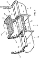
FIG. 1 is a perspective view representing a passenger seating assembly with a bridge table deployed for use according to the present invention; -
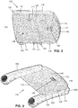
FIG. 2 is a perspective view of the lower side of the bridge table ofFIG. 1 ; -
FIG. 3 is a perspective view of the bridge table as mounted inFIG. 1 in a locked condition, showing only the armrests of the seating assembly; -
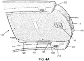
FIG. 4A is a perspective view of the lower side of the bridge table as mounted inFIG. 1 in an unlocked condition, showing only the armrests of the seating assembly; -
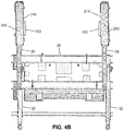
FIG. 4B is a perspective view of the armrests ofFIG. 4A without the bridge table for illustration of both mounting panels; -
FIG. 4C is perspective view of the bridge table ofFIG. 4A without the armrests; -
FIG. 5A is a top plan view of internal components of the bridge table ofFIG. 1 ; -
FIG. 5B is a side view of internal components of the bridge table ofFIG. 1 ; -
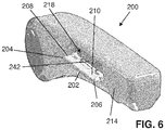
FIG. 6 is a perspective view of an armrest having a mounting panel deployed to support a bridge table; -
FIG. 7 is a perspective view of the mounting panel ofFIG. 6 ; -
FIG. 8 is a perspective view of internal components of the armrest ofFIG. 6 ; -
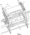
FIG. 9 is a perspective view representing another passenger seating assembly with the bridge table ofFIG. 1 deployed for use according to the present invention; -
FIG. 10 is a perspective view of the passenger left armrest structure ofFIG. 9 , shown with a mounting panel thereof in a stowed condition; -
FIG. 11 is a perspective view of internal components of the armrest structure ofFIG. 10 ; -
FIG. 12 is a perspective view of the mounting panel ofFIGS. 10 and11 ; -
FIG. 13 is a perspective view of a box, according to the present invention, for storing a bridge table; -
FIG. 14 is another perspective view of the box ofFIG. 13 ; and -
FIG. 15 a perspective view of the box ofFIG. 14 , shown without its door to illustrate the interior. - The description set forth below in connection with the appended drawings is intended to be a description of various, illustrative embodiments according to the present invention.. Specific features and functionalities are described in connection with each illustrative embodiment however, it will be apparent to those skilled in the art that the disclosed embodiments may be practiced without each of those specific features and functionalities. The aspects, features and functions described below in connection with one embodiment are intended to be applicable to the other embodiments described below except where expressly stated or where an aspect, feature or function is incompatible with an embodiment.
- A bridge table 100 as illustrated in the drawings and described in the following spans the armrests at the lateral sides of a seating position in a seating. The bridge table 100 is advantageously adapted to mount to both the
pivoting armrests 200 in a standard seating row as first described in the following with reference toFIGS. 1-8 , and thearmrests 300 in single-row or forward-most row seating arrangements as subsequently described with reference toFIGS. 9-12 . Abox 400 for stowing the bridge table is lastly described with reference toFIGS. 13-15 . - Referring to
FIG. 1 , a non-limiting example of a passenger seating assembly is shown generally atreference numeral 20. Theseating assembly 20 is generally supported by a number of vertically standinglegs 22 interconnected by horizontaltransverse beam tubes 26.Spreaders 28 that support pivotingarmrests 200 extend upward from thelegs 22. In an assembled seating assembly, a passenger seat is mounted between each spaced adjacent pair ofspreaders 28. InFIG. 1 , two central sets of legs are shown, and twoarmrests 200 are shown, defining acentral position 30 for a passenger seat between thespreaders 28 and over thebeam tubes 26. Two positions adjacent the central position, particularly aleft position 32 and aright position 34, termed according to the perspective of a seated occupant, are for seats adjacent thecentral position 30. Theseating assembly 20 is shown just for example to have three seating positions. These descriptions relate as well to rows having any number of seating positions. Thus, the bridge table 100 can be mounted on the armrests of any seat in a two seat arrangement, a three seat arrangement, a four seat arrangement, or even on a single seat. - The bridge table 100 mounted on the
armrests 200 inFIG. 1 is deployed for use by occupants of seats that would be arranged in the left position and right position in a fully assembled seating group. The bridge table 100 can be stowed in thestorage box 400 mounted to and below thebeam tubes 26. The bridge table 100 inFIG. 1 is supported at opposing lateral sides by forward disposed and generallyhorizontal armrests 200 pivotally attached torespective spreaders 28. - As shown in
FIG. 1 , theupper side 102 of the bridge table 100 has forwardreceptacles 104, such as cup holders and recesses, for beverages, food items and other small articles such as utensils, phones, writing implements and such. Apad 106 extends across the rearward upper side of the bridge table 100. Thepad 106 may be pliable, patterned, and textured to provide contact friction with items placed on the pad such as laptop computers and plates for serving food. For example, thepad 106 can be padded leather bonded to sheet metal. Other materials and constructions are within the scope of these descriptions. Inserts may be included in the bottoms of theforward receptacles 104 and may match the pad, for example in material or color. Thepad 106, the inserts, and bridge table 100 overall may be colored and aesthetically prepared to be consistent with a themed appearance in an aircraft cabin as desired. -
FIG. 2 shows thelower side 108 of the bridge table 100. Therearward end 110 of bridge table 100 generally faces the back rest of a passenger seat when the bridge table 100 is mounted on armrests for use. Aforward end 112 of the bridge table 100 opposite therearward end 110 generally faces forward, for example toward the back of a forward seating row. The lateral sides 114 of the bridge table 100 engage respective armrests when mounted. Eachlateral side 114 has multiple engagement features for registering and attaching the bridge table 100 relative to an armrest. In particular, first and second spaced tabs, referenced as arearward tab 116 and aforward tab 117, extend downward from thelower side 108 of the bridge table 100 along eachlateral side 114. A rearward fixedhook 120, which opens forward, is positioned rearward of therearward tab 116. Aforward actuating hook 122, which opens rearward, is positioned forward of theforward tab 117. - The bridge table 100 is securely mounted on an
armrest 200 when, as shown inFIG. 3 particularly for the left-side armrest 200, a mountingpanel 202 that deploys from the armrest is engaged by the engagement features at thelateral side 114 of the bridge table 100. In particular, the rearward fixedhook 120 of the bridge table 100 engages therearward end 204 of the mounting panel 202 (see alsoFIG. 6 ). Theforward actuating hook 122 of the bridge table 100 engages theforward end 206 of the mountingpanel 202. Asupport side 210 of the deployed mountingpanel 202 has a first or rearward slot 216 (FIG. 7 ) and second orforward slot 217 that align with and receive therearward tab 116 andforward tab 117 of bridge table 100 respectively. - The
forward actuating hook 122 is movable forward and rearward to unlock and lock the bridge table 100 to the mountingpanel 202. Theactuating hook 122 is shown in the rearward and locked position inFIG. 3 , in which theactuating hook 122 engages theforward end 206 of the mountingpanel 202 preventing removal of the bridge table 100 from the armrest. Theactuating hook 122 is shown in the forward and unlocked position inFIGS. 4A and4C . When the bridge table 100 is placed on the mounting panels 202 (FIG. 4A ) with theactuating hook 122 in the forward and unlocked position, theactuating hook 122 is disengaged from theforward end 206 of the mountingpanel 202 permitting removal of the bridge table 100 from the armrest. The forward actuating hooks 122 are biased toward the locked position. An actuatable handle 130 along thelower side 108 of the bridge table 100 is used by hand to move the actuating hooks 122 to their unlocked positions to permit the bridge table 100 to be removed from the armrests. - For direct illustration of the two mounting panels on which the bridge table is mounted,
FIG. 4B shows a passenger left sidefirst armrest 200 with afirst mounting panel 202 in the deployed position, and a passenger right sidesecond armrest 200 with asecond mounting panel 203 in the deployed position.FIG. 4B represents an airline seating assembly in which thefirst armrest 200 has alateral side 214 to which the first mountingpanel 202 is pivotally attached, and thesecond armrest 200 has alateral side 215 facing the first armrest. Thesecond mounting panel 203 is pivotally attached to thelateral side 215 of thesecond armrest 200. The mountingpanels -
FIG. 5A shows internal components of the bridge table 100 from above.FIG. 5B shows a similar side view, with anexterior wall 118 shown in dashed line for illustration of the interior components. Ayoke 132 is movable in a forward direction against the forces of lateral side springs 134. In the assembled bridge table 100, thehandle 130 is secured to theyoke 132 using fasteners and holes 135 at the forward central junction area of the yoke. Theyoke 132 has symmetrically extendinglateral beams 136 havingends 138 that engage the actuating hooks 122. Eachactuating hook 122 extends downward from a respective fore-aftmovable rail 128 that is biased rearward by aspring 134. The laterally outward end 138 of eachbeam 136 of theyoke 132 engages arespective actuating hook 122 below therail 128 such that theyoke 132 andactuating hook 122 travel together in fore aft movements. Thesprings 134 bias therails 128, and the actuating hooks 122 therewith, rearward to the locked position, thereby also biasing thehandle 130 to a rearward first position (FIG. 3 ). Forward movement of thehandle 130 from the rearward position ofFIG. 3 to a second or forward position ofFIG. 4A pulls theyoke 132 forward, which pulls therails 128 and actuating hooks 122 forward against the forces of thesprings 134. This pulls the actuating hooks 122 forward to their unlocked positions. Release of thehandle 130 permits the actuating hooks 122,yoke 132, and handle 130 to return rearward by the forces applied by thesprings 134. - The bridge table 100 includes indicators, for example embodied as indicator bars comprising indicator surfaces, that show the status, whether in the rearward locked position or the forward unlocked position, of the actuating hooks 122.
FIGS. 2 and 3 show forward edges of the indicator bars 140 as flush with the contouredforward end 112 of the bridge table 100, indicating the positions of the actuating hooks 122 as in the rearward locked positions.FIGS. 4A and4C show the indicator bars 140 as pivoted outward to extended positions from respective receiving areas in theforward end 112 of the bridge table 100, indicating the positions of the actuating hooks 122 as in the forward unlocked positions. Within the bridge table 100 (FIG. 5A ), the pivoting indicator bars 140 are coupled to theyoke 132 byrespective links 142. As theyoke 132 moves forward by user action grasping thehandle 130 for example, the indicator bars 140 are pivoted to their extended positions from theforward end 112 of the bridge table 100. As theyoke 132 is returned rearward by the force of thesprings 134, the indicator bars 140 are pivotally returned to their flush withdrawn positions by the links. Accordingly, the indicator bars 140 indicate the position of theyoke 132, and thereby provide visual confirmation of the locked or unlocked status of the actuating hooks 122. In the illustrated example, the indicator bars 140 haveindicator surfaces 144 that are hidden within the bridge table 100 when in the withdrawn positions and visible for viewing inspection when in the extended positions. The indicator surfaces 144 may be colored brightly or inconsistently with other colors or themes of the bridge table 100 to enhance their visibility when in the extended positions (FIGS. 4A ,4C ). - Once the actuating hooks reach their forward unlocked positions, a keeper latch 123 (
FIG. 5A ) at each lateral side of the bridge table 100 maintains arespective actuating hook 122 forward until the bridge table 100 is mounted upon mountingpanels 202. As shown inFIG. 5B , thekeeper latch 123 includes aforward engagement arm 124 and arearward trigger tab 125. A central part of thekeeper latch 123, between theforward engagement arm 124 andrearward trigger tab 125, is pivotally mounted to the bridge table interior. A biasingspring 126 persistently presses therearward trigger tab 125 downward toward aslot 127 through thelower side 108 of the bridge table. When theactuating hook 122 reaches the forward unlocked position, and bridge table 100 is removed from contact with the mountingpanels 202, the keeper latches 123 automatically pivot, as biased by thesprings 126. This extends thetrigger tabs 125 through the slots as shown inFIG. 4C , and raises theforward engagement arms 124 to engage the rearward ends of therails 138 of the actuating hooks 122, latching the actuating hooks in the forward position. This also presses the yoke 132 (FIG. 5A ) forward and thereby pivots the indicator bars 140 outward to their extended positions (FIGS. 4A ,4C ). When the bridge table 100 is placed upon mountingpanels 202, the mounting panels press thetrigger tabs 125 inward, which automatically pivots the keeper latches 123 to lower theforward engagement arms 124 and disengage therails 138, permitting theyoke 132, actuating hooks 122, and handle 130 to return rearward by the forces applied by thesprings 134. This pivots the indicator bars 140 to their inward positions (FIGS. 2-3 ). Thus, because thekeeper latch 123 automatically maintains theactuating hook 122 in the unlocked condition until thetrigger 125 is pressed by a mountingpanel 202, the keeper latches 123 provide assurance that the correct status of the bridge table 100 (mounted or dismounted) is indicated by the indicator bars 140. -
FIG. 5A also shows a sound deadening pads orlayer 146 within the bridge table 100. The pads orlayer 146 reduce the otherwise sharp sounds of the moving elements of the bridge table and sound made when being engaged with the mounting panels. - The
support side 210 of the deployed mountingpanel 202 has rampedcontacts areas 208 at the rearward end 204 (FIG. 6 ) and forward end 206 (FIG. 7 ) to facilitate engagement as the bridge table 100 approaches from above while being mounted to the armrests. Similarly, theactuating hook 122 has a lower-side ramped contact area 144 (FIG. 4A ) at its rearward end to promote sliding movement and engagement. The above-described engagement features at thelateral side 114 of the bridge table 100, and rampedcontact areas 208 of the mountingpanel 202, permit a wide range of angles for the approach and contact of the bridge table 100 as attachment to thearmrest 200 occurs. When therearward tab 116 andforward tab 117 of the bridge table 100 align with and insert into therearward slot 216 andforward slot 217 of the mountingpanel 202, respectively, the bridge table 100 and mountingpanel 202 engage. Therearward end 204 of the mountingpanel 202 engages and is captured by the rearward fixedhook 120, and theforward actuating hook 122 can travel rearward to engage and capture theforward end 206 of the mountingpanel 202. Theforward actuating hook 122 can travel forward automatically, according for example to the above-described rampedcontact areas 208, as the bridge table 100 is pressed toward the mountingpanels 202 by user action, even without necessitating direct use of thehandle 130. Theforward actuating hook 122 can automatically return rearward, locking the bridge table 100 to the armrests. Thebridge table tabs panel slots handle 130 and pulling it forward. -
FIG. 6 shows the mountingpanel 202 deployed for use and mounting a bridge table 100.FIG. 7 shows the mountingpanel 202 without other armrest structures for illustration purposes.FIG. 8 illustrates actuating internal components of the armrest ofFIG. 6 , including the deployed mountingpanel 202. A left-side mounting panel 202 is particularly shown inFIGS. 6-8 . The mountingpanel 202 is pivotally attached to, and deploys from, thelateral side 214 of thearmrest 200 to engage and support eachlateral side 114 of the bridge table 100. The two armrests that support a mounted bridge table 100 are sufficiently symmetric in their mounting features to permit the descriptions and illustrations (FIGS. 6-7 ) of the attachment of onelateral side 114 of the bridge table 100, in particular the passenger left side, to suffice. The right-side mounting panel 203 (FIG. 4B ) is also thereby described by way of mirror symmetry about a plane between the left and right-side armrests. - The mounting
panel 202 is pivotally attached to the armrest by a generally horizontal fore-aft extending axle 220 (FIG. 8 ) that defines a pivot axis 222 (FIG. 7 ). Torsion springs 224 bias the mountingpanel 202 to pivot laterally outward from thearmrest 200 to the illustrated deployed position in which the mountingpanel 202 is generally horizontal. A first side of the mountingpanel 202 referenced as thesupport side 210 is generally horizontal and facing upward in the deployed position. In a stowed position (not shown), thesupport side 210 is generally vertical, facing into a receivingarea 218 of the armrest where the mountingpanel 202 stows. In the stowed position, asecond side 212 of the mountingpanel 202, opposite thesupport side 210, faces laterally outward from thearmrest 200 generally flush with thelateral side 214 of the armrest. - At the
rearward end 204 of the mountingpanel 202, a rigid arm 226 (FIG. 7 ) extends from the mountingpanel 202 beyond thepivot axis 222 and actuates a lockinglever 230 within the armrest as the mountingpanel 202 reaches the deployed position as shown inFIG. 8 . The lockinglever 230 is pivotally mounted to thearmrest 200 and biased toward thearm 226 and to an unlocked position by a spring 228. The lockinglever 230 is automatically actuated by thearm 226, thereby locking thearmrest 200 in the forward disposed and generally horizontal position and preventing the armrest from pivoting upward, when the mountingpanel 202 reaches the deployed position. As the mountingpanel 202 is returned to the stowed position, thearm 226 releases the lockinglever 230 thereby unlocking thearmrest 200 and permitting it to pivot upward by user action if desired. - The
rigid arm 226 also latches the mountingpanel 202 in the stowed position (not shown) by engaging a pivotinglatch lever 232 within the armrest. The latch lever 232 (FIG. 8 ) has arearward end 234 defining a user-actuatable button in the lower side of the armrest 200 (FIG. 3 ). Aforward end 236 of thelatch lever 232 is marked in dashed lines as hidden by therearward end 204 of the mountingpanel 202 inFIG. 8 . Pressing therearward end 234 of the latch lever upward by user action pivots theforward end 236 downward away from engagement with thearm 226, releasing the mountingpanel 202 to pivot outward to the illustrated deployed position by force of the torsion springs 224. To return the mountingpanel 202 to the stowed position from the deployed position (FIG. 6 ), a user presses the mountingpanel 202 pivotally into the receivingarea 218 until thearm 226 is engaged by theforward end 236 of the latch lever. A biasingspring 238 biases thelatch lever 232 into a latching position, in which theforward end 236 is pivotally raised to engage thearm 226, thereby latching the mountingpanel 202 in the stowed position. Mutually contacting surfaces of thelatch lever 232 andarm 226 can be beveled to facilitate the return of the mountingpanel 202 to the stowed position. - A contact ledge 240 (
FIG. 7 ) extends from the mountingpanel 202 beyond thepivot axis 222 and engages the lower edge of a plate 242 (FIG. 6 ) in thearmrest 200 when the mountingpanel 202 reaches the deployed position. Thecontact ledge 240 stops rotation of thepivoting mounting panel 202 as the panel deploys and assures the proper horizontal position as thecontact ledge 240 contacts theplate 242. The engagement of the contact ledge with the plate prevents the mountingpanel 202 from pivoting below horizontal as it deploys from thearmrest 200 and firmly maintains the horizontal disposition of the deployed mountingpanel 202 to support a bridge table 100. Thecontact ledge 240 faces vertically in the deployed position and horizontally in the stowed position (not shown). In either position, thecontact ledge 240 and the lower edge of theplate 242 are hidden within thearmrest 200. By bearing load, thehidden contact ledge 240 relieves thesecond side 212 of the mountingpanel 202 from needing to contact any portion of the armrest. This preserves the condition of thesecond side 212, which is the aesthetic show surface, by preventing cosmetic damage for example, as might otherwise occur due to contact between painted or otherwise decorative surfaces. - The preceding descriptions refer to an armrest type that pivots forward to a horizontal position for use as shown in
FIG. 1 . Such pivotingarmrests 200 may be useful, for example, in standard passenger row seating in a cabin environment with multiple rows of seating. Accordingly, the described and illustrated armrests and deployable mountingpanel 202 are non-limiting examples to which the bridge table 100 can be mounted. The bridge table 100 as described and illustrated can be mounted on other types of armrests. In airline cabin environments, a typical seating row relies upon a forward row for deployable seat back trays. However, the forward most row of seating in a column of rows does not rely upon another row for such a table. Accordingly, the armrests in a forward most row may serve as stowage housings for deployable trays. In such seating assemblies, a fixed armrest may be designed with notable differences from the pivoting armrests ofFIG. 1 . - For example, referring to
FIG. 9 , a non-limiting example of a passenger seating assembly having fixedarmrests 300 may be advantageous for use in a single-row seating environment or as a forward most row of seating in a column of rows. Only a single seating assembly position is shown, representing any position in a seating row having any number of positions. Thearmrests 300 inFIG. 9 serve as housings for trays 318 (FIG. 10 ) that deploy through openings under pivoting covers. Thetray 318 inFIG. 10 is shown in its stowed vertical position by dashed line for hidden portions within the armrest. The covers, in their closed positions, serve as arm support surfaces for use by seat occupants. A passenger-right cover 314 is shown in the closed position inFIG. 9 , and a passenger-left cover 315 is shown in the open position. The bridge table 100 described above is shown mounted on the fixedarmrests 300. The covers are pivotally connected to their respective armrests by hinges. The covers may be biased into and/or releasably latched in their closed positions. - The two
armrests 300 that support the mounted bridge table 100 are sufficiently symmetric in their mounting features to permit these descriptions and illustrations of the left side structure to suffice. A mountingpanel 302 according to the embodiment illustrated inFIGS. 9-12 is pivotally attached to thearmrest 300 by a generally horizontal fore-aft extending axle 320 (FIG. 11 ) that defines a pivot axis 322 (FIG. 12 ). Torsion springs bias the mountingpanel 302 to pivot laterally outward from the illustrated stowed position flush within a receiving area of thearmrest 300. A first side of the mountingpanel 302 referenced as the support side 310 (FIG. 12 ) is generally horizontal and facing upward in the deployed position. In the stowed position (FIGS. 10-11 ), thesupport side 310 is generally vertical, facing into the receiving area of the armrest. - The bridge table 100 attaches to the mounting
panel 302 ofFIGS. 10-12 in a similar fashion as to the mountingpanel 202 ofFIGS. 3 ,5 and7 . The rearward fixedhook 120 of the bridge table 100 engages therearward end 304 of the mountingpanel 302. Theforward actuating hook 122 of the bridge table 100 engages theforward end 306 of the mountingpanel 302. Therearward tab 116 andforward tab 117 of bridge table 100 align with and insert into therearward slot 316 andforward slot 317 in thesupport side 310 of the mountingpanel 302. By use of the handle 130 (FIG. 3 ) the bridge table 100 can be disengaged from the mountingpanel 302 in the same fashion as it is disengaged from the mountingpanel 202. Like the first-describedmounting panel 202, the mountingpanel 302 ofFIGS. 10-12 has rampedcontact areas 308 at therearward end 304 andforward end 306 of thesupport side 310 to facilitate engagement with the bridge table 100. A contact ledge 340 (FIG. 12 ) extends from the mountingpanel 302 beyond the pivot axis and engages the lower edge of a plate in thearmrest 300 when the mountingpanel 302 reaches the deployed position. Thecontact ledge 340 stops rotation of thepivoting mounting panel 302 as the panel deploys and assures the proper horizontal position as thecontact ledge 340 contacts the plate. The load bearingcontact ledge 340 preserves the condition of thesecond side 312 of the mountingpanel 302, which is the aesthetic show surface, in the same fashion as described in the preceding with reference to the mountingpanel 302. - At the
rearward end 304 of the mountingpanel 302, an end segment 326 (FIG. 12 ) of thecontact ledge 340 serves a latching function similar to therigid arm 226 of the first-describedmounting panel 202. Theledge segment 326 latches the mountingpanel 302 in the stowed position by engaging a pivotinglatch lever 332 within thearmrest 300. The latch lever 332 (FIG. 8 ) has arearward end 334 pivotally connected to an internal frame point of thearm support 300. Aforward end 336 of thelatch lever 332 raises as the latch lever pivots upward to a latching position, and, lowers as the latch lever pivots downward to an unlatching position. In the latching position, theforward end 336 engagesledge segment 336. Thelatch lever 332 is biased into the latching position bylinear springs 338. - Intermediate the rearward end and forward end, a
member 330 extends upward from thelatch lever 332 for use in actuating the latch lever by hand. Pressing the upper end of themember 330 downward by user action pivots theforward end 336 downward away from engagement with theledge segment 340 of the mountingpanel 302, releasing the mountingpanel 302 to pivot outward to the deployed position. To return the mountingpanel 302 to the stowed position (FIG. 10 ), a user presses the mountingpanel 302 pivotally into the receiving area until thelatch lever 332 engages by the mountingpanel 202. The upper end of themember 330 is hidden when thecover 314 is in the closed position, and available for user action when the cover is in the open position. - As shown in
FIGS. 1 and9 , abox 400 can be provided for stowing the bridge table 100. Thebox 400 is shown as mounted to thetransverse beam tubes 26 beneath the seat assembly. The box 400 (FIG. 13 ) has aninner liner 402 for housing the bridge table 100, and an outer structure by which the box is mounted to thebeam tubes 26. The outer structure is referenced as a mountingbracket 404 by which the box is attached to thetransverse beam tubes 26. The mountingbracket 404 has an upper cage portion 406 (FIG. 13 ) and a lower skeletonized strap 410 (FIG. 14 ) that together wrap around and support theinner liner 402. Mountingclips 412 extend upward from the mountingbracket 404 in spaced relation corresponding to thebeam tubes 26 to align with and engage the tubes. Encirclingfasteners 408, shown as tie wraps in the illustrated example, wrap around thetubes 26 andclips 412 thereby securing the mountingbracket 404 to thebeam tubes 26. - The
inner liner 402 is shown as having a rigid upper shell 414 (FIG. 15 ) and a rigidlower shell 416 connected together to define anenclosure interior 420 for receiving the bridge table 100. Adoor 422 is pivotally attached to the mountingbracket 404 by mounting plates extending forward from thestrap 410.Hinges 424 pivotally attach thedoor 422 the mounting plates at the forward end of the lower shell 416 (FIG. 14 ). Spaced latches 426 automatically releasably secure thedoor 422 in the closed position thereof (FIGS. 13-14 ) when the door is pivoted upward from its open position by user action. Thelatches 426 are releasable by user action to permit the door to be pivotally opened. Arespective hood 430 partially covers each latch, particularly from above, to prevent accidental release of the latches as a seat occupant moves personal items and/or adjusts their seat position. - By mounting the
box 400 below the passenger seating assembly, a stowed bridge table 100 is conveniently available close to the point of expected use. Further mounting provisions can be attached to the lower side of the mountingbracket 404 for supporting such articles as life vest containers, pouches, boxes, and other equipment items. Thus, the mountedbox 400 does not interfere with expected functions and features of the seat assembly. The mounted box does not significantly alter the strength or stiffness of the seat assembly. Thebox 400 protects an enclosed bridge table 100 from spills, debris, and damage. Theliner 402, within the interior thereof (FIG. 15 ), provides multi-directional locating features in form of ramps,ribs 434, bumpers, protuberances, or other structures to guide insertion of the bridge table 100 into the enclosure and assure its location in a stowed position. Drainage openings are defined through the lower shell of the liner to permit the escape of any potential liquid intrusion. - The features of the above descriptions and referenced drawings can be combined in whole in part in various ways to provide a bridge table 100 to passenger seating assemblies. The
armrests 200 ofFIGS. 3 and9-10 can be installed with new seating assemblies or can replace or retrofit existing armrests. By relying on almost universal seat frame elements such as thespreaders 28 andbeam tubes 26 for mounting, thearmrests storage box 400 can be added to many cabin environment arrangements. The bridge table 100 as illustrated and described in the preceding can be mounted on thearmrests 200 ofFIGS. 3 and/or thearmrests 300 ofFIGS. 9-10 , which can be selectively installed in standard seating assemblies where columns of standard seating rows are arranged and/or in single row or forward most row seating. - While the foregoing description provides embodiments of the invention by way of example only, it is envisioned that other embodiments that are within the scope of the present invention as defined in the claims may perform similar functions and/or achieve similar results.
Claims (15)
- A seat assembly, comprising:a first armrest (200, 300) having a first lateral side (214) and a first mounting panel (202, 302) pivotally attached to the first lateral side (214), the first mounting panel (202, 302) pivotable between a stowed position and a deployed position;a second armrest (200, 300) having a second lateral side (215) facing the first armrest (200, 300), and a second mounting panel (203, 302) pivotally attached to the second lateral side (215), the second mounting panel (203, 302) pivotable between a stowed position and a deployed position; anda bridge table (100) having a first lateral side (214) for mounting upon the first mounting panel (202, 302), and a second lateral side (215) for mounting upon the second mounting panel (203, 302), each lateral side (214, 215) comprising a respective engagement feature for releasably engaging a respective one of the first and second mounting panels (202, 203, 302).
- The seat assembly according to claim 1, wherein the stowed position of the first and/or second mounting panel (202, 203, 302) is a vertical position and/or wherein the deployed position of the first and/or second mounting panel (202, 203, 302) is a horizontal position.
- The seat assembly according to claim 1 or 2, wherein the first and second mounting panels (202, 203, 302) are biased to the horizontal deployed positions by torsio n springs (224), and wherein the first and second armrests (200, 300) comprise respective latch levers (232, 332) for releasing the first and second mounting panels (202, 203, 302) to pivot outward from the lateral sides (214, 215) of the armrests (200, 300) to the horizontal deployed positions.
- The seat assembly according to claim 3, wherein the latch levers (232, 332) are biased to respective latching positions thereby latching the first and second mounting panels (202, 203, 302) in the vertical stowed positions.
- The seat assembly according one or more of the preceding claims, wherein the engagement feature of each lateral side (114) of the bridge table (100) comprises a fixed hook (120) and an actuating hook (122).
- The seat assembly according to claim 5, wherein the fixed hook (120) and actuating hook (122) engage respective opposing ends of the respective first and second mounting panels (202, 203, 302).
- The seat assembly according to claim 5 or 6, wherein the bridge table (100) comprises a handle (130) operative, against the force of a spring, for example, to move each actuating hook (122) from a locked position to an unlocked position to permit the bridge table (100) to be removed from the first and second mounting panels (202, 203, 302).
- The seat assembly according to one or more of claims 5-7, wherein the bridge table (100) comprises at least one indicator indicating a locked or unlocked condition of the actuating hook (122), the bridge table preferably further comprising a keeper latch (123) that automatically maintains the actuating hook (122) in the unlocked condition until a trigger (125) of the keeper latch (123) is pressed by the respective one of the first and second mounting panels (202, 203, 302)., thereby assuring the indicator indicates the locked or unlocked condition correctly.
- The seat assembly according one or more of the preceding claims, wherein the engagement feature of each lateral side (114) of the bridge table (100) comprises spaced tabs (116, 117) received in slots (216, 217) of the respective mounting panel when the bridge table (100) is mounted upon the first and second mounting panels (202, 203, 302).
- The seat assembly according one or more of the preceding claims, wherein each of the first and second mounting panel (202, 203, 302). comprises a contact ledge (240) that stops the respective mounting panel (202, 203, 302) at the horizontal deployed position when the respective mounting panel (202, 203, 302) is pivoted from the vertical stowed position to the horizontal deployed position.
- The seat assembly according one or more of the preceding claims, wherein the contact ledge (240) is hidden within the respective armrest (200, 300).
- The seat assembly according one or more of the preceding claims, wherein the first and second armrests (200, 300) are pivotable, each comprising a respective locking lever (230) automatically actuated when the respective mounting panel (202, 203) reaches the horizontal deployed position, thereby locking the respective armrest (200, 300) in a generally horizontal position.
- The seat assembly according one or more of the preceding claims, further comprising a box (400) for storing the bridge table (100) therein, the box (400) attachable below a seating position of the seat assembly.
- The seat assembly according to claim 13, wherein the box (400) comprises at least one of:a hinging door (422) and actuatable levers operative to permit opening of the door (422);a liner (402) and mounting bracket (404) having a cage portion (406) at least partially surrounding the liner (402); andfasteners (408) extending upwardly from the box (400) in spaced relation corresponding to transverse beam tubes (26) of the seat assembly.
- A seat assembly according one or more of the preceding claims, wherein the bridge table (100) is removably positionable between the first and second armrests (200, 300).
Applications Claiming Priority (1)
| Application Number | Priority Date | Filing Date | Title |
|---|---|---|---|
| US16/436,069 US10946967B2 (en) | 2019-06-10 | 2019-06-10 | Aircraft seat deployable bridge table, mounting provisions, and storage provisions |
Publications (3)
| Publication Number | Publication Date |
|---|---|
| EP3750806A1 true EP3750806A1 (en) | 2020-12-16 |
| EP3750806A8 EP3750806A8 (en) | 2021-03-03 |
| EP3750806B1 EP3750806B1 (en) | 2024-02-14 |
Family
ID=68886775
Family Applications (1)
| Application Number | Title | Priority Date | Filing Date |
|---|---|---|---|
| EP19215166.0A Active EP3750806B1 (en) | 2019-06-10 | 2019-12-11 | Aircraft seat deployable bridge table, mounting provisions, and storage provisions |
Country Status (4)
| Country | Link |
|---|---|
| US (1) | US10946967B2 (en) |
| EP (1) | EP3750806B1 (en) |
| CN (1) | CN112061401B (en) |
| CA (1) | CA3062911A1 (en) |
Cited By (2)
| Publication number | Priority date | Publication date | Assignee | Title |
|---|---|---|---|---|
| RU2827800C1 (en) * | 2023-11-01 | 2024-10-02 | Общество с ограниченной ответственностью "Авиационные интерьеры" | Vehicle seat life jacket storage compartment |
| EP4711274A1 (en) * | 2024-09-13 | 2026-03-18 | B/E Aerospace, Inc. | Seat armrest locking mechanism |
Families Citing this family (2)
| Publication number | Priority date | Publication date | Assignee | Title |
|---|---|---|---|---|
| US11845558B2 (en) * | 2021-08-19 | 2023-12-19 | Recaro Aircraft Seating Gmbh & Co. Kg | Aircraft passenger seat device with a connection unit comprising an impact safety device |
| US12595061B2 (en) * | 2024-05-14 | 2026-04-07 | B/E Aerospace, Inc. | Modular power box mounting system |
Citations (6)
| Publication number | Priority date | Publication date | Assignee | Title |
|---|---|---|---|---|
| US3606449A (en) * | 1969-01-08 | 1971-09-20 | Fairchild Hiller Corp | Tray holder for seats |
| EP0385861A1 (en) * | 1989-03-01 | 1990-09-05 | Societe Industrielle Et Commerciale De Materiel Aeronautique (Sicma) Societe Anonyme | Adjustable passenger seat with a retractable table |
| US5037157A (en) * | 1987-03-28 | 1991-08-06 | Flight Equipment & Engineering Ltd. | Armrest arrangements for vehicle seating |
| US5193765A (en) * | 1989-04-06 | 1993-03-16 | Magerik Ltd. | Seating |
| EP2203328A1 (en) * | 2007-09-25 | 2010-07-07 | Siemens Aktiengesellschaft | Vehicle seat with a table structure which can be assembled for use |
| US20150130249A1 (en) * | 2013-11-08 | 2015-05-14 | Recaro Aircraft Seating Gmbh & Co. Kg. | Aircraft passenger seat device |
Family Cites Families (35)
| Publication number | Priority date | Publication date | Assignee | Title |
|---|---|---|---|---|
| US1134720A (en) * | 1914-05-28 | 1915-04-06 | John H Bradley | Therapeutical device. |
| US2797973A (en) | 1955-02-23 | 1957-07-02 | Anthony S Barbera | Chair tray having pivoted, spring biased, arm-engaging clamps |
| US3893729A (en) | 1974-11-18 | 1975-07-08 | Mc Donnell Douglas Corp | Convertible passenger seat |
| US4113218A (en) * | 1976-09-13 | 1978-09-12 | Linder Gerald S | Adjustable frame assembly for supporting a surgical tray |
| US4533175A (en) * | 1983-12-23 | 1985-08-06 | Ptc Aerospace Inc. | Convertible seat |
| US4576351A (en) * | 1984-06-15 | 1986-03-18 | Brink T A | Portable stroke victims arm rest |
| US4591206A (en) * | 1984-09-04 | 1986-05-27 | Pribble Elvern G | Table attachment for chairs |
| US4668010A (en) * | 1985-02-26 | 1987-05-26 | Ikeda Bussan Co., Ltd. | Seat with armrests adapted to support tray |
| US5074617A (en) * | 1988-05-03 | 1991-12-24 | Len Maxwell | Storage compartment for wheelchair |
| US5207477A (en) * | 1988-05-03 | 1993-05-04 | Len Maxwell | Storage compartment for wheelchair |
| US5582464A (en) * | 1995-01-17 | 1996-12-10 | Maymon; Herzel | Chair primarily for use by persons with spinal chord injury |
| DE19724302A1 (en) | 1997-06-09 | 1998-12-10 | Ster N V De | tray |
| US6062640A (en) | 1998-01-09 | 2000-05-16 | Shilo Technologies, Inc. | Tray attachment for chairs |
| US6298507B1 (en) * | 2000-02-28 | 2001-10-09 | Terry A. Clyburn | Hip grip table attachment for operating tables |
| US7360829B2 (en) * | 2003-12-01 | 2008-04-22 | Bufkin William J | Chair-mountable table |
| DE102004008877A1 (en) * | 2004-02-18 | 2005-09-08 | Recaro Aircraft Seating Gmbh & Co. Kg | Airplane passenger seat row |
| DE102005042377A1 (en) * | 2005-09-07 | 2007-03-08 | Recaro Aircraft Seating Gmbh & Co. Kg | Seating system for passenger vehicles, in particular for aircraft |
| US7500689B2 (en) * | 2005-11-09 | 2009-03-10 | Peter Pasternak | Wheelchair attachments |
| US20070120398A1 (en) * | 2005-11-29 | 2007-05-31 | John Butler | Using Wheelchair Side Guards to form a usable tray |
| DE102005061496A1 (en) * | 2005-12-22 | 2007-07-05 | Recaro Aircraft Seating Gmbh & Co. Kg | Locking device for a table system in a seat, in particular passenger seat |
| US7966952B2 (en) * | 2007-10-24 | 2011-06-28 | Embraer—Empresa Brasileira de Aeronáutica S.A. | Foldable table for aircraft interiors |
| KR100962116B1 (en) * | 2008-01-18 | 2010-06-11 | 고우영 | Chair board |
| JP2013530740A (en) * | 2010-05-28 | 2013-08-01 | ライドアップ モビリティ インコーポレイテッド | Mobility support equipment |
| US8820548B2 (en) | 2011-02-23 | 2014-09-02 | Bambinos!, Llc | Tray device |
| US8528978B2 (en) * | 2011-11-02 | 2013-09-10 | The Boeing Company | Transport vehicle seat back with integrated upright sleep support system |
| US9140044B2 (en) * | 2013-06-07 | 2015-09-22 | GM Global Technology Operations LLC | Dual-opening armrest assembly and vehicle having same |
| SG2013052030A (en) * | 2013-07-04 | 2015-02-27 | Singapore Tech Aerospace Ltd | A seatback for a passenger seat |
| US9756946B2 (en) | 2013-09-21 | 2017-09-12 | Arthur Chang | Portable armrest divider |
| CN103569362B (en) * | 2013-11-21 | 2016-11-23 | 山东太古飞机工程有限公司 | Table for aircraft passenger compartment |
| JP6320157B2 (en) * | 2014-05-02 | 2018-05-09 | 株式会社岡村製作所 | Chair with table |
| AT516954B1 (en) * | 2015-04-15 | 2016-10-15 | Facc Ag | Folding table, especially for an airplane |
| EP3399917B8 (en) * | 2016-01-08 | 2021-12-08 | Medtec Llc | Arm positioning device for supporting the arms of a patient in an arms-up position for therapeutic or diagnostic purposes |
| CN109414112B (en) * | 2016-04-04 | 2021-10-19 | B/E航空公司 | Tray table that can be unfolded from the lower seat back area |
| JP6721441B2 (en) * | 2016-07-14 | 2020-07-15 | 株式会社ニフコ | Table unit |
| JP2018199381A (en) * | 2017-05-26 | 2018-12-20 | トヨタ紡織株式会社 | Table device of vehicle seat |
-
2019
- 2019-06-10 US US16/436,069 patent/US10946967B2/en active Active
- 2019-11-27 CA CA3062911A patent/CA3062911A1/en active Pending
- 2019-12-05 CN CN201911235167.5A patent/CN112061401B/en active Active
- 2019-12-11 EP EP19215166.0A patent/EP3750806B1/en active Active
Patent Citations (6)
| Publication number | Priority date | Publication date | Assignee | Title |
|---|---|---|---|---|
| US3606449A (en) * | 1969-01-08 | 1971-09-20 | Fairchild Hiller Corp | Tray holder for seats |
| US5037157A (en) * | 1987-03-28 | 1991-08-06 | Flight Equipment & Engineering Ltd. | Armrest arrangements for vehicle seating |
| EP0385861A1 (en) * | 1989-03-01 | 1990-09-05 | Societe Industrielle Et Commerciale De Materiel Aeronautique (Sicma) Societe Anonyme | Adjustable passenger seat with a retractable table |
| US5193765A (en) * | 1989-04-06 | 1993-03-16 | Magerik Ltd. | Seating |
| EP2203328A1 (en) * | 2007-09-25 | 2010-07-07 | Siemens Aktiengesellschaft | Vehicle seat with a table structure which can be assembled for use |
| US20150130249A1 (en) * | 2013-11-08 | 2015-05-14 | Recaro Aircraft Seating Gmbh & Co. Kg. | Aircraft passenger seat device |
Cited By (2)
| Publication number | Priority date | Publication date | Assignee | Title |
|---|---|---|---|---|
| RU2827800C1 (en) * | 2023-11-01 | 2024-10-02 | Общество с ограниченной ответственностью "Авиационные интерьеры" | Vehicle seat life jacket storage compartment |
| EP4711274A1 (en) * | 2024-09-13 | 2026-03-18 | B/E Aerospace, Inc. | Seat armrest locking mechanism |
Also Published As
| Publication number | Publication date |
|---|---|
| CA3062911A1 (en) | 2020-12-10 |
| US20200385123A1 (en) | 2020-12-10 |
| CN112061401A (en) | 2020-12-11 |
| US10946967B2 (en) | 2021-03-16 |
| CN112061401B (en) | 2024-05-07 |
| EP3750806B1 (en) | 2024-02-14 |
| EP3750806A8 (en) | 2021-03-03 |
Similar Documents
| Publication | Publication Date | Title |
|---|---|---|
| US6116674A (en) | Removable console for use with a vehicle | |
| EP3750806B1 (en) | Aircraft seat deployable bridge table, mounting provisions, and storage provisions | |
| EP2528473B1 (en) | Seat back assembly | |
| US6135529A (en) | Multi-position sliding center console | |
| US6435587B1 (en) | Console | |
| US7978466B2 (en) | Computer docking station for a vehicle | |
| US7090274B1 (en) | Vehicle storage structure | |
| US9302628B2 (en) | Dual access vehicle storage assembly | |
| US7810862B2 (en) | Dual access vehicle storage assembly | |
| US10086766B2 (en) | Structural composite seat cushion frame and storage lid with lockable latch system | |
| US20060061121A1 (en) | Independent divan door and drawer assembly | |
| EP3703980B1 (en) | Vehicle interior component | |
| US10137841B1 (en) | Automotive vehicle with expandable underseat storage compartment | |
| EP3782909A1 (en) | End bay assembly with deployable step and deployable step constructions | |
| JP2005193883A (en) | Sheet device | |
| US20180001792A1 (en) | Release latch incorporated into a rear wall of a vehicle such as a truck cab | |
| US20070114819A1 (en) | Folding seat assembly | |
| EP4263351B1 (en) | Aircraft seat design with mountable food tray | |
| US10428564B1 (en) | Storage container with latch for seating assembly | |
| CN111071452A (en) | Armrest assembly with in-arm cup holder | |
| US20190308533A1 (en) | Storage for seating assembly | |
| EP3757008B1 (en) | Braking table system for an aircraft | |
| US20230110736A1 (en) | Aircraft storage retainer | |
| US20250223043A1 (en) | Seat headrest | |
| EP0463733B1 (en) | Compartment covers for vehicles |
Legal Events
| Date | Code | Title | Description |
|---|---|---|---|
| PUAI | Public reference made under article 153(3) epc to a published international application that has entered the european phase |
Free format text: ORIGINAL CODE: 0009012 |
|
| STAA | Information on the status of an ep patent application or granted ep patent |
Free format text: STATUS: THE APPLICATION HAS BEEN PUBLISHED |
|
| AK | Designated contracting states |
Kind code of ref document: A1 Designated state(s): AL AT BE BG CH CY CZ DE DK EE ES FI FR GB GR HR HU IE IS IT LI LT LU LV MC MK MT NL NO PL PT RO RS SE SI SK SM TR |
|
| AX | Request for extension of the european patent |
Extension state: BA ME |
|
| RAP1 | Party data changed (applicant data changed or rights of an application transferred) |
Owner name: B/E AEROSPACE, INC. |
|
| STAA | Information on the status of an ep patent application or granted ep patent |
Free format text: STATUS: REQUEST FOR EXAMINATION WAS MADE |
|
| 17P | Request for examination filed |
Effective date: 20210615 |
|
| RBV | Designated contracting states (corrected) |
Designated state(s): AL AT BE BG CH CY CZ DE DK EE ES FI FR GB GR HR HU IE IS IT LI LT LU LV MC MK MT NL NO PL PT RO RS SE SI SK SM TR |
|
| STAA | Information on the status of an ep patent application or granted ep patent |
Free format text: STATUS: EXAMINATION IS IN PROGRESS |
|
| 17Q | First examination report despatched |
Effective date: 20220525 |
|
| P01 | Opt-out of the competence of the unified patent court (upc) registered |
Effective date: 20230608 |
|
| GRAP | Despatch of communication of intention to grant a patent |
Free format text: ORIGINAL CODE: EPIDOSNIGR1 |
|
| STAA | Information on the status of an ep patent application or granted ep patent |
Free format text: STATUS: GRANT OF PATENT IS INTENDED |
|
| INTG | Intention to grant announced |
Effective date: 20230922 |
|
| GRAS | Grant fee paid |
Free format text: ORIGINAL CODE: EPIDOSNIGR3 |
|
| GRAA | (expected) grant |
Free format text: ORIGINAL CODE: 0009210 |
|
| STAA | Information on the status of an ep patent application or granted ep patent |
Free format text: STATUS: THE PATENT HAS BEEN GRANTED |
|
| AK | Designated contracting states |
Kind code of ref document: B1 Designated state(s): AL AT BE BG CH CY CZ DE DK EE ES FI FR GB GR HR HU IE IS IT LI LT LU LV MC MK MT NL NO PL PT RO RS SE SI SK SM TR |
|
| REG | Reference to a national code |
Ref country code: GB Ref legal event code: FG4D |
|
| REG | Reference to a national code |
Ref country code: CH Ref legal event code: EP |
|
| REG | Reference to a national code |
Ref country code: DE Ref legal event code: R096 Ref document number: 602019046435 Country of ref document: DE |
|
| REG | Reference to a national code |
Ref country code: IE Ref legal event code: FG4D |
|
| REG | Reference to a national code |
Ref country code: LT Ref legal event code: MG9D |
|
| REG | Reference to a national code |
Ref country code: NL Ref legal event code: MP Effective date: 20240214 |
|
| PG25 | Lapsed in a contracting state [announced via postgrant information from national office to epo] |
Ref country code: IS Free format text: LAPSE BECAUSE OF FAILURE TO SUBMIT A TRANSLATION OF THE DESCRIPTION OR TO PAY THE FEE WITHIN THE PRESCRIBED TIME-LIMIT Effective date: 20240614 |
|
| PG25 | Lapsed in a contracting state [announced via postgrant information from national office to epo] |
Ref country code: LT Free format text: LAPSE BECAUSE OF FAILURE TO SUBMIT A TRANSLATION OF THE DESCRIPTION OR TO PAY THE FEE WITHIN THE PRESCRIBED TIME-LIMIT Effective date: 20240214 |
|
| PG25 | Lapsed in a contracting state [announced via postgrant information from national office to epo] |
Ref country code: GR Free format text: LAPSE BECAUSE OF FAILURE TO SUBMIT A TRANSLATION OF THE DESCRIPTION OR TO PAY THE FEE WITHIN THE PRESCRIBED TIME-LIMIT Effective date: 20240515 |
|
| REG | Reference to a national code |
Ref country code: AT Ref legal event code: MK05 Ref document number: 1656862 Country of ref document: AT Kind code of ref document: T Effective date: 20240214 |
|
| PG25 | Lapsed in a contracting state [announced via postgrant information from national office to epo] |
Ref country code: HR Free format text: LAPSE BECAUSE OF FAILURE TO SUBMIT A TRANSLATION OF THE DESCRIPTION OR TO PAY THE FEE WITHIN THE PRESCRIBED TIME-LIMIT Effective date: 20240214 Ref country code: NL Free format text: LAPSE BECAUSE OF FAILURE TO SUBMIT A TRANSLATION OF THE DESCRIPTION OR TO PAY THE FEE WITHIN THE PRESCRIBED TIME-LIMIT Effective date: 20240214 Ref country code: RS Free format text: LAPSE BECAUSE OF FAILURE TO SUBMIT A TRANSLATION OF THE DESCRIPTION OR TO PAY THE FEE WITHIN THE PRESCRIBED TIME-LIMIT Effective date: 20240514 |
|
| PG25 | Lapsed in a contracting state [announced via postgrant information from national office to epo] |
Ref country code: ES Free format text: LAPSE BECAUSE OF FAILURE TO SUBMIT A TRANSLATION OF THE DESCRIPTION OR TO PAY THE FEE WITHIN THE PRESCRIBED TIME-LIMIT Effective date: 20240214 |
|
| PG25 | Lapsed in a contracting state [announced via postgrant information from national office to epo] |
Ref country code: AT Free format text: LAPSE BECAUSE OF FAILURE TO SUBMIT A TRANSLATION OF THE DESCRIPTION OR TO PAY THE FEE WITHIN THE PRESCRIBED TIME-LIMIT Effective date: 20240214 |
|
| PG25 | Lapsed in a contracting state [announced via postgrant information from national office to epo] |
Ref country code: RS Free format text: LAPSE BECAUSE OF FAILURE TO SUBMIT A TRANSLATION OF THE DESCRIPTION OR TO PAY THE FEE WITHIN THE PRESCRIBED TIME-LIMIT Effective date: 20240514 Ref country code: NO Free format text: LAPSE BECAUSE OF FAILURE TO SUBMIT A TRANSLATION OF THE DESCRIPTION OR TO PAY THE FEE WITHIN THE PRESCRIBED TIME-LIMIT Effective date: 20240514 Ref country code: NL Free format text: LAPSE BECAUSE OF FAILURE TO SUBMIT A TRANSLATION OF THE DESCRIPTION OR TO PAY THE FEE WITHIN THE PRESCRIBED TIME-LIMIT Effective date: 20240214 Ref country code: LT Free format text: LAPSE BECAUSE OF FAILURE TO SUBMIT A TRANSLATION OF THE DESCRIPTION OR TO PAY THE FEE WITHIN THE PRESCRIBED TIME-LIMIT Effective date: 20240214 Ref country code: IS Free format text: LAPSE BECAUSE OF FAILURE TO SUBMIT A TRANSLATION OF THE DESCRIPTION OR TO PAY THE FEE WITHIN THE PRESCRIBED TIME-LIMIT Effective date: 20240614 Ref country code: HR Free format text: LAPSE BECAUSE OF FAILURE TO SUBMIT A TRANSLATION OF THE DESCRIPTION OR TO PAY THE FEE WITHIN THE PRESCRIBED TIME-LIMIT Effective date: 20240214 Ref country code: GR Free format text: LAPSE BECAUSE OF FAILURE TO SUBMIT A TRANSLATION OF THE DESCRIPTION OR TO PAY THE FEE WITHIN THE PRESCRIBED TIME-LIMIT Effective date: 20240515 Ref country code: FI Free format text: LAPSE BECAUSE OF FAILURE TO SUBMIT A TRANSLATION OF THE DESCRIPTION OR TO PAY THE FEE WITHIN THE PRESCRIBED TIME-LIMIT Effective date: 20240214 Ref country code: ES Free format text: LAPSE BECAUSE OF FAILURE TO SUBMIT A TRANSLATION OF THE DESCRIPTION OR TO PAY THE FEE WITHIN THE PRESCRIBED TIME-LIMIT Effective date: 20240214 Ref country code: BG Free format text: LAPSE BECAUSE OF FAILURE TO SUBMIT A TRANSLATION OF THE DESCRIPTION OR TO PAY THE FEE WITHIN THE PRESCRIBED TIME-LIMIT Effective date: 20240214 Ref country code: AT Free format text: LAPSE BECAUSE OF FAILURE TO SUBMIT A TRANSLATION OF THE DESCRIPTION OR TO PAY THE FEE WITHIN THE PRESCRIBED TIME-LIMIT Effective date: 20240214 |
|
| PG25 | Lapsed in a contracting state [announced via postgrant information from national office to epo] |
Ref country code: PT Free format text: LAPSE BECAUSE OF FAILURE TO SUBMIT A TRANSLATION OF THE DESCRIPTION OR TO PAY THE FEE WITHIN THE PRESCRIBED TIME-LIMIT Effective date: 20240614 Ref country code: PL Free format text: LAPSE BECAUSE OF FAILURE TO SUBMIT A TRANSLATION OF THE DESCRIPTION OR TO PAY THE FEE WITHIN THE PRESCRIBED TIME-LIMIT Effective date: 20240214 |
|
| PG25 | Lapsed in a contracting state [announced via postgrant information from national office to epo] |
Ref country code: SE Free format text: LAPSE BECAUSE OF FAILURE TO SUBMIT A TRANSLATION OF THE DESCRIPTION OR TO PAY THE FEE WITHIN THE PRESCRIBED TIME-LIMIT Effective date: 20240214 Ref country code: PT Free format text: LAPSE BECAUSE OF FAILURE TO SUBMIT A TRANSLATION OF THE DESCRIPTION OR TO PAY THE FEE WITHIN THE PRESCRIBED TIME-LIMIT Effective date: 20240614 Ref country code: PL Free format text: LAPSE BECAUSE OF FAILURE TO SUBMIT A TRANSLATION OF THE DESCRIPTION OR TO PAY THE FEE WITHIN THE PRESCRIBED TIME-LIMIT Effective date: 20240214 Ref country code: LV Free format text: LAPSE BECAUSE OF FAILURE TO SUBMIT A TRANSLATION OF THE DESCRIPTION OR TO PAY THE FEE WITHIN THE PRESCRIBED TIME-LIMIT Effective date: 20240214 |
|
| PG25 | Lapsed in a contracting state [announced via postgrant information from national office to epo] |
Ref country code: DK Free format text: LAPSE BECAUSE OF FAILURE TO SUBMIT A TRANSLATION OF THE DESCRIPTION OR TO PAY THE FEE WITHIN THE PRESCRIBED TIME-LIMIT Effective date: 20240214 |
|
| PG25 | Lapsed in a contracting state [announced via postgrant information from national office to epo] |
Ref country code: SM Free format text: LAPSE BECAUSE OF FAILURE TO SUBMIT A TRANSLATION OF THE DESCRIPTION OR TO PAY THE FEE WITHIN THE PRESCRIBED TIME-LIMIT Effective date: 20240214 |
|
| PG25 | Lapsed in a contracting state [announced via postgrant information from national office to epo] |
Ref country code: CZ Free format text: LAPSE BECAUSE OF FAILURE TO SUBMIT A TRANSLATION OF THE DESCRIPTION OR TO PAY THE FEE WITHIN THE PRESCRIBED TIME-LIMIT Effective date: 20240214 Ref country code: EE Free format text: LAPSE BECAUSE OF FAILURE TO SUBMIT A TRANSLATION OF THE DESCRIPTION OR TO PAY THE FEE WITHIN THE PRESCRIBED TIME-LIMIT Effective date: 20240214 |
|
| PG25 | Lapsed in a contracting state [announced via postgrant information from national office to epo] |
Ref country code: SK Free format text: LAPSE BECAUSE OF FAILURE TO SUBMIT A TRANSLATION OF THE DESCRIPTION OR TO PAY THE FEE WITHIN THE PRESCRIBED TIME-LIMIT Effective date: 20240214 |
|
| PG25 | Lapsed in a contracting state [announced via postgrant information from national office to epo] |
Ref country code: SM Free format text: LAPSE BECAUSE OF FAILURE TO SUBMIT A TRANSLATION OF THE DESCRIPTION OR TO PAY THE FEE WITHIN THE PRESCRIBED TIME-LIMIT Effective date: 20240214 Ref country code: SK Free format text: LAPSE BECAUSE OF FAILURE TO SUBMIT A TRANSLATION OF THE DESCRIPTION OR TO PAY THE FEE WITHIN THE PRESCRIBED TIME-LIMIT Effective date: 20240214 Ref country code: RO Free format text: LAPSE BECAUSE OF FAILURE TO SUBMIT A TRANSLATION OF THE DESCRIPTION OR TO PAY THE FEE WITHIN THE PRESCRIBED TIME-LIMIT Effective date: 20240214 Ref country code: EE Free format text: LAPSE BECAUSE OF FAILURE TO SUBMIT A TRANSLATION OF THE DESCRIPTION OR TO PAY THE FEE WITHIN THE PRESCRIBED TIME-LIMIT Effective date: 20240214 Ref country code: DK Free format text: LAPSE BECAUSE OF FAILURE TO SUBMIT A TRANSLATION OF THE DESCRIPTION OR TO PAY THE FEE WITHIN THE PRESCRIBED TIME-LIMIT Effective date: 20240214 Ref country code: CZ Free format text: LAPSE BECAUSE OF FAILURE TO SUBMIT A TRANSLATION OF THE DESCRIPTION OR TO PAY THE FEE WITHIN THE PRESCRIBED TIME-LIMIT Effective date: 20240214 |
|
| REG | Reference to a national code |
Ref country code: DE Ref legal event code: R097 Ref document number: 602019046435 Country of ref document: DE |
|
| PG25 | Lapsed in a contracting state [announced via postgrant information from national office to epo] |
Ref country code: IT Free format text: LAPSE BECAUSE OF FAILURE TO SUBMIT A TRANSLATION OF THE DESCRIPTION OR TO PAY THE FEE WITHIN THE PRESCRIBED TIME-LIMIT Effective date: 20240214 |
|
| PLBE | No opposition filed within time limit |
Free format text: ORIGINAL CODE: 0009261 |
|
| STAA | Information on the status of an ep patent application or granted ep patent |
Free format text: STATUS: NO OPPOSITION FILED WITHIN TIME LIMIT |
|
| PG25 | Lapsed in a contracting state [announced via postgrant information from national office to epo] |
Ref country code: IT Free format text: LAPSE BECAUSE OF FAILURE TO SUBMIT A TRANSLATION OF THE DESCRIPTION OR TO PAY THE FEE WITHIN THE PRESCRIBED TIME-LIMIT Effective date: 20240214 |
|
| 26N | No opposition filed |
Effective date: 20241115 |
|
| PG25 | Lapsed in a contracting state [announced via postgrant information from national office to epo] |
Ref country code: SI Free format text: LAPSE BECAUSE OF FAILURE TO SUBMIT A TRANSLATION OF THE DESCRIPTION OR TO PAY THE FEE WITHIN THE PRESCRIBED TIME-LIMIT Effective date: 20240214 |
|
| PG25 | Lapsed in a contracting state [announced via postgrant information from national office to epo] |
Ref country code: MC Free format text: LAPSE BECAUSE OF FAILURE TO SUBMIT A TRANSLATION OF THE DESCRIPTION OR TO PAY THE FEE WITHIN THE PRESCRIBED TIME-LIMIT Effective date: 20240214 |
|
| REG | Reference to a national code |
Ref country code: CH Ref legal event code: PL |
|
| PG25 | Lapsed in a contracting state [announced via postgrant information from national office to epo] |
Ref country code: LU Free format text: LAPSE BECAUSE OF NON-PAYMENT OF DUE FEES Effective date: 20241211 |
|
| REG | Reference to a national code |
Ref country code: BE Ref legal event code: MM Effective date: 20241231 |
|
| PG25 | Lapsed in a contracting state [announced via postgrant information from national office to epo] |
Ref country code: BE Free format text: LAPSE BECAUSE OF NON-PAYMENT OF DUE FEES Effective date: 20241231 |
|
| PG25 | Lapsed in a contracting state [announced via postgrant information from national office to epo] |
Ref country code: CH Free format text: LAPSE BECAUSE OF NON-PAYMENT OF DUE FEES Effective date: 20241231 |
|
| PG25 | Lapsed in a contracting state [announced via postgrant information from national office to epo] |
Ref country code: IE Free format text: LAPSE BECAUSE OF NON-PAYMENT OF DUE FEES Effective date: 20241211 |
|
| PGFP | Annual fee paid to national office [announced via postgrant information from national office to epo] |
Ref country code: DE Payment date: 20251126 Year of fee payment: 7 |
|
| PGFP | Annual fee paid to national office [announced via postgrant information from national office to epo] |
Ref country code: GB Payment date: 20251120 Year of fee payment: 7 |
|
| PGFP | Annual fee paid to national office [announced via postgrant information from national office to epo] |
Ref country code: FR Payment date: 20251120 Year of fee payment: 7 |