EP3750725B1 - Transport refrigeration system and method of operating it - Google Patents
Transport refrigeration system and method of operating it Download PDFInfo
- Publication number
- EP3750725B1 EP3750725B1 EP19305759.3A EP19305759A EP3750725B1 EP 3750725 B1 EP3750725 B1 EP 3750725B1 EP 19305759 A EP19305759 A EP 19305759A EP 3750725 B1 EP3750725 B1 EP 3750725B1
- Authority
- EP
- European Patent Office
- Prior art keywords
- variable
- storage device
- energy storage
- invertor
- refrigeration unit
- Prior art date
- Legal status (The legal status is an assumption and is not a legal conclusion. Google has not performed a legal analysis and makes no representation as to the accuracy of the status listed.)
- Revoked
Links
Images

Classifications
-
- B—PERFORMING OPERATIONS; TRANSPORTING
- B60—VEHICLES IN GENERAL
- B60H—ARRANGEMENTS OF HEATING, COOLING, VENTILATING OR OTHER AIR-TREATING DEVICES SPECIALLY ADAPTED FOR PASSENGER OR GOODS SPACES OF VEHICLES
- B60H1/00—Heating, cooling or ventilating devices
- B60H1/32—Cooling devices
- B60H1/3204—Cooling devices using compression
- B60H1/3205—Control means therefor
- B60H1/3211—Control means therefor for increasing the efficiency of a vehicle refrigeration cycle
-
- F—MECHANICAL ENGINEERING; LIGHTING; HEATING; WEAPONS; BLASTING
- F25—REFRIGERATION OR COOLING; COMBINED HEATING AND REFRIGERATION SYSTEMS; HEAT PUMP SYSTEMS; MANUFACTURE OR STORAGE OF ICE; LIQUEFACTION SOLIDIFICATION OF GASES
- F25D—REFRIGERATORS; COLD ROOMS; ICE-BOXES; COOLING OR FREEZING APPARATUS NOT OTHERWISE PROVIDED FOR
- F25D11/00—Self-contained movable devices, e.g. domestic refrigerators
- F25D11/003—Transport containers
-
- B—PERFORMING OPERATIONS; TRANSPORTING
- B60—VEHICLES IN GENERAL
- B60H—ARRANGEMENTS OF HEATING, COOLING, VENTILATING OR OTHER AIR-TREATING DEVICES SPECIALLY ADAPTED FOR PASSENGER OR GOODS SPACES OF VEHICLES
- B60H1/00—Heating, cooling or ventilating devices
- B60H1/00421—Driving arrangements for parts of a vehicle air-conditioning
- B60H1/00428—Driving arrangements for parts of a vehicle air-conditioning electric
-
- B—PERFORMING OPERATIONS; TRANSPORTING
- B60—VEHICLES IN GENERAL
- B60H—ARRANGEMENTS OF HEATING, COOLING, VENTILATING OR OTHER AIR-TREATING DEVICES SPECIALLY ADAPTED FOR PASSENGER OR GOODS SPACES OF VEHICLES
- B60H1/00—Heating, cooling or ventilating devices
- B60H1/32—Cooling devices
- B60H1/3204—Cooling devices using compression
- B60H1/3226—Self-contained devices, i.e. including own drive motor
-
- B—PERFORMING OPERATIONS; TRANSPORTING
- B60—VEHICLES IN GENERAL
- B60H—ARRANGEMENTS OF HEATING, COOLING, VENTILATING OR OTHER AIR-TREATING DEVICES SPECIALLY ADAPTED FOR PASSENGER OR GOODS SPACES OF VEHICLES
- B60H1/00—Heating, cooling or ventilating devices
- B60H1/32—Cooling devices
- B60H1/3204—Cooling devices using compression
- B60H1/3232—Cooling devices using compression particularly adapted for load transporting vehicles
-
- F—MECHANICAL ENGINEERING; LIGHTING; HEATING; WEAPONS; BLASTING
- F25—REFRIGERATION OR COOLING; COMBINED HEATING AND REFRIGERATION SYSTEMS; HEAT PUMP SYSTEMS; MANUFACTURE OR STORAGE OF ICE; LIQUEFACTION SOLIDIFICATION OF GASES
- F25B—REFRIGERATION MACHINES, PLANTS OR SYSTEMS; COMBINED HEATING AND REFRIGERATION SYSTEMS; HEAT PUMP SYSTEMS
- F25B27/00—Machines, plants or systems, using particular sources of energy
-
- F—MECHANICAL ENGINEERING; LIGHTING; HEATING; WEAPONS; BLASTING
- F25—REFRIGERATION OR COOLING; COMBINED HEATING AND REFRIGERATION SYSTEMS; HEAT PUMP SYSTEMS; MANUFACTURE OR STORAGE OF ICE; LIQUEFACTION SOLIDIFICATION OF GASES
- F25D—REFRIGERATORS; COLD ROOMS; ICE-BOXES; COOLING OR FREEZING APPARATUS NOT OTHERWISE PROVIDED FOR
- F25D29/00—Arrangement or mounting of control or safety devices
- F25D29/003—Arrangement or mounting of control or safety devices for movable devices
-
- H—ELECTRICITY
- H02—GENERATION; CONVERSION OR DISTRIBUTION OF ELECTRIC POWER
- H02J—ELECTRIC POWER NETWORKS; CIRCUIT ARRANGEMENTS OR SYSTEMS FOR SUPPLYING OR DISTRIBUTING ELECTRIC POWER; SYSTEMS FOR STORING ELECTRIC ENERGY
- H02J7/00—Circuit arrangements for charging or discharging batteries or for supplying loads from batteries
- H02J7/855—Circuit arrangements for charging or discharging batteries or for supplying loads from batteries with circuits adapted for supplying loads from the battery
-
- B—PERFORMING OPERATIONS; TRANSPORTING
- B60—VEHICLES IN GENERAL
- B60L—PROPULSION OF ELECTRICALLY-PROPELLED VEHICLES; SUPPLYING ELECTRIC POWER FOR AUXILIARY EQUIPMENT OF ELECTRICALLY-PROPELLED VEHICLES; ELECTRODYNAMIC BRAKE SYSTEMS FOR VEHICLES IN GENERAL; MAGNETIC SUSPENSION OR LEVITATION FOR VEHICLES; MONITORING OPERATING VARIABLES OF ELECTRICALLY-PROPELLED VEHICLES; ELECTRIC SAFETY DEVICES FOR ELECTRICALLY-PROPELLED VEHICLES
- B60L2210/00—Converter types
- B60L2210/40—DC to AC converters
-
- F—MECHANICAL ENGINEERING; LIGHTING; HEATING; WEAPONS; BLASTING
- F02—COMBUSTION ENGINES; HOT-GAS OR COMBUSTION-PRODUCT ENGINE PLANTS
- F02B—INTERNAL-COMBUSTION PISTON ENGINES; COMBUSTION ENGINES IN GENERAL
- F02B63/00—Adaptations of engines for driving pumps, hand-held tools or electric generators; Portable combinations of engines with engine-driven devices
- F02B63/04—Adaptations of engines for driving pumps, hand-held tools or electric generators; Portable combinations of engines with engine-driven devices for electric generators
-
- F—MECHANICAL ENGINEERING; LIGHTING; HEATING; WEAPONS; BLASTING
- F25—REFRIGERATION OR COOLING; COMBINED HEATING AND REFRIGERATION SYSTEMS; HEAT PUMP SYSTEMS; MANUFACTURE OR STORAGE OF ICE; LIQUEFACTION SOLIDIFICATION OF GASES
- F25B—REFRIGERATION MACHINES, PLANTS OR SYSTEMS; COMBINED HEATING AND REFRIGERATION SYSTEMS; HEAT PUMP SYSTEMS
- F25B2700/00—Sensing or detecting of parameters; Sensors therefor
- F25B2700/15—Power, e.g. by voltage or current
-
- F—MECHANICAL ENGINEERING; LIGHTING; HEATING; WEAPONS; BLASTING
- F25—REFRIGERATION OR COOLING; COMBINED HEATING AND REFRIGERATION SYSTEMS; HEAT PUMP SYSTEMS; MANUFACTURE OR STORAGE OF ICE; LIQUEFACTION SOLIDIFICATION OF GASES
- F25D—REFRIGERATORS; COLD ROOMS; ICE-BOXES; COOLING OR FREEZING APPARATUS NOT OTHERWISE PROVIDED FOR
- F25D2400/00—General features of, or devices for refrigerators, cold rooms, ice-boxes, or for cooling or freezing apparatus not covered by any other subclass
- F25D2400/40—Refrigerating devices characterised by electrical wiring
-
- H—ELECTRICITY
- H02—GENERATION; CONVERSION OR DISTRIBUTION OF ELECTRIC POWER
- H02J—ELECTRIC POWER NETWORKS; CIRCUIT ARRANGEMENTS OR SYSTEMS FOR SUPPLYING OR DISTRIBUTING ELECTRIC POWER; SYSTEMS FOR STORING ELECTRIC ENERGY
- H02J2207/00—Details of circuit arrangements for charging or discharging batteries or supplying loads from batteries
- H02J2207/20—Charging or discharging characterised by the power electronics converter
-
- Y—GENERAL TAGGING OF NEW TECHNOLOGICAL DEVELOPMENTS; GENERAL TAGGING OF CROSS-SECTIONAL TECHNOLOGIES SPANNING OVER SEVERAL SECTIONS OF THE IPC; TECHNICAL SUBJECTS COVERED BY FORMER USPC CROSS-REFERENCE ART COLLECTIONS [XRACs] AND DIGESTS
- Y02—TECHNOLOGIES OR APPLICATIONS FOR MITIGATION OR ADAPTATION AGAINST CLIMATE CHANGE
- Y02T—CLIMATE CHANGE MITIGATION TECHNOLOGIES RELATED TO TRANSPORTATION
- Y02T10/00—Road transport of goods or passengers
- Y02T10/60—Other road transportation technologies with climate change mitigation effect
- Y02T10/62—Hybrid vehicles
-
- Y—GENERAL TAGGING OF NEW TECHNOLOGICAL DEVELOPMENTS; GENERAL TAGGING OF CROSS-SECTIONAL TECHNOLOGIES SPANNING OVER SEVERAL SECTIONS OF THE IPC; TECHNICAL SUBJECTS COVERED BY FORMER USPC CROSS-REFERENCE ART COLLECTIONS [XRACs] AND DIGESTS
- Y02—TECHNOLOGIES OR APPLICATIONS FOR MITIGATION OR ADAPTATION AGAINST CLIMATE CHANGE
- Y02T—CLIMATE CHANGE MITIGATION TECHNOLOGIES RELATED TO TRANSPORTATION
- Y02T10/00—Road transport of goods or passengers
- Y02T10/60—Other road transportation technologies with climate change mitigation effect
- Y02T10/70—Energy storage systems for electromobility, e.g. batteries
-
- Y—GENERAL TAGGING OF NEW TECHNOLOGICAL DEVELOPMENTS; GENERAL TAGGING OF CROSS-SECTIONAL TECHNOLOGIES SPANNING OVER SEVERAL SECTIONS OF THE IPC; TECHNICAL SUBJECTS COVERED BY FORMER USPC CROSS-REFERENCE ART COLLECTIONS [XRACs] AND DIGESTS
- Y02—TECHNOLOGIES OR APPLICATIONS FOR MITIGATION OR ADAPTATION AGAINST CLIMATE CHANGE
- Y02T—CLIMATE CHANGE MITIGATION TECHNOLOGIES RELATED TO TRANSPORTATION
- Y02T10/00—Road transport of goods or passengers
- Y02T10/60—Other road transportation technologies with climate change mitigation effect
- Y02T10/7072—Electromobility specific charging systems or methods for batteries, ultracapacitors, supercapacitors or double-layer capacitors
-
- Y—GENERAL TAGGING OF NEW TECHNOLOGICAL DEVELOPMENTS; GENERAL TAGGING OF CROSS-SECTIONAL TECHNOLOGIES SPANNING OVER SEVERAL SECTIONS OF THE IPC; TECHNICAL SUBJECTS COVERED BY FORMER USPC CROSS-REFERENCE ART COLLECTIONS [XRACs] AND DIGESTS
- Y02—TECHNOLOGIES OR APPLICATIONS FOR MITIGATION OR ADAPTATION AGAINST CLIMATE CHANGE
- Y02T—CLIMATE CHANGE MITIGATION TECHNOLOGIES RELATED TO TRANSPORTATION
- Y02T10/00—Road transport of goods or passengers
- Y02T10/60—Other road transportation technologies with climate change mitigation effect
- Y02T10/72—Electric energy management in electromobility
-
- Y—GENERAL TAGGING OF NEW TECHNOLOGICAL DEVELOPMENTS; GENERAL TAGGING OF CROSS-SECTIONAL TECHNOLOGIES SPANNING OVER SEVERAL SECTIONS OF THE IPC; TECHNICAL SUBJECTS COVERED BY FORMER USPC CROSS-REFERENCE ART COLLECTIONS [XRACs] AND DIGESTS
- Y02—TECHNOLOGIES OR APPLICATIONS FOR MITIGATION OR ADAPTATION AGAINST CLIMATE CHANGE
- Y02T—CLIMATE CHANGE MITIGATION TECHNOLOGIES RELATED TO TRANSPORTATION
- Y02T10/00—Road transport of goods or passengers
- Y02T10/80—Technologies aiming to reduce greenhouse gasses emissions common to all road transportation technologies
- Y02T10/88—Optimized components or subsystems, e.g. lighting, actively controlled glasses
-
- Y—GENERAL TAGGING OF NEW TECHNOLOGICAL DEVELOPMENTS; GENERAL TAGGING OF CROSS-SECTIONAL TECHNOLOGIES SPANNING OVER SEVERAL SECTIONS OF THE IPC; TECHNICAL SUBJECTS COVERED BY FORMER USPC CROSS-REFERENCE ART COLLECTIONS [XRACs] AND DIGESTS
- Y02—TECHNOLOGIES OR APPLICATIONS FOR MITIGATION OR ADAPTATION AGAINST CLIMATE CHANGE
- Y02T—CLIMATE CHANGE MITIGATION TECHNOLOGIES RELATED TO TRANSPORTATION
- Y02T90/00—Enabling technologies or technologies with a potential or indirect contribution to GHG emissions mitigation
- Y02T90/10—Technologies relating to charging of electric vehicles
- Y02T90/14—Plug-in electric vehicles
Definitions
- the embodiments herein generally relate to transport refrigeration systems according to claim 1 and the energy management of such transport refrigeration systems according to method claim 7.
- cold chain distribution systems are used to transport and distribute cargo, or more specifically perishable goods and environmentally sensitive goods (herein referred to as perishable goods) that may be susceptible to temperature, humidity, and other environmental factors.
- Perishable goods may include but are not limited to fruits, vegetables, grains, beans, nuts, eggs, dairy, seed, flowers, meat, poultry, fish, ice, and pharmaceuticals.
- cold chain distribution systems allow perishable goods to be effectively transported and distributed without damage or other undesirable effects.
- Refrigerated vehicles and trailers are commonly used to transport perishable goods in a cold chain distribution system.
- a transport refrigeration system is mounted to the vehicles or to the trailer in operative association with a cargo space defined within the vehicles or trailer for maintaining a controlled temperature environment within the cargo space.
- transport refrigeration systems used in connection with refrigerated vehicles and refrigerated trailers include a transportation refrigeration unit having a refrigerant compressor, a condenser with one or more associated condenser fans, an expansion device, and an evaporator with one or more associated evaporator fans, which are connected via appropriate refrigerant lines in a closed refrigerant flow circuit.
- Air or an air/ gas mixture is drawn from the interior volume of the cargo space by means of the evaporator fan(s) associated with the evaporator, passed through the airside of the evaporator in heat exchange relationship with refrigerant whereby the refrigerant absorbs heat from the air, thereby cooling the air.
- the cooled air is then supplied back to the cargo space.
- the compressor On commercially available transport refrigeration systems used in connection with refrigerated vehicles and refrigerated trailers, the compressor, and typically other components of the transportation refrigeration unit, must be powered during transit by a prime mover.
- the compressor In mechanically driven transport refrigeration systems the compressor is driven by the prime mover, either through a direct mechanical coupling or a belt drive, and other components, such as the condenser and evaporator fans are belt driven.
- Transport refrigeration systems may also be electrically driven.
- a prime mover carried on and considered part of the transport refrigeration system drives an alternating (AC) synchronous generator that generates AC power.
- the generated AC power is used to power an electric motor for driving the refrigerant compressor of the transportation refrigeration unit and also powering electric AC fan motors for driving the condenser and evaporator motors and electric heaters associated with the evaporator.
- AC alternating
- a more efficient method to power the electric motor is desired to reduce fuel usage.
- the relevant prior art documents are US2017/349078A1 , WO2018/226389A1 and WO2018/204591A1 , which disclose transport refrigeration systems being similar to the transport refrigeration system according to claim 1.
- a transport refrigeration system including: a transportation refrigeration unit configured to provide conditioned air to a refrigerated cargo space; an energy storage device configured to store DC electrical energy to power the transportation refrigeration unit; and a DC-to-AC variable invertor electrically connecting the energy storage device to the transportation refrigeration unit, the DC-to-AC variable invertor being configured to convert the DC electrical energy from the energy storage device to AC electrical energy in a variable continuous energy output to power the transportation refrigeration unit.
- the transport refrigeration system includes a power management module in electrical communication with the DC-to-AC variable invertor and preferably with the transportation refrigeration unit, wherein the power management module is configured to control the variable continuous energy output of the DC-to-AC variable invertor in response to transportation refrigeration unit parameters.
- further embodiments of the transport refrigeration system may include that the power management module is in electrical communication with the energy storage device wherein the power management module is configured to adjust the variable continuous energy output of the DC-to-AC variable invertor in response to parameters of the energy storage device.
- further embodiments of the transport refrigeration system may include that the DC-to-AC variable invertor is incorporated in the energy storage device.
- further embodiments of the transport refrigeration system may include that the DC-to-AC variable invertor is not incorporated in the energy storage device.
- further embodiments of the transport refrigeration system may include that the energy storage device includes a battery system.
- a method of operating a transport refrigeration system including: providing conditioned air to a refrigerated cargo space using a transportation refrigeration unit; storing DC electrical energy to power the transportation refrigeration unit using an energy storage device; and converting the DC electrical energy from the energy storage device to AC electrical energy in a variable continuous energy output to power the transportation refrigeration unit using a DC-to-AC variable invertor.
- the transport refrigeration system includes: controlling the variable continuous energy output of the DC-to-AC variable invertor in response to transportation refrigeration unit parameters using a power management module.
- transport refrigeration system may include: adjusting the variable continuous energy output of the DC-to-AC variable invertor in response to parameters of the energy storage device using the power management module.
- further embodiments of the transport refrigeration system may include that the DC-to-AC variable invertor is incorporated in the energy storage device.
- further embodiments of the transport refrigeration system may include that the DC-to-AC variable invertor is not incorporated in the energy storage device.
- further embodiments of the transport refrigeration system may include that the energy storage device includes a battery system.
- a computer program product embodied on a non-transitory computer readable medium according to claim 10 is provided.
- the computer program product according to claim 10 including instructions that, when executed by a processor, cause the processor to perform operations as specified in claim 10.
- the operations further include: controlling the variable continuous energy output of the DC-to-AC variable invertor in response to transportation refrigeration unit parameters using a power management module.
- further embodiments of the transport refrigeration system may include that the operations further include: adjusting the variable continuous energy output of the DC-to-AC variable invertor in response to parameters of the energy storage device using the power management module.
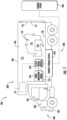
- FIG. 1 shows a schematic illustration of a transport refrigeration system 200 according to claim 1.
- FIG. 2 shows an enlarged schematic illustration of the transport refrigeration system 200 of FIG. 1 .
- the transport refrigeration system 200 is being illustrated as a truck or trailer system 100, as seen in FIG. 1 .
- the trailer system 100 includes a vehicle 102 integrally connected to a transport container 106.
- the vehicle 102 includes an operator's compartment or cab 104 and a propulsion motor 320 which acts as the drive system of the truck or trailer system 100.
- the propulsion motor 320 is configured to power the vehicle 102.
- the energy source that powers the propulsion motor 320 may be at least one of compressed natural gas, liquefied natural gas, gasoline, electricity, diesel, or a combination thereof.
- the propulsion motor 320 may be a combustion engine, an electric motor, or a hybrid motor (e.g., a combination of a combustion engine and an electric motor).
- the transport container 106 is coupled to the vehicle 102.
- the transport container 106 may be removably coupled to the vehicle 102.
- the transport container 106 is a refrigerated trailer and includes a top wall 108, a directly opposed bottom wall 110, opposed side walls 112, and a front wall 114, with the front wall 114 being closest to the vehicle 102.
- the transport container 106 further includes a door or doors 117 at a rear wall 116, opposite the front wall 114.
- the walls of the transport container 106 define a refrigerated cargo space 119.
- the refrigerated cargo space 119 may be subdivided into multiple different compartments that each have a different controlled environment (e.g., different temperature). It is appreciated by those of skill in the art that embodiments described herein may be applied to a tractor-trailer refrigerated system or non-trailer refrigeration such as, for example a rigid truck, a truck having refrigerated compartment.
- transport refrigeration systems 200 are used to transport and distribute perishable goods and environmentally sensitive goods (herein referred to as perishable goods 118).
- the perishable goods 118 may include but are not limited to fruits, vegetables, grains, beans, nuts, eggs, dairy, seed, flowers, meat, poultry, fish, ice, blood, pharmaceuticals, or any other suitable cargo requiring temperature controlled transport.
- the transport refrigeration system 200 according to claim 1 includes a transportation refrigeration unit 22, a refrigerant compression device 32, an electric motor 26 for driving the refrigerant compression device 32, and a controller 30.
- the transportation refrigeration unit 22 is in operative association with the refrigerated cargo space 112 and is configured to provide conditioned air to the transport container 106.
- the transportation refrigeration unit 22 functions, under the control of the controller 30, to establish and regulate a desired environmental parameters, such as, for example temperature, pressure, humidity, carbon dioxide, ethylene, ozone, light exposure, vibration exposure, and other conditions in the refrigerated cargo space 119, as known to one of ordinary skill in the art.
- the transportation refrigeration unit 22 is capable of providing a desired temperature and humidity range.
- the transportation refrigeration unit 22 includes a refrigerant compression device 32, a refrigerant heat rejection heat exchanger 34 (e.g., condenser), an expansion device 36, and a refrigerant heat absorption heat exchanger 38 (e.g., evaporator) connected in refrigerant flow communication in a closed loop refrigerant circuit and arranged in a conventional refrigeration cycle.
- the transportation refrigeration unit 22 also includes one or more fans 40 associated with the refrigerant heat rejection heat exchanger 34 and driven by fan motor(s) 42 and one or more fans 44 associated with the refrigerant heat absorption heat exchanger 38 and driven by fan motor(s) 46.
- the transportation refrigeration unit 22 may also include a heater 48 associated with the refrigerant heat absorption heat exchanger 38.
- the heater 48 may be an electric resistance heater. It is to be understood that other components (not shown) may be incorporated into the refrigerant circuit as desired, including for example, but not limited to, a suction modulation valve, a receiver, a filter/dryer, an economizer circuit. It is also to be understood that additional refrigeration circuits may be run in parallel and powered by the energy storage device 350 as desired.
- the refrigerant heat rejection heat exchanger 34 may, for example, comprise one or more refrigerant conveying coiled tubes or one or more tube banks formed of a plurality of refrigerant conveying tubes across flow path to the heat outlet 142.
- the fan(s) 40 are operative to pass air, typically ambient air, across the tubes of the refrigerant heat rejection heat exchanger 34 to cool refrigerant vapor passing through the tubes.
- the refrigerant heat rejection heat exchanger 34 may operate either as a refrigerant condenser, such as if the transportation refrigeration unit 22 is operating in a subcritical refrigerant cycle or as a refrigerant gas cooler, such as if the transportation refrigeration unit 22 is operating in a transcritical cycle.
- the refrigerant heat absorption heat exchanger 38 may, for example, also comprise one or more refrigerant conveying coiled tubes or one or more tube banks formed of a plurality of refrigerant conveying tubes extending across flow path from a return air intake 136.
- the fan(s) 44 are operative to pass air drawn from the refrigerated cargo space 119 across the tubes of the refrigerant heat absorption heat exchanger 38 to heat and evaporate refrigerant liquid passing through the tubes and cool the air.
- the air cooled in traversing the refrigerant heat rejection heat exchanger 38 is supplied back to the refrigerated cargo space 119 through a refrigeration unit outlet 140.
- air when used herein with reference to the atmosphere within the cargo box includes mixtures of air with other gases, such as for example, but not limited to, nitrogen or carbon dioxide, sometimes introduced into a refrigerated cargo box for transport of perishable produce.
- Airflow is circulated into and through the refrigerated cargo space 119 of the transport container 106 by means of the transportation refrigeration unit 22.
- a return airflow 134 flows into the transportation refrigeration unit 22 from the refrigerated cargo space 119 through the return air intake 136, and across the refrigerant heat absorption heat exchanger 38 via the fan 44, thus conditioning the return airflow 134 to a selected or predetermined temperature.
- the conditioned return airflow 134 now referred to as supply airflow 138, is supplied into the refrigerated cargo space 119 of the transport container 106 through the refrigeration unit outlet 140.
- Heat 135 is removed from the refrigerant heat rejection heat exchanger 34 through the heat outlet 142.
- the transportation refrigeration unit 22 may contain an external air inlet 144, as shown in FIG.
- the supply airflow 138 may cool the perishable goods 118 in the refrigerated cargo space 119 of the transport container 106. It is to be appreciated that the transportation refrigeration unit 22 can further be operated in reverse to warm the container 106 when, for example, the outside temperature is very low.
- the return air intake 136, the refrigeration unit outlet 140, the heat outlet 142, and the external air inlet 144 are configured as grilles to help prevent foreign objects from entering the transportation refrigeration unit 22.
- the transport refrigeration system 200 also includes a controller 30 configured for controlling the operation of the transport refrigeration system 200 including, but not limited to, the operation of various components of the refrigerant unit 22 to provide and maintain a desired thermal environment within the refrigerated cargo space 119.
- the controller 30 may also be able to selectively operate the electric motor 26.
- the controller 30 may be an electronic controller including a processor and an associated memory comprising computer-executable instructions that, when executed by the processor, cause the processor to perform various operations.
- the processor may be but is not limited to a single-processor or multi-processor system of any of a wide array of possible architectures, including field programmable gate array (FPGA), central processing unit (CPU), application specific integrated circuits (ASIC), digital signal processor (DSP) or graphics processing unit (GPU) hardware arranged homogenously or heterogeneously.
- the memory may be a storage device such as, for example, a random access memory (RAM), read only memory (ROM), or other electronic, optical, magnetic or any other computer readable medium.
- the transportation refrigeration unit 22 is powered by the energy storage device 350, which provides electrical energy to the transportation refrigeration unit 22 and will be discussed further below.
- the energy storage device 350 may include a battery system (e.g., a battery or bank of batteries), fuel cells, flow battery, and others devices capable of storing and outputting electric energy that may be direct current (DC).
- the energy storage device 350 may include a battery system, which may employ multiple batteries organized into battery banks.
- the energy storage device 350 may provide electrical energy to the transportation refrigeration unit 22 and the propulsion motor 320 of the vehicle 102.
- the energy storage device 350 may provide electrical energy solely to the transportation refrigeration unit 22, while the propulsion motor 320 of the vehicle 102 receives electrical energy from another source.
- the energy storage device 350 may be charged by a stationary charging station 386 such as, for example a wall 48V power outlet.
- the charging station 386 may provide single phase (e.g., level 2 charging capability) or three phase alternating current (AC) energy to the energy storage device 350. It is understood that the charging station 386 may have any phase charging and embodiments disclosed herein are not limited to single phase or three phase AC power.
- the single phase AC power may be a high voltage DC power, such as, for example, between 48 to 900 VDC.
- the energy storage device 350 is located outside of the transportation refrigeration unit 22, as shown in FIG. 1 . In another embodiment, the energy storage device 350 is located within the transportation refrigeration unit 22.
- the transportation refrigeration unit 22 has a plurality of electrical power demand loads on the energy storage device 350, including, but not limited to, the electric motor 26 for the refrigerant compression device 32, the fan motor 42 for the fan 40 associated with the refrigerant heat rejection heat exchanger 34, and the fan motor 46 for the fan 44 associated with the refrigerant heat absorption heat exchanger 38.
- various power converters 52 such as, for example, AC to DC rectifiers, DC to AC inverters, AC to AC voltage/frequency converters, and DC to DC voltage converters, may be employed in connection with the energy storage device 150 as appropriate.
- Each of the fan motors 42, 46 and the electric motor 26 is an AC motor and are thus electrically connected to the energy storage device 350 through a DC-to-AC variable invertor 370 that is configured to convert the DC electrical energy from the energy storage device to AC electrical energy in a variable continuous energy output to power the transportation refrigeration unit 22.
- the DC-to-AC variable invertor 370 electrically connects the energy storage device 350 to the transportation refrigeration unit 22.
- the DC-to-AC variable invertor 370 is configured to provide the variable continuous energy output to the transportation refrigeration unit 22 or specifically to the electric motor 26 of the transportation refrigeration unit 22.
- the DC-to-AC variable invertor 370 is configured to provide the variable continuous energy output in a range between the first energy output and the second energy output. It is understood that the values the first energy output is not limited to 35Hz and the second energy output is not limited to 65 Hz and the first energy output and the second energy output may vary in value based upon various factors, including, but not limited to, voltage of the various components of the transportation refrigeration unit 22, frequency acceptance of the various components of the transportation refrigeration unit 22, and characteristics of the various components of the transportation refrigeration unit 22.
- a power management module 310 is configured to control the variable continuous energy output of the DC-to-AC variable invertor 370 in response to transportation refrigeration unit parameters of the transportation refrigeration unit 22.
- the transportation refrigeration unit parameters may include but are not limited to set point, ambient temperature, delta T° between the temperature in the refrigerated cargo space 119 and the temperature set point of the transportation refrigeration unit 22, airflow rate into or out of the container 106, cooling capacity, temperature homogeneity in the container 106, doors 117 opening situation...etc.
- Transportation refrigeration unit parameters, such as delta T° may be important because a high delta T° may indicate that an increase energy is required for pull down or pull up.
- the power management module 310 is in electrical communication with the transportation refrigeration unit 22 and the DC-to-AC variable invertor 370.
- the power management module 310 may also be in electrical communication with the energy storage device 350.
- the power management module 310 may be configured to control and/or adjust energy output of the DC-to-AC variable invertor 370 in response to parameters of the energy storage device 350, including, but not limited to, a state of charge of the energy storage device 350 a state of health of the energy storage device 350, and a temperature of the energy storage device 350.
- the heater 48 also constitutes an electrical power demand load.
- the electric resistance heater 48 may be selectively operated by the controller 30 whenever a control temperature within the temperature controlled cargo box drops below a preset lower temperature limit, which may occur in a cold ambient environment. In such an event the controller 30 would activate the heater 48 to heat air circulated over the heater 48 by the fan(s) 44 associated with the refrigerant heat absorption heat exchanger 38.
- the heater 48 may also be used to de-ice the return air intake 136.
- the electric motor 26 being used to power the refrigerant compression device 32 also constitutes a demand load.
- the refrigerant compression device 32 may comprise a single-stage or multiple-stage compressor such as, for example, a reciprocating compressor or a scroll compressor.
- the transport refrigeration system 200 may also include a voltage sensor 28 to sense the voltage from the energy storage device 350.
- the energy storage device 350 is used to store electrical energy that is used to electrically power the transportation refrigeration unit 22.
- the energy storage device 350 is integrated within an energy management system 300.
- the energy management system 300 comprises the energy storage device 350 configured to provide electrical power to the transportation refrigeration unit, the electric motor 26 configured to power the transportation refrigeration unit 22, a power management module 310, and the DC-to-AC variable invertor 370.
- the power management module 310 may be incorporated into the transportation refrigeration unit 22 and/or the controller 30 of the transportation refrigeration unit 22. In an embodiment, the power management module 310 may be a computer program product (e.g., software) encoded within controller 30.
- the DC-to-AC variable invertor 370 is illustrated in FIG. 1 as being separate from the energy storage device 350 and the transportation refrigeration unit, in various embodiments, the DC-to-AC variable invertor 370 may be incorporated in the energy storage device 350 or the transportation refrigeration unit 22. In one embodiment, the DC-to-AC variable invertor is incorporated in the energy storage device 350. In another embodiment, the DC-to-AC variable invertor 370 is separate from the energy storage device 350 (i.e., not incorporated in the energy storage device 350).
- the power management module 310 may be an electronic controller including a processor and an associated memory comprising computer-executable instructions that, when executed by the processor, cause the processor to perform various operations.
- the processor may be but is not limited to a single-processor or multi-processor system of any of a wide array of possible architectures, including field programmable gate array (FPGA), central processing unit (CPU), application specific integrated circuits (ASIC), digital signal processor (DSP) or graphics processing unit (GPU) hardware arranged homogenously or heterogeneously.
- the memory may be a storage device such as, for example, a random access memory (RAM), read only memory (ROM), or other electronic, optical, magnetic or any other computer readable medium.
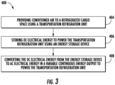
- FIG. 3 shows a flow process illustrating a method 400 according to claim 7 of operating a transport refrigeration system 200.
- conditioned air is provided to a refrigerated cargo space 119 using a transportation refrigeration unit 22.
- DC electrical energy to power the transportation refrigeration unit 22 is stored using an energy storage device 350.
- the DC electrical energy from the energy storage device 350 is converted to AC electrical energy in a variable continuous energy output to power the transportation refrigeration unit 22.
- the DC-to-AC variable invertor 370 electrically connecting the energy storage device 350 to the transportation refrigeration unit 22.
- the method 400 also comprises that the variable continuous energy output of the DC-to-AC variable invertor 370 is controlled in response to transportation refrigeration unit parameters using a power management module 310.
- the method 400 may also comprise that the variable continuous energy output of the DC-to-AC variable invertor 370 is adjusted in response to parameters of the energy storage device 350 using the power management module 310.
- the DC-to-AC variable invertor 370 is configured to provide the variable continuous energy output in a range between a first energy output and a second energy output. In another embodiment, the DC-to-AC variable invertor 370 is configured to provide the variable continuous energy output in range between a first energy output and a second energy output. In another embodiment, the DC-to-AC variable invertor 370 is incorporated in the energy storage device 350. In another embodiment, the DC-to-AC variable invertor is not incorporated in the energy storage device. In another embodiment, the energy storage device 350 includes a battery system.
Landscapes
- Engineering & Computer Science (AREA)
- Physics & Mathematics (AREA)
- Mechanical Engineering (AREA)
- Thermal Sciences (AREA)
- General Engineering & Computer Science (AREA)
- Chemical & Material Sciences (AREA)
- Combustion & Propulsion (AREA)
- Power Engineering (AREA)
- Devices That Are Associated With Refrigeration Equipment (AREA)
Description
- The embodiments herein generally relate to transport refrigeration systems according to claim 1 and the energy management of such transport refrigeration systems according to method claim 7.
- Typically, cold chain distribution systems are used to transport and distribute cargo, or more specifically perishable goods and environmentally sensitive goods (herein referred to as perishable goods) that may be susceptible to temperature, humidity, and other environmental factors. Perishable goods may include but are not limited to fruits, vegetables, grains, beans, nuts, eggs, dairy, seed, flowers, meat, poultry, fish, ice, and pharmaceuticals. Advantageously, cold chain distribution systems allow perishable goods to be effectively transported and distributed without damage or other undesirable effects.
- Refrigerated vehicles and trailers are commonly used to transport perishable goods in a cold chain distribution system. A transport refrigeration system is mounted to the vehicles or to the trailer in operative association with a cargo space defined within the vehicles or trailer for maintaining a controlled temperature environment within the cargo space.
- Conventionally, transport refrigeration systems used in connection with refrigerated vehicles and refrigerated trailers include a transportation refrigeration unit having a refrigerant compressor, a condenser with one or more associated condenser fans, an expansion device, and an evaporator with one or more associated evaporator fans, which are connected via appropriate refrigerant lines in a closed refrigerant flow circuit. Air or an air/ gas mixture is drawn from the interior volume of the cargo space by means of the evaporator fan(s) associated with the evaporator, passed through the airside of the evaporator in heat exchange relationship with refrigerant whereby the refrigerant absorbs heat from the air, thereby cooling the air. The cooled air is then supplied back to the cargo space.
- On commercially available transport refrigeration systems used in connection with refrigerated vehicles and refrigerated trailers, the compressor, and typically other components of the transportation refrigeration unit, must be powered during transit by a prime mover. In mechanically driven transport refrigeration systems the compressor is driven by the prime mover, either through a direct mechanical coupling or a belt drive, and other components, such as the condenser and evaporator fans are belt driven.
- Transport refrigeration systems may also be electrically driven. In an electrically driven transport refrigeration system, a prime mover carried on and considered part of the transport refrigeration system, drives an alternating (AC) synchronous generator that generates AC power. The generated AC power is used to power an electric motor for driving the refrigerant compressor of the transportation refrigeration unit and also powering electric AC fan motors for driving the condenser and evaporator motors and electric heaters associated with the evaporator. A more efficient method to power the electric motor is desired to reduce fuel usage. The relevant prior art documents are
US2017/349078A1 ,WO2018/226389A1 andWO2018/204591A1 , which disclose transport refrigeration systems being similar to the transport refrigeration system according to claim 1. - The present invention is disclosed in the independent claims. Further embodiments are disclosed in the dependent claims. According to the present invention a transport refrigeration system according to claim 1 is provided. The transport refrigeration system including: a transportation refrigeration unit configured to provide conditioned air to a refrigerated cargo space; an energy storage device configured to store DC electrical energy to power the transportation refrigeration unit; and a DC-to-AC variable invertor electrically connecting the energy storage device to the transportation refrigeration unit, the DC-to-AC variable invertor being configured to convert the DC electrical energy from the energy storage device to AC electrical energy in a variable continuous energy output to power the transportation refrigeration unit.
- According to the invention the transport refrigeration system includes a power management module in electrical communication with the DC-to-AC variable invertor and preferably with the transportation refrigeration unit, wherein the power management module is configured to control the variable continuous energy output of the DC-to-AC variable invertor in response to transportation refrigeration unit parameters.
- In addition to one or more of the features described above, further embodiments of the transport refrigeration system may include that the power management module is in electrical communication with the energy storage device wherein the power management module is configured to adjust the variable continuous energy output of the DC-to-AC variable invertor in response to parameters of the energy storage device.
- In addition to one or more of the features described above, further embodiments of the transport refrigeration system may include that the DC-to-AC variable invertor is incorporated in the energy storage device.
- In addition to one or more of the features described above, further embodiments of the transport refrigeration system may include that the DC-to-AC variable invertor is not incorporated in the energy storage device.
- In addition to one or more of the features described above, further embodiments of the transport refrigeration system may include that the energy storage device includes a battery system.
- According to the present invention, a method of operating a transport refrigeration system according to claim 7 is provided. The method including: providing conditioned air to a refrigerated cargo space using a transportation refrigeration unit; storing DC electrical energy to power the transportation refrigeration unit using an energy storage device; and converting the DC electrical energy from the energy storage device to AC electrical energy in a variable continuous energy output to power the transportation refrigeration unit using a DC-to-AC variable invertor.
- According to the present invention, the transport refrigeration system includes: controlling the variable continuous energy output of the DC-to-AC variable invertor in response to transportation refrigeration unit parameters using a power management module.
- In addition to one or more of the features described above further embodiments of the transport refrigeration system may include: adjusting the variable continuous energy output of the DC-to-AC variable invertor in response to parameters of the energy storage device using the power management module.
- In addition to one or more of the features described above, further embodiments of the transport refrigeration system may include that the DC-to-AC variable invertor is incorporated in the energy storage device.
- In addition to one or more of the features described above, further embodiments of the transport refrigeration system may include that the DC-to-AC variable invertor is not incorporated in the energy storage device.
- In addition to one or more of the features described above, further embodiments of the transport refrigeration system may include that the energy storage device includes a battery system.
- According to the present invention, a computer program product embodied on a non-transitory computer readable medium according to claim 10 is provided. The computer program product according to claim 10 including instructions that, when executed by a processor, cause the processor to perform operations as specified in claim 10.
- The operations further include: controlling the variable continuous energy output of the DC-to-AC variable invertor in response to transportation refrigeration unit parameters using a power management module.
- In addition to one or more of the features described above, further embodiments of the transport refrigeration system may include that the operations further include: adjusting the variable continuous energy output of the DC-to-AC variable invertor in response to parameters of the energy storage device using the power management module.
- These features and elements as well as the operation thereof will become more apparent in light of the following description and the accompanying drawings. It should be understood, however, that the following description and drawings are intended to be illustrative and explanatory in nature and non-limiting.
- Certain embodiments will now be described by way of example only and with reference to the accompanying drawings, which are listed below. The following descriptions should not be considered limiting in any way. With reference to the accompanying drawings, like elements are numbered alike:
-
FIG. 1 is a schematic illustration of a transport refrigeration system according to claim 1. -
FIG. 2 is an enlarged schematic illustration of a transportation refrigeration unit of the transport refrigeration system ofFIG. 1 ,; and -
FIG. 3 is a flow process illustrating a method according to claim 7 of operating the transport refrigeration system ofFIGS. 1 and2 . -
FIG. 1 shows a schematic illustration of atransport refrigeration system 200 according to claim 1. -
FIG. 2 shows an enlarged schematic illustration of thetransport refrigeration system 200 ofFIG. 1 . - The
transport refrigeration system 200 is being illustrated as a truck ortrailer system 100, as seen inFIG. 1 . Thetrailer system 100 includes avehicle 102 integrally connected to atransport container 106. Thevehicle 102 includes an operator's compartment orcab 104 and apropulsion motor 320 which acts as the drive system of the truck ortrailer system 100. Thepropulsion motor 320 is configured to power thevehicle 102. The energy source that powers thepropulsion motor 320 may be at least one of compressed natural gas, liquefied natural gas, gasoline, electricity, diesel, or a combination thereof. Thepropulsion motor 320 may be a combustion engine, an electric motor, or a hybrid motor (e.g., a combination of a combustion engine and an electric motor). Thetransport container 106 is coupled to thevehicle 102. Thetransport container 106 may be removably coupled to thevehicle 102. Thetransport container 106 is a refrigerated trailer and includes atop wall 108, a directly opposedbottom wall 110, opposedside walls 112, and afront wall 114, with thefront wall 114 being closest to thevehicle 102. Thetransport container 106 further includes a door ordoors 117 at arear wall 116, opposite thefront wall 114. The walls of thetransport container 106 define a refrigeratedcargo space 119. The refrigeratedcargo space 119 may be subdivided into multiple different compartments that each have a different controlled environment (e.g., different temperature). It is appreciated by those of skill in the art that embodiments described herein may be applied to a tractor-trailer refrigerated system or non-trailer refrigeration such as, for example a rigid truck, a truck having refrigerated compartment. - Typically,
transport refrigeration systems 200 are used to transport and distribute perishable goods and environmentally sensitive goods (herein referred to as perishable goods 118). Theperishable goods 118 may include but are not limited to fruits, vegetables, grains, beans, nuts, eggs, dairy, seed, flowers, meat, poultry, fish, ice, blood, pharmaceuticals, or any other suitable cargo requiring temperature controlled transport. Thetransport refrigeration system 200 according to claim 1 includes atransportation refrigeration unit 22, arefrigerant compression device 32, anelectric motor 26 for driving therefrigerant compression device 32, and acontroller 30. Thetransportation refrigeration unit 22 is in operative association with the refrigeratedcargo space 112 and is configured to provide conditioned air to thetransport container 106. Thetransportation refrigeration unit 22 functions, under the control of thecontroller 30, to establish and regulate a desired environmental parameters, such as, for example temperature, pressure, humidity, carbon dioxide, ethylene, ozone, light exposure, vibration exposure, and other conditions in the refrigeratedcargo space 119, as known to one of ordinary skill in the art. Thetransportation refrigeration unit 22 is capable of providing a desired temperature and humidity range. - The
transportation refrigeration unit 22 includes arefrigerant compression device 32, a refrigerant heat rejection heat exchanger 34 (e.g., condenser), anexpansion device 36, and a refrigerant heat absorption heat exchanger 38 (e.g., evaporator) connected in refrigerant flow communication in a closed loop refrigerant circuit and arranged in a conventional refrigeration cycle. Thetransportation refrigeration unit 22 also includes one ormore fans 40 associated with the refrigerant heatrejection heat exchanger 34 and driven by fan motor(s) 42 and one ormore fans 44 associated with the refrigerant heatabsorption heat exchanger 38 and driven by fan motor(s) 46. Thetransportation refrigeration unit 22 may also include aheater 48 associated with the refrigerant heatabsorption heat exchanger 38. In an embodiment, theheater 48 may be an electric resistance heater. It is to be understood that other components (not shown) may be incorporated into the refrigerant circuit as desired, including for example, but not limited to, a suction modulation valve, a receiver, a filter/dryer, an economizer circuit. It is also to be understood that additional refrigeration circuits may be run in parallel and powered by theenergy storage device 350 as desired. - The refrigerant heat
rejection heat exchanger 34 may, for example, comprise one or more refrigerant conveying coiled tubes or one or more tube banks formed of a plurality of refrigerant conveying tubes across flow path to theheat outlet 142. The fan(s) 40 are operative to pass air, typically ambient air, across the tubes of the refrigerant heatrejection heat exchanger 34 to cool refrigerant vapor passing through the tubes. The refrigerant heatrejection heat exchanger 34 may operate either as a refrigerant condenser, such as if thetransportation refrigeration unit 22 is operating in a subcritical refrigerant cycle or as a refrigerant gas cooler, such as if thetransportation refrigeration unit 22 is operating in a transcritical cycle. - The refrigerant heat
absorption heat exchanger 38 may, for example, also comprise one or more refrigerant conveying coiled tubes or one or more tube banks formed of a plurality of refrigerant conveying tubes extending across flow path from areturn air intake 136. The fan(s) 44 are operative to pass air drawn from the refrigeratedcargo space 119 across the tubes of the refrigerant heatabsorption heat exchanger 38 to heat and evaporate refrigerant liquid passing through the tubes and cool the air. The air cooled in traversing the refrigerant heatrejection heat exchanger 38 is supplied back to the refrigeratedcargo space 119 through arefrigeration unit outlet 140. It is to be understood that the term "air" when used herein with reference to the atmosphere within the cargo box includes mixtures of air with other gases, such as for example, but not limited to, nitrogen or carbon dioxide, sometimes introduced into a refrigerated cargo box for transport of perishable produce. - Airflow is circulated into and through the refrigerated
cargo space 119 of thetransport container 106 by means of thetransportation refrigeration unit 22. Areturn airflow 134 flows into thetransportation refrigeration unit 22 from the refrigeratedcargo space 119 through thereturn air intake 136, and across the refrigerant heatabsorption heat exchanger 38 via thefan 44, thus conditioning thereturn airflow 134 to a selected or predetermined temperature. The conditionedreturn airflow 134, now referred to assupply airflow 138, is supplied into therefrigerated cargo space 119 of thetransport container 106 through therefrigeration unit outlet 140.Heat 135 is removed from the refrigerant heatrejection heat exchanger 34 through theheat outlet 142. Thetransportation refrigeration unit 22 may contain anexternal air inlet 144, as shown inFIG. 2 , to aid in the removal ofheat 135 from the refrigerant heatrejection heat exchanger 34 by pulling inexternal air 137. Thesupply airflow 138 may cool theperishable goods 118 in the refrigeratedcargo space 119 of thetransport container 106. It is to be appreciated that thetransportation refrigeration unit 22 can further be operated in reverse to warm thecontainer 106 when, for example, the outside temperature is very low. In the illustrated embodiment, thereturn air intake 136, therefrigeration unit outlet 140, theheat outlet 142, and theexternal air inlet 144 are configured as grilles to help prevent foreign objects from entering thetransportation refrigeration unit 22. - The
transport refrigeration system 200 also includes acontroller 30 configured for controlling the operation of thetransport refrigeration system 200 including, but not limited to, the operation of various components of therefrigerant unit 22 to provide and maintain a desired thermal environment within the refrigeratedcargo space 119. Thecontroller 30 may also be able to selectively operate theelectric motor 26. Thecontroller 30 may be an electronic controller including a processor and an associated memory comprising computer-executable instructions that, when executed by the processor, cause the processor to perform various operations. The processor may be but is not limited to a single-processor or multi-processor system of any of a wide array of possible architectures, including field programmable gate array (FPGA), central processing unit (CPU), application specific integrated circuits (ASIC), digital signal processor (DSP) or graphics processing unit (GPU) hardware arranged homogenously or heterogeneously. The memory may be a storage device such as, for example, a random access memory (RAM), read only memory (ROM), or other electronic, optical, magnetic or any other computer readable medium. - The
transportation refrigeration unit 22 is powered by theenergy storage device 350, which provides electrical energy to thetransportation refrigeration unit 22 and will be discussed further below. Examples of theenergy storage device 350 may include a battery system (e.g., a battery or bank of batteries), fuel cells, flow battery, and others devices capable of storing and outputting electric energy that may be direct current (DC). Theenergy storage device 350 may include a battery system, which may employ multiple batteries organized into battery banks. In one embodiment, theenergy storage device 350 may provide electrical energy to thetransportation refrigeration unit 22 and thepropulsion motor 320 of thevehicle 102. In another embodiment, theenergy storage device 350 may provide electrical energy solely to thetransportation refrigeration unit 22, while thepropulsion motor 320 of thevehicle 102 receives electrical energy from another source. - The
energy storage device 350 may be charged by astationary charging station 386 such as, for example a wall 48V power outlet. The chargingstation 386 may provide single phase (e.g., level 2 charging capability) or three phase alternating current (AC) energy to theenergy storage device 350. It is understood that the chargingstation 386 may have any phase charging and embodiments disclosed herein are not limited to single phase or three phase AC power. In an embodiment, the single phase AC power may be a high voltage DC power, such as, for example, between 48 to 900 VDC. - In one embodiment, the
energy storage device 350 is located outside of thetransportation refrigeration unit 22, as shown inFIG. 1 . In another embodiment, theenergy storage device 350 is located within thetransportation refrigeration unit 22. Thetransportation refrigeration unit 22 has a plurality of electrical power demand loads on theenergy storage device 350, including, but not limited to, theelectric motor 26 for therefrigerant compression device 32, thefan motor 42 for thefan 40 associated with the refrigerant heatrejection heat exchanger 34, and thefan motor 46 for thefan 44 associated with the refrigerant heatabsorption heat exchanger 38. It is to be understood that, while not required,various power converters 52, such as, for example, AC to DC rectifiers, DC to AC inverters, AC to AC voltage/frequency converters, and DC to DC voltage converters, may be employed in connection with the energy storage device 150 as appropriate. Each of thefan motors electric motor 26 is an AC motor and are thus electrically connected to theenergy storage device 350 through a DC-to-AC variable invertor 370 that is configured to convert the DC electrical energy from the energy storage device to AC electrical energy in a variable continuous energy output to power thetransportation refrigeration unit 22. The DC-to-AC variable invertor 370 electrically connects theenergy storage device 350 to thetransportation refrigeration unit 22. - The DC-to-
AC variable invertor 370 is configured to provide the variable continuous energy output to thetransportation refrigeration unit 22 or specifically to theelectric motor 26 of thetransportation refrigeration unit 22. The DC-to-AC variable invertor 370 is configured to provide the variable continuous energy output in a range between the first energy output and the second energy output. It is understood that the values the first energy output is not limited to 35Hz and the second energy output is not limited to 65 Hz and the first energy output and the second energy output may vary in value based upon various factors, including, but not limited to, voltage of the various components of thetransportation refrigeration unit 22, frequency acceptance of the various components of thetransportation refrigeration unit 22, and characteristics of the various components of thetransportation refrigeration unit 22. - A
power management module 310 is configured to control the variable continuous energy output of the DC-to-AC variable invertor 370 in response to transportation refrigeration unit parameters of thetransportation refrigeration unit 22. The transportation refrigeration unit parameters may include but are not limited to set point, ambient temperature, delta T° between the temperature in the refrigeratedcargo space 119 and the temperature set point of thetransportation refrigeration unit 22, airflow rate into or out of thecontainer 106, cooling capacity, temperature homogeneity in thecontainer 106,doors 117 opening situation...etc. Transportation refrigeration unit parameters, such as delta T° may be important because a high delta T° may indicate that an increase energy is required for pull down or pull up. Thepower management module 310 is in electrical communication with thetransportation refrigeration unit 22 and the DC-to-AC variable invertor 370. Thepower management module 310 may also be in electrical communication with theenergy storage device 350. Thepower management module 310 may be configured to control and/or adjust energy output of the DC-to-AC variable invertor 370 in response to parameters of theenergy storage device 350, including, but not limited to, a state of charge of the energy storage device 350 a state of health of theenergy storage device 350, and a temperature of theenergy storage device 350. - By controlling energy output of the DC-to-
AC variable invertor 370 in response to parameters of thetransportation refrigeration unit 22 the efficiency of thetransportation refrigeration unit 22 is improved and the energy consumption of theenergy storage device 350 may be reduced or limited. - In the depicted embodiment, the
heater 48 also constitutes an electrical power demand load. Theelectric resistance heater 48 may be selectively operated by thecontroller 30 whenever a control temperature within the temperature controlled cargo box drops below a preset lower temperature limit, which may occur in a cold ambient environment. In such an event thecontroller 30 would activate theheater 48 to heat air circulated over theheater 48 by the fan(s) 44 associated with the refrigerant heatabsorption heat exchanger 38. Theheater 48 may also be used to de-ice thereturn air intake 136. Additionally, theelectric motor 26 being used to power therefrigerant compression device 32 also constitutes a demand load. Therefrigerant compression device 32 may comprise a single-stage or multiple-stage compressor such as, for example, a reciprocating compressor or a scroll compressor. Thetransport refrigeration system 200 may also include avoltage sensor 28 to sense the voltage from theenergy storage device 350. - As described above the
energy storage device 350 is used to store electrical energy that is used to electrically power thetransportation refrigeration unit 22. Theenergy storage device 350 is integrated within anenergy management system 300. Theenergy management system 300 comprises theenergy storage device 350 configured to provide electrical power to the transportation refrigeration unit, theelectric motor 26 configured to power thetransportation refrigeration unit 22, apower management module 310, and the DC-to-AC variable invertor 370. - In one example, while the
power management module 310 is illustrated inFIG. 1 as being separate from thetransportation refrigeration unit 22, in various embodiments, thepower management module 310 may be incorporated into thetransportation refrigeration unit 22 and/or thecontroller 30 of thetransportation refrigeration unit 22. In an embodiment, thepower management module 310 may be a computer program product (e.g., software) encoded withincontroller 30. In another example, while the DC-to-AC variable invertor 370 is illustrated inFIG. 1 as being separate from theenergy storage device 350 and the transportation refrigeration unit, in various embodiments, the DC-to-AC variable invertor 370 may be incorporated in theenergy storage device 350 or thetransportation refrigeration unit 22. In one embodiment, the DC-to-AC variable invertor is incorporated in theenergy storage device 350. In another embodiment, the DC-to-AC variable invertor 370 is separate from the energy storage device 350 (i.e., not incorporated in the energy storage device 350). - The
power management module 310 may be an electronic controller including a processor and an associated memory comprising computer-executable instructions that, when executed by the processor, cause the processor to perform various operations. The processor may be but is not limited to a single-processor or multi-processor system of any of a wide array of possible architectures, including field programmable gate array (FPGA), central processing unit (CPU), application specific integrated circuits (ASIC), digital signal processor (DSP) or graphics processing unit (GPU) hardware arranged homogenously or heterogeneously. The memory may be a storage device such as, for example, a random access memory (RAM), read only memory (ROM), or other electronic, optical, magnetic or any other computer readable medium. - Referring now to
FIG. 3 , with continued reference toFIGS. 1 and2 .FIG. 3 shows a flow process illustrating amethod 400 according to claim 7 of operating atransport refrigeration system 200. Atblock 404, conditioned air is provided to arefrigerated cargo space 119 using atransportation refrigeration unit 22. Atblock 406, DC electrical energy to power thetransportation refrigeration unit 22 is stored using anenergy storage device 350. Atblock 408, the DC electrical energy from theenergy storage device 350 is converted to AC electrical energy in a variable continuous energy output to power thetransportation refrigeration unit 22. The DC-to-AC variable invertor 370 electrically connecting theenergy storage device 350 to thetransportation refrigeration unit 22. - The
method 400 also comprises that the variable continuous energy output of the DC-to-AC variable invertor 370 is controlled in response to transportation refrigeration unit parameters using apower management module 310. Themethod 400 may also comprise that the variable continuous energy output of the DC-to-AC variable invertor 370 is adjusted in response to parameters of theenergy storage device 350 using thepower management module 310. - In an embodiment, the DC-to-
AC variable invertor 370 is configured to provide the variable continuous energy output in a range between a first energy output and a second energy output. In another embodiment, the DC-to-AC variable invertor 370 is configured to provide the variable continuous energy output in range between a first energy output and a second energy output. In another embodiment, the DC-to-AC variable invertor 370 is incorporated in theenergy storage device 350. In another embodiment, the DC-to-AC variable invertor is not incorporated in the energy storage device. In another embodiment, theenergy storage device 350 includes a battery system. - While the above description has described the flow process of
FIG. 3 in a particular order, it should be appreciated that unless otherwise specifically required in the attached claims that the ordering of the steps may be varied. - The present invention is disclosed in the independent claims. Further embodiments are disclosed in the dependent claims.
- The terminology used herein is for the purpose of describing particular embodiments only and is not intended to be limiting of the present disclosure. As used herein, the singular forms "a", "an" and "the" are intended to include the plural forms as well, unless the context clearly indicates otherwise. It will be further understood that the terms "comprises" and/or "comprising," when used in this specification, specify the presence of stated features, integers, steps, operations, elements, and/or components, but do not preclude the presence or addition of one or more other features, integers, steps, operations, element components, and/or groups thereof.
- While the present disclosure has been described with reference to an exemplary embodiment or embodiments, it will be understood by those skilled in the art that various changes may be made without departing from the scope of the present invention, which is defined by the claims. In addition, many modifications may be made to adapt a particular situation or material to the teachings of the present invention without departing from the scope thereof as defined by the claims. Therefore, it is intended that the present invention not be limited to the particular embodiment disclosed as the best mode contemplated for carrying out this present invention, but that the present invention will include all embodiments falling within the scope of the claims.
Claims (10)
- A transport refrigeration system (200) comprising:a transportation refrigeration unit (22) configured to provide conditioned air to a refrigerated cargo space (119);an energy storage device (350) configured to store DC electrical energy to power the transportation refrigeration unit;a DC-to-AC variable invertor (370) electrically connecting the energy storage device (350) to the transportation refrigeration unit (22); anda power management module (310) in electrical communication with the DC-to-AC variable invertor (370),characterized in that the power management module (310) is configured to control the DC-to-AC variable invertor (370) to convert the DC electrical energy from the energy storage device (350) to AC electrical energy in a variable and continuous energy output in response to transportation refrigeration unit parameters to power the transportation refrigeration unit (22).
- The transport refrigeration system (200) of claim 1, wherein the power management module (310) is in electrical communication with the transportation refrigeration unit (22).
- The transport refrigeration system (200) of claim 2, wherein the power management module (310) is in electrical communication with the energy storage device (350) wherein the power management module is configured to adjust the variable and continuous energy output of the DC-to-AC variable invertor (370) in response to parameters of the energy storage device (350).
- The transportation refrigeration system (200) of any preceding claim, wherein the DC-to-AC variable invertor (370) is incorporated in the energy storage device (350).
- The transportation refrigeration system (200) of any preceding claim, wherein the DC-to-AC variable invertor (370) is not incorporated in the energy storage device (350).
- The transportation refrigeration system (200) of any preceding claim, wherein the energy storage device (350) includes a battery system.
- A method of operating a transport refrigeration system (200) according to claim 1, the method comprising:providing conditioned air to a refrigerated cargo space (119) using a transportation refrigeration unit (22);storing DC electrical energy to power the transportation refrigeration unit using an energy storage device (350);converting the DC electrical energy from the energy storage device (350) to AC electrical energy in a variable and continuous energy output to power the transportation refrigeration unit (22) using a DC-to-AC variable invertor (370); andcontrolling the variable and continuous energy output of the DC-to-AC variable invertor (370) in response to transportation refrigeration unit parameters using a power management module (310).
- The method of claim 7, further comprising:
adjusting the variable and continuous energy output of the DC-to-AC variable invertor (370) in response to parameters of the energy storage device (350) using the power management module (310). - The method of claim 7 or 8, wherein the DC-to-AC variable invertor (370) is incorporated in the energy storage device (350); or wherein the DC-to-AC variable invertor (370) is not incorporated in the energy storage device (350); or wherein the energy storage device (350) includes a battery system.
- A computer program product embodied on a non-transitory computer readable medium, the computer program product including instructions that, when executed by a processor of a transport refrigeration system (200) according to claim 1, cause the transport refrigeration system (200) to perform operations comprising the method of any of claims 7 to 9.
Priority Applications (2)
| Application Number | Priority Date | Filing Date | Title |
|---|---|---|---|
| EP19305759.3A EP3750725B1 (en) | 2019-06-13 | 2019-06-13 | Transport refrigeration system and method of operating it |
| US16/899,051 US11548353B2 (en) | 2019-06-13 | 2020-06-11 | Battery powered transportation refrigeration unit with variable inverter |
Applications Claiming Priority (1)
| Application Number | Priority Date | Filing Date | Title |
|---|---|---|---|
| EP19305759.3A EP3750725B1 (en) | 2019-06-13 | 2019-06-13 | Transport refrigeration system and method of operating it |
Publications (2)
| Publication Number | Publication Date |
|---|---|
| EP3750725A1 EP3750725A1 (en) | 2020-12-16 |
| EP3750725B1 true EP3750725B1 (en) | 2024-07-24 |
Family
ID=67003408
Family Applications (1)
| Application Number | Title | Priority Date | Filing Date |
|---|---|---|---|
| EP19305759.3A Revoked EP3750725B1 (en) | 2019-06-13 | 2019-06-13 | Transport refrigeration system and method of operating it |
Country Status (2)
| Country | Link |
|---|---|
| US (1) | US11548353B2 (en) |
| EP (1) | EP3750725B1 (en) |
Families Citing this family (10)
| Publication number | Priority date | Publication date | Assignee | Title |
|---|---|---|---|---|
| US11584195B2 (en) * | 2019-11-05 | 2023-02-21 | Carrier Corporation | Time sharing control of transport refrigeration system |
| EP4071981B1 (en) | 2021-04-06 | 2023-05-31 | Carrier Fire & Security EMEA BV | Power management system for a transport refrigeration unit |
| EP4554079A3 (en) * | 2021-04-09 | 2025-06-18 | Carrier Corporation | Axle generator |
| EP4101695A1 (en) | 2021-06-08 | 2022-12-14 | Carrier Corporation | Power management system for a transport refrigeration unit |
| CN116691285A (en) * | 2022-02-28 | 2023-09-05 | 开利公司 | Transport refrigeration system for high temperature environment operation |
| US12555802B2 (en) * | 2022-03-01 | 2026-02-17 | Carrier Corporation | Hydrogen gas system for combined refrigeration and power |
| CN116691289A (en) * | 2022-03-01 | 2023-09-05 | 开利公司 | Modular Architecture for Fuel Cell Powered Transport Refrigeration |
| CN116691554A (en) * | 2022-03-01 | 2023-09-05 | 开利公司 | Fuel Cell Health and Safety System for Transport Refrigeration Units |
| US20230283099A1 (en) * | 2022-03-01 | 2023-09-07 | Carrier Corporation | Integrated fuel cell architecture for transportation refrigeration |
| US20240017619A1 (en) * | 2022-07-18 | 2024-01-18 | Carrier Corporation | Fuel cell architecture for transport refrigeration unit |
Citations (10)
| Publication number | Priority date | Publication date | Assignee | Title |
|---|---|---|---|---|
| US20010043052A1 (en) | 2000-05-17 | 2001-11-22 | Griffey Tammy M. | Apparatus and method for providing a mobile AC power supply |
| US20030106332A1 (en) | 2000-06-28 | 2003-06-12 | Hiroshi Okamoto | Refrigerating apparatus for use in vehicles, using an engine as power source |
| US20100027302A1 (en) | 2006-09-08 | 2010-02-04 | Siemens Aktiengesellschaft | Converter with reduced harmonic waves |
| US20120313431A1 (en) | 2011-06-09 | 2012-12-13 | Henry Shum | Battery with integrated power inverter |
| US20170349078A1 (en) | 2016-06-01 | 2017-12-07 | Cummins Inc. | Hybrid reefer systems |
| WO2018005957A1 (en) | 2016-06-30 | 2018-01-04 | Emerson Climate Technologies, Inc. | System and method of controlling compressor, evaporator fan, and condenser fan speeds during a battery mode of a refrigeration system for a container of a vehicle |
| WO2018005998A1 (en) | 2016-06-30 | 2018-01-04 | Emerson Climate Technologies, Inc. | Battery life prediction and monitoring |
| WO2018067839A1 (en) | 2016-10-05 | 2018-04-12 | Johnson Controls Technology Company | Variable speed drive with a battery |
| WO2018204591A1 (en) | 2017-05-05 | 2018-11-08 | Carrier Corporation | Hybrid-power transport refrigeration systems |
| WO2018226389A1 (en) | 2017-06-07 | 2018-12-13 | Carrier Corporation | Hybrid power conversion system for a refrigerated transport vehicle and method |
Family Cites Families (2)
| Publication number | Priority date | Publication date | Assignee | Title |
|---|---|---|---|---|
| DE102010003509A1 (en) * | 2010-03-31 | 2011-10-06 | Zf Friedrichshafen Ag | Power supply device and unit |
| US20210268908A1 (en) * | 2018-09-28 | 2021-09-02 | Carrier Corporation | Refrigeration system and energy storage device interface |
-
2019
- 2019-06-13 EP EP19305759.3A patent/EP3750725B1/en not_active Revoked
-
2020
- 2020-06-11 US US16/899,051 patent/US11548353B2/en active Active
Patent Citations (10)
| Publication number | Priority date | Publication date | Assignee | Title |
|---|---|---|---|---|
| US20010043052A1 (en) | 2000-05-17 | 2001-11-22 | Griffey Tammy M. | Apparatus and method for providing a mobile AC power supply |
| US20030106332A1 (en) | 2000-06-28 | 2003-06-12 | Hiroshi Okamoto | Refrigerating apparatus for use in vehicles, using an engine as power source |
| US20100027302A1 (en) | 2006-09-08 | 2010-02-04 | Siemens Aktiengesellschaft | Converter with reduced harmonic waves |
| US20120313431A1 (en) | 2011-06-09 | 2012-12-13 | Henry Shum | Battery with integrated power inverter |
| US20170349078A1 (en) | 2016-06-01 | 2017-12-07 | Cummins Inc. | Hybrid reefer systems |
| WO2018005957A1 (en) | 2016-06-30 | 2018-01-04 | Emerson Climate Technologies, Inc. | System and method of controlling compressor, evaporator fan, and condenser fan speeds during a battery mode of a refrigeration system for a container of a vehicle |
| WO2018005998A1 (en) | 2016-06-30 | 2018-01-04 | Emerson Climate Technologies, Inc. | Battery life prediction and monitoring |
| WO2018067839A1 (en) | 2016-10-05 | 2018-04-12 | Johnson Controls Technology Company | Variable speed drive with a battery |
| WO2018204591A1 (en) | 2017-05-05 | 2018-11-08 | Carrier Corporation | Hybrid-power transport refrigeration systems |
| WO2018226389A1 (en) | 2017-06-07 | 2018-12-13 | Carrier Corporation | Hybrid power conversion system for a refrigerated transport vehicle and method |
Non-Patent Citations (6)
| Title |
|---|
| AGRAWAL K C: "Static drives and energy saving", INDUSTRIAL POWER ENGINEERING AND APPLICATIONS HANDBOOK, 1 January 2007 (2007-01-01), pages 1 - 74, XP093252902 |
| ANONYMOUS: "Facts Worth Knowing about AC Drives", DANFOSS, 2 May 2019 (2019-05-02), pages 1 - 208, XP093252910, Retrieved from the Internet <URL:https://assets.danfoss.com/documents/latest/242341/AV446558536912en-000101.pdf> [retrieved on 20250221] |
| D11 -VFD Fundamentals - Kilowatt Classroom, LLC |
| M. POLKE: "Process Control Engineering", 1 January 2010, WILEY, ISBN: 978-3-527-61573-5, article ANONYMOUS: "The Process Control System and Its Elements: Process Actuator Systems", pages: 205 - 205, XP093250124, DOI: 10.1002/9783527615735.ch06 |
| MICHAEL VOLK: "Pump Characteristics and Applications 2nd Edition", 1 January 2005, TAYLOR & FRANCIS, ISBN: 9781420028355, article MICHAEL VOLK: "Energy Conservation and Life - Cycle Costs - Variable-Speed Pumping Systems", pages: 388 - 388, XP093252883, DOI: 10.1201/9781420028355 |
| PETERSEN STEVE : "Variable Frequency Drive Control Methods", YASKAWA, 5 May 2014 (2014-05-05), pages 1 - 7, XP093250089 |
Also Published As
| Publication number | Publication date |
|---|---|
| EP3750725A1 (en) | 2020-12-16 |
| US20200391574A1 (en) | 2020-12-17 |
| US11548353B2 (en) | 2023-01-10 |
Similar Documents
| Publication | Publication Date | Title |
|---|---|---|
| EP3750725B1 (en) | Transport refrigeration system and method of operating it | |
| EP3472541B1 (en) | Mechanical subcooler with battery supplement | |
| EP3472542B1 (en) | Transport refrigeration system with a battery system and corresponding method | |
| US11137173B2 (en) | Hot gas bypass for battery pack cold start | |
| US20210331559A1 (en) | Communication interface module for energy management | |
| EP3463961B1 (en) | Single point filling for an independent refrigeration unit driven by a separate engine | |
| US11345210B2 (en) | High voltage auxiliary power unit for a transportation refrigeration system | |
| US11976862B2 (en) | Electrical architecture for powering multiple transport refrigeration units | |
| EP4080708A1 (en) | Ac battery pack with integrated electronics and cooling | |
| US11472266B2 (en) | Engine exhaust gas cooling system for transport refrigeration system | |
| US10696139B2 (en) | Return air intake grille de-icing method | |
| US20260063350A1 (en) | Transport refrigeration system having multple power modes | |
| EP3668741A1 (en) | Common exhaust passage for transport refrigeration unit and vehicle | |
| EP3964373A1 (en) | Multi charging system architecture | |
| US11584195B2 (en) | Time sharing control of transport refrigeration system |
Legal Events
| Date | Code | Title | Description |
|---|---|---|---|
| PUAI | Public reference made under article 153(3) epc to a published international application that has entered the european phase |
Free format text: ORIGINAL CODE: 0009012 |
|
| STAA | Information on the status of an ep patent application or granted ep patent |
Free format text: STATUS: THE APPLICATION HAS BEEN PUBLISHED |
|
| AK | Designated contracting states |
Kind code of ref document: A1 Designated state(s): AL AT BE BG CH CY CZ DE DK EE ES FI FR GB GR HR HU IE IS IT LI LT LU LV MC MK MT NL NO PL PT RO RS SE SI SK SM TR |
|
| AX | Request for extension of the european patent |
Extension state: BA ME |
|
| STAA | Information on the status of an ep patent application or granted ep patent |
Free format text: STATUS: REQUEST FOR EXAMINATION WAS MADE |
|
| 17P | Request for examination filed |
Effective date: 20210616 |
|
| RBV | Designated contracting states (corrected) |
Designated state(s): AL AT BE BG CH CY CZ DE DK EE ES FI FR GB GR HR HU IE IS IT LI LT LU LV MC MK MT NL NO PL PT RO RS SE SI SK SM TR |
|
| STAA | Information on the status of an ep patent application or granted ep patent |
Free format text: STATUS: EXAMINATION IS IN PROGRESS |
|
| 17Q | First examination report despatched |
Effective date: 20220701 |
|
| P01 | Opt-out of the competence of the unified patent court (upc) registered |
Effective date: 20230527 |
|
| GRAP | Despatch of communication of intention to grant a patent |
Free format text: ORIGINAL CODE: EPIDOSNIGR1 |
|
| STAA | Information on the status of an ep patent application or granted ep patent |
Free format text: STATUS: GRANT OF PATENT IS INTENDED |
|
| RIC1 | Information provided on ipc code assigned before grant |
Ipc: F25D 29/00 20060101ALI20240119BHEP Ipc: F25D 11/00 20060101ALI20240119BHEP Ipc: F25B 27/00 20060101ALI20240119BHEP Ipc: B60H 1/32 20060101ALI20240119BHEP Ipc: B60H 1/00 20060101AFI20240119BHEP |
|
| INTG | Intention to grant announced |
Effective date: 20240212 |
|
| GRAS | Grant fee paid |
Free format text: ORIGINAL CODE: EPIDOSNIGR3 |
|
| GRAA | (expected) grant |
Free format text: ORIGINAL CODE: 0009210 |
|
| STAA | Information on the status of an ep patent application or granted ep patent |
Free format text: STATUS: THE PATENT HAS BEEN GRANTED |
|
| AK | Designated contracting states |
Kind code of ref document: B1 Designated state(s): AL AT BE BG CH CY CZ DE DK EE ES FI FR GB GR HR HU IE IS IT LI LT LU LV MC MK MT NL NO PL PT RO RS SE SI SK SM TR |
|
| REG | Reference to a national code |
Ref country code: GB Ref legal event code: FG4D |
|
| REG | Reference to a national code |
Ref country code: CH Ref legal event code: EP |
|
| REG | Reference to a national code |
Ref country code: IE Ref legal event code: FG4D Ref country code: DE Ref legal event code: R096 Ref document number: 602019055632 Country of ref document: DE |
|
| REG | Reference to a national code |
Ref country code: NL Ref legal event code: FP |
|
| REG | Reference to a national code |
Ref country code: LT Ref legal event code: MG9D |
|
| PG25 | Lapsed in a contracting state [announced via postgrant information from national office to epo] |
Ref country code: PT Free format text: LAPSE BECAUSE OF FAILURE TO SUBMIT A TRANSLATION OF THE DESCRIPTION OR TO PAY THE FEE WITHIN THE PRESCRIBED TIME-LIMIT Effective date: 20241125 |
|
| REG | Reference to a national code |
Ref country code: DE Ref legal event code: R026 Ref document number: 602019055632 Country of ref document: DE |
|
| REG | Reference to a national code |
Ref country code: AT Ref legal event code: MK05 Ref document number: 1706008 Country of ref document: AT Kind code of ref document: T Effective date: 20240724 |
|
| PLBI | Opposition filed |
Free format text: ORIGINAL CODE: 0009260 |
|
| PG25 | Lapsed in a contracting state [announced via postgrant information from national office to epo] |
Ref country code: PT Free format text: LAPSE BECAUSE OF FAILURE TO SUBMIT A TRANSLATION OF THE DESCRIPTION OR TO PAY THE FEE WITHIN THE PRESCRIBED TIME-LIMIT Effective date: 20241125 |
|
| PG25 | Lapsed in a contracting state [announced via postgrant information from national office to epo] |
Ref country code: NO Free format text: LAPSE BECAUSE OF FAILURE TO SUBMIT A TRANSLATION OF THE DESCRIPTION OR TO PAY THE FEE WITHIN THE PRESCRIBED TIME-LIMIT Effective date: 20241024 |
|
| PG25 | Lapsed in a contracting state [announced via postgrant information from national office to epo] |
Ref country code: GR Free format text: LAPSE BECAUSE OF FAILURE TO SUBMIT A TRANSLATION OF THE DESCRIPTION OR TO PAY THE FEE WITHIN THE PRESCRIBED TIME-LIMIT Effective date: 20241025 Ref country code: FI Free format text: LAPSE BECAUSE OF FAILURE TO SUBMIT A TRANSLATION OF THE DESCRIPTION OR TO PAY THE FEE WITHIN THE PRESCRIBED TIME-LIMIT Effective date: 20240724 Ref country code: PL Free format text: LAPSE BECAUSE OF FAILURE TO SUBMIT A TRANSLATION OF THE DESCRIPTION OR TO PAY THE FEE WITHIN THE PRESCRIBED TIME-LIMIT Effective date: 20240724 |
|
| PG25 | Lapsed in a contracting state [announced via postgrant information from national office to epo] |
Ref country code: BG Free format text: LAPSE BECAUSE OF FAILURE TO SUBMIT A TRANSLATION OF THE DESCRIPTION OR TO PAY THE FEE WITHIN THE PRESCRIBED TIME-LIMIT Effective date: 20240724 |
|
| PG25 | Lapsed in a contracting state [announced via postgrant information from national office to epo] |
Ref country code: LV Free format text: LAPSE BECAUSE OF FAILURE TO SUBMIT A TRANSLATION OF THE DESCRIPTION OR TO PAY THE FEE WITHIN THE PRESCRIBED TIME-LIMIT Effective date: 20240724 |
|
| 26 | Opposition filed |
Opponent name: THERMO KING LLC Effective date: 20241213 |
|
| PG25 | Lapsed in a contracting state [announced via postgrant information from national office to epo] |
Ref country code: IS Free format text: LAPSE BECAUSE OF FAILURE TO SUBMIT A TRANSLATION OF THE DESCRIPTION OR TO PAY THE FEE WITHIN THE PRESCRIBED TIME-LIMIT Effective date: 20241124 Ref country code: AT Free format text: LAPSE BECAUSE OF FAILURE TO SUBMIT A TRANSLATION OF THE DESCRIPTION OR TO PAY THE FEE WITHIN THE PRESCRIBED TIME-LIMIT Effective date: 20240724 |
|
| PG25 | Lapsed in a contracting state [announced via postgrant information from national office to epo] |
Ref country code: HR Free format text: LAPSE BECAUSE OF FAILURE TO SUBMIT A TRANSLATION OF THE DESCRIPTION OR TO PAY THE FEE WITHIN THE PRESCRIBED TIME-LIMIT Effective date: 20240724 |
|
| PG25 | Lapsed in a contracting state [announced via postgrant information from national office to epo] |
Ref country code: RS Free format text: LAPSE BECAUSE OF FAILURE TO SUBMIT A TRANSLATION OF THE DESCRIPTION OR TO PAY THE FEE WITHIN THE PRESCRIBED TIME-LIMIT Effective date: 20241024 Ref country code: ES Free format text: LAPSE BECAUSE OF FAILURE TO SUBMIT A TRANSLATION OF THE DESCRIPTION OR TO PAY THE FEE WITHIN THE PRESCRIBED TIME-LIMIT Effective date: 20240724 |
|
| PG25 | Lapsed in a contracting state [announced via postgrant information from national office to epo] |
Ref country code: RS Free format text: LAPSE BECAUSE OF FAILURE TO SUBMIT A TRANSLATION OF THE DESCRIPTION OR TO PAY THE FEE WITHIN THE PRESCRIBED TIME-LIMIT Effective date: 20241024 Ref country code: PL Free format text: LAPSE BECAUSE OF FAILURE TO SUBMIT A TRANSLATION OF THE DESCRIPTION OR TO PAY THE FEE WITHIN THE PRESCRIBED TIME-LIMIT Effective date: 20240724 Ref country code: NO Free format text: LAPSE BECAUSE OF FAILURE TO SUBMIT A TRANSLATION OF THE DESCRIPTION OR TO PAY THE FEE WITHIN THE PRESCRIBED TIME-LIMIT Effective date: 20241024 Ref country code: LV Free format text: LAPSE BECAUSE OF FAILURE TO SUBMIT A TRANSLATION OF THE DESCRIPTION OR TO PAY THE FEE WITHIN THE PRESCRIBED TIME-LIMIT Effective date: 20240724 Ref country code: IS Free format text: LAPSE BECAUSE OF FAILURE TO SUBMIT A TRANSLATION OF THE DESCRIPTION OR TO PAY THE FEE WITHIN THE PRESCRIBED TIME-LIMIT Effective date: 20241124 Ref country code: HR Free format text: LAPSE BECAUSE OF FAILURE TO SUBMIT A TRANSLATION OF THE DESCRIPTION OR TO PAY THE FEE WITHIN THE PRESCRIBED TIME-LIMIT Effective date: 20240724 Ref country code: GR Free format text: LAPSE BECAUSE OF FAILURE TO SUBMIT A TRANSLATION OF THE DESCRIPTION OR TO PAY THE FEE WITHIN THE PRESCRIBED TIME-LIMIT Effective date: 20241025 Ref country code: FI Free format text: LAPSE BECAUSE OF FAILURE TO SUBMIT A TRANSLATION OF THE DESCRIPTION OR TO PAY THE FEE WITHIN THE PRESCRIBED TIME-LIMIT Effective date: 20240724 Ref country code: ES Free format text: LAPSE BECAUSE OF FAILURE TO SUBMIT A TRANSLATION OF THE DESCRIPTION OR TO PAY THE FEE WITHIN THE PRESCRIBED TIME-LIMIT Effective date: 20240724 Ref country code: BG Free format text: LAPSE BECAUSE OF FAILURE TO SUBMIT A TRANSLATION OF THE DESCRIPTION OR TO PAY THE FEE WITHIN THE PRESCRIBED TIME-LIMIT Effective date: 20240724 Ref country code: AT Free format text: LAPSE BECAUSE OF FAILURE TO SUBMIT A TRANSLATION OF THE DESCRIPTION OR TO PAY THE FEE WITHIN THE PRESCRIBED TIME-LIMIT Effective date: 20240724 |
|
| PG25 | Lapsed in a contracting state [announced via postgrant information from national office to epo] |
Ref country code: DK Free format text: LAPSE BECAUSE OF FAILURE TO SUBMIT A TRANSLATION OF THE DESCRIPTION OR TO PAY THE FEE WITHIN THE PRESCRIBED TIME-LIMIT Effective date: 20240724 Ref country code: RO Free format text: LAPSE BECAUSE OF FAILURE TO SUBMIT A TRANSLATION OF THE DESCRIPTION OR TO PAY THE FEE WITHIN THE PRESCRIBED TIME-LIMIT Effective date: 20240724 Ref country code: SM Free format text: LAPSE BECAUSE OF FAILURE TO SUBMIT A TRANSLATION OF THE DESCRIPTION OR TO PAY THE FEE WITHIN THE PRESCRIBED TIME-LIMIT Effective date: 20240724 |
|
| PG25 | Lapsed in a contracting state [announced via postgrant information from national office to epo] |
Ref country code: EE Free format text: LAPSE BECAUSE OF FAILURE TO SUBMIT A TRANSLATION OF THE DESCRIPTION OR TO PAY THE FEE WITHIN THE PRESCRIBED TIME-LIMIT Effective date: 20240724 |
|
| PG25 | Lapsed in a contracting state [announced via postgrant information from national office to epo] |
Ref country code: CZ Free format text: LAPSE BECAUSE OF FAILURE TO SUBMIT A TRANSLATION OF THE DESCRIPTION OR TO PAY THE FEE WITHIN THE PRESCRIBED TIME-LIMIT Effective date: 20240724 |
|
| PG25 | Lapsed in a contracting state [announced via postgrant information from national office to epo] |
Ref country code: SK Free format text: LAPSE BECAUSE OF FAILURE TO SUBMIT A TRANSLATION OF THE DESCRIPTION OR TO PAY THE FEE WITHIN THE PRESCRIBED TIME-LIMIT Effective date: 20240724 Ref country code: IT Free format text: LAPSE BECAUSE OF FAILURE TO SUBMIT A TRANSLATION OF THE DESCRIPTION OR TO PAY THE FEE WITHIN THE PRESCRIBED TIME-LIMIT Effective date: 20240724 |
|
| PLAX | Notice of opposition and request to file observation + time limit sent |
Free format text: ORIGINAL CODE: EPIDOSNOBS2 |
|
| PGFP | Annual fee paid to national office [announced via postgrant information from national office to epo] |
Ref country code: NL Payment date: 20250520 Year of fee payment: 7 |
|
| PGFP | Annual fee paid to national office [announced via postgrant information from national office to epo] |
Ref country code: DE Payment date: 20250520 Year of fee payment: 7 |
|
| PGFP | Annual fee paid to national office [announced via postgrant information from national office to epo] |
Ref country code: GB Payment date: 20250520 Year of fee payment: 7 |
|
| PGFP | Annual fee paid to national office [announced via postgrant information from national office to epo] |
Ref country code: FR Payment date: 20250520 Year of fee payment: 7 |
|
| PG25 | Lapsed in a contracting state [announced via postgrant information from national office to epo] |
Ref country code: SE Free format text: LAPSE BECAUSE OF FAILURE TO SUBMIT A TRANSLATION OF THE DESCRIPTION OR TO PAY THE FEE WITHIN THE PRESCRIBED TIME-LIMIT Effective date: 20240724 |
|
| RDAF | Communication despatched that patent is revoked |
Free format text: ORIGINAL CODE: EPIDOSNREV1 |
|
| REG | Reference to a national code |
Ref country code: DE Ref legal event code: R064 Ref document number: 602019055632 Country of ref document: DE Ref country code: DE Ref legal event code: R103 Ref document number: 602019055632 Country of ref document: DE |
|
| REG | Reference to a national code |
Ref country code: CH Ref legal event code: H13 Free format text: ST27 STATUS EVENT CODE: U-0-0-H10-H13 (AS PROVIDED BY THE NATIONAL OFFICE) Effective date: 20260127 |
|
| PG25 | Lapsed in a contracting state [announced via postgrant information from national office to epo] |
Ref country code: MC Free format text: LAPSE BECAUSE OF FAILURE TO SUBMIT A TRANSLATION OF THE DESCRIPTION OR TO PAY THE FEE WITHIN THE PRESCRIBED TIME-LIMIT Effective date: 20240724 |
|
| PG25 | Lapsed in a contracting state [announced via postgrant information from national office to epo] |
Ref country code: LU Free format text: LAPSE BECAUSE OF NON-PAYMENT OF DUE FEES Effective date: 20250613 |
|
| REG | Reference to a national code |
Ref country code: BE Ref legal event code: MM Effective date: 20250630 |
|
| RDAG | Patent revoked |
Free format text: ORIGINAL CODE: 0009271 |
|
| STAA | Information on the status of an ep patent application or granted ep patent |
Free format text: STATUS: PATENT REVOKED |
|
| REG | Reference to a national code |
Ref country code: CH Ref legal event code: N12 Free format text: ST27 STATUS EVENT CODE: U-0-0-N10-N12 (AS PROVIDED BY THE NATIONAL OFFICE) Effective date: 20260325 |
|
| PG25 | Lapsed in a contracting state [announced via postgrant information from national office to epo] |
Ref country code: IE Free format text: LAPSE BECAUSE OF NON-PAYMENT OF DUE FEES Effective date: 20250613 |
|
| PG25 | Lapsed in a contracting state [announced via postgrant information from national office to epo] |
Ref country code: BE Free format text: LAPSE BECAUSE OF NON-PAYMENT OF DUE FEES Effective date: 20250630 |
|
| 27W | Patent revoked |
Effective date: 20251215 |