EP3750694A1 - Method and apparatus for fabricating contoured laminate structures - Google Patents
Method and apparatus for fabricating contoured laminate structures Download PDFInfo
- Publication number
- EP3750694A1 EP3750694A1 EP20187453.4A EP20187453A EP3750694A1 EP 3750694 A1 EP3750694 A1 EP 3750694A1 EP 20187453 A EP20187453 A EP 20187453A EP 3750694 A1 EP3750694 A1 EP 3750694A1
- Authority
- EP
- European Patent Office
- Prior art keywords
- tool
- forming
- modules
- ply carrier
- ply
- Prior art date
- Legal status (The legal status is an assumption and is not a legal conclusion. Google has not performed a legal analysis and makes no representation as to the accuracy of the status listed.)
- Granted
Links
Images





Classifications
-
- B—PERFORMING OPERATIONS; TRANSPORTING
- B29—WORKING OF PLASTICS; WORKING OF SUBSTANCES IN A PLASTIC STATE IN GENERAL
- B29C—SHAPING OR JOINING OF PLASTICS; SHAPING OF MATERIAL IN A PLASTIC STATE, NOT OTHERWISE PROVIDED FOR; AFTER-TREATMENT OF THE SHAPED PRODUCTS, e.g. REPAIRING
- B29C70/00—Shaping composites, i.e. plastics material comprising reinforcements, fillers or preformed parts, e.g. inserts
- B29C70/04—Shaping composites, i.e. plastics material comprising reinforcements, fillers or preformed parts, e.g. inserts comprising reinforcements only, e.g. self-reinforcing plastics
- B29C70/28—Shaping operations therefor
- B29C70/30—Shaping by lay-up, i.e. applying fibres, tape or broadsheet on a mould, former or core; Shaping by spray-up, i.e. spraying of fibres on a mould, former or core
- B29C70/38—Automated lay-up, e.g. using robots, laying filaments according to predetermined patterns
-
- B—PERFORMING OPERATIONS; TRANSPORTING
- B29—WORKING OF PLASTICS; WORKING OF SUBSTANCES IN A PLASTIC STATE IN GENERAL
- B29C—SHAPING OR JOINING OF PLASTICS; SHAPING OF MATERIAL IN A PLASTIC STATE, NOT OTHERWISE PROVIDED FOR; AFTER-TREATMENT OF THE SHAPED PRODUCTS, e.g. REPAIRING
- B29C69/00—Combinations of shaping techniques not provided for in a single one of main groups B29C39/00 - B29C67/00, e.g. associations of moulding and joining techniques; Apparatus therefore
-
- B—PERFORMING OPERATIONS; TRANSPORTING
- B29—WORKING OF PLASTICS; WORKING OF SUBSTANCES IN A PLASTIC STATE IN GENERAL
- B29C—SHAPING OR JOINING OF PLASTICS; SHAPING OF MATERIAL IN A PLASTIC STATE, NOT OTHERWISE PROVIDED FOR; AFTER-TREATMENT OF THE SHAPED PRODUCTS, e.g. REPAIRING
- B29C70/00—Shaping composites, i.e. plastics material comprising reinforcements, fillers or preformed parts, e.g. inserts
- B29C70/04—Shaping composites, i.e. plastics material comprising reinforcements, fillers or preformed parts, e.g. inserts comprising reinforcements only, e.g. self-reinforcing plastics
- B29C70/06—Fibrous reinforcements only
-
- B—PERFORMING OPERATIONS; TRANSPORTING
- B29—WORKING OF PLASTICS; WORKING OF SUBSTANCES IN A PLASTIC STATE IN GENERAL
- B29C—SHAPING OR JOINING OF PLASTICS; SHAPING OF MATERIAL IN A PLASTIC STATE, NOT OTHERWISE PROVIDED FOR; AFTER-TREATMENT OF THE SHAPED PRODUCTS, e.g. REPAIRING
- B29C70/00—Shaping composites, i.e. plastics material comprising reinforcements, fillers or preformed parts, e.g. inserts
- B29C70/04—Shaping composites, i.e. plastics material comprising reinforcements, fillers or preformed parts, e.g. inserts comprising reinforcements only, e.g. self-reinforcing plastics
- B29C70/28—Shaping operations therefor
- B29C70/54—Component parts, details or accessories; Auxiliary operations, e.g. feeding or storage of prepregs or SMC after impregnation or during ageing
- B29C70/541—Positioning reinforcements in a mould, e.g. using clamping means for the reinforcement
-
- B—PERFORMING OPERATIONS; TRANSPORTING
- B29—WORKING OF PLASTICS; WORKING OF SUBSTANCES IN A PLASTIC STATE IN GENERAL
- B29D—PRODUCING PARTICULAR ARTICLES FROM PLASTICS OR FROM SUBSTANCES IN A PLASTIC STATE
- B29D99/00—Subject matter not provided for in other groups of this subclass
- B29D99/0003—Producing profiled members, e.g. beams
-
- B—PERFORMING OPERATIONS; TRANSPORTING
- B29—WORKING OF PLASTICS; WORKING OF SUBSTANCES IN A PLASTIC STATE IN GENERAL
- B29K—INDEXING SCHEME ASSOCIATED WITH SUBCLASSES B29B, B29C OR B29D, RELATING TO MOULDING MATERIALS OR TO MATERIALS FOR MOULDS, REINFORCEMENTS, FILLERS OR PREFORMED PARTS, e.g. INSERTS
- B29K2105/00—Condition, form or state of moulded material or of the material to be shaped
- B29K2105/06—Condition, form or state of moulded material or of the material to be shaped containing reinforcements, fillers or inserts
- B29K2105/12—Condition, form or state of moulded material or of the material to be shaped containing reinforcements, fillers or inserts of short lengths, e.g. chopped filaments, staple fibres or bristles
-
- B—PERFORMING OPERATIONS; TRANSPORTING
- B29—WORKING OF PLASTICS; WORKING OF SUBSTANCES IN A PLASTIC STATE IN GENERAL
- B29K—INDEXING SCHEME ASSOCIATED WITH SUBCLASSES B29B, B29C OR B29D, RELATING TO MOULDING MATERIALS OR TO MATERIALS FOR MOULDS, REINFORCEMENTS, FILLERS OR PREFORMED PARTS, e.g. INSERTS
- B29K2307/00—Use of elements other than metals as reinforcement
- B29K2307/04—Carbon
-
- B—PERFORMING OPERATIONS; TRANSPORTING
- B29—WORKING OF PLASTICS; WORKING OF SUBSTANCES IN A PLASTIC STATE IN GENERAL
- B29L—INDEXING SCHEME ASSOCIATED WITH SUBCLASS B29C, RELATING TO PARTICULAR ARTICLES
- B29L2031/00—Other particular articles
- B29L2031/30—Vehicles, e.g. ships or aircraft, or body parts thereof
- B29L2031/3076—Aircrafts
- B29L2031/3082—Fuselages
-
- Y—GENERAL TAGGING OF NEW TECHNOLOGICAL DEVELOPMENTS; GENERAL TAGGING OF CROSS-SECTIONAL TECHNOLOGIES SPANNING OVER SEVERAL SECTIONS OF THE IPC; TECHNICAL SUBJECTS COVERED BY FORMER USPC CROSS-REFERENCE ART COLLECTIONS [XRACs] AND DIGESTS
- Y02—TECHNOLOGIES OR APPLICATIONS FOR MITIGATION OR ADAPTATION AGAINST CLIMATE CHANGE
- Y02T—CLIMATE CHANGE MITIGATION TECHNOLOGIES RELATED TO TRANSPORTATION
- Y02T50/00—Aeronautics or air transport
- Y02T50/40—Weight reduction
-
- Y—GENERAL TAGGING OF NEW TECHNOLOGICAL DEVELOPMENTS; GENERAL TAGGING OF CROSS-SECTIONAL TECHNOLOGIES SPANNING OVER SEVERAL SECTIONS OF THE IPC; TECHNICAL SUBJECTS COVERED BY FORMER USPC CROSS-REFERENCE ART COLLECTIONS [XRACs] AND DIGESTS
- Y10—TECHNICAL SUBJECTS COVERED BY FORMER USPC
- Y10T—TECHNICAL SUBJECTS COVERED BY FORMER US CLASSIFICATION
- Y10T156/00—Adhesive bonding and miscellaneous chemical manufacture
- Y10T156/10—Methods of surface bonding and/or assembly therefor
- Y10T156/1002—Methods of surface bonding and/or assembly therefor with permanent bending or reshaping or surface deformation of self sustaining lamina
Definitions
- the present disclosure generally relates to fabrication of laminates, especially those that are contoured, and deals more particularly with a method and apparatus for automated layup and forming of different laminate structures within a family of structures having common features.
- contoured composite fuselage barrel frame sections may be formed using a two-piece assembly comprising a channel section frame and a shear tie, mechanically fastened together. More recently, one-piece composite frame sections have been proposed that employ braided composites, however this fabrication approach is time consuming and labor intensive, and may result in a frame that is heavier than desired. The problem of fabricating one-piece frame sections is more difficult in high production rate environments where production flow times may be important to achieve manufacturing efficiencies.
- the disclosed embodiments provide a method and apparatus for producing different composite laminate structures within a family of structures having common features.
- the apparatus comprises an automated, reconfigurable composite forming system especially designed to form unidirectional prepreg tape in the production of structural members, such as aircraft fuselage frames.
- the apparatus comprises a plurality of substantially identical forming modules linked together to form a single former that may be reconfigured to conform to a wide range of tools defining corresponding structural shapes.
- Each of the forming modules possesses the ability to locally adapt or transform to the unique design, shape or features of the tool.
- the apparatus may be employed to fabricate multi-ply composite frame sections having a Z cross-sectional shape, by laying up, forming and compacting each ply of the frame section.
- the plies are formed from an inner chord outwardly to an outer chord, sometimes referred to as a shear tie.
- Each of the forming modules adapts to the local shape of the tool.
- the modules are linked together in a manner to form a single former that adjusts to the entire tool. Different tool arc lengths can be accommodated by adding or removing forming modules. It is not necessary that the forming modules exactly match the total arc length of a tool in those cases where the structure is contoured.
- the apparatus employs an adaptive control system based on a generic structural shape profile of structures within a family of structures.
- the adaptive control system forms each ply of the structure based on a combination of force feedback and positional control.
- Each forming module has two servo axes and employs force feedback on one of these two axes at a time.
- the use of force feedback is dependent upon the area of the structure being formed.
- the feedback switches back and forth between the two axes. Switching between the two axes is controlled by the adaptive system and is determined by generic shape parameters of the structure being formed. Reliance on a generic motion profile allows the apparatus to form any of a multiplicity of unique structures, ply-by-ply without the need for NC (numerical control) programming.
- the apparatus is easily scalable to fabricate structures of different sizes within a family of structures by adding or removing forming modules, and arranging the modules to substantially match corresponding tool shapes.
- a system for fabricating a plurality of unique parts.
- the system comprises a plurality of unique layup tools respectively corresponding to the plurality of parts to be fabricated and, a plurality of former modules configured to be combined together to define a plurality of unique formers respectively corresponding to the plurality of parts and the plurality of layup tools.
- Each of the formers is adapted for laying down material on a corresponding one of the layup tools to form a corresponding one of the parts.
- the former modules are substantially identical, and each of the plurality of unique formers is configured by coupling each of the substantially identical former modules to the corresponding unique layup tool.
- the former modules are linked together and are mounted on bases allowing the former modules to move in multiple directions.
- Each of the former modules includes a forming head adapted to form the material on a corresponding one of the layup tools.
- Each of the forming heads includes compliance.
- the part may be a laminated structure, and the laminated structure may be a carbon fiber reinforced plastic.
- apparatus for fabricating each of a plurality of differing laminate structures in a family of structures having common features.
- the apparatus comprises a plurality of separate fabrication modules each locally adapted to fabricate a section of the laminate structure on a corresponding tool.
- the fabrication modules are reconfigurable to fabricate each of the laminate structures in the family thereof.
- the apparatus also includes a controller for controlling and coordinating automated operation of the fabrication modules.
- the apparatus may further comprise a forming member adapted for forming laminate plies over the tool.
- the forming member extends along a length of the fabrication modules, and is mounted on each of the fabrication modules for movement over the tool along at least two axes.
- the forming member is continuous along the length of the fabrication modules.
- the forming member is controlled along two axes, but has a shape that adapts to changes between different areas of the structure being formed, such as, in the case of a one-piece aircraft fuselage frame, between an inner chord radius and a shear tie radius of the frame.
- Each of the fabrication modules includes a track in which a portion of the forming member is locally mounted.
- a single forming member may be used to fabricate a particular structure, however the forming member is removably mounted in the track to allow interchangeability of a plurality of forming members respectively having different shapes to fabricate differently shaped structures.
- the track allows for lateral (or tangential) slip of the forming member relative to each module as the arc length of the structure changes as the forming member moves over the structure.
- the forming member is adapted to sweep laminate plies over the tool, and includes compliance.
- Each of the fabrication modules includes a clamp adapted for clamping a portion of a laminate ply against a portion of the tool.
- Each of the fabrication modules includes a powered drive coupled with the forming member for sweeping the forming member over the laminate plies and compacting laminate plies on the tool.
- the apparatus may further comprise a flexible ply carrier adapted to hold at least one laminate ply thereon, wherein each of the fabrication modules includes a pair of spaced apart tracks adapted to releasably hold the ply carrier, and a ply carrier control assembly for holding the ply carrier in tension as the forming member forms the ply over the tool.
- the forming member is engageable with the ply carrier to sweep the ply carrier along with the ply thereon over the tool, and the ply carrier control assembly includes drives for adjusting the position ply carrier along two axes.
- Each of the fabrication modules further includes a force sensor for sensing a level of force applied to the laminate plies by the forming member, and a position sensor for sensing the position of the forming member.
- Each of the fabrication modules further includes a clamp for clamping the fabrication module to the tool.
- the apparatus may also comprise linkage between the fabrication modules for coupling the fabrication modules together and for aligning the fabrication modules relative to the tool. The linkage is configured to allow the forming modules to rotate along an arc that is substantially the same as the retracted arc of the continuously extending forming member.
- the fabrication modules are substantially identical and interchangeable with each other.
- the apparatus also includes a central controller for controlling and coordinating the operation of the fabrication modules to collectively fabricate the laminate structure.
- a method is provided of fabricating a plurality of differing parts in a family of parts having common features, wherein each of the parts is fabricated using a unique tool.
- the method comprises arranging a plurality of separate, substantially identical fabrication modules to substantially match a tool on which one of the parts is to be fabricated, and adapting each of the fabrication modules to a local section of the tool.
- the method further comprises controlling and coordinating operation of the fabrication modules to fabricate portions of the part over a corresponding section of the tool.
- Arranging the fabrication modules includes moving each of the fabrication modules into proximity to the tool, and linking the fabrication modules together.
- the method may further comprise clamping each of the fabrication modules to the tool.
- Adapting each of the fabrication modules includes learning, by each of the fabrication modules, the location of surfaces on the tool on which the part is to be fabricated.
- the method may also comprise sweeping materials across the surfaces of the tool using a forming member, and using the forming member to learn the location of the surfaces on the tool. Learning the location of the surfaces includes sensing the position of the forming member as the forming member sweeps materials across the surfaces of the tool, and recording the sensed position of the forming member.
- Adapting each of the fabrication modules includes adjusting the elevation of the fabrication modules to a common waterline.
- the method may further comprise forming a continuous spline along all of the fabrication modules. Forming the continuous spline includes mounting a continuous forming member along substantially the entire length of the fabrication modules.
- Each of the fabrication modules may be a laminate ply former module for forming a local section of a ply.
- Arranging the fabrication modules includes linking the fabrication modules together to form a single laminate ply former.
- a method of fabricating a composite laminate structure.
- the method comprises arranging a plurality of substantially identical forming modules to generally match a tool on which composite plies are to be formed to fabricate the laminate structure, and linking the forming modules together to form a single former for forming an entire composite laminate structure.
- the method further comprises mounting a continuous forming member on the forming modules, the continuous forming member defining a spline extending substantially the entire length of the former, and using the forming member to form and compact the composite plies on the tool.
- the method may also include placing the composite plies on a ply carrier. The forming member is used to engage and sweep the ply carrier along with the plies over the tool.
- a forming module for forming a composite laminate part over a tool.
- the forming module comprises a base and a ply carrier control assembly adapted for controlling the position of a flexible ply carrier on which composite resin plies are mounted.
- the forming module further comprises a head section mounted on the base and adapted for automatically forming the composite resin plies from the ply carrier onto the tool.
- the base is adapted to move over a supporting surface, and the head section includes adaptive control for learning a profile of the tool.
- the forming module may further include a clamp for clamping the head section to the tool, and an automatically controlled forming member for forming the plies over the tool.
- a system for fabricating a plurality of unique parts comprising: a plurality of unique layup tools respectively corresponding to the plurality of parts to be fabricated, and, a plurality of former modules configured to be combined together to define a plurality of unique formers respectively corresponding to the plurality of parts and the plurality of layup tools, each of the formers being adapted for laying down material on a corresponding one of the layup tools to form a corresponding one of the parts.
- the former modules are substantially identical, and each of the plurality of unique formers is configured by coupling each of the substantially identical former modules to the corresponding unique layup tool.
- each of the former modules includes a forming head section adapted to form the material on a corresponding one of the layup tools.
- each of the forming head sections includes compliance.
- the compliance is removed when the former modules are coupled to the layup tool.
- the part is a laminated structure.
- the system wherein the part is a carbon fiber reinforced plastic.
- an apparatus for fabricating each of a plurality of differing laminate structures in a family of structures having common features comprising: a plurality of separate fabrication modules each locally adapted to fabricate a section of the laminate structure on a corresponding tool, the fabrication modules being reconfigurable to fabricate each of the laminate structures in the family thereof, and a controller for controlling and coordinating automated operation of the fabrication modules.
- the apparatus further comprises a forming member adapted for forming laminate plies over the tool, the forming member extending along a length of the fabrication modules, the forming member being mounted on each of the fabrication modules for movement over the tool along at least two axes.
- each of the fabrication modules includes a track in which a portion of the forming member is local mounted.
- the apparatus wherein the forming member is removably mounted in the tracks to allow interchangeability of a plurality of forming members respectively having different shapes.
- the apparatus wherein the forming member is adapted to sweep laminate plies over the tool, and includes compliance.
- each of the fabrication modules includes a clamp adapted for clamping a portion of a laminate ply against a portion of the tool.
- each of the fabrication modules includes a powered drive coupled with the forming member for sweeping the forming member over the laminate plies and compacting laminate plies on the tool.
- the apparatus further comprises: a flexible ply carrier adapted to hold at least one laminate ply thereon, and wherein each of the fabrication modules includes a pair of spaced apart tracks adapted to releasably hold the ply carrier, and a ply carrier control assembly for holding the ply carrier in tension as the forming member forms the ply over the tool.
- the apparatus wherein: the forming member is engageable with the ply carrier to sweep the ply carrier along with the ply thereon over the tool, and the ply carrier control assembly includes drives for adjusting a position of the ply carrier along two axes.
- each of the fabrication modules further includes: a force sensor for sensing a level of force applied to the laminate plies by the forming member, and a position sensor for sensing the position of the forming member.
- each of the fabrication modules includes a clamp for clamping the fabrication module to the tool.
- the apparatus further comprises linkage between the fabrication modules for rigidly coupling the fabrication modules together and for aligning the fabrication modules relative to the tool.
- the apparatus wherein the fabrication modules are substantially identical and interchangeable with each other.
- the apparatus further comprises a central controller for controlling and coordinating the operation of the fabrication modules to collectively fabricate the laminate structure.
- a method of fabricating each of a plurality of differing parts in a family of parts having common features, wherein each of the parts is fabricated using a unique tool comprising: arranging a plurality of separate, substantially identical fabrication modules to substantially match a tool on which one of the parts is to be fabricated, adapting each of the fabrication modules to a local section of the tool, and, controlling and coordinating operation of the fabrication modules to fabricate portions of the part over a corresponding section of the tool.
- arranging the fabrication modules includes: moving each of the fabrication modules into proximity to the tool, and rigidly linking the fabrication modules together.
- the method further comprises: clamping each of the fabrication modules to the tool.
- the method wherein adapting the each of the fabrication modules includes learning, by each of the fabrication modules, the location of surfaces on the tool on which the part is to be fabricated.
- the method further comprises: sweeping materials across the surfaces of the tool using a forming member, and using the forming member to learn the location of the surfaces on the tool.
- learning the location of the surfaces includes: sensing a position of the forming member as the forming member sweeps materials across the surfaces of the tool, and recording the sensed position of the forming member.
- adapting each of the fabrication modules includes adjusting the elevation of the fabrication modules to a common waterline.
- the method further comprises: forming a continuous spline along all of the fabrication modules.
- each of the fabrication modules is a laminate ply former module for forming a local section of a ply
- arranging the fabrication modules includes linking the fabrication modules together to form a single laminate ply former.
- a method of fabricating a composite laminate structure comprising: arranging a plurality of substantially identical forming modules to generally match a tool on which composite plies are to be formed to fabricate the laminate structure, linking the forming modules together to form a single former for forming an entire composite laminate structure, mounting a continuous forming member on the forming modules, the continuous forming member defining a spline extending substantially the entire length of the former, and using the forming member to form and compact the composite plies on the tool.
- the method further comprises: placing the composite plies on a ply carrier, and wherein using the forming member includes engaging and sweeping the ply carrier along with the plies over the tool.
- a forming module for forming a composite laminate part over a tool, comprising: a base, a ply carrier control assembly adapted for controlling the position of a flexible ply carrier on which composite resin plies are mounted, and a head section mounted on the base and adapted for automatically forming the composite resin plies from the ply carrier onto the tool.
- the forming module wherein the base is adapted to move over a supporting surface.
- the forming module further comprises a clamp for clamping the head section to the tool.
- the head section includes an adaptive control for learning a profile of the tool.
- the forming module further comprises a nosepiece for engaging the ply carrier and forming the plies onto the tool, the nosepiece being mounted for movement on the head section along first and second axes.
- the head section includes a load cell for sensing the magnitude of a force applied by the nosepiece to the ply carrier and the tool.
- the base includes a powered slide assembly for moving the head section along a third axis substantially orthogonal to the first and second axes.
- the forming module wherein the head section includes at least one position sensor for sensing the position of the nosepiece.
- the nosepiece has compliance allowing the nosepiece to conform to features of the tool.
- the forming module wherein the ply carrier control assembly includes a device for controlling tension on the flexible ply carrier.
- the forming module wherein the ply carrier control assembly is mounted on the head section.
- the forming module wherein the ply carrier control assembly includes an automatically controlled, motorized arm for supporting and displacing the ply carrier as the plies are being formed from the ply carrier onto the tool.
- the head section includes a datum locator for locating a datum on the tool.
- a system 38 is provided for fabricating any of a plurality of unique parts 54 within a family 56 of parts 54 having common features or characteristics.
- the unique parts 54 may be fabricated using corresponding, unique tools 48, which may be layup tools, and a combination 43 of fabrication modules 42 arranged and configured to form a fabricator 40, sometimes hereinafter also referred to as a former 40.
- the fabrication modules 42 may be identical and interchangeable.
- the number and arrangement of the fabrication modules 42 is matched to the particular tool 48 required to fabricate a particular part 54.
- the fabricator 40 fabricates the part 54 by placing and forming material 46 on the particular tool 48.
- the part 54 may be a multi-ply composite laminate, and the material 46 may be a carbon fiber reinforced plastic (CFRP).
- CFRP carbon fiber reinforced plastic
- Figure 2 illustrates one embodiment of the system 38 shown in Figure 1 .
- a plurality of former modules 42 are arranged in a configuration generally matching the shape of a layup tool 48 on which a particular part (not shown in Figure 2 ) is to be formed.
- the former modules 42 are arranged in an arc shape that substantially matches the arc shaped layup tool 48, however, a variety of other shapes are possible.
- the former 40 forms and laminates composite plies 46 on the tool 48.
- the former modules 42 are rigidly connected with each other by linkage 44 to form a former 40.
- the former 40 self-adapts and aligns itself to each particular tool 48 required to make a particular part 54 ( Figure 1 ).
- the former modules 42 may be substantially identical to each other and are thus interchangeable 50 with modules 42a purposes of repair, replacement or reconfiguration of the former 40 to form unique parts within a family of parts having common features or characteristics.
- Each of the former modules 42 is coupled with a central controller 52 which may comprise a special or general purpose computer, or a PLC (programmable logic controller).
- the central controller 52 controls and coordinates the automated operation of the former modules 42.
- the former 40 may be used to form a variety of composite parts within a family of parts having common features or characteristics.
- the former 40 may be used to form and laminate a composite frame section 58 used in an aircraft fuselage (not shown).
- the frame section 58 is curved or contoured along its length and has a radius "R".
- the former 40 may be used to form any of a range of frame sections 58 having different arc lengths, radii or other common features within a family of frame sections 58. These features, including contours or radii, may be continuous or non-continuous along the length of the frame section 58 or other parts being formed.
- the frame section 58 is generally Z-shaped in cross section, and comprises an inner chord flange 62 and an outer chord flange 64 (sometimes also referred to as a shear tie 64).
- the inner and outer chord flanges 62, 64 respectively are connected by a central web 60.
- the shear tie 64 is connected to the web 60 by a shear tie radius 68, and the inner chord flange 62 is connected to the web 60 by an inner chord radius 70.
- a Z-shaped frame section 58 has been illustrated in the exemplary embodiment, it should be noted that the disclosed method and apparatus may be employed to fabricate composite laminate parts having a variety of other cross-sectional shapes, including but not limited to L, I and C cross-sectional shapes.
- the former 40 forms and laminates composite prepreg plies 46 on a tool 48.
- the tool 48 has tool features matching the frame section 58.
- the tool 48 includes an inner chord tool flange 72, an inner chord tool radius 74, a tool web 76, shear tie tool radius 78 and an outer chord tool flange 80.
- the tool 48 also includes a clamping flange 82 extending around its entire inner chord.
- Other types of layup tools 48 may be used in connection with the disclosed method and apparatus to form other types and sizes composite laminate parts, having cross-sectional shapes other than Z cross-sections.
- the illustrated tool 48 may be employed to layup a curved composite laminate frame section or other part having an L-shaped cross-section.
- Figure 6 is a functional block diagram showing one of the former modules 42, in the process of laying up a single prepreg ply 46 on the tool 48.
- the ply 46 is supported in a desired, or indexed position on a ply carrier 84 discussed below in more detail.
- the ply carrier 84 is held along its upper edge on a carrier track 120 at the end of a support arm 95 forming part of the former module 42.
- the former module 42 broadly comprises a ply carrier control assembly 86 mounted on a head section 92 which is supported on a movable base 106.
- the base 106 may include an on-board controller 110 that is coupled with the central controller 52 ( Figure 2 ) previously discussed.
- Wheels or casters 112 on the base 106 allow the former module 42 to be moved along a supporting surface such as a factory floor (not shown) in any direction in order to allow the former module 42 to be positioned in a desired configuration with other former modules 42, such that the collective geometry of the former modules 42 substantially matches that of the tool 48.
- the base 106 includes a Z-axis slide assembly 108 which moves the head section 92 and the ply carrier control assembly 86 in the vertical direction, or Z-axis within a machine coordinate system 124.
- the ply carrier control assembly 86 controls the attitude of, and tension on the ply carrier 84 in order to support and continuously reposition position the ply 46 as it is being formed onto the tool 48.
- the ply carrier control assembly 86 may include a motorized drive system which moves the support arm 95 and thus the carrier support track 120 along both the Y and Z axes.
- the motorized drive system may comprise a servo-motor 88 for driving the carrier support track 120 along the Y axis, and an air cylinder 90 for driving the support arm 95 and the carrier support track 120 along the Z axis.
- Other drive arrangements are possible.
- the head section 92 includes a ply forming member, referred to hereinafter as a nosepiece 116, which engages the ply carrier 84 and follows the shape of the tool 48 to form and compact the ply 46 onto the tool 48.
- the nosepiece 116 is removably mounted in a nosepiece track 118 discussed later in more detail.
- the nosepiece 116 extends continuously along the entire arc length of the tool 48, and effectively forms a spline between the forming modules 42. Both the nosepiece 116 and the track 118 may be flexible along their length to conform to the curvature and other features of the tool 48.
- the nosepiece track 118 is coupled with a motorized drive system which may comprise, for example and without limitation, a plurality of air cylinders 102 which move the nosepiece 116 in the Y direction.
- Movement of the nosepiece 116 in the Z direction may be effected through movement of the head section 92 by the Z-axis slide assembly 108 on the base 106.
- the head section 92 further includes an inner chord clamp 122 driven in the Y direction by air cylinders 104 or similar motor drives.
- the inner chord clamp 122 clamps the lower edge of the ply carrier 84 and the ply 46 against the inner chord tool flange 72 ( Figure 5 ) while the ply 46 is being formed over other surfaces of the tool 48.
- the head section 92 may include a datum locator 98 which may comprise, for example and without limitation, a proximity sensor, as well as servo-motors 94 and encoders 96.
- the servo-motors 94 and the encoders 96 may be used to determine the position of the nosepiece 116, and thus the location of surfaces on the tool 48, during an adaptive tool learning process discussed below.
- One or more load cells 100 on the head section 92 may be used to sense the amount of force being applied by the nosepiece 116 during both the learning and ply forming processes.
- the former 40 provides 2-axis (Y-Z) controlled sweeping of prepreg plies with 2-axis coordinated motion.
- motion is not limited to 2 axes.
- the required motion may be accomplished using multiple robots (not shown) operating in unison.
- the adaptive control employed by former 40 allows the former 42 to adapt to each particular tool 48 used to make any of a number of parts within a family of parts, by using a generic profile of the parts in the family, and force feedback to learn and follow the specific tool and part geometry.
- the adaptive control used by the former 40 also automatically adapts or adjusts to the shape of the part 54 as the thickness of the part 54 increases with layup of each successive ply 46.
- the use of a combination of position control and motor torque feedback allow constant pressure to be applied by the nosepiece 116 to the part 54 during the forming process.
- the tool 48 may be supported on a wheeled cart 126 for movement into proximity with a former 40 comprising a plurality of former modules 42 that have been configured to substantially match the geometry of the tool 48.
- the former modules 42 are rigidly connected together by mechanical linkages 44 (see Figure 8 ) between bases 106 of adjacent former modules 42.
- the ply carrier control assembly 86 ( Figure 6 ) includes a Z-axis slide support allowing movement of the support arm 95 (see Figures 6-8 ) along the Z axis, and a slide 130 providing movement of the support arm 95 along the Y-axis.
- Tool clamps 114 driven by air cylinders 136 function to clamp the flange 82 ( Figure 5 ) of the tool 48 against an index plate 132 which establishes a common "waterline” or reference datum, for all of the former modules 42, automatically aligning all of the former modules 42 relative to the tool 48.
- Each of the former modules 42 includes a slight amount of "float” that allows each of the head sections 92 to align to the tool waterline and then lock into position.
- the tool 48 does not have to be located on a precise platform, and the forming process can be carried out on standard factory floors that may be uneven.
- the tool 48 and/or the plies 46 may be heated during a layup process in order to soften the resin and facilitate forming. Heating may be achieved using any suitable technique, including but not limited to infrared radiation using IR heat lamps.
- the ply carrier 84 may be formed of a flexible, durable material that may be stretchable in one or more directions, for example along its width "W".
- One or more plies 46 may be placed in preselected, indexed positions on the ply carrier 84 prior to the ply carrier 84 being loaded onto the former 40.
- the ply carrier 84 may include upper and lower carrier guides 140, 142 that are used to removably mount the ply carrier on the former 40.
- the upper carrier guide 140 may include individual guide members (not shown) on the back of the ply carrier 84 which are received within a groove (not shown) in the carrier support track 120.
- the lower carrier guide 142 may comprise a continuous guide strip (not shown) on the back of the ply carrier 84 which is received within a groove (not shown) extending along the inner chord clamp 122.
- Figure 11 illustrates further details of one embodiment of the nosepiece track 120.
- the nosepiece track 120 comprises a plurality of spaced apart segments 144 which allow the track 120 to flex as required to permit the nosepiece 116 to conform to features of the tool 48.
- the nosepiece 116 includes an outer forming tip 146 that has a profile suited for the particular application and features of the tool 48.
- the nosepiece 116 is mounted on the nosepiece track 120 by a T-shaped guide 148 that is slidably received within a groove 145 in the nosepiece track 120.
- the nosepiece 116 may be removably installed in the nosepiece track 120 by sliding it lengthwise through the groove 145.
- nosepieces 116 having different sizes and shapes are interchangeable, allowing selection of a nosepiece 116 that is suitable for the application and tool shape.
- the nosepiece 116 may be compliant in order to better conform it to features of the tool 48 during the forming process.
- Figure 13 broadly illustrates the steps of a method of fabricating each of the plurality of differing parts 54 in a family 56 of parts 54 having common features, wherein each of the parts 54 is fabricated using a unique tool 48.
- identical fabrication modules 42 are arranged to match a tool 48 in which the part 54 to be fabricated.
- each of the fabrication modules 42 is adapted to a local section of the tool 48.
- operation of the fabrication modules 42 is controlled and coordinated to fabricate portions of the part 54 over a corresponding section of the tool 48.
- Figure 14 broadly illustrates the steps of a method of fabricating a composite laminate structure 54.
- a plurality of forming modules 42 are arranged to match a tool 48 on which the structure 54 is to be formed.
- the modules 42 are linked together to form a single former 40 for forming the entire composite laminate structure 54.
- a continuous forming member 116 is mounted on the forming modules 42.
- the forming member 116 defines a spline extending substantially the entire length of the former 40.
- the forming member 116 is used to form and compact composite plies 46 on the tool 48.
- Figure 15 broadly illustrates the steps that may be carried out to set up and teach each of the forming modules 42 in preparation for a forming process using a particular tool 48.
- former 40 is set up by arranging and linking former modules 42 together using linkages 44, and initializing settings of each of the modules 42.
- the linked former modules 42 are moved to engage and lock onto the tool 48.
- the tool clamps 114 ( Figure 9 ) clamp the flange 82 ( Figure 5 ) of the tool 48 against the tool waterline index plate 132.
- the former modules 42 are aligned to match the curvature of the tool 48, and the linkage 44 maintains the shape and alignment of the former modules 42.
- the former module 42 is taught the position of the inner chord clamp relative to the tool 48, and at 174 the position of the nosepiece relative to the tool 48 is learned.
- the servo-motors 94 Figure 6
- the encoders 96 are used to initially learn the shape of the tool, and then to relearn the surface of the laminated plies 46 as each of the plies 46 is laid up.
- Figures 16 and 17 illustrate additional details of the disclosed forming method.
- the tool 48 is moved into proximity to the former 40, and at 180, the tool 48 is clamped to the former 40.
- one or more plies 46 are mounted on the ply carrier 84.
- the ply carrier 84 having the ply 46 mounted thereon is loaded onto the former 40. This loading process is performed by inserting the bottom carrier guide 142 into the former at 186, and at step 188, inserting the top guide 140 into the upper guide rail track 120 on the former 40.
- the position of the nosepiece 116 along the Y-axis is determined by driving the nosepiece 116 forward along the Y-axis into contact with the inner chord flange 72 using a predetermined motor torque.
- An encoder 96 coupled with the servo-motor 94 is read to indicate the position of the nosepiece 116.
- the nosepiece 116 is pressed against the inner chord flange with a predetermined amount of force.
- the nosepiece 116 is moved upwardly along the Z-axis at a predetermined rate. The ply 46 is swept and compacted against the inner chord tool surface 72, at step 194.
- the transition of the nosepiece 116 from the inner chord tool surface 72 to the web tool surface 76 is sensed by monitoring a Y-axis encoder 96 for a change.
- control of the nosepiece 116 along the Y-axis is switched from a torque mode to a position mode, and along the Z-axis from a position mode to a torque mode.
- the nosepiece 116 maintains compaction pressure against the ply 46 during the transition over the inside corner 74 of the inner chord to web radius.
- the nosepiece 116 sweeps and compacts the ply against the web tool surface 76 on the tool 48.
- movement of the nosepiece 116 is terminated when the nosepiece 116 is a short distance from the shear tie radius 78.
- the nosepiece 116 is used to "discover" the shape of the shear tie radius 78. This is accomplished by advancing the nosepiece 116 along the Y-axis until a preselected torque limit is reached.
- control of the nosepiece 116 is switched to the torque mode along the Y-axis and along the Z-axis.
- the nosepiece 116 sweeps and compacts apply against the shear tie tool surface 80. During this step, the nosepiece 116 applies force along the Y-axis in the torque mode, while being driven upwardly along the Z-axis in the position mode.
- the ply forming process is complete and steps 182-208 may be repeated to layup, form and compact additional plies.
- Embodiments of the disclosure may find use in a variety of potential applications, particularly in the transportation industry, including for example, aerospace, marine, automotive applications and other application requiring automated fabrication of a variety of parts within a family of parts having common features or characteristics.
- embodiments of the disclosure may be used in the context of an aircraft manufacturing and service method 212 as shown in Figure 19 and an aircraft 214 as shown in Figure 20.
- Aircraft applications of the disclosed embodiments may include, for example, without limitation, fuselage frame sections, spars, stringers and other structural members, to name only a few.
- exemplary method 212 may include specification and design 216 of the aircraft 214 and material procurement 218.
- component and subassembly manufacturing 220 and system integration 222 of the aircraft 214 takes place. Thereafter, the aircraft 214 may go through certification and delivery 224 in order to be placed in service 226. While in service by a customer, the aircraft 214 is scheduled for routine maintenance and service 228, which may also include modification, reconfiguration, refurbishment, and so on.
- Each of the processes of method 212 may be performed or carried out by a system integrator, a third party, and/or an operator (e.g., a customer).
- a system integrator may include without limitation any number of aircraft manufacturers and major-system subcontractors
- a third party may include without limitation any number of vendors, subcontractors, and suppliers
- an operator may be an airline, leasing company, military entity, service organization, and so on.
- the aircraft 214 produced by exemplary method 212 may include an airframe 230 with a plurality of systems 232 and an interior 234.
- high-level systems 232 include one or more of a propulsion system 236, an electrical system 238, a hydraulic system 240, and an environmental system 242. Any number of other systems may be included.
- an aerospace example is shown, the principles of the disclosure may be applied to other industries, such as the marine and automotive industries.
- Systems and methods embodied herein may be employed during any one or more of the stages of the production and service method 212.
- components or subassemblies corresponding to production process 220 may be fabricated or manufactured in a manner similar to components or subassemblies produced while the aircraft 214 is in service.
- one or more apparatus embodiments, method embodiments, or a combination thereof may be utilized during the production stages 220 and 222, for example, by substantially expediting assembly of or reducing the cost of an aircraft 214.
- apparatus embodiments, method embodiments, or a combination thereof may be utilized while the aircraft 242 is in service, for example and without limitation, to maintenance and service 228.
Landscapes
- Engineering & Computer Science (AREA)
- Mechanical Engineering (AREA)
- Chemical & Material Sciences (AREA)
- Composite Materials (AREA)
- Robotics (AREA)
- Moulding By Coating Moulds (AREA)
- Mounting, Exchange, And Manufacturing Of Dies (AREA)
Abstract
Description
- The present disclosure generally relates to fabrication of laminates, especially those that are contoured, and deals more particularly with a method and apparatus for automated layup and forming of different laminate structures within a family of structures having common features.
- Composite structures, especially those having contours, sometimes have features that require that the structure be formed of multiple parts. For example, in the aircraft industry, contoured composite fuselage barrel frame sections may be formed using a two-piece assembly comprising a channel section frame and a shear tie, mechanically fastened together. More recently, one-piece composite frame sections have been proposed that employ braided composites, however this fabrication approach is time consuming and labor intensive, and may result in a frame that is heavier than desired. The problem of fabricating one-piece frame sections is more difficult in high production rate environments where production flow times may be important to achieve manufacturing efficiencies.
- Accordingly, there is a need for a method and apparatus for producing one-piece laminate structures, especially those that are contoured, which reduce labor and assembly time through automation. There is also a need for a method and apparatus for producing different laminate structures within a family of structures having common features in order to reduce material and labor costs while increasing production rates. Furthermore, there is a need for a method and apparatus for fabricating laminate structures using certain material forms such as unidirectional prepreg tape, that may not be producible using conventional, manual fabrication methods.
- The disclosed embodiments provide a method and apparatus for producing different composite laminate structures within a family of structures having common features. The apparatus comprises an automated, reconfigurable composite forming system especially designed to form unidirectional prepreg tape in the production of structural members, such as aircraft fuselage frames. The apparatus comprises a plurality of substantially identical forming modules linked together to form a single former that may be reconfigured to conform to a wide range of tools defining corresponding structural shapes. Each of the forming modules possesses the ability to locally adapt or transform to the unique design, shape or features of the tool. In one aircraft application, the apparatus may be employed to fabricate multi-ply composite frame sections having a Z cross-sectional shape, by laying up, forming and compacting each ply of the frame section. The plies are formed from an inner chord outwardly to an outer chord, sometimes referred to as a shear tie. Each of the forming modules adapts to the local shape of the tool. The modules are linked together in a manner to form a single former that adjusts to the entire tool. Different tool arc lengths can be accommodated by adding or removing forming modules. It is not necessary that the forming modules exactly match the total arc length of a tool in those cases where the structure is contoured. The apparatus employs an adaptive control system based on a generic structural shape profile of structures within a family of structures. The adaptive control system forms each ply of the structure based on a combination of force feedback and positional control. Each forming module has two servo axes and employs force feedback on one of these two axes at a time. The use of force feedback is dependent upon the area of the structure being formed. During the forming process, the feedback switches back and forth between the two axes. Switching between the two axes is controlled by the adaptive system and is determined by generic shape parameters of the structure being formed. Reliance on a generic motion profile allows the apparatus to form any of a multiplicity of unique structures, ply-by-ply without the need for NC (numerical control) programming. The apparatus is easily scalable to fabricate structures of different sizes within a family of structures by adding or removing forming modules, and arranging the modules to substantially match corresponding tool shapes.
- According to one disclosed embodiment, a system is provided for fabricating a plurality of unique parts. The system comprises a plurality of unique layup tools respectively corresponding to the plurality of parts to be fabricated and, a plurality of former modules configured to be combined together to define a plurality of unique formers respectively corresponding to the plurality of parts and the plurality of layup tools. Each of the formers is adapted for laying down material on a corresponding one of the layup tools to form a corresponding one of the parts. The former modules are substantially identical, and each of the plurality of unique formers is configured by coupling each of the substantially identical former modules to the corresponding unique layup tool. The former modules are linked together and are mounted on bases allowing the former modules to move in multiple directions. Each of the former modules includes a forming head adapted to form the material on a corresponding one of the layup tools. Each of the forming heads includes compliance. The part may be a laminated structure, and the laminated structure may be a carbon fiber reinforced plastic.
- According to another disclosed embodiment, apparatus is provided for fabricating each of a plurality of differing laminate structures in a family of structures having common features. The apparatus comprises a plurality of separate fabrication modules each locally adapted to fabricate a section of the laminate structure on a corresponding tool. The fabrication modules are reconfigurable to fabricate each of the laminate structures in the family thereof. The apparatus also includes a controller for controlling and coordinating automated operation of the fabrication modules. The apparatus may further comprise a forming member adapted for forming laminate plies over the tool. The forming member extends along a length of the fabrication modules, and is mounted on each of the fabrication modules for movement over the tool along at least two axes. The forming member is continuous along the length of the fabrication modules. The forming member is controlled along two axes, but has a shape that adapts to changes between different areas of the structure being formed, such as, in the case of a one-piece aircraft fuselage frame, between an inner chord radius and a shear tie radius of the frame. Each of the fabrication modules includes a track in which a portion of the forming member is locally mounted. A single forming member may be used to fabricate a particular structure, however the forming member is removably mounted in the track to allow interchangeability of a plurality of forming members respectively having different shapes to fabricate differently shaped structures. The track allows for lateral (or tangential) slip of the forming member relative to each module as the arc length of the structure changes as the forming member moves over the structure. The forming member is adapted to sweep laminate plies over the tool, and includes compliance. Each of the fabrication modules includes a clamp adapted for clamping a portion of a laminate ply against a portion of the tool. Each of the fabrication modules includes a powered drive coupled with the forming member for sweeping the forming member over the laminate plies and compacting laminate plies on the tool. The apparatus may further comprise a flexible ply carrier adapted to hold at least one laminate ply thereon, wherein each of the fabrication modules includes a pair of spaced apart tracks adapted to releasably hold the ply carrier, and a ply carrier control assembly for holding the ply carrier in tension as the forming member forms the ply over the tool. The forming member is engageable with the ply carrier to sweep the ply carrier along with the ply thereon over the tool, and the ply carrier control assembly includes drives for adjusting the position ply carrier along two axes. Each of the fabrication modules further includes a force sensor for sensing a level of force applied to the laminate plies by the forming member, and a position sensor for sensing the position of the forming member. Each of the fabrication modules further includes a clamp for clamping the fabrication module to the tool. The apparatus may also comprise linkage between the fabrication modules for coupling the fabrication modules together and for aligning the fabrication modules relative to the tool. The linkage is configured to allow the forming modules to rotate along an arc that is substantially the same as the retracted arc of the continuously extending forming member. The fabrication modules are substantially identical and interchangeable with each other. The apparatus also includes a central controller for controlling and coordinating the operation of the fabrication modules to collectively fabricate the laminate structure.
- According to still another embodiment, a method is provided of fabricating a plurality of differing parts in a family of parts having common features, wherein each of the parts is fabricated using a unique tool. The method comprises arranging a plurality of separate, substantially identical fabrication modules to substantially match a tool on which one of the parts is to be fabricated, and adapting each of the fabrication modules to a local section of the tool. The method further comprises controlling and coordinating operation of the fabrication modules to fabricate portions of the part over a corresponding section of the tool. Arranging the fabrication modules includes moving each of the fabrication modules into proximity to the tool, and linking the fabrication modules together. The method may further comprise clamping each of the fabrication modules to the tool. Adapting each of the fabrication modules includes learning, by each of the fabrication modules, the location of surfaces on the tool on which the part is to be fabricated. The method may also comprise sweeping materials across the surfaces of the tool using a forming member, and using the forming member to learn the location of the surfaces on the tool. Learning the location of the surfaces includes sensing the position of the forming member as the forming member sweeps materials across the surfaces of the tool, and recording the sensed position of the forming member. Adapting each of the fabrication modules includes adjusting the elevation of the fabrication modules to a common waterline. The method may further comprise forming a continuous spline along all of the fabrication modules. Forming the continuous spline includes mounting a continuous forming member along substantially the entire length of the fabrication modules. Each of the fabrication modules may be a laminate ply former module for forming a local section of a ply. Arranging the fabrication modules includes linking the fabrication modules together to form a single laminate ply former.
- According to another disclosed embodiment, a method is provided of fabricating a composite laminate structure. The method comprises arranging a plurality of substantially identical forming modules to generally match a tool on which composite plies are to be formed to fabricate the laminate structure, and linking the forming modules together to form a single former for forming an entire composite laminate structure. The method further comprises mounting a continuous forming member on the forming modules, the continuous forming member defining a spline extending substantially the entire length of the former, and using the forming member to form and compact the composite plies on the tool. The method may also include placing the composite plies on a ply carrier. The forming member is used to engage and sweep the ply carrier along with the plies over the tool.
- According to still another disclosed embodiment, a forming module is provided for forming a composite laminate part over a tool. The forming module comprises a base and a ply carrier control assembly adapted for controlling the position of a flexible ply carrier on which composite resin plies are mounted. The forming module further comprises a head section mounted on the base and adapted for automatically forming the composite resin plies from the ply carrier onto the tool. The base is adapted to move over a supporting surface, and the head section includes adaptive control for learning a profile of the tool. The forming module may further include a clamp for clamping the head section to the tool, and an automatically controlled forming member for forming the plies over the tool.
- According to an aspect of the present disclosure there is provided a system for fabricating a plurality of unique parts, comprising: a plurality of unique layup tools respectively corresponding to the plurality of parts to be fabricated, and, a plurality of former modules configured to be combined together to define a plurality of unique formers respectively corresponding to the plurality of parts and the plurality of layup tools, each of the formers being adapted for laying down material on a corresponding one of the layup tools to form a corresponding one of the parts. Advantageously the system wherein the former modules are substantially identical, and each of the plurality of unique formers is configured by coupling each of the substantially identical former modules to the corresponding unique layup tool. Advantageously the system wherein the former modules are mounted on bases allowing the former modules to move in multiple directions. Advantageously the system wherein former modules are rigidly linked together. Advantageously the system wherein each of the former modules includes a forming head section adapted to form the material on a corresponding one of the layup tools. Advantageously the system wherein each of the forming head sections includes compliance. Advantageously the system wherein the compliance is removed when the former modules are coupled to the layup tool. Advantageously the system wherein the part is a laminated structure. Advantageously the system wherein the part is a carbon fiber reinforced plastic.
- According to a further aspect of the present disclosure there is provided an apparatus for fabricating each of a plurality of differing laminate structures in a family of structures having common features, comprising: a plurality of separate fabrication modules each locally adapted to fabricate a section of the laminate structure on a corresponding tool, the fabrication modules being reconfigurable to fabricate each of the laminate structures in the family thereof, and a controller for controlling and coordinating automated operation of the fabrication modules. Advantageously the apparatus further comprises a forming member adapted for forming laminate plies over the tool, the forming member extending along a length of the fabrication modules, the forming member being mounted on each of the fabrication modules for movement over the tool along at least two axes. Advantageously the apparatus wherein the forming member is continuous along the length of the fabrication modules...Advantageously the apparatus wherein each of the fabrication modules includes a track in which a portion of the forming member is local mounted. Advantageously the apparatus wherein the forming member is removably mounted in the tracks to allow interchangeability of a plurality of forming members respectively having different shapes. Advantageously the apparatus wherein the forming member is adapted to sweep laminate plies over the tool, and includes compliance. Advantageously the apparatus wherein each of the fabrication modules includes a clamp adapted for clamping a portion of a laminate ply against a portion of the tool. Advantageously the apparatus wherein each of the fabrication modules includes a powered drive coupled with the forming member for sweeping the forming member over the laminate plies and compacting laminate plies on the tool. Advantageously the apparatus further comprises: a flexible ply carrier adapted to hold at least one laminate ply thereon, and wherein each of the fabrication modules includes a pair of spaced apart tracks adapted to releasably hold the ply carrier, and a ply carrier control assembly for holding the ply carrier in tension as the forming member forms the ply over the tool. Advantageously the apparatus wherein: the forming member is engageable with the ply carrier to sweep the ply carrier along with the ply thereon over the tool, and the ply carrier control assembly includes drives for adjusting a position of the ply carrier along two axes. Advantageously the apparatus wherein each of the fabrication modules further includes: a force sensor for sensing a level of force applied to the laminate plies by the forming member, and a position sensor for sensing the position of the forming member. Advantageously the apparatus wherein each of the fabrication modules includes a clamp for clamping the fabrication module to the tool. Advantageously the apparatus further comprises linkage between the fabrication modules for rigidly coupling the fabrication modules together and for aligning the fabrication modules relative to the tool. Advantageously the apparatus wherein the fabrication modules are substantially identical and interchangeable with each other. Advantageously the apparatus further comprises a central controller for controlling and coordinating the operation of the fabrication modules to collectively fabricate the laminate structure.
- According to yet a further aspect of the present disclosure there is provided a method of fabricating each of a plurality of differing parts in a family of parts having common features, wherein each of the parts is fabricated using a unique tool, comprising: arranging a plurality of separate, substantially identical fabrication modules to substantially match a tool on which one of the parts is to be fabricated, adapting each of the fabrication modules to a local section of the tool, and, controlling and coordinating operation of the fabrication modules to fabricate portions of the part over a corresponding section of the tool. Advantageously the method wherein arranging the fabrication modules includes: moving each of the fabrication modules into proximity to the tool, and rigidly linking the fabrication modules together. Advantageously the method further comprises: clamping each of the fabrication modules to the tool. Advantageously the method wherein adapting the each of the fabrication modules includes learning, by each of the fabrication modules, the location of surfaces on the tool on which the part is to be fabricated. Advantageously the method further comprises: sweeping materials across the surfaces of the tool using a forming member, and using the forming member to learn the location of the surfaces on the tool. Advantageously the method wherein learning the location of the surfaces includes: sensing a position of the forming member as the forming member sweeps materials across the surfaces of the tool, and recording the sensed position of the forming member. Advantageously the method wherein adapting each of the fabrication modules includes adjusting the elevation of the fabrication modules to a common waterline. Advantageously the method further comprises: forming a continuous spline along all of the fabrication modules. Advantageously the method wherein forming the continuous spline includes mounting a continuous forming member along substantially the entire length of the fabrication modules. Advantageously the method wherein: each of the fabrication modules is a laminate ply former module for forming a local section of a ply, and arranging the fabrication modules includes linking the fabrication modules together to form a single laminate ply former.
- According to yet a further aspect of the present disclosure there is provided a method of fabricating a composite laminate structure, comprising: arranging a plurality of substantially identical forming modules to generally match a tool on which composite plies are to be formed to fabricate the laminate structure, linking the forming modules together to form a single former for forming an entire composite laminate structure, mounting a continuous forming member on the forming modules, the continuous forming member defining a spline extending substantially the entire length of the former, and using the forming member to form and compact the composite plies on the tool. Advantageously the method further comprises: placing the composite plies on a ply carrier, and wherein using the forming member includes engaging and sweeping the ply carrier along with the plies over the tool.
- According to yet a further aspect of the present disclosure there is provided a forming module for forming a composite laminate part over a tool, comprising: a base, a ply carrier control assembly adapted for controlling the position of a flexible ply carrier on which composite resin plies are mounted, and a head section mounted on the base and adapted for automatically forming the composite resin plies from the ply carrier onto the tool. Advantageously the forming module wherein the base is adapted to move over a supporting surface. Advantageously the forming module further comprises a clamp for clamping the head section to the tool. Advantageously the forming module wherein the head section includes an adaptive control for learning a profile of the tool. Advantageously the forming module further comprises a nosepiece for engaging the ply carrier and forming the plies onto the tool, the nosepiece being mounted for movement on the head section along first and second axes. Advantageously the forming module wherein the head section includes a load cell for sensing the magnitude of a force applied by the nosepiece to the ply carrier and the tool. Advantageously the forming module wherein the base includes a powered slide assembly for moving the head section along a third axis substantially orthogonal to the first and second axes. Advantageously the forming module wherein the head section includes at least one position sensor for sensing the position of the nosepiece. Advantageously the forming module wherein the nosepiece has compliance allowing the nosepiece to conform to features of the tool. Advantageously the forming module wherein the ply carrier control assembly includes a device for controlling tension on the flexible ply carrier. Advantageously the forming module wherein the ply carrier control assembly is mounted on the head section. Advantageously the forming module wherein the ply carrier control assembly includes an automatically controlled, motorized arm for supporting and displacing the ply carrier as the plies are being formed from the ply carrier onto the tool. Advantageously the forming module wherein the head section includes a datum locator for locating a datum on the tool.
- The features, functions, and advantages can be achieved independently in various embodiments of the present disclosure or may be combined in yet other embodiments in which further details can be seen with reference to the following description and drawings.
- The novel features believed characteristic of the illustrative embodiments are set forth in the appended claims. The illustrative embodiments, however, as well as a preferred mode of use, further objectives and advantages thereof, will best be understood by reference to the following detailed description of an illustrative embodiment of the present disclosure when read in conjunction with the accompanying drawings, wherein:
-
Figure 1 is an illustration of a block diagram of a system for fabricating any of a plurality of parts within a family having common features using corresponding tools and fabrication modules according to the disclosed embodiments. -
Figure 2 is an illustration of a diagrammatic plan view of apparatus for fabricating contoured composite laminate structures. -
Figure 3 is an illustration of a perspective view of a composite laminate frame section having a Z-shaped cross-section. -
Figure 4 is an illustration of a cross-sectional view of the frame section shown inFigure 3 . -
Figure 5 is an illustration of an end view of a tool having the frame section shown inFigures 3 and 4 laid up and compacted thereon. -
Figure 6 is an illustration of a functional block diagram of the apparatus ofFigure 2 , shown clamped to the tool illustrated inFigure 5 . -
Figure 7 is an illustration of a perspective view of the apparatus, prior to being moved into proximity to and clamped to a tool, a ply carrier not shown for clarity. -
Figure 8 is an illustration of a front perspective view of three adjacent fabrication modules forming part of the apparatus shown inFigure 7 . -
Figure 9 is an illustration of a front perspective view of one of the fabrication modules shown inFigure 8 , depicting additional details of the module. -
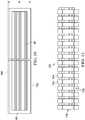
Figure 10 is an illustration of a plan view of a ply carrier having a ply mounted thereon. -
Figure 11 is an illustration of a front view of a nosepiece track forming part of each of the fabrication modules shown inFigures 7-9 . -
Figure 12 is an illustration of a perspective view of a portion of the length of a nosepiece adapted to be mounted on the nosepiece track shown inFigure 11 . -
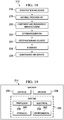
Figure 13 is an illustration of a flow diagram of a method of fabricating each of a plurality of different parts in a family of parts having common features. -
Figure 14 is an illustration of a flow diagram of a method of fabricating a composite laminate structure. -
Figure 15 is an illustration of a flow diagram of the method used to set up and teach each of the fabrication modules. -
Figure 16 is an end view of the tool shown inFigure 5 , illustrating the progressive movement of the nosepiece during the set up and teaching phase shown inFigure 15 . -
Figure 17 is illustration of a flow diagram of an adaptive control method employed by each of the fabrication modules -
Figure 18 is an illustration of a flow diagram of aircraft production and service methodology. -
Figure 19 is illustration of a block diagram of an aircraft. - Referring first to
Figure 1 , asystem 38 is provided for fabricating any of a plurality ofunique parts 54 within afamily 56 ofparts 54 having common features or characteristics. Theunique parts 54 may be fabricated using corresponding,unique tools 48, which may be layup tools, and acombination 43 offabrication modules 42 arranged and configured to form afabricator 40, sometimes hereinafter also referred to as a former 40. As will be discussed below in more detail, thefabrication modules 42 may be identical and interchangeable. The number and arrangement of thefabrication modules 42 is matched to theparticular tool 48 required to fabricate aparticular part 54. Thefabricator 40 fabricates thepart 54 by placing and formingmaterial 46 on theparticular tool 48. In one application, thepart 54 may be a multi-ply composite laminate, and thematerial 46 may be a carbon fiber reinforced plastic (CFRP). - Attention is now directed to
Figure 2 which illustrates one embodiment of thesystem 38 shown inFigure 1 . In this example, a plurality offormer modules 42 are arranged in a configuration generally matching the shape of alayup tool 48 on which a particular part (not shown inFigure 2 ) is to be formed. In the illustrated example, theformer modules 42 are arranged in an arc shape that substantially matches the arc shapedlayup tool 48, however, a variety of other shapes are possible. The former 40 forms and laminates composite plies 46 on thetool 48. Theformer modules 42 are rigidly connected with each other bylinkage 44 to form a former 40. The former 40 self-adapts and aligns itself to eachparticular tool 48 required to make a particular part 54 (Figure 1 ). Theformer modules 42 may be substantially identical to each other and are thus interchangeable 50 withmodules 42a purposes of repair, replacement or reconfiguration of the former 40 to form unique parts within a family of parts having common features or characteristics. Each of theformer modules 42 is coupled with acentral controller 52 which may comprise a special or general purpose computer, or a PLC (programmable logic controller). Thecentral controller 52 controls and coordinates the automated operation of theformer modules 42. - As previously mentioned, the former 40 may be used to form a variety of composite parts within a family of parts having common features or characteristics. For example, referring to
Figures 3 and 4 , the former 40 may be used to form and laminate acomposite frame section 58 used in an aircraft fuselage (not shown). Theframe section 58 is curved or contoured along its length and has a radius "R". The former 40 may be used to form any of a range offrame sections 58 having different arc lengths, radii or other common features within a family offrame sections 58. These features, including contours or radii, may be continuous or non-continuous along the length of theframe section 58 or other parts being formed. Theframe section 58 is generally Z-shaped in cross section, and comprises aninner chord flange 62 and an outer chord flange 64 (sometimes also referred to as a shear tie 64). The inner andouter chord flanges central web 60. Theshear tie 64 is connected to theweb 60 by ashear tie radius 68, and theinner chord flange 62 is connected to theweb 60 by aninner chord radius 70. While a Z-shapedframe section 58 has been illustrated in the exemplary embodiment, it should be noted that the disclosed method and apparatus may be employed to fabricate composite laminate parts having a variety of other cross-sectional shapes, including but not limited to L, I and C cross-sectional shapes. - Referring now to
Figure 5 , the former 40 forms and laminates composite prepreg plies 46 on atool 48. Thetool 48 has tool features matching theframe section 58. In this example, thetool 48 includes an innerchord tool flange 72, an innerchord tool radius 74, atool web 76, sheartie tool radius 78 and an outerchord tool flange 80. Thetool 48 also includes a clampingflange 82 extending around its entire inner chord. Other types oflayup tools 48 may be used in connection with the disclosed method and apparatus to form other types and sizes composite laminate parts, having cross-sectional shapes other than Z cross-sections. Moreover, the illustratedtool 48 may be employed to layup a curved composite laminate frame section or other part having an L-shaped cross-section. - Attention is now directed to
Figures 6-9 which illustrate one embodiment of the former 40.Figure 6 is a functional block diagram showing one of theformer modules 42, in the process of laying up asingle prepreg ply 46 on thetool 48. Theply 46 is supported in a desired, or indexed position on aply carrier 84 discussed below in more detail. Theply carrier 84 is held along its upper edge on acarrier track 120 at the end of asupport arm 95 forming part of theformer module 42. Theformer module 42 broadly comprises a plycarrier control assembly 86 mounted on ahead section 92 which is supported on amovable base 106. The base 106 may include an on-board controller 110 that is coupled with the central controller 52 (Figure 2 ) previously discussed. Wheels orcasters 112 on the base 106 allow theformer module 42 to be moved along a supporting surface such as a factory floor (not shown) in any direction in order to allow theformer module 42 to be positioned in a desired configuration with otherformer modules 42, such that the collective geometry of theformer modules 42 substantially matches that of thetool 48. Thebase 106 includes a Z-axis slide assembly 108 which moves thehead section 92 and the plycarrier control assembly 86 in the vertical direction, or Z-axis within a machine coordinatesystem 124. - The ply
carrier control assembly 86 controls the attitude of, and tension on theply carrier 84 in order to support and continuously reposition position theply 46 as it is being formed onto thetool 48. The plycarrier control assembly 86 may include a motorized drive system which moves thesupport arm 95 and thus thecarrier support track 120 along both the Y and Z axes. For example, the motorized drive system may comprise a servo-motor 88 for driving thecarrier support track 120 along the Y axis, and anair cylinder 90 for driving thesupport arm 95 and thecarrier support track 120 along the Z axis. Other drive arrangements are possible. - The
head section 92 includes a ply forming member, referred to hereinafter as anosepiece 116, which engages theply carrier 84 and follows the shape of thetool 48 to form and compact theply 46 onto thetool 48. Thenosepiece 116 is removably mounted in anosepiece track 118 discussed later in more detail. Thenosepiece 116 extends continuously along the entire arc length of thetool 48, and effectively forms a spline between the formingmodules 42. Both thenosepiece 116 and thetrack 118 may be flexible along their length to conform to the curvature and other features of thetool 48. Thenosepiece track 118 is coupled with a motorized drive system which may comprise, for example and without limitation, a plurality ofair cylinders 102 which move thenosepiece 116 in the Y direction. - Movement of the
nosepiece 116 in the Z direction may be effected through movement of thehead section 92 by the Z-axis slide assembly 108 on thebase 106. Thehead section 92 further includes aninner chord clamp 122 driven in the Y direction byair cylinders 104 or similar motor drives. Theinner chord clamp 122 clamps the lower edge of theply carrier 84 and theply 46 against the inner chord tool flange 72 (Figure 5 ) while theply 46 is being formed over other surfaces of thetool 48. Thehead section 92 may include adatum locator 98 which may comprise, for example and without limitation, a proximity sensor, as well as servo-motors 94 andencoders 96. The servo-motors 94 and theencoders 96 may be used to determine the position of thenosepiece 116, and thus the location of surfaces on thetool 48, during an adaptive tool learning process discussed below. One ormore load cells 100 on thehead section 92 may be used to sense the amount of force being applied by thenosepiece 116 during both the learning and ply forming processes. - As can be appreciated from the foregoing description, the former 40 provides 2-axis (Y-Z) controlled sweeping of prepreg plies with 2-axis coordinated motion. However, motion is not limited to 2 axes. For example, the required motion may be accomplished using multiple robots (not shown) operating in unison. The adaptive control employed by former 40 allows the former 42 to adapt to each
particular tool 48 used to make any of a number of parts within a family of parts, by using a generic profile of the parts in the family, and force feedback to learn and follow the specific tool and part geometry. The adaptive control used by the former 40 also automatically adapts or adjusts to the shape of thepart 54 as the thickness of thepart 54 increases with layup of eachsuccessive ply 46. The use of a combination of position control and motor torque feedback allow constant pressure to be applied by thenosepiece 116 to thepart 54 during the forming process. - As shown in
Figure 7 , thetool 48 may be supported on awheeled cart 126 for movement into proximity with a former 40 comprising a plurality offormer modules 42 that have been configured to substantially match the geometry of thetool 48. Theformer modules 42 are rigidly connected together by mechanical linkages 44 (seeFigure 8 ) betweenbases 106 of adjacentformer modules 42. Referring particularly toFigure 9 , the ply carrier control assembly 86 (Figure 6 ) includes a Z-axis slide support allowing movement of the support arm 95 (seeFigures 6-8 ) along the Z axis, and aslide 130 providing movement of thesupport arm 95 along the Y-axis. Tool clamps 114 driven byair cylinders 136 function to clamp the flange 82 (Figure 5 ) of thetool 48 against anindex plate 132 which establishes a common "waterline" or reference datum, for all of theformer modules 42, automatically aligning all of theformer modules 42 relative to thetool 48. Each of theformer modules 42 includes a slight amount of "float" that allows each of thehead sections 92 to align to the tool waterline and then lock into position. As a result of this feature, thetool 48 does not have to be located on a precise platform, and the forming process can be carried out on standard factory floors that may be uneven. Although not shown in the drawings, thetool 48 and/or theplies 46 may be heated during a layup process in order to soften the resin and facilitate forming. Heating may be achieved using any suitable technique, including but not limited to infrared radiation using IR heat lamps. - Referring to
Figure 10 , theply carrier 84 may be formed of a flexible, durable material that may be stretchable in one or more directions, for example along its width "W". One ormore plies 46 may be placed in preselected, indexed positions on theply carrier 84 prior to theply carrier 84 being loaded onto the former 40. Theply carrier 84 may include upper and lower carrier guides 140, 142 that are used to removably mount the ply carrier on the former 40. For example, theupper carrier guide 140 may include individual guide members (not shown) on the back of theply carrier 84 which are received within a groove (not shown) in thecarrier support track 120. Similarly, thelower carrier guide 142 may comprise a continuous guide strip (not shown) on the back of theply carrier 84 which is received within a groove (not shown) extending along theinner chord clamp 122. -
Figure 11 illustrates further details of one embodiment of thenosepiece track 120. In this example, thenosepiece track 120 comprises a plurality of spaced apartsegments 144 which allow thetrack 120 to flex as required to permit thenosepiece 116 to conform to features of thetool 48. As shown inFigure 12 , thenosepiece 116 includes an outer formingtip 146 that has a profile suited for the particular application and features of thetool 48. Thenosepiece 116 is mounted on thenosepiece track 120 by a T-shapedguide 148 that is slidably received within agroove 145 in thenosepiece track 120. Thenosepiece 116 may be removably installed in thenosepiece track 120 by sliding it lengthwise through thegroove 145. Thus,nosepieces 116 having different sizes and shapes are interchangeable, allowing selection of anosepiece 116 that is suitable for the application and tool shape. Thenosepiece 116 may be compliant in order to better conform it to features of thetool 48 during the forming process. -
Figure 13 broadly illustrates the steps of a method of fabricating each of the plurality ofdiffering parts 54 in afamily 56 ofparts 54 having common features, wherein each of theparts 54 is fabricated using aunique tool 48. Beginning at 154,identical fabrication modules 42 are arranged to match atool 48 in which thepart 54 to be fabricated. At 156, each of thefabrication modules 42 is adapted to a local section of thetool 48. At 158, operation of thefabrication modules 42 is controlled and coordinated to fabricate portions of thepart 54 over a corresponding section of thetool 48. -
Figure 14 broadly illustrates the steps of a method of fabricating acomposite laminate structure 54. Beginning at 160, a plurality of formingmodules 42 are arranged to match atool 48 on which thestructure 54 is to be formed. At 162, 40 themodules 42 are linked together to form a single former 40 for forming the entirecomposite laminate structure 54. At 164, a continuous formingmember 116 is mounted on the formingmodules 42. The formingmember 116 defines a spline extending substantially the entire length of the former 40. At 166, the formingmember 116 is used to form and compact composite plies 46 on thetool 48. - Attention is now directed to
Figure 15 which broadly illustrates the steps that may be carried out to set up and teach each of the formingmodules 42 in preparation for a forming process using aparticular tool 48. At 168, former 40 is set up by arranging and linkingformer modules 42 together usinglinkages 44, and initializing settings of each of themodules 42. Then, at 170, the linkedformer modules 42 are moved to engage and lock onto thetool 48. The tool clamps 114 (Figure 9 ) clamp the flange 82 (Figure 5 ) of thetool 48 against the toolwaterline index plate 132. Theformer modules 42 are aligned to match the curvature of thetool 48, and thelinkage 44 maintains the shape and alignment of theformer modules 42. At 172, theformer module 42 is taught the position of the inner chord clamp relative to thetool 48, and at 174 the position of the nosepiece relative to thetool 48 is learned. At 176, the servo-motors 94 (Figure 6 ) and theencoders 96 are used to initially learn the shape of the tool, and then to relearn the surface of the laminated plies 46 as each of theplies 46 is laid up. - Attention is now directed to
Figures 16 and17 which illustrate additional details of the disclosed forming method. Beginning at 178 (Figure 17 ), thetool 48 is moved into proximity to the former 40, and at 180, thetool 48 is clamped to the former 40. At 182, one ormore plies 46 are mounted on theply carrier 84. At 184, theply carrier 84 having theply 46 mounted thereon is loaded onto the former 40. This loading process is performed by inserting thebottom carrier guide 142 into the former at 186, and atstep 188, inserting thetop guide 140 into the upperguide rail track 120 on the former 40. At 190, the position of thenosepiece 116 along the Y-axis is determined by driving thenosepiece 116 forward along the Y-axis into contact with theinner chord flange 72 using a predetermined motor torque. Anencoder 96 coupled with the servo-motor 94 is read to indicate the position of thenosepiece 116. At 192, thenosepiece 116 is pressed against the inner chord flange with a predetermined amount of force. At 194, thenosepiece 116 is moved upwardly along the Z-axis at a predetermined rate. Theply 46 is swept and compacted against the innerchord tool surface 72, atstep 194. - At 196, the transition of the
nosepiece 116 from the innerchord tool surface 72 to theweb tool surface 76 is sensed by monitoring a Y-axis encoder 96 for a change. At 198 control of thenosepiece 116 along the Y-axis is switched from a torque mode to a position mode, and along the Z-axis from a position mode to a torque mode. Thenosepiece 116 maintains compaction pressure against theply 46 during the transition over theinside corner 74 of the inner chord to web radius. At 200, thenosepiece 116 sweeps and compacts the ply against theweb tool surface 76 on thetool 48. At 202, movement of thenosepiece 116 is terminated when thenosepiece 116 is a short distance from theshear tie radius 78. At 204, thenosepiece 116 is used to "discover" the shape of theshear tie radius 78. This is accomplished by advancing thenosepiece 116 along the Y-axis until a preselected torque limit is reached. Atstep 206, control of thenosepiece 116 is switched to the torque mode along the Y-axis and along the Z-axis. At 208, thenosepiece 116 sweeps and compacts apply against the sheartie tool surface 80. During this step, thenosepiece 116 applies force along the Y-axis in the torque mode, while being driven upwardly along the Z-axis in the position mode. Atstep 210 the ply forming process is complete and steps 182-208 may be repeated to layup, form and compact additional plies. - Embodiments of the disclosure may find use in a variety of potential applications, particularly in the transportation industry, including for example, aerospace, marine, automotive applications and other application requiring automated fabrication of a variety of parts within a family of parts having common features or characteristics. Thus, referring now to
Figures 19 and 20, embodiments of the disclosure may be used in the context of an aircraft manufacturing andservice method 212 as shown inFigure 19 and anaircraft 214 as shown in Figure 20. Aircraft applications of the disclosed embodiments may include, for example, without limitation, fuselage frame sections, spars, stringers and other structural members, to name only a few. During pre-production,exemplary method 212 may include specification anddesign 216 of theaircraft 214 andmaterial procurement 218. During production, component andsubassembly manufacturing 220 andsystem integration 222 of theaircraft 214 takes place. Thereafter, theaircraft 214 may go through certification anddelivery 224 in order to be placed inservice 226. While in service by a customer, theaircraft 214 is scheduled for routine maintenance andservice 228, which may also include modification, reconfiguration, refurbishment, and so on. - Each of the processes of
method 212 may be performed or carried out by a system integrator, a third party, and/or an operator (e.g., a customer). For the purposes of this description, a system integrator may include without limitation any number of aircraft manufacturers and major-system subcontractors; a third party may include without limitation any number of vendors, subcontractors, and suppliers; and an operator may be an airline, leasing company, military entity, service organization, and so on. - As shown in Figure 20, the
aircraft 214 produced byexemplary method 212 may include anairframe 230 with a plurality ofsystems 232 and an interior 234. Examples of high-level systems 232 include one or more of apropulsion system 236, anelectrical system 238, ahydraulic system 240, and anenvironmental system 242. Any number of other systems may be included. Although an aerospace example is shown, the principles of the disclosure may be applied to other industries, such as the marine and automotive industries. - Systems and methods embodied herein may be employed during any one or more of the stages of the production and
service method 212. For example, components or subassemblies corresponding toproduction process 220 may be fabricated or manufactured in a manner similar to components or subassemblies produced while theaircraft 214 is in service. Also, one or more apparatus embodiments, method embodiments, or a combination thereof may be utilized during the production stages 220 and 222, for example, by substantially expediting assembly of or reducing the cost of anaircraft 214. Similarly, one or more of apparatus embodiments, method embodiments, or a combination thereof may be utilized while theaircraft 242 is in service, for example and without limitation, to maintenance andservice 228. - The description of the different illustrative embodiments has been presented for purposes of illustration and description, and is not intended to be exhaustive or limited to the embodiments in the form disclosed. Many modifications and variations will be apparent to those of ordinary skill in the art. Further, different illustrative embodiments may provide different advantages as compared to other illustrative embodiments. The embodiment or embodiments selected are chosen and described in order to best explain the principles of the embodiments, the practical application, and to enable others of ordinary skill in the art to understand the disclosure for various embodiments with various modifications as are suited to the particular use contemplated.
- Embodiments are envisaged as set out in the following clauses:
- Clause 1: A system for fabricating a plurality of unique parts, comprising:
- a plurality of unique layup tools respectively corresponding to the plurality of parts to be fabricated; and,
- a plurality of former modules configured to be combined together to define a plurality of unique formers respectively corresponding to the plurality of parts and the plurality of layup tools,
- each of the formers being adapted for laying down material on a corresponding one of the layup tools to form a corresponding one of the parts.
- Clause 2: The system of
clause 1, wherein: the former modules are substantially identical, and
each of the plurality of unique formers is configured by coupling each of the substantially identical former modules to the corresponding unique layup tool. - Clause 3: The system of
clause 1, wherein the former modules are mounted on bases allowing the former modules to move in multiple directions. - Clause 4: The system of
clause 1, wherein former modules are rigidly linked together. - Clause 5: The system of
clause 1, wherein each of the former modules includes a forming head section adapted to form the material on a corresponding one of the layup tools. - Clause 6: The system of clause 5, wherein each of the forming head sections includes compliance.
- Clause 7: The system of clause 6, wherein the compliance is removed when the former modules are coupled to the layup tool.
- Clause 8: The system of
clause 1, wherein the part is a laminated structure. - Clause 9: The system of
clause 1, wherein the part is a carbon fiber reinforced plastic. - Clause 10: Apparatus for fabricating each of a plurality of differing laminate structures in a family of structures having common features, comprising:
- a plurality of separate fabrication modules each locally adapted to fabricate a section of the laminate structure on a corresponding tool, the fabrication modules being reconfigurable to fabricate each of the laminate structures in the family thereof; and
- a controller for controlling and coordinating automated operation of the fabrication modules.
- Clause 11: The apparatus of clause 10, further comprising:
a forming member adapted for forming laminate plies over the tool, the forming member extending along a length of the fabrication modules, the forming member being mounted on each of the fabrication modules for movement over the tool along at least two axes. - Clause 12: The apparatus of clause 11, wherein the forming member is continuous along the length of the fabrication modules.
- Clause 13: The apparatus of clause 11, wherein each of the fabrication modules includes a track in which a portion of the forming member is local mounted.
- Clause 14: The apparatus of clause 13, wherein the forming member is removably mounted in the tracks to allow interchangeability of a plurality of forming members respectively having different shapes.
- Clause 15: The apparatus of clause 11, wherein the forming member is adapted to sweep laminate plies over the tool, and includes compliance.
- Clause 16: The apparatus of clause 10, wherein each of the fabrication modules includes a clamp adapted for clamping a portion of a laminate ply against a portion of the tool.
- Clause 17: The apparatus of clause 11, wherein each of the fabrication modules includes a powered drive coupled with the forming member for sweeping the forming member over the laminate plies and compacting laminate plies on the tool.
- Clause 18: The apparatus of clause 11, further comprising:
- a flexible ply carrier adapted to hold at least one laminate ply thereon, and
- wherein each of the fabrication modules includes a pair of spaced apart tracks adapted to releasably hold the ply carrier, and a ply carrier control assembly for holding the ply carrier in tension as the forming member forms the ply over the tool.
- Clause 19: The apparatus of clause 18, wherein:
- the forming member is engageable with the ply carrier to sweep the ply carrier along with the ply thereon over the tool, and
- the ply carrier control assembly includes drives for adjusting a position of the ply carrier along two axes.
- Clause 20: The apparatus of clause 11, wherein each of the fabrication modules further includes:
- a force sensor for sensing a level of force applied to the laminate plies by the forming member, and
- a position sensor for sensing the position of the forming member.
- Clause 21: The apparatus of clause 10, wherein each of the fabrication modules includes a clamp for clamping the fabrication module to the tool.
- Clause 22: The apparatus of clause 10, further comprising:
linkage between the fabrication modules for rigidly coupling the fabrication modules together and for aligning the fabrication modules relative to the tool. - Clause 23: The apparatus of clause 10, wherein the fabrication modules are substantially identical and interchangeable with each other.
- Clause 24: The apparatus of clause 10, further comprising a central controller for controlling and coordinating the operation of the fabrication modules to collectively fabricate the laminate structure.
- Clause 25: A method of fabricating each of a plurality of differing parts in a family of parts having common features, wherein each of the parts is fabricated using a unique tool, comprising:
- arranging a plurality of separate, substantially identical fabrication modules to substantially match a tool on which one of the parts is to be fabricated;
- adapting each of the fabrication modules to a local section of the tool; and,
- controlling and coordinating operation of the fabrication modules to fabricate portions of the part over a corresponding section of the tool.
- Clause 26: The method of clause 25, wherein arranging the fabrication modules includes:
- moving each of the fabrication modules into proximity to the tool, and
- rigidly linking the fabrication modules together.
- Clause 27: The method of clause 25, further comprising:
clamping each of the fabrication modules to the tool. - Clause 28: The method of clause 25, wherein adapting the each of the fabrication modules includes learning, by each of the fabrication modules, the location of surfaces on the tool on which the part is to be fabricated.
- Clause 29: The method of clause 28, further comprising:
- sweeping materials across the surfaces of the tool using a forming member, and
- using the forming member to learn the location of the surfaces on the tool.
- Clause 30: The method of clause 29, wherein learning the location of the surfaces includes:
- sensing a position of the forming member as the forming member sweeps materials across the surfaces of the tool, and
- recording the sensed position of the forming member.
- Clause 31: The method of clause 25, wherein adapting each of the fabrication modules includes adjusting the elevation of the fabrication modules to a common waterline.
- Clause 32: The method of clause 25, further comprising:
forming a continuous spline along all of the fabrication modules. - Clause 33: The method of clause 32, wherein forming the continuous spline includes mounting a continuous forming member along substantially the entire length of the fabrication modules.
- Clause 34: The method of clause 25, wherein:
- each of the fabrication modules is a laminate ply former module for forming a local section of a ply, and
- arranging the fabrication modules includes linking the fabrication modules together to form a single laminate ply former.
- Clause 35: A method of fabricating a composite laminate structure, comprising:
- arranging a plurality of substantially identical forming modules to generally match a tool on which composite plies are to be formed to fabricate the laminate structure;
- linking the forming modules together to form a single former for forming an entire composite laminate structure;
- mounting a continuous forming member on the forming modules, the continuous forming member defining a spline extending substantially the entire length of the former; and
- using the forming member to form and compact the composite plies on the tool.
- Clause 36: The method of
clause 35, further comprising:- placing the composite plies on a ply carrier, and
- wherein using the forming member includes engaging and sweeping the ply carrier along with the plies over the tool.
- Clause 37: A forming module for forming a composite laminate part over a tool, comprising:
- a base;
- a ply carrier control assembly adapted for controlling the position of a flexible ply carrier on which composite resin plies are mounted; and
- a head section mounted on the base and adapted for automatically forming the composite resin plies from the ply carrier onto the tool.
- Clause 38: The forming module of clause 37, wherein the base is adapted to move over a supporting surface.
- Clause 39: The forming module of clause 37, further comprising a clamp for clamping the head section to the tool.
- Clause 40: The forming module of clause 37, wherein the head section includes an adaptive control for learning a profile of the tool.
- Clause 41: The forming module of clause 37, further comprising a nosepiece for engaging the ply carrier and forming the plies onto the tool, the nosepiece being mounted for movement on the head section along first and second axes.
- Clause 42: The forming module of clause 41, wherein the head section includes a load cell for sensing the magnitude of a force applied by the nosepiece to the ply carrier and the tool.
- Clause 43: The forming module of clause 41, wherein the base includes a powered slide assembly for moving the head section along a third axis substantially orthogonal to the first and second axes.
- Clause 44: The forming module of clause 41, wherein the head section includes at least one position sensor for sensing the position of the nosepiece.
- Clause 45: The forming module of clause 41, wherein the nosepiece has compliance allowing the nosepiece to conform to features of the tool.
- Clause 46: The forming module of clause 37, wherein the ply carrier control assembly includes a device for controlling tension on the flexible ply carrier.
- Clause 47: The forming module of clause 37, wherein the ply carrier control assembly is mounted on the head section.
- Clause 48: The forming module of clause 37, wherein the ply carrier control assembly includes an automatically controlled, motorized arm for supporting and displacing the ply carrier as the plies are being formed from the ply carrier onto the tool.
- Clause 49: The forming module of clause 37, wherein the head section includes a datum locator for locating a datum on the tool.
Claims (15)
- A forming module for forming a composite laminate part over a tool, comprising:a base;a ply carrier control assembly adapted for controlling the position of a flexible ply carrier on which composite resin plies are mounted; anda head section mounted on the base and adapted for automatically forming the composite resin plies from the ply carrier onto the tool.
- The forming module of claim 1, wherein the ply carrier is held along its upper edge on a carrier track at the end of a support arm forming part of the forming module.
- The forming module of claim 1 or claim 2, wherein the ply carrier is stretchable in one or more directions.
- The forming module of claim 1, wherein the base is adapted to move over a supporting surface.
- The forming module of claim 1, further comprising a clamp for clamping the head section to the tool.
- The forming module of claim 1, wherein the head section includes an adaptive control for learning a profile of the tool.
- The forming module of claim 1, further comprising a nosepiece for engaging the ply carrier and forming the plies onto the tool, the nosepiece being mounted for movement on the head section along first and second axes.
- The forming module of claim 7, wherein the head section includes a load cell for sensing the magnitude of a force applied by the nosepiece to the ply carrier and the tool.
- The forming module of claim 7, wherein the base includes a powered slide assembly for moving the head section along a third axis substantially orthogonal to the first and second axes.
- The forming module of claim 7, wherein the head section includes at least one position sensor for sensing the position of the nosepiece.
- The forming module of claim 1, wherein the ply carrier control assembly includes a device for controlling tension on the flexible ply carrier.
- The forming module of claim 1, wherein the ply carrier control assembly is mounted on the head section.
- The forming module of claim 1, wherein the ply carrier control assembly includes an automatically controlled, motorized arm for supporting and displacing the ply carrier as the plies are being formed from the ply carrier onto the tool.
- The forming module of claim 1, wherein the head section includes a datum locator for locating a datum on the tool.
- A method of fabricating a composite laminate structure, comprising:arranging a plurality of substantially identical forming modules to generally match a tool on which composite plies are to be formed to fabricate the laminate structure;linking the forming modules together to form a single former for forming an entire composite laminate structure;mounting a continuous forming member on the forming modules, the continuous forming member defining a spline extending substantially the entire length of the former; andusing the forming member to form and compact the composite plies on the tool,wherein the method further comprises:placing the composite plies on a flexible ply carrier, andwherein using the forming member includes engaging and sweeping the ply carrier along with the plies over the tool.
Applications Claiming Priority (4)
| Application Number | Priority Date | Filing Date | Title |
|---|---|---|---|
| US201361749881P | 2013-01-07 | 2013-01-07 | |
| US13/901,813 US9314974B2 (en) | 2013-01-07 | 2013-05-24 | Method and apparatus for fabricating contoured laminate structures |
| PCT/US2013/071124 WO2014107243A1 (en) | 2013-01-07 | 2013-11-21 | Method and apparatus for fabricating contoured laminate structures |
| EP13808304.3A EP2941342B1 (en) | 2013-01-07 | 2013-11-21 | Method and apparatus for fabricating contoured laminate structures |
Related Parent Applications (2)
| Application Number | Title | Priority Date | Filing Date |
|---|---|---|---|
| EP13808304.3A Division EP2941342B1 (en) | 2013-01-07 | 2013-11-21 | Method and apparatus for fabricating contoured laminate structures |
| EP13808304.3A Division-Into EP2941342B1 (en) | 2013-01-07 | 2013-11-21 | Method and apparatus for fabricating contoured laminate structures |
Publications (2)
| Publication Number | Publication Date |
|---|---|
| EP3750694A1 true EP3750694A1 (en) | 2020-12-16 |
| EP3750694B1 EP3750694B1 (en) | 2023-06-21 |
Family
ID=51060084
Family Applications (2)
| Application Number | Title | Priority Date | Filing Date |
|---|---|---|---|
| EP20187453.4A Active EP3750694B1 (en) | 2013-01-07 | 2013-11-21 | Method and apparatus for fabricating contoured laminate structures |
| EP13808304.3A Active EP2941342B1 (en) | 2013-01-07 | 2013-11-21 | Method and apparatus for fabricating contoured laminate structures |
Family Applications After (1)
| Application Number | Title | Priority Date | Filing Date |
|---|---|---|---|
| EP13808304.3A Active EP2941342B1 (en) | 2013-01-07 | 2013-11-21 | Method and apparatus for fabricating contoured laminate structures |
Country Status (8)
| Country | Link |
|---|---|
| US (3) | US9314974B2 (en) |
| EP (2) | EP3750694B1 (en) |
| JP (1) | JP6357486B2 (en) |
| CN (1) | CN104903080B (en) |
| BR (1) | BR112015016158B1 (en) |
| CA (1) | CA2897045C (en) |
| ES (1) | ES2834957T3 (en) |
| WO (1) | WO2014107243A1 (en) |
Families Citing this family (32)
| Publication number | Priority date | Publication date | Assignee | Title |
|---|---|---|---|---|
| US9314974B2 (en) | 2013-01-07 | 2016-04-19 | The Boeing Company | Method and apparatus for fabricating contoured laminate structures |
| US10828846B2 (en) | 2013-01-07 | 2020-11-10 | The Boeing Company | Method and apparatus for fabricating contoured laminate structures |
| US9505354B2 (en) | 2013-09-16 | 2016-11-29 | The Boeing Company | Carbon fiber reinforced polymer cargo beam with integrated cargo stanchions and c-splices |
| US10399284B2 (en) | 2014-05-16 | 2019-09-03 | The Boeing Company | Method and apparatus for forming contoured composite laminates |
| US9782937B1 (en) | 2014-05-16 | 2017-10-10 | The Boeing Company | Apparatus for forming contoured composite laminates |
| US9889610B2 (en) * | 2014-07-29 | 2018-02-13 | The Boeing Company | Automated ply forming and compaction using flexible roller contact |
| US9636876B2 (en) | 2014-10-29 | 2017-05-02 | The Boeing Company | Method, device and apparatus for vacuum forming composite laminates |
| GB2533567A (en) * | 2014-12-19 | 2016-06-29 | Airbus Operations Ltd | Method of forming laminar composite charge |
| US10086596B2 (en) * | 2015-03-12 | 2018-10-02 | The Boeing Company | Apparatus and method for automated layup of composite structures |
| US10800111B2 (en) | 2015-06-16 | 2020-10-13 | The Boeing Company | Composite structure fabrication systems and methods |
| US20180327071A1 (en) | 2017-05-10 | 2018-11-15 | The Boeing Company | Systems and methods for aircraft integrated composite frames |
| GB2566433A (en) * | 2017-07-13 | 2019-03-20 | Spirit Aerosystems Europe Ltd | Composite lay-up apparatus and method |
| US10703055B2 (en) * | 2017-07-14 | 2020-07-07 | The Boeing Company | Clamping system for holding a composite charge during forming over a forming mandrel |
| US10688711B2 (en) | 2017-07-14 | 2020-06-23 | The Boeing Company | Heat blanket assembly for forming a composite charge |
| US10843449B2 (en) | 2017-12-14 | 2020-11-24 | The Boeing Company | Method and apparatus for forming composite plies on contoured tool surfaces |
| US11014314B2 (en) | 2018-06-28 | 2021-05-25 | The Boeing Company | End effector for forming prepreg plies on highly contoured surfaces |
| US10994502B2 (en) | 2018-11-01 | 2021-05-04 | The Boeing Company | Lamination system and method using a plurality of static lamination heads |
| US10960615B2 (en) | 2018-11-13 | 2021-03-30 | The Boeing Company | System and method for laminating a composite laminate along a continuous loop lamination path |
| JP7199940B2 (en) * | 2018-12-03 | 2023-01-06 | 川崎重工業株式会社 | Composite aircraft part and manufacturing method thereof |
| US11401023B2 (en) | 2019-01-11 | 2022-08-02 | The Boeing Company | Aircraft cargo floor architecture and method of modifying the aircraft cargo floor architecture |
| CN113840718B (en) | 2019-06-14 | 2024-10-22 | 法孚机械加工系统股份有限公司 | Modular fiber placement head |
| US11148373B2 (en) | 2019-07-01 | 2021-10-19 | The Boeing Company | System and method for laying up a composite laminate having integrally laminated filler elements |
| US11507535B2 (en) | 2019-10-16 | 2022-11-22 | International Business Machines Corporation | Probabilistic verification of linked data |
| ES2958761T3 (en) * | 2019-11-13 | 2024-02-14 | Airbus Operations Slu | Device and method of forming a composite laminate to obtain a Z-shaped profile |
| US11260640B2 (en) | 2020-02-06 | 2022-03-01 | Fives Machining Systems, Inc. | Tape lamination machine scrap collection assembly |
| IL295847B2 (en) | 2020-02-06 | 2026-04-01 | Fives Machining Systems Inc | Tape lamination head with tape tension control system |
| US11498324B2 (en) | 2020-02-06 | 2022-11-15 | Fives Machining Systems, Inc. | Tape lamination machine cutting assembly |
| EP4046787B1 (en) * | 2020-03-31 | 2024-08-21 | Kawasaki Jukogyo Kabushiki Kaisha | Method for producing intermediate product of airplane component |
| US12049047B2 (en) | 2020-06-17 | 2024-07-30 | Mitsubishi Heavy Industries, Ltd. | Jig and composite material processing method |
| US12151831B2 (en) * | 2020-11-18 | 2024-11-26 | The Boeing Company | Fabrication of curved composite preforms for aircraft via assembly lines |
| ES3040733T3 (en) | 2020-11-18 | 2025-11-04 | Boeing Co | Fabrication of curved composite preforms for aircraft via assembly lines |
| NL2027437B1 (en) | 2021-01-26 | 2022-08-19 | Boeing Co | Fabrication of curved composite preforms for aircraft via assembly lines |
Citations (3)
| Publication number | Priority date | Publication date | Assignee | Title |
|---|---|---|---|---|
| US5352306A (en) * | 1993-05-27 | 1994-10-04 | Cincinnati Milacron Inc. | Tape laying apparatus and method |
| US20070229805A1 (en) * | 2006-03-28 | 2007-10-04 | Engelbart Roger W | Vision inspection system device and method |
| US20090130450A1 (en) * | 2007-11-17 | 2009-05-21 | The Boeing Company | Method and apparatus for placing plies on curved substrates |
Family Cites Families (24)
| Publication number | Priority date | Publication date | Assignee | Title |
|---|---|---|---|---|
| DE3003552C2 (en) | 1980-01-31 | 1982-06-24 | Messerschmitt-Bölkow-Blohm GmbH, 8000 München | Surface component, in particular for an aircraft |
| US4601775A (en) * | 1985-06-03 | 1986-07-22 | Cincinnati Milacron Inc. | Compliant presser member for composite tape laying machine |
| US6298896B1 (en) | 2000-03-28 | 2001-10-09 | Northrop Grumman Corporation | Apparatus for constructing a composite structure |
| US7206665B2 (en) | 2002-09-12 | 2007-04-17 | Composite Systems, Inc. | Precision feed end-effector composite fabric tape-laying apparatus and method |
| US7341086B2 (en) | 2004-10-29 | 2008-03-11 | The Boeing Company | Automated fabric layup system and method |
| ES2338551T3 (en) | 2004-12-06 | 2010-05-10 | Saab Ab | MANUFACTURING PROCEDURE OF A CURVED ARM OF COMPOSITE MATERIAL. |
| US8557165B2 (en) | 2008-10-25 | 2013-10-15 | The Boeing Company | Forming highly contoured composite parts |
| US8632653B2 (en) | 2005-05-03 | 2014-01-21 | The Boeing Company | Method of manufacturing curved composite structural elements |
| US7943076B1 (en) | 2005-05-03 | 2011-05-17 | The Boeing Company | Method of manufacturing curved composite structural elements |
| ES2640246T3 (en) | 2008-01-31 | 2017-11-02 | Orbital Atk, Inc. | A stiffness tool positioning device and the corresponding method |
| US9090028B2 (en) | 2008-04-17 | 2015-07-28 | The Boeing Company | Method for producing contoured composite structures and structures produced thereby |
| US8932423B2 (en) | 2008-04-17 | 2015-01-13 | The Boeing Company | Method for producing contoured composite structures and structures produced thereby |
| US8349105B2 (en) | 2008-04-17 | 2013-01-08 | The Boeing Company | Curved composite frames and method of making the same |
| US9278484B2 (en) | 2008-04-17 | 2016-03-08 | The Boeing Company | Method and apparatus for producing contoured composite structures and structures produced thereby |
| FR2942741B1 (en) | 2009-03-05 | 2014-05-16 | Mediterranee Const Ind | METHOD AND DEVICE FOR THE AUTOMATED MANUFACTURE OF AT LEAST ONE PIECE EXTENDED TO ONE OR MORE LAYERS OF COMPOSITE MATERIALS |
| US8282760B2 (en) * | 2010-06-10 | 2012-10-09 | Haworth, Inc. | Apparatus and process for wrapping and securing edge flaps of flexible cover sheet to panel structure |
| DE102010039955A1 (en) * | 2010-08-30 | 2012-03-01 | Deutsches Zentrum für Luft- und Raumfahrt e.V. | Production plant for the production of fiber composite components |
| US9387657B2 (en) | 2010-11-12 | 2016-07-12 | The Boeing Company | Method of fabricating a curved composite structure using composite prepreg tape |
| US8551380B2 (en) | 2010-11-12 | 2013-10-08 | The Boeing Company | Method of laying up prepreg plies on contoured tools using a deformable carrier film |
| JP2012146067A (en) * | 2011-01-11 | 2012-08-02 | Nippon Software Management Kk | Nucleic acid information processing apparatus and processing method thereof |
| US9314974B2 (en) * | 2013-01-07 | 2016-04-19 | The Boeing Company | Method and apparatus for fabricating contoured laminate structures |
| US10828846B2 (en) | 2013-01-07 | 2020-11-10 | The Boeing Company | Method and apparatus for fabricating contoured laminate structures |
| US20140338829A1 (en) | 2013-05-20 | 2014-11-20 | Invisible Gadget Guard, Inc. | Protective Film Installation Apparatus and Method |
| US11014314B2 (en) | 2018-06-28 | 2021-05-25 | The Boeing Company | End effector for forming prepreg plies on highly contoured surfaces |
-
2013
- 2013-05-24 US US13/901,813 patent/US9314974B2/en active Active
- 2013-11-21 WO PCT/US2013/071124 patent/WO2014107243A1/en not_active Ceased
- 2013-11-21 JP JP2015551676A patent/JP6357486B2/en active Active
- 2013-11-21 BR BR112015016158-8A patent/BR112015016158B1/en active IP Right Grant
- 2013-11-21 EP EP20187453.4A patent/EP3750694B1/en active Active
- 2013-11-21 ES ES13808304T patent/ES2834957T3/en active Active
- 2013-11-21 CA CA2897045A patent/CA2897045C/en active Active
- 2013-11-21 CN CN201380069656.2A patent/CN104903080B/en active Active
- 2013-11-21 EP EP13808304.3A patent/EP2941342B1/en active Active
-
2016
- 2016-04-01 US US15/089,399 patent/US10464265B2/en active Active
-
2019
- 2019-10-11 US US16/599,341 patent/US11534989B2/en active Active
Patent Citations (3)
| Publication number | Priority date | Publication date | Assignee | Title |
|---|---|---|---|---|
| US5352306A (en) * | 1993-05-27 | 1994-10-04 | Cincinnati Milacron Inc. | Tape laying apparatus and method |
| US20070229805A1 (en) * | 2006-03-28 | 2007-10-04 | Engelbart Roger W | Vision inspection system device and method |
| US20090130450A1 (en) * | 2007-11-17 | 2009-05-21 | The Boeing Company | Method and apparatus for placing plies on curved substrates |
Also Published As
| Publication number | Publication date |
|---|---|
| CA2897045A1 (en) | 2014-07-10 |
| US20160214330A1 (en) | 2016-07-28 |
| BR112015016158A8 (en) | 2019-10-22 |
| US11534989B2 (en) | 2022-12-27 |
| ES2834957T3 (en) | 2021-06-21 |
| EP2941342A1 (en) | 2015-11-11 |
| WO2014107243A1 (en) | 2014-07-10 |
| BR112015016158A2 (en) | 2017-07-11 |
| EP3750694B1 (en) | 2023-06-21 |
| US20200039154A1 (en) | 2020-02-06 |
| US10464265B2 (en) | 2019-11-05 |
| JP6357486B2 (en) | 2018-07-11 |
| JP2016508900A (en) | 2016-03-24 |
| CN104903080B (en) | 2018-09-07 |
| EP2941342B1 (en) | 2020-09-09 |
| US9314974B2 (en) | 2016-04-19 |
| BR112015016158B1 (en) | 2021-04-20 |
| US20140190625A1 (en) | 2014-07-10 |
| CN104903080A (en) | 2015-09-09 |
| CA2897045C (en) | 2017-08-29 |
Similar Documents
| Publication | Publication Date | Title |
|---|---|---|
| US11534989B2 (en) | Method and apparatus for fabricating contoured laminate structures | |
| US10828846B2 (en) | Method and apparatus for fabricating contoured laminate structures | |
| EP2444240B1 (en) | Composite manufacturing method using an assembly of composite modules | |
| US11807395B2 (en) | Assembly line fabrication and assembly of aircraft wings | |
| US12187457B2 (en) | Assembly line fabrication and assembly of aircraft wings | |
| JP7820126B2 (en) | Assembly line manufacturing and aircraft wing assembly | |
| JP7822750B2 (en) | Assembly line manufacturing and aircraft wing assembly | |
| EP4000899A1 (en) | Method and system for carrying a wing panel of an aircraft | |
| EP4001126A1 (en) | Assembly line fabrication and assembly of aircraft wings | |
| JP7797172B2 (en) | Assembly line manufacturing and aircraft wing assembly | |
| NL2027393B1 (en) | Assembly line fabrication and assembly of aircraft wings | |
| EP4000900A1 (en) | Method and apparatus for installing indexing features into a composite part | |
| HK1164221B (en) | Composite manufacturing method using an assembly of composite modules | |
| HK1164221A (en) | Composite manufacturing method using an assembly of composite modules |
Legal Events
| Date | Code | Title | Description |
|---|---|---|---|
| PUAI | Public reference made under article 153(3) epc to a published international application that has entered the european phase |
Free format text: ORIGINAL CODE: 0009012 |
|
| STAA | Information on the status of an ep patent application or granted ep patent |
Free format text: STATUS: THE APPLICATION HAS BEEN PUBLISHED |
|
| AC | Divisional application: reference to earlier application |
Ref document number: 2941342 Country of ref document: EP Kind code of ref document: P |
|
| AK | Designated contracting states |
Kind code of ref document: A1 Designated state(s): AL AT BE BG CH CY CZ DE DK EE ES FI FR GB GR HR HU IE IS IT LI LT LU LV MC MK MT NL NO PL PT RO RS SE SI SK SM TR |
|
| STAA | Information on the status of an ep patent application or granted ep patent |
Free format text: STATUS: REQUEST FOR EXAMINATION WAS MADE |
|
| 17P | Request for examination filed |
Effective date: 20210422 |
|
| RBV | Designated contracting states (corrected) |
Designated state(s): AL AT BE BG CH CY CZ DE DK EE ES FI FR GB GR HR HU IE IS IT LI LT LU LV MC MK MT NL NO PL PT RO RS SE SI SK SM TR |
|
| GRAP | Despatch of communication of intention to grant a patent |
Free format text: ORIGINAL CODE: EPIDOSNIGR1 |
|
| STAA | Information on the status of an ep patent application or granted ep patent |
Free format text: STATUS: GRANT OF PATENT IS INTENDED |
|
| INTG | Intention to grant announced |
Effective date: 20230103 |
|
| RIN1 | Information on inventor provided before grant (corrected) |
Inventor name: DEPASE, EDOARDO P. Inventor name: MODIN, ANDREW E. Inventor name: SANCHEZ, JESUS Inventor name: STEWART, DENNIS W. Inventor name: BANKS, DAVID P. Inventor name: BUTTRICK, JAMES N. |
|
| RAP3 | Party data changed (applicant data changed or rights of an application transferred) |
Owner name: THE BOEING COMPANY |
|
| GRAS | Grant fee paid |
Free format text: ORIGINAL CODE: EPIDOSNIGR3 |
|
| GRAA | (expected) grant |
Free format text: ORIGINAL CODE: 0009210 |
|
| STAA | Information on the status of an ep patent application or granted ep patent |
Free format text: STATUS: THE PATENT HAS BEEN GRANTED |
|
| AC | Divisional application: reference to earlier application |
Ref document number: 2941342 Country of ref document: EP Kind code of ref document: P |
|
| AK | Designated contracting states |
Kind code of ref document: B1 Designated state(s): AL AT BE BG CH CY CZ DE DK EE ES FI FR GB GR HR HU IE IS IT LI LT LU LV MC MK MT NL NO PL PT RO RS SE SI SK SM TR |
|
| REG | Reference to a national code |
Ref country code: CH Ref legal event code: EP |
|
| P01 | Opt-out of the competence of the unified patent court (upc) registered |
Effective date: 20230601 |
|
| REG | Reference to a national code |
Ref country code: DE Ref legal event code: R096 Ref document number: 602013084106 Country of ref document: DE |
|
| REG | Reference to a national code |
Ref country code: AT Ref legal event code: REF Ref document number: 1580627 Country of ref document: AT Kind code of ref document: T Effective date: 20230715 |
|
| REG | Reference to a national code |
Ref country code: IE Ref legal event code: FG4D |
|
| REG | Reference to a national code |
Ref country code: LT Ref legal event code: MG9D |
|
| REG | Reference to a national code |
Ref country code: NL Ref legal event code: MP Effective date: 20230621 |
|
| PG25 | Lapsed in a contracting state [announced via postgrant information from national office to epo] |
Ref country code: SE Free format text: LAPSE BECAUSE OF FAILURE TO SUBMIT A TRANSLATION OF THE DESCRIPTION OR TO PAY THE FEE WITHIN THE PRESCRIBED TIME-LIMIT Effective date: 20230621 Ref country code: NO Free format text: LAPSE BECAUSE OF FAILURE TO SUBMIT A TRANSLATION OF THE DESCRIPTION OR TO PAY THE FEE WITHIN THE PRESCRIBED TIME-LIMIT Effective date: 20230921 |
|
| REG | Reference to a national code |
Ref country code: AT Ref legal event code: MK05 Ref document number: 1580627 Country of ref document: AT Kind code of ref document: T Effective date: 20230621 |
|
| PG25 | Lapsed in a contracting state [announced via postgrant information from national office to epo] |
Ref country code: RS Free format text: LAPSE BECAUSE OF FAILURE TO SUBMIT A TRANSLATION OF THE DESCRIPTION OR TO PAY THE FEE WITHIN THE PRESCRIBED TIME-LIMIT Effective date: 20230621 Ref country code: NL Free format text: LAPSE BECAUSE OF FAILURE TO SUBMIT A TRANSLATION OF THE DESCRIPTION OR TO PAY THE FEE WITHIN THE PRESCRIBED TIME-LIMIT Effective date: 20230621 Ref country code: LV Free format text: LAPSE BECAUSE OF FAILURE TO SUBMIT A TRANSLATION OF THE DESCRIPTION OR TO PAY THE FEE WITHIN THE PRESCRIBED TIME-LIMIT Effective date: 20230621 Ref country code: LT Free format text: LAPSE BECAUSE OF FAILURE TO SUBMIT A TRANSLATION OF THE DESCRIPTION OR TO PAY THE FEE WITHIN THE PRESCRIBED TIME-LIMIT Effective date: 20230621 Ref country code: HR Free format text: LAPSE BECAUSE OF FAILURE TO SUBMIT A TRANSLATION OF THE DESCRIPTION OR TO PAY THE FEE WITHIN THE PRESCRIBED TIME-LIMIT Effective date: 20230621 Ref country code: GR Free format text: LAPSE BECAUSE OF FAILURE TO SUBMIT A TRANSLATION OF THE DESCRIPTION OR TO PAY THE FEE WITHIN THE PRESCRIBED TIME-LIMIT Effective date: 20230922 |
|
| PG25 | Lapsed in a contracting state [announced via postgrant information from national office to epo] |
Ref country code: FI Free format text: LAPSE BECAUSE OF FAILURE TO SUBMIT A TRANSLATION OF THE DESCRIPTION OR TO PAY THE FEE WITHIN THE PRESCRIBED TIME-LIMIT Effective date: 20230621 |
|
| PG25 | Lapsed in a contracting state [announced via postgrant information from national office to epo] |
Ref country code: SK Free format text: LAPSE BECAUSE OF FAILURE TO SUBMIT A TRANSLATION OF THE DESCRIPTION OR TO PAY THE FEE WITHIN THE PRESCRIBED TIME-LIMIT Effective date: 20230621 |
|
| PG25 | Lapsed in a contracting state [announced via postgrant information from national office to epo] |
Ref country code: ES Free format text: LAPSE BECAUSE OF FAILURE TO SUBMIT A TRANSLATION OF THE DESCRIPTION OR TO PAY THE FEE WITHIN THE PRESCRIBED TIME-LIMIT Effective date: 20230621 |
|
| PG25 | Lapsed in a contracting state [announced via postgrant information from national office to epo] |
Ref country code: IS Free format text: LAPSE BECAUSE OF FAILURE TO SUBMIT A TRANSLATION OF THE DESCRIPTION OR TO PAY THE FEE WITHIN THE PRESCRIBED TIME-LIMIT Effective date: 20231021 |
|
| PG25 | Lapsed in a contracting state [announced via postgrant information from national office to epo] |
Ref country code: SM Free format text: LAPSE BECAUSE OF FAILURE TO SUBMIT A TRANSLATION OF THE DESCRIPTION OR TO PAY THE FEE WITHIN THE PRESCRIBED TIME-LIMIT Effective date: 20230621 Ref country code: SK Free format text: LAPSE BECAUSE OF FAILURE TO SUBMIT A TRANSLATION OF THE DESCRIPTION OR TO PAY THE FEE WITHIN THE PRESCRIBED TIME-LIMIT Effective date: 20230621 Ref country code: RO Free format text: LAPSE BECAUSE OF FAILURE TO SUBMIT A TRANSLATION OF THE DESCRIPTION OR TO PAY THE FEE WITHIN THE PRESCRIBED TIME-LIMIT Effective date: 20230621 Ref country code: PT Free format text: LAPSE BECAUSE OF FAILURE TO SUBMIT A TRANSLATION OF THE DESCRIPTION OR TO PAY THE FEE WITHIN THE PRESCRIBED TIME-LIMIT Effective date: 20231023 Ref country code: IS Free format text: LAPSE BECAUSE OF FAILURE TO SUBMIT A TRANSLATION OF THE DESCRIPTION OR TO PAY THE FEE WITHIN THE PRESCRIBED TIME-LIMIT Effective date: 20231021 Ref country code: ES Free format text: LAPSE BECAUSE OF FAILURE TO SUBMIT A TRANSLATION OF THE DESCRIPTION OR TO PAY THE FEE WITHIN THE PRESCRIBED TIME-LIMIT Effective date: 20230621 Ref country code: EE Free format text: LAPSE BECAUSE OF FAILURE TO SUBMIT A TRANSLATION OF THE DESCRIPTION OR TO PAY THE FEE WITHIN THE PRESCRIBED TIME-LIMIT Effective date: 20230621 Ref country code: CZ Free format text: LAPSE BECAUSE OF FAILURE TO SUBMIT A TRANSLATION OF THE DESCRIPTION OR TO PAY THE FEE WITHIN THE PRESCRIBED TIME-LIMIT Effective date: 20230621 Ref country code: AT Free format text: LAPSE BECAUSE OF FAILURE TO SUBMIT A TRANSLATION OF THE DESCRIPTION OR TO PAY THE FEE WITHIN THE PRESCRIBED TIME-LIMIT Effective date: 20230621 |
|
| PG25 | Lapsed in a contracting state [announced via postgrant information from national office to epo] |
Ref country code: PL Free format text: LAPSE BECAUSE OF FAILURE TO SUBMIT A TRANSLATION OF THE DESCRIPTION OR TO PAY THE FEE WITHIN THE PRESCRIBED TIME-LIMIT Effective date: 20230621 |
|
| REG | Reference to a national code |
Ref country code: DE Ref legal event code: R097 Ref document number: 602013084106 Country of ref document: DE |
|
| PLBE | No opposition filed within time limit |
Free format text: ORIGINAL CODE: 0009261 |
|
| STAA | Information on the status of an ep patent application or granted ep patent |
Free format text: STATUS: NO OPPOSITION FILED WITHIN TIME LIMIT |
|
| PG25 | Lapsed in a contracting state [announced via postgrant information from national office to epo] |
Ref country code: DK Free format text: LAPSE BECAUSE OF FAILURE TO SUBMIT A TRANSLATION OF THE DESCRIPTION OR TO PAY THE FEE WITHIN THE PRESCRIBED TIME-LIMIT Effective date: 20230621 |
|
| PG25 | Lapsed in a contracting state [announced via postgrant information from national office to epo] |
Ref country code: SI Free format text: LAPSE BECAUSE OF FAILURE TO SUBMIT A TRANSLATION OF THE DESCRIPTION OR TO PAY THE FEE WITHIN THE PRESCRIBED TIME-LIMIT Effective date: 20230621 |
|
| 26N | No opposition filed |
Effective date: 20240322 |
|
| PG25 | Lapsed in a contracting state [announced via postgrant information from national office to epo] |
Ref country code: SI Free format text: LAPSE BECAUSE OF FAILURE TO SUBMIT A TRANSLATION OF THE DESCRIPTION OR TO PAY THE FEE WITHIN THE PRESCRIBED TIME-LIMIT Effective date: 20230621 Ref country code: IT Free format text: LAPSE BECAUSE OF FAILURE TO SUBMIT A TRANSLATION OF THE DESCRIPTION OR TO PAY THE FEE WITHIN THE PRESCRIBED TIME-LIMIT Effective date: 20230621 |
|
| REG | Reference to a national code |
Ref country code: CH Ref legal event code: PL |
|
| PG25 | Lapsed in a contracting state [announced via postgrant information from national office to epo] |
Ref country code: MC Free format text: LAPSE BECAUSE OF FAILURE TO SUBMIT A TRANSLATION OF THE DESCRIPTION OR TO PAY THE FEE WITHIN THE PRESCRIBED TIME-LIMIT Effective date: 20230621 |
|
| PG25 | Lapsed in a contracting state [announced via postgrant information from national office to epo] |
Ref country code: LU Free format text: LAPSE BECAUSE OF NON-PAYMENT OF DUE FEES Effective date: 20231121 |
|
| PG25 | Lapsed in a contracting state [announced via postgrant information from national office to epo] |
Ref country code: CH Free format text: LAPSE BECAUSE OF NON-PAYMENT OF DUE FEES Effective date: 20231130 |
|
| PG25 | Lapsed in a contracting state [announced via postgrant information from national office to epo] |
Ref country code: MC Free format text: LAPSE BECAUSE OF FAILURE TO SUBMIT A TRANSLATION OF THE DESCRIPTION OR TO PAY THE FEE WITHIN THE PRESCRIBED TIME-LIMIT Effective date: 20230621 Ref country code: LU Free format text: LAPSE BECAUSE OF NON-PAYMENT OF DUE FEES Effective date: 20231121 Ref country code: CH Free format text: LAPSE BECAUSE OF NON-PAYMENT OF DUE FEES Effective date: 20231130 |
|
| REG | Reference to a national code |
Ref country code: BE Ref legal event code: MM Effective date: 20231130 |
|
| REG | Reference to a national code |
Ref country code: IE Ref legal event code: MM4A |
|
| PG25 | Lapsed in a contracting state [announced via postgrant information from national office to epo] |
Ref country code: IE Free format text: LAPSE BECAUSE OF NON-PAYMENT OF DUE FEES Effective date: 20231121 |
|
| PG25 | Lapsed in a contracting state [announced via postgrant information from national office to epo] |
Ref country code: BE Free format text: LAPSE BECAUSE OF NON-PAYMENT OF DUE FEES Effective date: 20231130 |
|
| PG25 | Lapsed in a contracting state [announced via postgrant information from national office to epo] |
Ref country code: IE Free format text: LAPSE BECAUSE OF NON-PAYMENT OF DUE FEES Effective date: 20231121 Ref country code: BE Free format text: LAPSE BECAUSE OF NON-PAYMENT OF DUE FEES Effective date: 20231130 |
|
| PG25 | Lapsed in a contracting state [announced via postgrant information from national office to epo] |
Ref country code: BG Free format text: LAPSE BECAUSE OF FAILURE TO SUBMIT A TRANSLATION OF THE DESCRIPTION OR TO PAY THE FEE WITHIN THE PRESCRIBED TIME-LIMIT Effective date: 20230621 |
|
| PG25 | Lapsed in a contracting state [announced via postgrant information from national office to epo] |
Ref country code: BG Free format text: LAPSE BECAUSE OF FAILURE TO SUBMIT A TRANSLATION OF THE DESCRIPTION OR TO PAY THE FEE WITHIN THE PRESCRIBED TIME-LIMIT Effective date: 20230621 |
|
| PG25 | Lapsed in a contracting state [announced via postgrant information from national office to epo] |
Ref country code: CY Free format text: LAPSE BECAUSE OF FAILURE TO SUBMIT A TRANSLATION OF THE DESCRIPTION OR TO PAY THE FEE WITHIN THE PRESCRIBED TIME-LIMIT; INVALID AB INITIO Effective date: 20131121 |
|
| PG25 | Lapsed in a contracting state [announced via postgrant information from national office to epo] |
Ref country code: HU Free format text: LAPSE BECAUSE OF FAILURE TO SUBMIT A TRANSLATION OF THE DESCRIPTION OR TO PAY THE FEE WITHIN THE PRESCRIBED TIME-LIMIT; INVALID AB INITIO Effective date: 20131121 |
|
| PG25 | Lapsed in a contracting state [announced via postgrant information from national office to epo] |
Ref country code: TR Free format text: LAPSE BECAUSE OF FAILURE TO SUBMIT A TRANSLATION OF THE DESCRIPTION OR TO PAY THE FEE WITHIN THE PRESCRIBED TIME-LIMIT Effective date: 20230621 |
|
| PGFP | Annual fee paid to national office [announced via postgrant information from national office to epo] |
Ref country code: DE Payment date: 20251128 Year of fee payment: 13 |
|
| PGFP | Annual fee paid to national office [announced via postgrant information from national office to epo] |
Ref country code: GB Payment date: 20251127 Year of fee payment: 13 |
|
| PGFP | Annual fee paid to national office [announced via postgrant information from national office to epo] |
Ref country code: FR Payment date: 20251125 Year of fee payment: 13 |