EP3750454A1 - Bag storage case - Google Patents
Bag storage case Download PDFInfo
- Publication number
- EP3750454A1 EP3750454A1 EP20169579.8A EP20169579A EP3750454A1 EP 3750454 A1 EP3750454 A1 EP 3750454A1 EP 20169579 A EP20169579 A EP 20169579A EP 3750454 A1 EP3750454 A1 EP 3750454A1
- Authority
- EP
- European Patent Office
- Prior art keywords
- take
- stacked
- out opening
- width
- bags
- Prior art date
- Legal status (The legal status is an assumption and is not a legal conclusion. Google has not performed a legal analysis and makes no representation as to the accuracy of the status listed.)
- Granted
Links
Images



Classifications
-
- A—HUMAN NECESSITIES
- A47—FURNITURE; DOMESTIC ARTICLES OR APPLIANCES; COFFEE MILLS; SPICE MILLS; SUCTION CLEANERS IN GENERAL
- A47F—SPECIAL FURNITURE, FITTINGS, OR ACCESSORIES FOR SHOPS, STOREHOUSES, BARS, RESTAURANTS OR THE LIKE; PAYING COUNTERS
- A47F9/00—Shop, bar, bank or like counters
- A47F9/02—Paying counters
- A47F9/04—Check-out counters, e.g. for self-service stores
- A47F9/042—Shopping bags or carton-dispensing systems therefor
-
- B—PERFORMING OPERATIONS; TRANSPORTING
- B65—CONVEYING; PACKING; STORING; HANDLING THIN OR FILAMENTARY MATERIAL
- B65D—CONTAINERS FOR STORAGE OR TRANSPORT OF ARTICLES OR MATERIALS, e.g. BAGS, BARRELS, BOTTLES, BOXES, CANS, CARTONS, CRATES, DRUMS, JARS, TANKS, HOPPERS, FORWARDING CONTAINERS; ACCESSORIES, CLOSURES, OR FITTINGS THEREFOR; PACKAGING ELEMENTS; PACKAGES
- B65D83/00—Containers or packages with special means for dispensing contents
- B65D83/08—Containers or packages with special means for dispensing contents for dispensing thin flat articles in succession
- B65D83/0805—Containers or packages with special means for dispensing contents for dispensing thin flat articles in succession through an aperture in a wall
- B65D83/0811—Containers or packages with special means for dispensing contents for dispensing thin flat articles in succession through an aperture in a wall with means for assisting dispensing
- B65D83/0817—Containers or packages with special means for dispensing contents for dispensing thin flat articles in succession through an aperture in a wall with means for assisting dispensing the articles being automatically urged towards the dispensing aperture, e.g. spring-loaded
-
- B—PERFORMING OPERATIONS; TRANSPORTING
- B65—CONVEYING; PACKING; STORING; HANDLING THIN OR FILAMENTARY MATERIAL
- B65D—CONTAINERS FOR STORAGE OR TRANSPORT OF ARTICLES OR MATERIALS, e.g. BAGS, BARRELS, BOTTLES, BOXES, CANS, CARTONS, CRATES, DRUMS, JARS, TANKS, HOPPERS, FORWARDING CONTAINERS; ACCESSORIES, CLOSURES, OR FITTINGS THEREFOR; PACKAGING ELEMENTS; PACKAGES
- B65D25/00—Details of other kinds or types of rigid or semi-rigid containers
- B65D25/02—Internal fittings
-
- B—PERFORMING OPERATIONS; TRANSPORTING
- B65—CONVEYING; PACKING; STORING; HANDLING THIN OR FILAMENTARY MATERIAL
- B65D—CONTAINERS FOR STORAGE OR TRANSPORT OF ARTICLES OR MATERIALS, e.g. BAGS, BARRELS, BOTTLES, BOXES, CANS, CARTONS, CRATES, DRUMS, JARS, TANKS, HOPPERS, FORWARDING CONTAINERS; ACCESSORIES, CLOSURES, OR FITTINGS THEREFOR; PACKAGING ELEMENTS; PACKAGES
- B65D25/00—Details of other kinds or types of rigid or semi-rigid containers
- B65D25/38—Devices for discharging contents
- B65D25/52—Devices for discharging successive articles or portions of contents
-
- B—PERFORMING OPERATIONS; TRANSPORTING
- B65—CONVEYING; PACKING; STORING; HANDLING THIN OR FILAMENTARY MATERIAL
- B65D—CONTAINERS FOR STORAGE OR TRANSPORT OF ARTICLES OR MATERIALS, e.g. BAGS, BARRELS, BOTTLES, BOXES, CANS, CARTONS, CRATES, DRUMS, JARS, TANKS, HOPPERS, FORWARDING CONTAINERS; ACCESSORIES, CLOSURES, OR FITTINGS THEREFOR; PACKAGING ELEMENTS; PACKAGES
- B65D33/00—Details of, or accessories for, sacks or bags
- B65D33/001—Blocks, stacks or like assemblies of bags
-
- B—PERFORMING OPERATIONS; TRANSPORTING
- B65—CONVEYING; PACKING; STORING; HANDLING THIN OR FILAMENTARY MATERIAL
- B65D—CONTAINERS FOR STORAGE OR TRANSPORT OF ARTICLES OR MATERIALS, e.g. BAGS, BARRELS, BOTTLES, BOXES, CANS, CARTONS, CRATES, DRUMS, JARS, TANKS, HOPPERS, FORWARDING CONTAINERS; ACCESSORIES, CLOSURES, OR FITTINGS THEREFOR; PACKAGING ELEMENTS; PACKAGES
- B65D83/00—Containers or packages with special means for dispensing contents
- B65D83/08—Containers or packages with special means for dispensing contents for dispensing thin flat articles in succession
- B65D83/0805—Containers or packages with special means for dispensing contents for dispensing thin flat articles in succession through an aperture in a wall
Definitions
- Embodiments described herein relate to a bag storage case.
- the self-checkout device is a device for reading information of a commodity by the customer himself/herself to perform settlement.
- the settlement apparatus is an apparatus for allowing the customer to perform only the settlement.
- the commodity which has been subjected to the settlement processing by using such a settlement apparatus is placed into the bag by the customer.
- Such a bag is called a register bag, and for example, a clerk who is in charge provides the register bag to the customer.
- One of the objects of the present invention is to improve prior art techniques and overcome at least some of the prior art problems as for instance above illustrated.
- a bag storage case comprising: a holding part for holding a plurality of stacked bags; a wall having a take-out opening, the take-out opening extending in a width direction of the plurality of stacked bags and having a first width in the width direction that is smaller than a second width of the plurality of stacked bags and a middle of the take-out opening is larger than opposing ends of the take-out opening in a stacking direction of the plurality of stacked bags.
- the wall, side walls on either side of the wall, an upper wall on an upper side of the wall, and a bottom wall on a bottom side of the wall form a partially enclosed holding area for the plurality of stacked bags.
- the plurality of stacked bags when held by the holding part, the plurality of stacked bags are folded, and the take-out opening faces a folded portion of the plurality of stacked and folded bags held by the holding part.
- the bag storage case according to the first aspect of the present invention further comprises an adjusting member configured to adjust a position of the plurality of stacked bags held by the holding part with respect to the take-out opening.
- a bag storage case comprising: a housing including a pair of first walls, a pair of second walls, and a third wall, the pair of first walls and the pair of second walls forming a parallelepiped shape and the third wall covering one of two openings formed by the pair of first walls and the pair of second walls, the third wall having a take-out opening extending in a fist direction and having a first width, the take-out opening having a middle portion that is larger than opposite end portions of the take-out opening; and a holder configured to hold a plurality of stacked and folded bags, the plurality of stacked and folded bags having a second width that is larger than the first width of the take-out opening, the holder being insertable into the housing through an opening opposite the third wall so that a folded portion of the plurality of stacked and folded bags is opposite the take-out opening.
- the third wall comprises a first inclined part and a second inclined part, the take-out opening being formed in the first inclined part.
- the holder comprises a tray and a holding part, the holding part including a shaft that is configured to be received in the folded portion of the plurality of stacked and folded bags.
- the holding part includes a support plate configured to support a first side of the plurality of stacked and folded bags.
- the support plate is at an angle to the pair of first walls when the holder is inserted into the housing.
- the holding part includes an adjusting member configured to bias the folded portion toward the take-out opening.
- the tray includes a hanging part configured to a second side of the plurality of stacked and folded bags.
- the hanging part includes a cylindrical part and a flange at an end of the cylindrical part, the cylindrical part being configured to inserted into a hole in the plurality of stacked and folded bags, and the flange having a diameter larger than a diameter of the hole.
- the holder further comprises a guide part comprising a pair of projections that are configured to engage opposing sides of a bag from the plurality of stacked and folded bags being withdrawn through the take-out opening.
- the first width of the take-out opening is a function of the second width of the plurality of stacked and folded bags.
- the function is a linear function.
- the opposite end portion of the take-out opening are curved.
- a bag storage system comprising: a plurality of bag storage cases according to second aspect of the invention.
- At least one take-out opening of the plurality of bag storage cases has a different first width from at least one other bag storage case.
- the bag storage case includes a holding part and a wall.
- the holding part holds a plurality of stacked bags.
- the wall has a take-out opening, the take-out opening extends in a width direction of the plurality of stacked bags and has a first width in the width direction that is smaller than a second width of the plurality of stacked bags and a middle of the take-out opening is larger than opposite ends of the take-out opening in a stacking direction of the plurality of stacked bags.
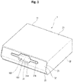
- FIG. 1 is a perspective view showing the configuration of the bag storage case 1 according to the first embodiment from the front side.
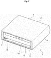
- FIG. 2 is a perspective view showing the configuration of the bag storage case 1 from the back side.
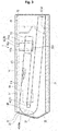
- FIG. 3 is a sectional view showing the configuration of the bag storage case 1.
- FIG. 4 is a perspective view showing bag storage cases 1 that are stacked.
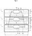
- FIG. 5 is a front view showing bag storage cases 1 that are stacked.
- FIG. 6 is a view showing the structure of the bag storage case 1 from the front side.
- FIG. 7 is a view showing a relationship between the width Tw of the take-out opening 31 of the bag storage case 1 and the width Fs of the bag 100.
- the bag storage case 1 includes a housing 11 and a holder 12.
- the bag storage case 1 accommodates a plurality of bags 100 in the housing 11 in a state in which the plurality of bags 100 are stacked and held by the holder 12.
- the plurality of bags 100 are held so as to be able to be taken out in the state in which the plurality of bags 100 are stacked by the holder 12.
- the bag storage case 1 is formed so as to be stackable with additional storage cases.
- the bag 100 is a so-called "register bag".
- the bag 100 includes a main part 111, a pair of handles 112, and a hung part 113. One end of the main part 111 is closed, and the other end is open. The closed end of the main part 111 forms the bottom of the bag 100. The extending direction of the closed end edge forming the bottom of the bag 100 will be described below with reference to the width direction of the bag 100.
- the pair of handles 112 are integrally formed on the other end of the main part 111 on an opening of the main part 111 of the bag 100.
- the hung part 113 is provided at one end of the opening of the main part 111 and between the pair of handles 112.
- the hung part 113 is formed, for example, with a hole 113a.
- the hung part 113 is integrally provided with the main part 111 so as to be separable from the main part 111.
- a perforation or the like is formed at the boundary between the main part 111 and the hung part 113 to separate the hung part 113 from the main part 111.
- a plurality of bags having different widths are used as the bags 100.
- three types of bags 100 having an L-size having a large width, an M-size having a middle width size, and an S-size having a small width are used.
- the L-size bag 100 has a width of 320mm
- the M-size bag 100 has a width of 260mm
- the S-size bag 100 has a width of 145mm.
- a plurality of such bags 100 are stacked and folded at a folded portion 150 in the main part 111. Then the folded portion 150 is held on a shaft 51 in the holder 12, and the plurality of stacked and folded bags 100 are accommodated in the housing 11.
- the housing 11 includes a pair of first walls 21, a pair of second walls 22, and a third wall 23.
- the housing 11 is formed in a rectangular box shape in which one surface is opened by, for example, a pair of first walls 21, a pair of second walls 22, and a third wall 23.
- the pair of first walls 21 are opposed to each other at intervals in which a plurality of stacked and folded bags 100 are disposed. That is, the pair of first walls 21 are opposed to each other so as to accommodate a plurality of stacked and folded bags 100. More specifically, the pair of first walls 21 are spaced apart from each other at intervals in which the holder 12 for holding the stacked and folded bags 100 can be disposed.
- the pair of first walls 21 are opposed to the stacked and folded bags 100 in the stacking direction of the plurality of stacked and folded bags 100.
- the pair of first walls 21 are opposed to the main surface of the main part 111 of the bag 100.
- the bag storage case 1 is placed on an installation surface such that one of the pair of first walls 21 is positioned downward.
- the pair of first walls 21 are opposed to each other in the height direction to form a bottom wall and a top wall of the bag storage case 1.
- the pair of second walls 22 are continuous with the pair of first walls 21.
- the pair of second walls 22 are opposed to each other in the width direction of the accommodated stacked and folded bags 100.
- the pair of second walls 22 are spaced apart from each other a distance larger than the width of the stacked and folded bags 100 so that the plurality of stacked and folded bags 100 can be disposed.
- the pair of second walls 22 constitute a pair of side walls of the bag storage case 1.
- the third wall 23 has a take-out opening 31 in a part thereof.
- the third wall 23 is continuous with the pair of first walls 21 and the pair of second walls 22.
- the third wall 23 includes, for example, a first inclined part 32 inclined to the opposing direction of the pair of first walls 21, and a second inclined part 33 inclined with respect to the opposing direction of the pair of first walls 21 and inclined in a direction different from the direction of the first inclined part 32.
- the "opposite direction of the pair of first walls 21" will be described as the "first direction”.
- the first direction is the lateral, or vertical, direction.
- the take-out opening 31 is provided in the first inclined part 32.
- the take-out opening 31 is opposed to the folded portion 150 of the plurality of stacked and folded bags 100 accommodated in the housing 11.
- the take-out opening 31 extends along the opposite direction of the pair of second walls 22.
- the "opposite direction of the pair of second walls 22" will be described as the "second direction".
- the second direction is the longitudinal, or horizontal, direction.
- the width in the longitudinal direction of the take-out opening 31 is smaller than the width of the bag 100.
- the center, or middle, of the take-out opening 31 is larger than both end sides of the take-out opening 31 in the first (i.e. vertical) direction. That is, the take-out opening 31 has a wide center or middle and narrow ends in the first direction. That is, the width of the take-out opening 31 in the lateral (i.e.
- the take-out opening 31 is set to have a constant width in the first direction in the center or middle and a constant width in the first direction on both end sides. Moreover, the take-out opening 31 is formed to have a curved corner portion.
- the length of the take-out opening 31 in the second direction is set by the width of the bag 100.
- the take-out opening 31 is formed of a first opening 31a provided in the center or middle and a second opening 31b provided on both end sides in the second direction of the first opening 31a and continuing to the center or middle in the first direction.
- the width of the first opening 31a in the second direction is constant regardless of the width of the bag 100.
- the width of the second opening 31b in the second direction is smaller than the width of the bag 100, and is set as appropriate based on the width of the bag 100.
- the width of the second opening 31b in the second direction is set as a function of the width of the bag 100.
- the first inclined part 32 is continuous with the first wall 21 forming the top wall and the second inclined part 33 in the first direction.
- the second inclined part 33 is continuous with the first wall 21 forming the bottom wall and the first inclined part 32 in the first direction.
- the first inclined part 32 is positioned above the second inclined part 33.
- the first inclined part 32 and the second inclined part 33 are inclined in a direction away from the first wall 21 toward a center side in the first direction from the first wall 21 side.
- first inclined part 32 and the second inclined part 33 are continuous at the center side in the first direction, and the continuous portions of the first inclined part 32 and the second inclined part 33 are protruded from the outside of the housing 11.
- the third wall 23 is formed in a shape that is chamfered by the pair of first walls 21, the first inclined part 32, and the second inclined part 33.
- Such a housing 11 is formed, for example, by integrally molding a pair of first walls 21 and a pair of second walls 22 in a rectangular cylindrical or parallelepiped shape, and by covering one of the openings formed by the pair of first walls 21 and the pair of second walls 22 with the third wall 23.
- the front side of the case 11 is formed by the third wall 23, and the rear side is formed by the opening on the opposite side of the third wall 23.
- the housing 11 may be configured by assembling a panel that forms a pair of first walls 21, a pair of second walls 22, and a third wall 23 on a frame having a rectangular parallelepiped shape.
- the housing 11 may be formed by integrally molding a pair of first walls 21, a pair of second walls 22, and a third wall 23.
- the holder 12 includes, for example, a tray 41, a holding part 42, and a guide part 43.
- the tray 41 is formed in a rectangular cylindrical or parallelepiped shape which is in contact with the pair of first walls 21 and the pair of second walls 22.
- the tray 41 is configured such that a wall portion of the tray 41 that forms an upper wall of the tray 41 is opposed to the first wall 21 and can be opened and closed.
- the tray 41 may not have the wall portion opposed to the first wall 21 forming the upper wall, for example as shown in FIG. 8 .
- the tray 41 has a width equal to or slightly larger than the width of the bag 100, between inner surfaces of a pair of walls opposed to the pair of second walls 22.
- the tray 41 is insertable into the opening on the back side of the housing 11 and is removable therefrom, so that the tray 41 can be attached to and detached from the housing 11.
- the tray 41 accommodates the plurality of stacked and folded bags 100 held by the holding part 42, and the front side and the back side of the tray 41 are open so that the plurality of stacked and folded bags 100 can be inserted and taken out.
- the holding part 42 is provided, for example, in the tray 41.
- the holding part 42 includes a shaft 51 for supporting the folded portion 150 of the plurality of stacked and folded bags 100, a support plate 52 for supporting one end of the plurality of stacked and folded bags 100, a hanging part 53 for hooking and holding the hung parts 113 of the stacked and folded bags 100, and an adjusting member 54 for urging the shaft 51 in one direction.
- the shaft 51 is disposed to face the take-out opening 31 of the third wall 23.
- the shaft 51 is supported by the tray 41.
- the shaft 51 is supported on the tray 41 so as to be movable toward the take-out opening 31.
- the folded portion 150 of the plurality of stacked and folded bags 100 is wrapped around the shaft 51 and the shaft 51 supports the folded portion 150 from the inside.
- the support plate 52 supports a bottom side of the plurality of stacked and folded bags 100.
- the support plate 52 is disposed at the rear opening in a state in which the tray 41 is disposed in the housing 11 and is disposed below the shaft 51.
- the support plate 52 is formed at a predetermined angle with respect to the main surface of the first wall 21 on which the top surface becomes a bottom plate. That is, as shown in FIG. 3 , the support plate 52 supports a plurality of stacked and folded bags 100 with the shaft 51, thereby supporting the plurality of stacked and folded bags 100 at a predetermined angle with respect to the main surface of the first wall 21 serving as a bottom wall.
- the hanging part 53 holds the hung parts 113 of the plurality of stacked and folded bags 100.
- the hanging part 53 is provided on an upper wall of the tray 41.
- the hanging part 53 includes a cylindrical part 53a inserted into the hole 113a of the hung part 113, and a flange 53b having a diameter larger than the inner diameter of the hole 113a.
- the hanging part 53 holds one end of the plurality of stacked and folded bags 100 by inserting the cylindrical part 53a into the hole 113a of the hung part 113 of the plurality of stacked and folded bags 100 and holding the hung part 113 of the stacked and folded bags 100 by the innermost layer of the flange 53b.
- the hanging part 53 may be, for example, a hook inserted into the hole 113a of the hung part 113.
- the adjusting member 54 is a biasing member that presses the shaft 51 in one direction toward the take-out opening 31.
- the adjusting member 54 presses the shaft 51 toward the take-out opening 31 to keep the positional relationship between the bag 100 positioned in the outermost layer of the plurality of stacked and folded bags 100 and the take-out opening 31 constant even when the number of remaining bags of the plurality of stacked and folded bags 100 is reduced.
- the adjusting member 54 may include, for example, a coil spring or the like which presses the shaft 51 toward the take-out opening 31.
- the plurality of stacked and folded bags 100 are supported on the tray 41 by the shaft 51, the support plate 52, and the hanging part 53, and the positions of the bags to the take-out opening 31 are adjusted by an adjusting member 54.
- the guide part 43 is provided on a leading end side in the insertion direction of the tray 41 from the shaft 51 of the tray 41.
- the guide part 43 is disposed between the take-out opening 31 and the shaft 51 when the tray 41 is disposed in the housing 11.
- the guide part 43 is composed of a pair of projections 43a arranged side by side in the width direction of the bag 100.
- each of the pair of projections 43a extends from the width of the bag 100 to the width of the second opening 31b of the take-out opening 31, and when a bag 100 is taken out from the take-out opening 31, both ends of the bag 100 in the width direction engage and are guided to the second opening 31b of the take-out opening 31 by the projections 43a.
- the width (bag width) of the bag 100 is assumed to be Fs.
- the width of the first opening 31a in the second direction is set to Tc, and the width of the first opening 31a in the first direction is set to Th1.
- the width of the second opening 31b in the second direction is set to Tw, and the width of the second opening 31b in the first direction is set to Th2.
- the dimension relation between the take-out opening 31 and the bag 100 is as follows. Fs>Tw>Tc Tw>Tc Th1>Th2
- the size of the first opening 31a is set to Tc ⁇ 60mm, and Th1 ⁇ 60mm.
- the width Tw of the second opening 31b may be a width determined by a linear function or a width that is approximate to a width determined by a linear function.
- the width Tw of the second opening 31b is set to 220mm.
- the width Tw of the second opening 31b is set to 180mm.
- the width Tw of the second opening 31b is set to 95mm.
- the width Tw of the second opening 31b is set to 200mm, and in the case of the bag 100 having the bag width Fs of 180mm, the width Tw of the second opening 31b is set to 95mm.
- the bag storage case 1 configured as described above is arranged in such a manner that a plurality of bag storage cases 1 accommodating bags 100 having different sizes are arranged in the vertical direction, or arranged in the horizontal direction so that the take-out openings 31 face the same direction.
- FIG. 4 and FIG. 5 show an example in which three bag storage cases 1 are stacked in the vertical direction, the bag storage case 1 containing the L-size bag 100 is placed in the lower stage, the bag storage case 1 containing the M-size bag 100 is placed in the middle stage, and the bag storage case 1 containing S-size bag 100 is placed in the upper stage.
- Each bag storage case 1 is arranged so that the take-out opening 31 is directed to the customer side.
- the bag storage case 1 may be provided in a self-checkout device or a settlement device, or may be installed in a place where a commodity purchased by using a self-checkout device or an settlement device is packaged.
- the bag storage case 1 is disposed below the customer's line of sight.
- the take-out opening 31 can be made to have a suitable width to allow the bags 100 to be taken out one by one.
- the width of the second opening 31b of the take-out opening 31 can be set to the optimum width according to the width of the bag 100, even when a bag 100 having a different bag width is used, the bag 100 can be taken out from the take-out opening 31.
- the take-out opening 31 has a constant shape irrespective of the width of the bag 100 to perform the operation of taking out the bag 100 from the take-out opening 31.
- the width Th1 in the first direction of the first opening 31a is set to be larger than the width Th2 in the same direction of the second opening 2b.
- the take-out opening 31 can suitably perform the removal operation of the bag 100 regardless of the bag width.
- the bag storage case 1 is provided with a take-out opening 31 at a first inclined part 32 of the third wall 23.
- the first inclined part 32 is positioned on the line of sight when the customer visually recognizes the bag storage case 1.
- the bag storage case 1 can improve the visibility of the take-out opening 31, so that the visibility of the bag 100 existing in the take-out opening 31 is improved.
- the access to the bag 100 of the lower take-out opening 31 is improved, and even when the bag storage case 1 is stacked, the bag 100 can be easily taken out from the take-out opening 31.
- the bag storage case 1 of the first embodiment by optimizing the relationship between the size of the take-out opening 31 and the width of the bag 100, the bag 100 can be suitably taken out from the take-out opening 31.
- the bag storage case 1 is not limited to the above embodiment.
- the third wall 23 has the configuration having the first inclined part 32 and the second inclined part 33, but is not limited thereto.
- the third wall 23 may not have the first inclined part 32 and the second inclined part 33, but may be formed in a planar shape orthogonal to the first wall 21 and the second wall 22.
- the holder 12 may not have the upper wall of the tray 41 and the support plate 52.
- the plurality of stacked and folded bags 100 are held by the holding part 42, and the take-out opening 31 is opposed to the folded portion 150 of the stacked and folded bags 100, but is not limited to this configuration as described above.
- the take-out opening 31 may be opposed to a portion other than the folded portion 150 of the stacked and folded bags 100, and the holding part 42 may be configured to hold a plurality of stacked bags 100 without being folded.
- the bag is suitably taken out from the take-out opening by optimizing the relation between the size of the take-out opening and the bag width of the bag.
Landscapes
- Engineering & Computer Science (AREA)
- Mechanical Engineering (AREA)
- Containers And Packaging Bodies Having A Special Means To Remove Contents (AREA)
Abstract
Description
- This application is based upon and claims the benefit of priority from Japanese Patent Application No.
2019-111570, filed on June 14, 2019 - Embodiments described herein relate to a bag storage case.
- As a device for performing settlement processing by a customer, a self-checkout device and a settlement device are known. For example, the self-checkout device is a device for reading information of a commodity by the customer himself/herself to perform settlement. For example, the settlement apparatus is an apparatus for allowing the customer to perform only the settlement.
- The commodity which has been subjected to the settlement processing by using such a settlement apparatus is placed into the bag by the customer.
- Such a bag is called a register bag, and for example, a clerk who is in charge provides the register bag to the customer.
- In addition, in recent years, there has been a case where the customer brings a bag, and the bag is suspended around the settlement apparatus.
- In view of hygiene, there has been known a technique for accommodating a plurality of bags stacked on a drawer shelf such as a holder, and a technique for folding a plurality of stacked bags to be accommodated in a holder. When the bag is contained in such a drawer shelf or holder, it is required that the bag be visually recognizable so that the size and remaining amount of the bag can be known. However, when the take-out opening for taking out the contained bag is large, a plurality of bags may be taken out at a time, and when the take-out opening is small, there is a problem that it is difficult to take out the bag.
- One of the objects of the present invention is to improve prior art techniques and overcome at least some of the prior art problems as for instance above illustrated.
- According to a first aspect of the invention, it is provided a bag storage case comprising: a holding part for holding a plurality of stacked bags; a wall having a take-out opening, the take-out opening extending in a width direction of the plurality of stacked bags and having a first width in the width direction that is smaller than a second width of the plurality of stacked bags and a middle of the take-out opening is larger than opposing ends of the take-out opening in a stacking direction of the plurality of stacked bags.
- Optionally, in the bag storage case according to the first aspect of the present invention, the wall, side walls on either side of the wall, an upper wall on an upper side of the wall, and a bottom wall on a bottom side of the wall form a partially enclosed holding area for the plurality of stacked bags.
- Optionally, in the bag storage case according to the first aspect of the present invention, when the second width of the plurality of stacked bags is Fs and the first width of the take-out opening is Tw,

- Optionally, in the bag storage case according to the first aspect of the present invention, when held by the holding part, the plurality of stacked bags are folded, and the take-out opening faces a folded portion of the plurality of stacked and folded bags held by the holding part.
- Optionally, the bag storage case according to the first aspect of the present invention further comprises an adjusting member configured to adjust a position of the plurality of stacked bags held by the holding part with respect to the take-out opening.
- According to a second aspect of the invention, it is provided a bag storage case, comprising: a housing including a pair of first walls, a pair of second walls, and a third wall, the pair of first walls and the pair of second walls forming a parallelepiped shape and the third wall covering one of two openings formed by the pair of first walls and the pair of second walls, the third wall having a take-out opening extending in a fist direction and having a first width, the take-out opening having a middle portion that is larger than opposite end portions of the take-out opening; and a holder configured to hold a plurality of stacked and folded bags, the plurality of stacked and folded bags having a second width that is larger than the first width of the take-out opening, the holder being insertable into the housing through an opening opposite the third wall so that a folded portion of the plurality of stacked and folded bags is opposite the take-out opening.
- Optionally, in the bag storage case according to the second aspect of the invention, the third wall comprises a first inclined part and a second inclined part, the take-out opening being formed in the first inclined part.
- Optionally, in the bag storage case according to the second aspect of the invention, the holder comprises a tray and a holding part, the holding part including a shaft that is configured to be received in the folded portion of the plurality of stacked and folded bags.
- Optionally, in the bag storage case according to the second aspect of the invention, the holding part includes a support plate configured to support a first side of the plurality of stacked and folded bags.
- Optionally, in the bag storage case according to the second aspect of the invention, the support plate is at an angle to the pair of first walls when the holder is inserted into the housing.
- Optionally, in the bag storage case according to the second aspect of the invention, the holding part includes an adjusting member configured to bias the folded portion toward the take-out opening.
- Optionally, in the bag storage case according to the second aspect of the invention, the tray includes a hanging part configured to a second side of the plurality of stacked and folded bags.
- Optionally, in the bag storage case according to the second aspect of the invention, the hanging part includes a cylindrical part and a flange at an end of the cylindrical part, the cylindrical part being configured to inserted into a hole in the plurality of stacked and folded bags, and the flange having a diameter larger than a diameter of the hole.
- Optionally, in the bag storage case according to the second aspect of the invention, the holder further comprises a guide part comprising a pair of projections that are configured to engage opposing sides of a bag from the plurality of stacked and folded bags being withdrawn through the take-out opening.
- Optionally, in the bag storage case according to the second aspect of the invention, the first width of the take-out opening is a function of the second width of the plurality of stacked and folded bags.
- Optionally, in the bag storage case according to the second aspect of the invention, the function is a linear function.
- Optionally, in the bag storage case according to the second aspect of the invention, the second width of the plurality of stacked and folded bags is Fs and the fist width of the take-out opening is Tw and Tw=0.68Fs+2.2
- Optionally, in the bag storage case according to the second aspect of the invention, the opposite end portion of the take-out opening are curved.
- According to a third aspect of the invention, it is provided a bag storage system, comprising: a plurality of bag storage cases according to second aspect of the invention.
- Optionally, in the bag storage system according to the third aspect of the invention, at least one take-out opening of the plurality of bag storage cases has a different first width from at least one other bag storage case.
-
-
FIG. 1 is a front perspective view showing a configuration of a bag storage case according to a first embodiment; -
FIG. 2 is a rear perspective view showing a configuration of the bag storage case; -
FIG. 3 is a cross-sectional view showing a configuration of the bag storage case; -
FIG. 4 is a front perspective view showing bag storage cases that are stacked; -
FIG. 5 is a front view showing bag storage cases that are stacked; -
FIG. 6 is a view showing the bag storage case from the front; -
FIG. 7 is a view showing a relationship between the take-out opening and the bag of the bag storage case; and -
FIG. 8 is a front perspective view showing a configuration of a bag storage case according to another embodiment. - In general, according to one embodiment, the bag storage case includes a holding part and a wall. The holding part holds a plurality of stacked bags. The wall has a take-out opening, the take-out opening extends in a width direction of the plurality of stacked bags and has a first width in the width direction that is smaller than a second width of the plurality of stacked bags and a middle of the take-out opening is larger than opposite ends of the take-out opening in a stacking direction of the plurality of stacked bags.
- Hereinafter, the
bag storage case 1 according to the first embodiment will be described with reference toFIGS. 1 to 6 .FIG. 1 is a perspective view showing the configuration of thebag storage case 1 according to the first embodiment from the front side.FIG. 2 is a perspective view showing the configuration of thebag storage case 1 from the back side.FIG. 3 is a sectional view showing the configuration of thebag storage case 1.FIG. 4 is a perspective view showingbag storage cases 1 that are stacked.FIG. 5 is a front view showingbag storage cases 1 that are stacked.FIG. 6 is a view showing the structure of thebag storage case 1 from the front side.FIG. 7 is a view showing a relationship between the width Tw of the take-out opening 31 of thebag storage case 1 and the width Fs of thebag 100. - As shown in
FIGS. 1 to 3 , thebag storage case 1 includes ahousing 11 and aholder 12. - The
bag storage case 1 accommodates a plurality ofbags 100 in thehousing 11 in a state in which the plurality ofbags 100 are stacked and held by theholder 12. The plurality ofbags 100 are held so as to be able to be taken out in the state in which the plurality ofbags 100 are stacked by theholder 12. - As shown in
FIGS. 4 and5 , for example, thebag storage case 1 is formed so as to be stackable with additional storage cases. - In the first embodiment, the
bag 100 is a so-called "register bag". Thebag 100 includes amain part 111, a pair ofhandles 112, and ahung part 113. One end of themain part 111 is closed, and the other end is open. The closed end of themain part 111 forms the bottom of thebag 100. The extending direction of the closed end edge forming the bottom of thebag 100 will be described below with reference to the width direction of thebag 100. - The pair of
handles 112 are integrally formed on the other end of themain part 111 on an opening of themain part 111 of thebag 100. Thehung part 113 is provided at one end of the opening of themain part 111 and between the pair ofhandles 112. Thehung part 113 is formed, for example, with ahole 113a. - The
hung part 113 is integrally provided with themain part 111 so as to be separable from themain part 111. As a specific example, a perforation or the like is formed at the boundary between themain part 111 and thehung part 113 to separate thehung part 113 from themain part 111. - For example, a plurality of bags having different widths are used as the
bags 100. As a specific example, three types ofbags 100 having an L-size having a large width, an M-size having a middle width size, and an S-size having a small width are used. For example, the L-size bag 100 has a width of 320mm, the M-size bag 100 has a width of 260mm, and the S-size bag 100 has a width of 145mm. - For example, as shown in
FIG. 3 , a plurality ofsuch bags 100 are stacked and folded at a foldedportion 150 in themain part 111. Then the foldedportion 150 is held on ashaft 51 in theholder 12, and the plurality of stacked and foldedbags 100 are accommodated in thehousing 11. - As shown in
FIG. 1 to FIG. 3 , thehousing 11 includes a pair offirst walls 21, a pair ofsecond walls 22, and athird wall 23. Thehousing 11 is formed in a rectangular box shape in which one surface is opened by, for example, a pair offirst walls 21, a pair ofsecond walls 22, and athird wall 23. - The pair of
first walls 21 are opposed to each other at intervals in which a plurality of stacked and foldedbags 100 are disposed. That is, the pair offirst walls 21 are opposed to each other so as to accommodate a plurality of stacked and foldedbags 100. More specifically, the pair offirst walls 21 are spaced apart from each other at intervals in which theholder 12 for holding the stacked and foldedbags 100 can be disposed. - The pair of
first walls 21 are opposed to the stacked and foldedbags 100 in the stacking direction of the plurality of stacked and foldedbags 100. In other words, the pair offirst walls 21 are opposed to the main surface of themain part 111 of thebag 100. For example, thebag storage case 1 is placed on an installation surface such that one of the pair offirst walls 21 is positioned downward. The pair offirst walls 21 are opposed to each other in the height direction to form a bottom wall and a top wall of thebag storage case 1. - The pair of
second walls 22 are continuous with the pair offirst walls 21. The pair ofsecond walls 22 are opposed to each other in the width direction of the accommodated stacked and foldedbags 100. The pair ofsecond walls 22 are spaced apart from each other a distance larger than the width of the stacked and foldedbags 100 so that the plurality of stacked and foldedbags 100 can be disposed. For example, the pair ofsecond walls 22 constitute a pair of side walls of thebag storage case 1. - The
third wall 23 has a take-outopening 31 in a part thereof. Thethird wall 23 is continuous with the pair offirst walls 21 and the pair ofsecond walls 22. Thethird wall 23 includes, for example, a firstinclined part 32 inclined to the opposing direction of the pair offirst walls 21, and a secondinclined part 33 inclined with respect to the opposing direction of the pair offirst walls 21 and inclined in a direction different from the direction of the firstinclined part 32. Hereinafter, the "opposite direction of the pair offirst walls 21" will be described as the "first direction". When the pair offirst walls 21 constitute a bottom wall and a top wall, the first direction is the lateral, or vertical, direction. - As a specific example, the take-out
opening 31 is provided in the firstinclined part 32. The take-outopening 31 is opposed to the foldedportion 150 of the plurality of stacked and foldedbags 100 accommodated in thehousing 11. - The take-out
opening 31 extends along the opposite direction of the pair ofsecond walls 22. Hereinafter, the "opposite direction of the pair ofsecond walls 22" will be described as the "second direction". When the pair offirst walls 21 constitutes a bottom wall and a top wall, the second direction is the longitudinal, or horizontal, direction. The width in the longitudinal direction of the take-outopening 31 is smaller than the width of thebag 100. Further, the center, or middle, of the take-outopening 31 is larger than both end sides of the take-outopening 31 in the first (i.e. vertical) direction. That is, the take-outopening 31 has a wide center or middle and narrow ends in the first direction. That is, the width of the take-outopening 31 in the lateral (i.e. vertical) direction is different between the center or middle and both end sides, and the width in the center or middle is larger than the width on both end sides. Further, the take-outopening 31 is set to have a constant width in the first direction in the center or middle and a constant width in the first direction on both end sides. Moreover, the take-outopening 31 is formed to have a curved corner portion. - As shown in
FIG. 4 , the length of the take-outopening 31 in the second direction, that is the length in the longitudinal direction, is set by the width of thebag 100. As a specific example, as shown inFIG. 4 , the take-outopening 31 is formed of afirst opening 31a provided in the center or middle and asecond opening 31b provided on both end sides in the second direction of thefirst opening 31a and continuing to the center or middle in the first direction. - For example, the width of the
first opening 31a in the second direction is constant regardless of the width of thebag 100. - The width of the
second opening 31b in the second direction is smaller than the width of thebag 100, and is set as appropriate based on the width of thebag 100. For example, the width of thesecond opening 31b in the second direction is set as a function of the width of thebag 100. - The first
inclined part 32 is continuous with thefirst wall 21 forming the top wall and the secondinclined part 33 in the first direction. - The second
inclined part 33 is continuous with thefirst wall 21 forming the bottom wall and the firstinclined part 32 in the first direction. - That is, for example, the first
inclined part 32 is positioned above the secondinclined part 33. - The first
inclined part 32 and the secondinclined part 33 are inclined in a direction away from thefirst wall 21 toward a center side in the first direction from thefirst wall 21 side. - In other words, the first
inclined part 32 and the secondinclined part 33 are continuous at the center side in the first direction, and the continuous portions of the firstinclined part 32 and the secondinclined part 33 are protruded from the outside of thehousing 11. - In other words, the
third wall 23 is formed in a shape that is chamfered by the pair offirst walls 21, the firstinclined part 32, and the secondinclined part 33. - Such a
housing 11 is formed, for example, by integrally molding a pair offirst walls 21 and a pair ofsecond walls 22 in a rectangular cylindrical or parallelepiped shape, and by covering one of the openings formed by the pair offirst walls 21 and the pair ofsecond walls 22 with thethird wall 23. The front side of thecase 11 is formed by thethird wall 23, and the rear side is formed by the opening on the opposite side of thethird wall 23. - Note that the
housing 11 may be configured by assembling a panel that forms a pair offirst walls 21, a pair ofsecond walls 22, and athird wall 23 on a frame having a rectangular parallelepiped shape. - Further, the
housing 11 may be formed by integrally molding a pair offirst walls 21, a pair ofsecond walls 22, and athird wall 23. - As shown in
FIGS. 1 to 3 , theholder 12 includes, for example, atray 41, a holdingpart 42, and aguide part 43. - The
tray 41 is formed in a rectangular cylindrical or parallelepiped shape which is in contact with the pair offirst walls 21 and the pair ofsecond walls 22. - For example, the
tray 41 is configured such that a wall portion of thetray 41 that forms an upper wall of thetray 41 is opposed to thefirst wall 21 and can be opened and closed. - Note that the
tray 41 may not have the wall portion opposed to thefirst wall 21 forming the upper wall, for example as shown inFIG. 8 . - The
tray 41 has a width equal to or slightly larger than the width of thebag 100, between inner surfaces of a pair of walls opposed to the pair ofsecond walls 22. - The
tray 41 is insertable into the opening on the back side of thehousing 11 and is removable therefrom, so that thetray 41 can be attached to and detached from thehousing 11. - The
tray 41 accommodates the plurality of stacked and foldedbags 100 held by the holdingpart 42, and the front side and the back side of thetray 41 are open so that the plurality of stacked and foldedbags 100 can be inserted and taken out. - The holding
part 42 is provided, for example, in thetray 41. - As shown in
FIG. 3 , the holdingpart 42 includes ashaft 51 for supporting the foldedportion 150 of the plurality of stacked and foldedbags 100, a support plate 52 for supporting one end of the plurality of stacked and foldedbags 100, a hanging part 53 for hooking and holding thehung parts 113 of the stacked and foldedbags 100, and an adjustingmember 54 for urging theshaft 51 in one direction. - The
shaft 51 is disposed to face the take-outopening 31 of thethird wall 23. Theshaft 51 is supported by thetray 41. For example, theshaft 51 is supported on thetray 41 so as to be movable toward the take-outopening 31. The foldedportion 150 of the plurality of stacked and foldedbags 100 is wrapped around theshaft 51 and theshaft 51 supports the foldedportion 150 from the inside. - The support plate 52 supports a bottom side of the plurality of stacked and folded
bags 100. The support plate 52 is disposed at the rear opening in a state in which thetray 41 is disposed in thehousing 11 and is disposed below theshaft 51. The support plate 52 is formed at a predetermined angle with respect to the main surface of thefirst wall 21 on which the top surface becomes a bottom plate. That is, as shown inFIG. 3 , the support plate 52 supports a plurality of stacked and foldedbags 100 with theshaft 51, thereby supporting the plurality of stacked and foldedbags 100 at a predetermined angle with respect to the main surface of thefirst wall 21 serving as a bottom wall. - The hanging part 53 holds the hung
parts 113 of the plurality of stacked and foldedbags 100. For example, the hanging part 53 is provided on an upper wall of thetray 41. The hanging part 53 includes acylindrical part 53a inserted into thehole 113a of thehung part 113, and aflange 53b having a diameter larger than the inner diameter of thehole 113a. - The hanging part 53 holds one end of the plurality of stacked and folded
bags 100 by inserting thecylindrical part 53a into thehole 113a of thehung part 113 of the plurality of stacked and foldedbags 100 and holding thehung part 113 of the stacked and foldedbags 100 by the innermost layer of theflange 53b. - The hanging part 53 may be, for example, a hook inserted into the
hole 113a of thehung part 113. - The adjusting
member 54 is a biasing member that presses theshaft 51 in one direction toward the take-outopening 31. - The adjusting
member 54 presses theshaft 51 toward the take-outopening 31 to keep the positional relationship between thebag 100 positioned in the outermost layer of the plurality of stacked and foldedbags 100 and the take-outopening 31 constant even when the number of remaining bags of the plurality of stacked and foldedbags 100 is reduced. - The adjusting
member 54 may include, for example, a coil spring or the like which presses theshaft 51 toward the take-outopening 31. - In the holding
part 42, the plurality of stacked and foldedbags 100 are supported on thetray 41 by theshaft 51, the support plate 52, and the hanging part 53, and the positions of the bags to the take-outopening 31 are adjusted by an adjustingmember 54. - The
guide part 43 is provided on a leading end side in the insertion direction of thetray 41 from theshaft 51 of thetray 41. - The
guide part 43 is disposed between the take-outopening 31 and theshaft 51 when thetray 41 is disposed in thehousing 11. - The
guide part 43 is composed of a pair ofprojections 43a arranged side by side in the width direction of thebag 100. For example, each of the pair ofprojections 43a extends from the width of thebag 100 to the width of thesecond opening 31b of the take-outopening 31, and when abag 100 is taken out from the take-outopening 31, both ends of thebag 100 in the width direction engage and are guided to thesecond opening 31b of the take-outopening 31 by theprojections 43a. - Next, an example of the dimensional relationship between the take-out
opening 31 of thebag storage case 1 and thebag 100 configured as described above will be described with reference toFIG. 6 . - As shown in
FIG. 6 , the width (bag width) of thebag 100 is assumed to be Fs. - The width of the
first opening 31a in the second direction is set to Tc, and the width of thefirst opening 31a in the first direction is set to Th1. - Further, as shown in
FIG. 6 , the width of thesecond opening 31b in the second direction is set to Tw, and the width of thesecond opening 31b in the first direction is set to Th2. - The dimension relation between the take-out
opening 31 and thebag 100 is as follows.
Fs>Tw>Tc
Tw>Tc
Th1>Th2 - Further, when the L, M and S-
size bag 100 is used, the size of thefirst opening 31a is set to Tc≧60mm, and Th1≧ 60mm. - Also, for example, when the width (bag width) Fs (mm) of the
bag 100 is set to the variable X, and the width Tw (mm) of thesecond opening 31b of the take-outopening 31 is set to the variable Y, the width Tw of thesecond opening 31b is determined by the linear function Y = 0.68x+2.2 as shown inFIG. 7 . - Note that the width Tw of the
second opening 31b may be a width determined by a linear function or a width that is approximate to a width determined by a linear function. - As a specific example, in the case of an L-
size bag 100 having a bag width Fs of 320mm, the width Tw of thesecond opening 31b is set to 220mm. - In the case of an M-
size bag 100 having a width Fs of 260mm, the width Tw of thesecond opening 31b is set to 180mm. - In the case of an S-
size bag 100 having a bag width Fs of 145mm, the width Tw of thesecond opening 31b is set to 95mm. - In the case of the
bags 100 other than the L, M and S-sizes, it is set on the basis of the linear function. - For example, in the case of the
bag 100 having the bag width Fs of 300mm, the width Tw of thesecond opening 31b is set to 200mm, and in the case of thebag 100 having the bag width Fs of 180mm, the width Tw of thesecond opening 31b is set to 95mm. - The
bag storage case 1 configured as described above is arranged in such a manner that a plurality ofbag storage cases 1accommodating bags 100 having different sizes are arranged in the vertical direction, or arranged in the horizontal direction so that the take-outopenings 31 face the same direction. - For example,
FIG. 4 andFIG. 5 show an example in which threebag storage cases 1 are stacked in the vertical direction, thebag storage case 1 containing the L-size bag 100 is placed in the lower stage, thebag storage case 1 containing the M-size bag 100 is placed in the middle stage, and thebag storage case 1 containing S-size bag 100 is placed in the upper stage. - Each
bag storage case 1 is arranged so that the take-outopening 31 is directed to the customer side. - For example, the
bag storage case 1 may be provided in a self-checkout device or a settlement device, or may be installed in a place where a commodity purchased by using a self-checkout device or an settlement device is packaged. - For example, the
bag storage case 1 is disposed below the customer's line of sight. - According to the
bag storage case 1 configured as described above, by setting the width Tw of the take-outopening 31 to a proportional function of the width Fs of thebag 100, the take-outopening 31 can be made to have a suitable width to allow thebags 100 to be taken out one by one. - Further, since the width of the
second opening 31b of the take-outopening 31 can be set to the optimum width according to the width of thebag 100, even when abag 100 having a different bag width is used, thebag 100 can be taken out from the take-outopening 31. - In addition, the take-out
opening 31 has a constant shape irrespective of the width of thebag 100 to perform the operation of taking out thebag 100 from the take-outopening 31. - In addition, the width Th1 in the first direction of the
first opening 31a is set to be larger than the width Th2 in the same direction of the second opening 2b. - Therefore, the take-out
opening 31 can suitably perform the removal operation of thebag 100 regardless of the bag width. - The
bag storage case 1 is provided with a take-outopening 31 at a firstinclined part 32 of thethird wall 23. - Therefore, even when one
bag storage case 1 is used, even when a plurality ofbag storage cases 1 are stacked and arranged, the firstinclined part 32 is positioned on the line of sight when the customer visually recognizes thebag storage case 1. - Therefore, the
bag storage case 1 can improve the visibility of the take-outopening 31, so that the visibility of thebag 100 existing in the take-outopening 31 is improved. - In addition, the access to the
bag 100 of the lower take-outopening 31 is improved, and even when thebag storage case 1 is stacked, thebag 100 can be easily taken out from the take-outopening 31. - As described above, according to the
bag storage case 1 of the first embodiment, by optimizing the relationship between the size of the take-outopening 31 and the width of thebag 100, thebag 100 can be suitably taken out from the take-outopening 31. - Incidentally, the
bag storage case 1 is not limited to the above embodiment. - In the example described above, the
third wall 23 has the configuration having the firstinclined part 32 and the secondinclined part 33, but is not limited thereto. - For example, as shown in
FIG. 8 , thethird wall 23 may not have the firstinclined part 32 and the secondinclined part 33, but may be formed in a planar shape orthogonal to thefirst wall 21 and thesecond wall 22. - Further, as shown in
FIG. 8 , theholder 12 may not have the upper wall of thetray 41 and the support plate 52. - In the example described above, the plurality of stacked and folded
bags 100 are held by the holdingpart 42, and the take-outopening 31 is opposed to the foldedportion 150 of the stacked and foldedbags 100, but is not limited to this configuration as described above. - For example, the take-out
opening 31 may be opposed to a portion other than the foldedportion 150 of the stacked and foldedbags 100, and the holdingpart 42 may be configured to hold a plurality of stackedbags 100 without being folded. - According to the bag storage case of at least one embodiment described above, the bag is suitably taken out from the take-out opening by optimizing the relation between the size of the take-out opening and the bag width of the bag.
- While certain embodiments have been described, these embodiments have been presented by way of example only, and are not intended to limit the scope of the inventions.
- Indeed, the novel embodiments described herein may be embodied in a variety of other forms; furthermore, various omissions, substitutions and changes in the form of the embodiments described herein may be made without departing from the scope of the inventions, as defined by the appended claims.
- These embodiments and variations thereof are included in the scope of the invention and are included within the scope of the appended claims and their equivalents.
Claims (15)
- A bag storage case comprising:a holding part for holding a plurality of stacked bags;a wall having a take-out opening, the take-out opening extending in a width direction of the plurality of stacked bags and having a first width in the width direction that is smaller than a second width of the plurality of stacked bags and a middle of the take-out opening is larger than opposing ends of the take-out opening in a stacking direction of the plurality of stacked bags.
- The bag storage case according to claim 1, wherein the wall, side walls on either side of the wall, an upper wall on an upper side of the wall, and a bottom wall on a bottom side of the wall form a partially enclosed holding area for the plurality of stacked bags.
- The bag storage case according to claim 1 or 2, wherein
when the second width of the plurality of stacked bags is Fs and the first width of the take-out opening is Tw,
- The bag storage case according to any of claims 1 to 3, wherein
when held by the holding part, the plurality of stacked bags are folded, and
the take-out opening faces a folded portion of the plurality of stacked and folded bags held by the holding part. - The bag storage case according to any of claims 1 to 4, further comprising
an adjusting member configured to adjust a position of the plurality of stacked bags held by the holding part with respect to the take-out opening. - A bag storage case, comprising:a housing including a pair of first walls, a pair of second walls, and a third wall, the pair of first walls and the pair of second walls forming a parallelepiped shape and the third wall covering one of two openings formed by the pair of first walls and the pair of second walls, the third wall having a take-out opening extending in a fist direction and having a first width, the take-out opening having a middle portion that is larger than opposite end portions of the take-out opening; anda holder configured to hold a plurality of stacked and folded bags, the plurality of stacked and folded bags having a second width that is larger than the first width of the take-out opening, the holder being insertable into the housing through an opening opposite the third wall so that a folded portion of the plurality of stacked and folded bags is opposite the take-out opening.
- The bag storage case according to claim 6, wherein the third wall comprises a first inclined part and a second inclined part, the take-out opening being formed in the first inclined part.
- The bag storage case according to claim 6 or 7, wherein the holder comprises a tray and a holding part, the holding part including a shaft that is configured to be received in the folded portion of the plurality of stacked and folded bags.
- The bag storage case according to claim 8, wherein the holding part includes a support plate configured to support a first side of the plurality of stacked and folded bags9, wherein preferably
the support plate is at an angle to the pair of first walls when the holder is inserted into the housing. - The bag storage case of claim 8 or 9, wherein the holding part includes an adjusting member configured to bias the folded portion toward the take-out opening.
- The bag storage case according to claim any of claims 8 to 10, wherein the tray includes a hanging part configured to a second side of the plurality of stacked and folded bags, wherein preferably
the hanging part includes a cylindrical part and a flange at an end of the cylindrical part, the cylindrical part being configured to inserted into a hole in the plurality of stacked and folded bags, and the flange having a diameter larger than a diameter of the hole. - The bag storage case according to any of claims 6 to 11, wherein the holder further comprises a guide part comprising a pair of projections that are configured to engage opposing sides of a bag from the plurality of stacked and folded bags being withdrawn through the take-out opening.
- The bag storage case according to any of claims 6 to 12, wherein the first width of the take-out opening is a function of the second width of the plurality of stacked and folded bags, preferably wherein
the function is a linear function, further preferably wherein
the second width of the plurality of stacked and folded bags is Fs and the fist width of the take-out opening is Tw and Tw=0.68Fs+2.2 - The bag storage case according to any of claims 6 to 13, wherein the opposite end portion of the take-out opening are curved.
- A bag storage system, comprising:a plurality of bag storage cases according to any of claims 6 to 14, wherein preferablyat least one take-out opening of the plurality of bag storage cases has a different first width from at least one other bag storage case.
Applications Claiming Priority (1)
| Application Number | Priority Date | Filing Date | Title |
|---|---|---|---|
| JP2019111570A JP2020202949A (en) | 2019-06-14 | 2019-06-14 | Bag storage case |
Publications (2)
| Publication Number | Publication Date |
|---|---|
| EP3750454A1 true EP3750454A1 (en) | 2020-12-16 |
| EP3750454B1 EP3750454B1 (en) | 2024-11-20 |
Family
ID=70289663
Family Applications (1)
| Application Number | Title | Priority Date | Filing Date |
|---|---|---|---|
| EP20169579.8A Active EP3750454B1 (en) | 2019-06-14 | 2020-04-15 | Bag storage case |
Country Status (4)
| Country | Link |
|---|---|
| US (1) | US20200391932A1 (en) |
| EP (1) | EP3750454B1 (en) |
| JP (1) | JP2020202949A (en) |
| CN (1) | CN112078924A (en) |
Families Citing this family (1)
| Publication number | Priority date | Publication date | Assignee | Title |
|---|---|---|---|---|
| US12006129B2 (en) | 2021-07-28 | 2024-06-11 | Inteplast Group Corporation | Sheet product package and method of making dispensable sheet product |
Citations (5)
| Publication number | Priority date | Publication date | Assignee | Title |
|---|---|---|---|---|
| US2781151A (en) * | 1953-06-22 | 1957-02-12 | Jr Alexander B Campbell | Paper bag holder |
| US5269423A (en) * | 1992-03-16 | 1993-12-14 | Advance Polybag, Inc. | Bag dispenser system |
| ES2066643A2 (en) * | 1992-03-18 | 1995-03-01 | Graf Estudi Sa | Bag dispenser device |
| EP1053187A1 (en) * | 1997-12-16 | 2000-11-22 | Euro Packaging Plc. | Pre-formed bags dispenser and bags therefor |
| WO2013006161A1 (en) * | 2011-07-01 | 2013-01-10 | Tan Daniel Brian | Film bags in dispensing container |
Family Cites Families (10)
| Publication number | Priority date | Publication date | Assignee | Title |
|---|---|---|---|---|
| US3583597A (en) * | 1968-06-24 | 1971-06-08 | Brown Co | Dispensing carton for plastic articles |
| JPS5569084U (en) * | 1978-11-06 | 1980-05-13 | ||
| JPS5928079U (en) * | 1982-08-11 | 1984-02-21 | 片田 アサノ | plastic bag storage equipment |
| AR230035A1 (en) * | 1983-04-08 | 1984-02-29 | Cetani Dorinda Mercedes | PACKAGING BAG DISPENSER |
| JPH0378789U (en) * | 1989-11-29 | 1991-08-09 | ||
| JPH1081377A (en) * | 1996-09-10 | 1998-03-31 | Hitachi Electron Service Co Ltd | Plastic bag storage box |
| FR2873663B1 (en) * | 2004-08-02 | 2006-10-13 | Alplast Soc Par Actions Simpli | DISPENSER OF PLASTIC BAGS HAS A HORSE ON AN EDGE OF THE DISTRIBUTOR |
| JP2008024341A (en) * | 2006-07-21 | 2008-02-07 | Askul Corp | Boxed packaging bag, roll-shaped bag bundle manufacturing method |
| CN201086951Y (en) * | 2007-06-26 | 2008-07-16 | 爱速客乐株式会社 | boxed bag |
| CN204642714U (en) * | 2015-03-06 | 2015-09-16 | 韩欣桐 | A kind of plastic bag extraction receiver |
-
2019
- 2019-06-14 JP JP2019111570A patent/JP2020202949A/en active Pending
-
2020
- 2020-03-10 US US16/814,793 patent/US20200391932A1/en not_active Abandoned
- 2020-04-14 CN CN202010290265.5A patent/CN112078924A/en active Pending
- 2020-04-15 EP EP20169579.8A patent/EP3750454B1/en active Active
Patent Citations (5)
| Publication number | Priority date | Publication date | Assignee | Title |
|---|---|---|---|---|
| US2781151A (en) * | 1953-06-22 | 1957-02-12 | Jr Alexander B Campbell | Paper bag holder |
| US5269423A (en) * | 1992-03-16 | 1993-12-14 | Advance Polybag, Inc. | Bag dispenser system |
| ES2066643A2 (en) * | 1992-03-18 | 1995-03-01 | Graf Estudi Sa | Bag dispenser device |
| EP1053187A1 (en) * | 1997-12-16 | 2000-11-22 | Euro Packaging Plc. | Pre-formed bags dispenser and bags therefor |
| WO2013006161A1 (en) * | 2011-07-01 | 2013-01-10 | Tan Daniel Brian | Film bags in dispensing container |
Also Published As
| Publication number | Publication date |
|---|---|
| US20200391932A1 (en) | 2020-12-17 |
| CN112078924A (en) | 2020-12-15 |
| JP2020202949A (en) | 2020-12-24 |
| EP3750454B1 (en) | 2024-11-20 |
Similar Documents
| Publication | Publication Date | Title |
|---|---|---|
| US5131561A (en) | Universal napkin dispenser with interchangeable face plates | |
| JPS6226015A (en) | Photograph replacement device | |
| US5730511A (en) | One-piece drawer front | |
| JP6274106B2 (en) | Slide tray | |
| US4881787A (en) | Package storage, display and dispensing apparatus | |
| EP3750454B1 (en) | Bag storage case | |
| US5609252A (en) | Photograph display and storage tray system | |
| JP6346321B2 (en) | Payment device | |
| US7793791B1 (en) | Filing assembly | |
| US5322159A (en) | Hanging display improvement for nesting containers | |
| US4194307A (en) | Sample display device | |
| EP2774862B1 (en) | Label dispenser | |
| KR200482722Y1 (en) | merchandise display stand having size adjustable cell spaces | |
| CN211140034U (en) | bag storage box | |
| US6899405B2 (en) | Organizer for sheet materials | |
| KR20000052637A (en) | Stand forming members | |
| US1968013A (en) | Display and dispensing device | |
| WO2005112698A2 (en) | Adaptable partitioned organizer | |
| EP3752030B1 (en) | Merchandising system | |
| EP4524858A1 (en) | Sales data processing apparatus | |
| JP2500047Y2 (en) | Time recorder | |
| JP7326088B2 (en) | bag storage case | |
| JPH10165272A (en) | Storage and unloading box for thin film sheet bags | |
| JPH0612080U (en) | Storage box for card type documents | |
| JPS6043787A (en) | Coin counter |
Legal Events
| Date | Code | Title | Description |
|---|---|---|---|
| PUAI | Public reference made under article 153(3) epc to a published international application that has entered the european phase |
Free format text: ORIGINAL CODE: 0009012 |
|
| STAA | Information on the status of an ep patent application or granted ep patent |
Free format text: STATUS: THE APPLICATION HAS BEEN PUBLISHED |
|
| AK | Designated contracting states |
Kind code of ref document: A1 Designated state(s): AL AT BE BG CH CY CZ DE DK EE ES FI FR GB GR HR HU IE IS IT LI LT LU LV MC MK MT NL NO PL PT RO RS SE SI SK SM TR |
|
| AX | Request for extension of the european patent |
Extension state: BA ME |
|
| STAA | Information on the status of an ep patent application or granted ep patent |
Free format text: STATUS: REQUEST FOR EXAMINATION WAS MADE |
|
| 17P | Request for examination filed |
Effective date: 20210510 |
|
| RBV | Designated contracting states (corrected) |
Designated state(s): AL AT BE BG CH CY CZ DE DK EE ES FI FR GB GR HR HU IE IS IT LI LT LU LV MC MK MT NL NO PL PT RO RS SE SI SK SM TR |
|
| STAA | Information on the status of an ep patent application or granted ep patent |
Free format text: STATUS: EXAMINATION IS IN PROGRESS |
|
| 17Q | First examination report despatched |
Effective date: 20230215 |
|
| GRAP | Despatch of communication of intention to grant a patent |
Free format text: ORIGINAL CODE: EPIDOSNIGR1 |
|
| STAA | Information on the status of an ep patent application or granted ep patent |
Free format text: STATUS: GRANT OF PATENT IS INTENDED |
|
| INTG | Intention to grant announced |
Effective date: 20240314 |
|
| GRAJ | Information related to disapproval of communication of intention to grant by the applicant or resumption of examination proceedings by the epo deleted |
Free format text: ORIGINAL CODE: EPIDOSDIGR1 |
|
| STAA | Information on the status of an ep patent application or granted ep patent |
Free format text: STATUS: EXAMINATION IS IN PROGRESS |
|
| GRAP | Despatch of communication of intention to grant a patent |
Free format text: ORIGINAL CODE: EPIDOSNIGR1 |
|
| STAA | Information on the status of an ep patent application or granted ep patent |
Free format text: STATUS: GRANT OF PATENT IS INTENDED |
|
| INTC | Intention to grant announced (deleted) | ||
| INTG | Intention to grant announced |
Effective date: 20240730 |
|
| GRAS | Grant fee paid |
Free format text: ORIGINAL CODE: EPIDOSNIGR3 |
|
| GRAA | (expected) grant |
Free format text: ORIGINAL CODE: 0009210 |
|
| STAA | Information on the status of an ep patent application or granted ep patent |
Free format text: STATUS: THE PATENT HAS BEEN GRANTED |
|
| AK | Designated contracting states |
Kind code of ref document: B1 Designated state(s): AL AT BE BG CH CY CZ DE DK EE ES FI FR GB GR HR HU IE IS IT LI LT LU LV MC MK MT NL NO PL PT RO RS SE SI SK SM TR |
|
| REG | Reference to a national code |
Ref country code: GB Ref legal event code: FG4D |
|
| REG | Reference to a national code |
Ref country code: CH Ref legal event code: EP |
|
| REG | Reference to a national code |
Ref country code: DE Ref legal event code: R096 Ref document number: 602020041540 Country of ref document: DE |
|
| REG | Reference to a national code |
Ref country code: IE Ref legal event code: FG4D |
|
| REG | Reference to a national code |
Ref country code: LT Ref legal event code: MG9D |
|
| REG | Reference to a national code |
Ref country code: NL Ref legal event code: MP Effective date: 20241120 |
|
| PG25 | Lapsed in a contracting state [announced via postgrant information from national office to epo] |
Ref country code: HR Free format text: LAPSE BECAUSE OF FAILURE TO SUBMIT A TRANSLATION OF THE DESCRIPTION OR TO PAY THE FEE WITHIN THE PRESCRIBED TIME-LIMIT Effective date: 20241120 Ref country code: PT Free format text: LAPSE BECAUSE OF FAILURE TO SUBMIT A TRANSLATION OF THE DESCRIPTION OR TO PAY THE FEE WITHIN THE PRESCRIBED TIME-LIMIT Effective date: 20250320 Ref country code: IS Free format text: LAPSE BECAUSE OF FAILURE TO SUBMIT A TRANSLATION OF THE DESCRIPTION OR TO PAY THE FEE WITHIN THE PRESCRIBED TIME-LIMIT Effective date: 20250320 |
|
| PG25 | Lapsed in a contracting state [announced via postgrant information from national office to epo] |
Ref country code: FI Free format text: LAPSE BECAUSE OF FAILURE TO SUBMIT A TRANSLATION OF THE DESCRIPTION OR TO PAY THE FEE WITHIN THE PRESCRIBED TIME-LIMIT Effective date: 20241120 Ref country code: NL Free format text: LAPSE BECAUSE OF FAILURE TO SUBMIT A TRANSLATION OF THE DESCRIPTION OR TO PAY THE FEE WITHIN THE PRESCRIBED TIME-LIMIT Effective date: 20241120 |
|
| REG | Reference to a national code |
Ref country code: AT Ref legal event code: MK05 Ref document number: 1742757 Country of ref document: AT Kind code of ref document: T Effective date: 20241120 |
|
| PG25 | Lapsed in a contracting state [announced via postgrant information from national office to epo] |
Ref country code: BG Free format text: LAPSE BECAUSE OF FAILURE TO SUBMIT A TRANSLATION OF THE DESCRIPTION OR TO PAY THE FEE WITHIN THE PRESCRIBED TIME-LIMIT Effective date: 20241120 |
|
| PG25 | Lapsed in a contracting state [announced via postgrant information from national office to epo] |
Ref country code: ES Free format text: LAPSE BECAUSE OF FAILURE TO SUBMIT A TRANSLATION OF THE DESCRIPTION OR TO PAY THE FEE WITHIN THE PRESCRIBED TIME-LIMIT Effective date: 20241120 |
|
| PG25 | Lapsed in a contracting state [announced via postgrant information from national office to epo] |
Ref country code: NO Free format text: LAPSE BECAUSE OF FAILURE TO SUBMIT A TRANSLATION OF THE DESCRIPTION OR TO PAY THE FEE WITHIN THE PRESCRIBED TIME-LIMIT Effective date: 20250220 |
|
| PG25 | Lapsed in a contracting state [announced via postgrant information from national office to epo] |
Ref country code: LV Free format text: LAPSE BECAUSE OF FAILURE TO SUBMIT A TRANSLATION OF THE DESCRIPTION OR TO PAY THE FEE WITHIN THE PRESCRIBED TIME-LIMIT Effective date: 20241120 Ref country code: GR Free format text: LAPSE BECAUSE OF FAILURE TO SUBMIT A TRANSLATION OF THE DESCRIPTION OR TO PAY THE FEE WITHIN THE PRESCRIBED TIME-LIMIT Effective date: 20250221 Ref country code: AT Free format text: LAPSE BECAUSE OF FAILURE TO SUBMIT A TRANSLATION OF THE DESCRIPTION OR TO PAY THE FEE WITHIN THE PRESCRIBED TIME-LIMIT Effective date: 20241120 |
|
| PG25 | Lapsed in a contracting state [announced via postgrant information from national office to epo] |
Ref country code: PL Free format text: LAPSE BECAUSE OF FAILURE TO SUBMIT A TRANSLATION OF THE DESCRIPTION OR TO PAY THE FEE WITHIN THE PRESCRIBED TIME-LIMIT Effective date: 20241120 |
|
| PGFP | Annual fee paid to national office [announced via postgrant information from national office to epo] |
Ref country code: FR Payment date: 20250224 Year of fee payment: 6 |
|
| PGFP | Annual fee paid to national office [announced via postgrant information from national office to epo] |
Ref country code: GB Payment date: 20250227 Year of fee payment: 6 |
|
| PG25 | Lapsed in a contracting state [announced via postgrant information from national office to epo] |
Ref country code: RS Free format text: LAPSE BECAUSE OF FAILURE TO SUBMIT A TRANSLATION OF THE DESCRIPTION OR TO PAY THE FEE WITHIN THE PRESCRIBED TIME-LIMIT Effective date: 20250220 |
|
| PG25 | Lapsed in a contracting state [announced via postgrant information from national office to epo] |
Ref country code: SM Free format text: LAPSE BECAUSE OF FAILURE TO SUBMIT A TRANSLATION OF THE DESCRIPTION OR TO PAY THE FEE WITHIN THE PRESCRIBED TIME-LIMIT Effective date: 20241120 |
|
| PGFP | Annual fee paid to national office [announced via postgrant information from national office to epo] |
Ref country code: DE Payment date: 20250225 Year of fee payment: 6 |
|
| PG25 | Lapsed in a contracting state [announced via postgrant information from national office to epo] |
Ref country code: DK Free format text: LAPSE BECAUSE OF FAILURE TO SUBMIT A TRANSLATION OF THE DESCRIPTION OR TO PAY THE FEE WITHIN THE PRESCRIBED TIME-LIMIT Effective date: 20241120 |
|
| PG25 | Lapsed in a contracting state [announced via postgrant information from national office to epo] |
Ref country code: EE Free format text: LAPSE BECAUSE OF FAILURE TO SUBMIT A TRANSLATION OF THE DESCRIPTION OR TO PAY THE FEE WITHIN THE PRESCRIBED TIME-LIMIT Effective date: 20241120 |
|
| PG25 | Lapsed in a contracting state [announced via postgrant information from national office to epo] |
Ref country code: RO Free format text: LAPSE BECAUSE OF FAILURE TO SUBMIT A TRANSLATION OF THE DESCRIPTION OR TO PAY THE FEE WITHIN THE PRESCRIBED TIME-LIMIT Effective date: 20241120 |
|
| PG25 | Lapsed in a contracting state [announced via postgrant information from national office to epo] |
Ref country code: SK Free format text: LAPSE BECAUSE OF FAILURE TO SUBMIT A TRANSLATION OF THE DESCRIPTION OR TO PAY THE FEE WITHIN THE PRESCRIBED TIME-LIMIT Effective date: 20241120 |
|
| PG25 | Lapsed in a contracting state [announced via postgrant information from national office to epo] |
Ref country code: CZ Free format text: LAPSE BECAUSE OF FAILURE TO SUBMIT A TRANSLATION OF THE DESCRIPTION OR TO PAY THE FEE WITHIN THE PRESCRIBED TIME-LIMIT Effective date: 20241120 |
|
| PG25 | Lapsed in a contracting state [announced via postgrant information from national office to epo] |
Ref country code: IT Free format text: LAPSE BECAUSE OF FAILURE TO SUBMIT A TRANSLATION OF THE DESCRIPTION OR TO PAY THE FEE WITHIN THE PRESCRIBED TIME-LIMIT Effective date: 20241120 |
|
| REG | Reference to a national code |
Ref country code: DE Ref legal event code: R097 Ref document number: 602020041540 Country of ref document: DE |
|
| PG25 | Lapsed in a contracting state [announced via postgrant information from national office to epo] |
Ref country code: SE Free format text: LAPSE BECAUSE OF FAILURE TO SUBMIT A TRANSLATION OF THE DESCRIPTION OR TO PAY THE FEE WITHIN THE PRESCRIBED TIME-LIMIT Effective date: 20241120 |
|
| PLBE | No opposition filed within time limit |
Free format text: ORIGINAL CODE: 0009261 |
|
| STAA | Information on the status of an ep patent application or granted ep patent |
Free format text: STATUS: NO OPPOSITION FILED WITHIN TIME LIMIT |
|
| 26N | No opposition filed |
Effective date: 20250821 |
|
| REG | Reference to a national code |
Ref country code: CH Ref legal event code: H13 Free format text: ST27 STATUS EVENT CODE: U-0-0-H10-H13 (AS PROVIDED BY THE NATIONAL OFFICE) Effective date: 20251125 |
|
| PG25 | Lapsed in a contracting state [announced via postgrant information from national office to epo] |
Ref country code: LU Free format text: LAPSE BECAUSE OF NON-PAYMENT OF DUE FEES Effective date: 20250415 |
|
| PG25 | Lapsed in a contracting state [announced via postgrant information from national office to epo] |
Ref country code: MC Free format text: LAPSE BECAUSE OF FAILURE TO SUBMIT A TRANSLATION OF THE DESCRIPTION OR TO PAY THE FEE WITHIN THE PRESCRIBED TIME-LIMIT Effective date: 20241120 |
|
| REG | Reference to a national code |
Ref country code: BE Ref legal event code: MM Effective date: 20250430 |
|
| PG25 | Lapsed in a contracting state [announced via postgrant information from national office to epo] |
Ref country code: BE Free format text: LAPSE BECAUSE OF NON-PAYMENT OF DUE FEES Effective date: 20250430 |
|
| PG25 | Lapsed in a contracting state [announced via postgrant information from national office to epo] |
Ref country code: CH Free format text: LAPSE BECAUSE OF NON-PAYMENT OF DUE FEES Effective date: 20250430 |
|
| PG25 | Lapsed in a contracting state [announced via postgrant information from national office to epo] |
Ref country code: IE Free format text: LAPSE BECAUSE OF NON-PAYMENT OF DUE FEES Effective date: 20250415 |
|
| PG25 | Lapsed in a contracting state [announced via postgrant information from national office to epo] |
Ref country code: CY Free format text: LAPSE BECAUSE OF FAILURE TO SUBMIT A TRANSLATION OF THE DESCRIPTION OR TO PAY THE FEE WITHIN THE PRESCRIBED TIME-LIMIT Effective date: 20241120 |
|
| PG25 | Lapsed in a contracting state [announced via postgrant information from national office to epo] |
Ref country code: LT Free format text: LAPSE BECAUSE OF FAILURE TO SUBMIT A TRANSLATION OF THE DESCRIPTION OR TO PAY THE FEE WITHIN THE PRESCRIBED TIME-LIMIT Effective date: 20241120 |