EP3750443B1 - Sandal - Google Patents
Sandal Download PDFInfo
- Publication number
- EP3750443B1 EP3750443B1 EP19750677.7A EP19750677A EP3750443B1 EP 3750443 B1 EP3750443 B1 EP 3750443B1 EP 19750677 A EP19750677 A EP 19750677A EP 3750443 B1 EP3750443 B1 EP 3750443B1
- Authority
- EP
- European Patent Office
- Prior art keywords
- sole
- user
- flexible
- stopper
- sandal
- Prior art date
- Legal status (The legal status is an assumption and is not a legal conclusion. Google has not performed a legal analysis and makes no representation as to the accuracy of the status listed.)
- Active
Links
Images




Classifications
-
- A—HUMAN NECESSITIES
- A43—FOOTWEAR
- A43B—CHARACTERISTIC FEATURES OF FOOTWEAR; PARTS OF FOOTWEAR
- A43B3/00—Footwear characterised by the shape or the use
- A43B3/12—Sandals; Strap guides thereon
- A43B3/122—Sandals; Strap guides thereon characterised by the attachment of the straps
-
- A—HUMAN NECESSITIES
- A43—FOOTWEAR
- A43B—CHARACTERISTIC FEATURES OF FOOTWEAR; PARTS OF FOOTWEAR
- A43B3/00—Footwear characterised by the shape or the use
- A43B3/10—Low shoes, e.g. comprising only a front strap; Slippers
- A43B3/101—Slippers, e.g. flip-flops or thong sandals
- A43B3/102—Slippers, e.g. flip-flops or thong sandals leaving the heel of the foot bare
- A43B3/103—Slippers, e.g. flip-flops or thong sandals leaving the heel of the foot bare characterised by the attachment of the toestrap
-
- A—HUMAN NECESSITIES
- A43—FOOTWEAR
- A43B—CHARACTERISTIC FEATURES OF FOOTWEAR; PARTS OF FOOTWEAR
- A43B3/00—Footwear characterised by the shape or the use
- A43B3/10—Low shoes, e.g. comprising only a front strap; Slippers
-
- A—HUMAN NECESSITIES
- A43—FOOTWEAR
- A43B—CHARACTERISTIC FEATURES OF FOOTWEAR; PARTS OF FOOTWEAR
- A43B3/00—Footwear characterised by the shape or the use
- A43B3/12—Sandals; Strap guides thereon
- A43B3/126—Sandals; Strap guides thereon characterised by the shape or layout of the straps
Definitions
- the present invention refers to a sandal with a structural arrangement for attaching uppers on flexible soles of sandals, more specifically to a mechanism for the double fitting of uppers on flexible soles of sandals (flip-flop sandals).
- Flip-flop sandals have a conventional construction consisting of an upper containing a central cylindrical longitudinal strap that attaches to the sole between the first toe (hallux) and the second toe, while two other cylindrical longitudinal straps extend laterally from the central strap, surrounding the user's feet, and attaching to both sides of the sandal. Some models may show differentiation in the places where the upper straps are attached, but the wrapping structure of the user's feet remains fundamentally the same.
- This construction allows the sandal to remain attached to the user's feet when moving, such as walking, maintaining an upper traction force between the user's instep and the sole of the sandal.
- the greatest friction and wear caused by movement are concentrated on the user's instep - causing the manufacture of uppers in rubberized and flexible materials in order to reduce friction and irritation with human skin - and in the three fitting points of the upper to the sole of the sandal, namely between the hallux and the second toe and on both sides of the feet.
- Document BR PI 1000911 describes a device for attaching an upper to the sole of a shoe such as a flip-flop sandal, wherein the upper has a plastic hitch projection with a conically shaped end and a cylindrical shaft with a diameter smaller than the base of the cone.
- This construct allows easy insertion of the upper to the sole while making it difficult to remove it.
- a conical projection of the fitting ends does not offer greater resistance to traction promoted by intense movements and such construct remains fragile in such situations.
- the document BR MU8 702 350 U2 discloses a sandal in which the strap is constituted by a flat and tapered central strip and which ends with a cylindrical portion, where it is provided with a transverse flap followed by a round extension at the end of which an element is formed in the form of a small parallelepiped block.
- the central strip has incorporated two straight strips, which protrude perpendicularly, one to the left and the other to the right, and at the ends of the two straight strips a reinforcement base is molded, from which a round rod is projected, at the end of which an element is formed in the form of a small parallelepiped block.
- Said blocks constitute the locking elements of the handle on the sole.
- Document BR 6801346 U discloses the fragility problem of the mechanism for attaching the upper to the sole of flip-flop sandals and presents one simple solution: the duplication of attachment structures of the side longitudinal strap of the upper.
- the upper now has five attachment structures, one between the hallux and the second toe, and two on each side of the user's foot.
- two attachment structures of each side longitudinal strap of the upper are necessary, and they need to be wider to obtain a larger contact surface and, consequently, generate friction with the user's instep.
- the problem with this design is that, in the face of prolonged intense movements, the user feels uncomfortable due to the wider uppers and the excessive number of attachment structures.
- Document BR PI 0 604 324 shows a fitting structure of the upper to the sole of the flip-flop sandals with threaded bushings containing an adhesive substance, in which the terminal attachment component is threaded.
- This construct in addition to presenting higher production costs for the upper (due to the threaded structure, and an adhesive substance), does not provide greater resistance to the assembly. Somehow, it is possible to affirm that the problem with such a construct is the decrease of the resistance of the assembly in the long term, due to the natural wear of the integral parts during the continuous processes of changing the uppers.
- Document BR PI 0 921 316 shows a double system for attaching the upper to the sole in a single structure, keeping one attachment region at the bottom part of the sole (in contact with the ground), and one in the upper part. Both the structures are maintained by the difference of diameter of the attachment element in relation to the hole where said element is fitted in the sole.
- the problem with this construct is the difficulty of keeping the fitting elements connected among them. In this way, the attachment to the user's foot is relatively weak since the instep is not properly wrapped, allowing the entire sandal to leave the user's foot in intense movements.
- the present invention presents a structural arrangement of flip-flop sandals, wherein the upper remains firmly in contact with the user's instep and has attachment structures to the sole, allowing the upper to firmly adhere to it, and providing the realization of intense movements by the user, such as race, without the detachment of the upper or leave the user's foot.
- One of the objectives of the present invention is to provide a structural arrangement for attaching upper to the soles of flip-flop sandals in order to ensure that the upper does not come loose during intense user movements.
- Another objective of the present invention is to provide an upper for flip-flop sandals that are comfortable and firmly suited to the user's instep without coming loose during intense movements.
- a third objective of the present invention is to provide an attachment mechanism of upper to the sole of flip-flop sandals that is functional and of easy production.
- the present invention allows the practical construction, and without extra costs, of flip-flop sandals that remains in firm contact with the user's instep and has attachment structures to the sole, allowing the upper to firmly adhere to it, and providing the realization of intense movements by the user, such as race, without the concern of the detachment of the upper or leave the user's feet.
- the objectives of the present invention are achieved according to the claim 1 through a structural arrangement with double fitting, wherein the upper straps (containing hollow spaces at their ends) pass through the upper surface of the flexible sole of the sandal, which contains cavities, until the bottom surface, where they find stopper that fit them.
- Such stoppers have pins for attaching the upper and a region of larger diameter than the cavity in the sole, securely fastening the upper.
- the flexible sole of the sandal has three cavities that pass through its entire dimension, communicating the upper part (which is in contact with the user's feet) with the lower part (which is in contact with the ground).
- the upper is a unique flexible structure and has three attaching ends - between the hallux and the second toe, as well as on the sides of the user's foot. Each end of the upper has small protuberances in contact with both upper and lower surfaces of the flexible sole in order to increase the grip and a hollow space in the most distal region that passes through the cavities of the flexible sole and fits tightly to the stopper.
- Stoppers are rigid plastic elements that have a central pin-shaped structure with a central hole and fit into the hollow spaces at ends of the upper. As the stoppers have a diameter much larger than the diameter of the hollow space, they overlap the lower protuberances and are firmly attached to the bottom of the sole.
- the proposed structural arrangement therefore, presents a first resistance to the removal of the upper by the lower and upper protuberances thereof, and a second resistance, due to the rigid plastic stopper that keeps the upper attached through the fitting to the stoppers and the bottom of the sole.
- the present construction ensures that the traction force made by intense movements of the user is supported and distributed by the assembly of parts of the fitting mechanism, causing the force that pulls the upper upwards during the movement to be counterbalanced by the downwards force of the rigid plastic stoppers.
- the object of the present invention is preferably manufactured in plastic with characteristics such as flexibility and high durability, which allow its use for a long time.
- any other materials of compatible durability and flexibility can be applied, such as vegetable fibers.
- other upper shapes are included in the scope of protection of the object of this invention, as defined by claim 1, since the functionality of the upper attachment mechanism remains unaffected.
- the present invention comprises a flexible Y-shaped upper (2), equipped with three longitudinal straps, the main strap being cylindrical in shape (7) positioned between the hallux and the second toe, and two other side straps starting from the main strap, one covering the right side (8) and the other covering the left side (9) of the user's feet.
- each of the longitudinal straps (7, 8 and 9) of the upper (2) has two small protuberances (10 and 11), one in contact with the upper surface (5) of the flexible sole (1) and the user's feet, and another in contact with the lower surface (6) of the flexible sole (1) and, according to the present invention, the stopper (3) ( Figure 13 ).
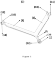
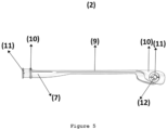
- the longitudinal straps (7, 8 and 9) also have a hollow space (12) ( Figure 1 ) at their most distal ends, which pass through cavities (4) of the flexible sole (1) ( Figure 13 ) and fit tightly to the stoppers (3).
- the central longitudinal strap (7) part, located between the upper protuberance (10) and the lower protuberance (11), has a larger diameter than the rest of this strap, resulting in a firmer fit on the sole (1) ( Figure 1 ).
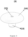
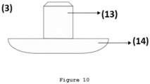
- the present invention presents stoppers (3) made of rigid plastic, equipped with a smaller diameter region (13) ( Figure 6 ), which fits perfectly into the hollow space (12) of the distal ends of the upper (2) ( Figure 11 ), and a larger diameter region (14) that covers the lower protuberance (11) of the ends of the upper (2), and firmly attaches to the bottom part (6) of the sole (1) ( Figure 14 ).
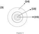
- the stoppers (3) also have a central hole (15), which serves to escape the air inside the hollow spaces (12) of the upper (2) ( Figure 11 ), since the fit is tight.
Landscapes
- Footwear And Its Accessory, Manufacturing Method And Apparatuses (AREA)
Description
- The present invention refers to a sandal with a structural arrangement for attaching uppers on flexible soles of sandals, more specifically to a mechanism for the double fitting of uppers on flexible soles of sandals (flip-flop sandals).
- Flip-flop sandals have a conventional construction consisting of an upper containing a central cylindrical longitudinal strap that attaches to the sole between the first toe (hallux) and the second toe, while two other cylindrical longitudinal straps extend laterally from the central strap, surrounding the user's feet, and attaching to both sides of the sandal. Some models may show differentiation in the places where the upper straps are attached, but the wrapping structure of the user's feet remains fundamentally the same.
- This construction allows the sandal to remain attached to the user's feet when moving, such as walking, maintaining an upper traction force between the user's instep and the sole of the sandal. Thus, the greatest friction and wear caused by movement are concentrated on the user's instep - causing the manufacture of uppers in rubberized and flexible materials in order to reduce friction and irritation with human skin - and in the three fitting points of the upper to the sole of the sandal, namely between the hallux and the second toe and on both sides of the feet.
- The problem with this concept is that its construction is fragile when the user's movement is intense. In the face of a run, for example, the traction shown at the three points of attachment to the sole is too high, causing the disengagement of the upper from the sole - a situation in which the user needs to stop and re-fit it, forcing the entry and making the structure as a whole even more fragile - or permanently damaging the structure - either due to the damage to the sole that tears and can no longer properly attach the upper or due to the upper partition, which no longer has one or more of the three attachment structures to the sole of the sandal.
- Faced with this problem, some solutions have been proposed and can be seen in the prior art. Document
BR PI 1000911 - The document
BR MU8 702 350 U2 - Document
BR 6801346 U - Document
BR PI 0 604 324 - Document
BR PI 0 921 316 - In light of the prior art documents presented and the problems mentioned, the present invention presents a structural arrangement of flip-flop sandals, wherein the upper remains firmly in contact with the user's instep and has attachment structures to the sole, allowing the upper to firmly adhere to it, and providing the realization of intense movements by the user, such as race, without the detachment of the upper or leave the user's foot.
- One of the objectives of the present invention is to provide a structural arrangement for attaching upper to the soles of flip-flop sandals in order to ensure that the upper does not come loose during intense user movements.
- Another objective of the present invention is to provide an upper for flip-flop sandals that are comfortable and firmly suited to the user's instep without coming loose during intense movements.
- A third objective of the present invention is to provide an attachment mechanism of upper to the sole of flip-flop sandals that is functional and of easy production.
- The present invention allows the practical construction, and without extra costs, of flip-flop sandals that remains in firm contact with the user's instep and has attachment structures to the sole, allowing the upper to firmly adhere to it, and providing the realization of intense movements by the user, such as race, without the concern of the detachment of the upper or leave the user's feet.
- The objectives of the present invention are achieved according to the
claim 1 through a structural arrangement with double fitting, wherein the upper straps (containing hollow spaces at their ends) pass through the upper surface of the flexible sole of the sandal, which contains cavities, until the bottom surface, where they find stopper that fit them. Such stoppers have pins for attaching the upper and a region of larger diameter than the cavity in the sole, securely fastening the upper. - The flexible sole of the sandal has three cavities that pass through its entire dimension, communicating the upper part (which is in contact with the user's feet) with the lower part (which is in contact with the ground).
- The upper is a unique flexible structure and has three attaching ends - between the hallux and the second toe, as well as on the sides of the user's foot. Each end of the upper has small protuberances in contact with both upper and lower surfaces of the flexible sole in order to increase the grip and a hollow space in the most distal region that passes through the cavities of the flexible sole and fits tightly to the stopper.
- Stoppers are rigid plastic elements that have a central pin-shaped structure with a central hole and fit into the hollow spaces at ends of the upper. As the stoppers have a diameter much larger than the diameter of the hollow space, they overlap the lower protuberances and are firmly attached to the bottom of the sole.
- The proposed structural arrangement, therefore, presents a first resistance to the removal of the upper by the lower and upper protuberances thereof, and a second resistance, due to the rigid plastic stopper that keeps the upper attached through the fitting to the stoppers and the bottom of the sole. The present construction ensures that the traction force made by intense movements of the user is supported and distributed by the assembly of parts of the fitting mechanism, causing the force that pulls the upper upwards during the movement to be counterbalanced by the downwards force of the rigid plastic stoppers.
- In the following, the present invention is described in more detail regarding the drawings.
-
Figure 1 is a top perspective view of the upper. -
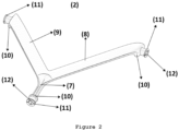
Figure 2 is a top view of the upper. -
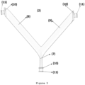
Figure 3 is a bottom view of the upper. -
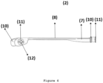
Figure 4 is a right side view of the upper. -
Figure 5 is a left side view of the upper. -
Figure 6 is a top perspective view of the rigid plastic stopper. -
Figure 7 is a bottom perspective view of the rigid plastic stopper. -
Figure 8 is a top view of the rigid plastic stopper. -
Figure 9 is a bottom view of the rigid plastic stopper. -
Figure 10 is a side view of the rigid plastic stopper. -
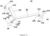
Figure 11 is a bottom perspective view of the detached rigid plastic stopper and upper assembly. -
Figure 12 is a bottom perspective view of the attached rigid plastic stopper and upper assembly. -
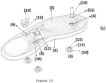
Figure 13 is a top perspective view of the positioning of the attachment mechanism structures. -
Figure 14 is a bottom perspective view of the positioning of the attachment mechanism structures. -
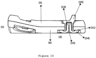
Figure 15 is a cross-section side view of the attachment mechanism. - The object of the present invention is preferably manufactured in plastic with characteristics such as flexibility and high durability, which allow its use for a long time. However, any other materials of compatible durability and flexibility can be applied, such as vegetable fibers. Likewise, other upper shapes are included in the scope of protection of the object of this invention, as defined by
claim 1, since the functionality of the upper attachment mechanism remains unaffected. - Referring to the above-mentioned figures and according to
Figure 1 , the present invention comprises a flexible Y-shaped upper (2), equipped with three longitudinal straps, the main strap being cylindrical in shape (7) positioned between the hallux and the second toe, and two other side straps starting from the main strap, one covering the right side (8) and the other covering the left side (9) of the user's feet. - Also according to
Figure 1 andFigure 3 to 13 , each of the longitudinal straps (7, 8 and 9) of the upper (2) has two small protuberances (10 and 11), one in contact with the upper surface (5) of the flexible sole (1) and the user's feet, and another in contact with the lower surface (6) of the flexible sole (1) and, according to the present invention, the stopper (3) (Figure 13 ). According to the present invention, the longitudinal straps (7, 8 and 9) also have a hollow space (12) (Figure 1 ) at their most distal ends, which pass through cavities (4) of the flexible sole (1) (Figure 13 ) and fit tightly to the stoppers (3). The central longitudinal strap (7) part, located between the upper protuberance (10) and the lower protuberance (11), has a larger diameter than the rest of this strap, resulting in a firmer fit on the sole (1) (Figure 1 ). - Also according to
Figures 6 ,11 and14 , the present invention presents stoppers (3) made of rigid plastic, equipped with a smaller diameter region (13) (Figure 6 ), which fits perfectly into the hollow space (12) of the distal ends of the upper (2) (Figure 11 ), and a larger diameter region (14) that covers the lower protuberance (11) of the ends of the upper (2), and firmly attaches to the bottom part (6) of the sole (1) (Figure 14 ). The stoppers (3) also have a central hole (15), which serves to escape the air inside the hollow spaces (12) of the upper (2) (Figure 11 ), since the fit is tight. - It is possible to see in
Figure 12 the upper (2) with each of the longitudinal straps (7, 8, and 9) fitted with stoppers (3). - In
Figures 13 and14 , on the other hand, all the component structures of the fitting mechanism proposed in the present invention are observed, comprising: the ends of the upper (2) with the upper protuberance (10) and lower protuberance (11); the upper surface (5) and lower surface (6) of the sole (1), in addition to the cavities (4) of the sole (1); and the stoppers (3) comprising the region with the smallest diameter (13), the largest diameter (14) and the central hole (15). It is also possible to notice recesses in the sole (1) both on the upper surface (5) (Figure 13 ) and on the lower surface (6) (Figure 14 ). These recesses receive both the upper protuberance (10) and the larger diameter part (13) of the stopper (3), which covers the lower protuberance of the upper (2). - Finally, it is possible to see a detailed view of the fitting mechanism in
Figure 15 , where the upper protuberance (10) of the upper (2) in contact with the upper surface (5) of the sole (1) and passing through the cavity is observed (4), where the lower protuberance (11) of the upper (2) attaches to the lower surface (6) of the sole (1). It is also possible to visualize the hollow space (12) of the upper (2), which receives the region with the smallest diameter (13) of the stopper (3), while the region with the largest diameter (14) of the stopper (3) covers the lower protuberance (11) of the upper (2), creating a hook mechanism. It is also possible to perceive the channel for the escape of air through the central hole (15) of the stopper (3), which escapes from the hollow space (12) of the upper (2) during the moment of fitting with the largest diameter region (14) the stopper (3).
Claims (1)
- Sandal comprising a flexible sole (1) and a flexible upper (2), said flexible upper (2) consisting of a main longitudinal strap (7) and two side longitudinal straps (8 and 9) leaving it, each strap (7,8,9) comprises, in his more distal region, one upper protuberance (10) which is in contact with an upper surface (5) of said flexible sole (1), a lower protuberance (11) which is in contact with the lower surface (6) of the said flexible sole (1) characterized in that the straps (7,8,9) also each comprise, in their more distal region a hollow space (12) that passes through a corresponding cavity (4) in the flexible sole (1) and receives, in its interior, a region with a smaller diameter (13) of a rigid plastic stopper (3), said stopper which still has a region of larger diameter (14) that overlies the lower protuberance (11) of the most distal end of the upper (2), as well as a central hole (15) which connects the inside of the hollow space (12) to the outside environment.
Applications Claiming Priority (2)
| Application Number | Priority Date | Filing Date | Title |
|---|---|---|---|
| BR202018002676-9U BR202018002676Y1 (en) | 2018-02-08 | 2018-02-08 | CONSTRUCTIVE LEATHER ARRANGEMENT IN SANDALS |
| PCT/BR2019/050035 WO2019153063A1 (en) | 2018-02-08 | 2019-02-07 | Structural arrangement of uppers on sandals |
Publications (4)
| Publication Number | Publication Date |
|---|---|
| EP3750443A1 EP3750443A1 (en) | 2020-12-16 |
| EP3750443A4 EP3750443A4 (en) | 2021-04-28 |
| EP3750443B1 true EP3750443B1 (en) | 2023-07-26 |
| EP3750443C0 EP3750443C0 (en) | 2023-07-26 |
Family
ID=67547784
Family Applications (1)
| Application Number | Title | Priority Date | Filing Date |
|---|---|---|---|
| EP19750677.7A Active EP3750443B1 (en) | 2018-02-08 | 2019-02-07 | Sandal |
Country Status (4)
| Country | Link |
|---|---|
| US (1) | US11382381B2 (en) |
| EP (1) | EP3750443B1 (en) |
| BR (1) | BR202018002676Y1 (en) |
| WO (1) | WO2019153063A1 (en) |
Families Citing this family (2)
| Publication number | Priority date | Publication date | Assignee | Title |
|---|---|---|---|---|
| USD1083319S1 (en) * | 2021-11-22 | 2025-07-15 | Camel Toe Footwear PTY LTD | Double plug toe thong footwear |
| USD1030264S1 (en) * | 2022-05-18 | 2024-06-11 | Crocs, Inc. | Footwear |
Family Cites Families (21)
| Publication number | Priority date | Publication date | Assignee | Title |
|---|---|---|---|---|
| US3553754A (en) * | 1968-01-15 | 1971-01-12 | Merlin Moulded Rubber Manufact | Method of manufacturing uppers for footwear of the sandal type, and to uppers produced by such method |
| US3890725A (en) * | 1973-09-14 | 1975-06-24 | Lea Darrel Bernard | Shoe construction |
| US4864736A (en) * | 1988-05-27 | 1989-09-12 | Ad Impressions, Inc. | Thong sandal with durable toe tab for use as promotional item or the like |
| BR6801346U (en) | 1988-06-17 | 1990-02-13 | Grendene Sa | CONSTRUCTIVE ARRAY IN CHINELO |
| IT1311653B1 (en) * | 1999-09-07 | 2002-03-14 | Perin S P A | FOOTWEAR STRUCTURE, ESPECIALLY A SANDAL. |
| FR2874794A1 (en) | 2004-09-03 | 2006-03-10 | Yves Sitbon | Thong type footwear e.g. light sandal, for use as beach article, has inter-toe support to maintain footwear at foot of user using thin fixing straps that are set in removable manner by metallic rod, which is housed in recess of sole |
| BRPI0600995A (en) | 2006-03-22 | 2007-11-27 | Silvana Belancieri Vasques Epp | process for obtaining ergonomically forked strap applied to slipper-type footwear and resulting product |
| US7694436B2 (en) * | 2006-10-13 | 2010-04-13 | Scott Mullen | Footwear repair |
| BRPI0604324A (en) * | 2006-10-20 | 2008-06-10 | Sonia Regina Saad Whitaker | sole strap fastening of flip flops or sandals |
| BRMU8702350U2 (en) * | 2007-11-05 | 2009-07-07 | Jose De Melo Curi | replaceable strap arrangement for sandals |
| IT1391986B1 (en) | 2008-11-18 | 2012-02-02 | Giovannetti | CIABATTA OF PERFECT TYPE |
| US8171654B2 (en) * | 2009-02-25 | 2012-05-08 | Dream Weaverz Lifewear Llc | Modular open-toe footwear retaining system |
| US8448351B2 (en) | 2009-10-29 | 2013-05-28 | Nike, Inc. | Article of footwear with straps |
| BRPI1000911A2 (en) | 2010-03-15 | 2012-01-17 | Grendene Sa | sole fixing device to the sole, footwear, and process for its production and / or assembly |
| US9155350B2 (en) * | 2011-05-12 | 2015-10-13 | Tizzi, Inc. | Systems and methods for improved customizable, embellished footwear |
| US9072338B1 (en) * | 2011-06-20 | 2015-07-07 | James Kostecky | Interchangeable footwear assembly |
| BR202012019252Y1 (en) | 2012-08-01 | 2018-11-13 | Industria de Calçados Vivo Ltda | constructive arrangement applied to footwear. |
| US9078487B2 (en) * | 2013-01-31 | 2015-07-14 | Deckers Outdoor Corporation | Footwear including a removable and replaceable upper |
| US9380836B1 (en) * | 2013-09-11 | 2016-07-05 | Johnny R. Vigil | Sandal strap repair device |
| US10172410B2 (en) | 2014-02-10 | 2019-01-08 | 29 Ps Pty Ltd. | Footwear |
| US9961956B2 (en) * | 2016-03-09 | 2018-05-08 | Robert Williams | Modular sandal |
-
2018
- 2018-02-08 BR BR202018002676-9U patent/BR202018002676Y1/en active IP Right Grant
-
2019
- 2019-02-07 WO PCT/BR2019/050035 patent/WO2019153063A1/en not_active Ceased
- 2019-02-07 EP EP19750677.7A patent/EP3750443B1/en active Active
- 2019-02-07 US US16/968,653 patent/US11382381B2/en not_active Expired - Fee Related
Also Published As
| Publication number | Publication date |
|---|---|
| US20200405004A1 (en) | 2020-12-31 |
| BR202018002676Y1 (en) | 2020-01-07 |
| EP3750443A1 (en) | 2020-12-16 |
| EP3750443C0 (en) | 2023-07-26 |
| US11382381B2 (en) | 2022-07-12 |
| EP3750443A4 (en) | 2021-04-28 |
| BR202018002676U2 (en) | 2019-08-27 |
| WO2019153063A1 (en) | 2019-08-15 |
Similar Documents
| Publication | Publication Date | Title |
|---|---|---|
| KR100720653B1 (en) | Elastic shoes | |
| JP3014857U (en) | Retractable shoes | |
| US9044062B2 (en) | Convertible shoe | |
| CN102595948B (en) | There is the article of footwear of band | |
| US20130255106A1 (en) | Assembled footwear | |
| BR102012013203A2 (en) | buttress structure for a footwear | |
| US9044060B2 (en) | Convertible shoe | |
| US20080022557A1 (en) | Method of construction and footware using mated components | |
| AU2012259515A1 (en) | Sandal, set of a sandal and strips and method for forming a sandal | |
| CN105661739B (en) | Article of footwear with thong including groove | |
| US11382381B2 (en) | Structural arrangement of uppers on sandals | |
| US9918513B2 (en) | Reversible protective footwear | |
| CN211483183U (en) | Fly-knitted vamp | |
| JP3083819B1 (en) | footwear | |
| JP2024039656A (en) | Insole and shoes equipped with it | |
| JP3209119U (en) | Socks shoes that can integrate shoes and feet | |
| ITVR970034U1 (en) | INTERMEDIATE ELEMENT FOR FOOTWEAR | |
| JP2020025844A (en) | Inner sole and shoe including the same | |
| JP5254929B2 (en) | Fishing boots | |
| CN217218289U (en) | Sole and medical shoes | |
| KR20130038114A (en) | The footwear of length regulation | |
| JP3180971U (en) | Insoles and footwear | |
| US20150113833A1 (en) | Removable accessories for footwear and footwear with removable accessories | |
| JP2020014817A5 (en) | ||
| JP3132207U (en) | Shoes using elastic materials such as woven rubber |
Legal Events
| Date | Code | Title | Description |
|---|---|---|---|
| STAA | Information on the status of an ep patent application or granted ep patent |
Free format text: STATUS: THE INTERNATIONAL PUBLICATION HAS BEEN MADE |
|
| PUAI | Public reference made under article 153(3) epc to a published international application that has entered the european phase |
Free format text: ORIGINAL CODE: 0009012 |
|
| STAA | Information on the status of an ep patent application or granted ep patent |
Free format text: STATUS: REQUEST FOR EXAMINATION WAS MADE |
|
| 17P | Request for examination filed |
Effective date: 20200902 |
|
| AK | Designated contracting states |
Kind code of ref document: A1 Designated state(s): AL AT BE BG CH CY CZ DE DK EE ES FI FR GB GR HR HU IE IS IT LI LT LU LV MC MK MT NL NO PL PT RO RS SE SI SK SM TR |
|
| AX | Request for extension of the european patent |
Extension state: BA ME |
|
| RIN1 | Information on inventor provided before grant (corrected) |
Inventor name: SIMON, PETER |
|
| REG | Reference to a national code |
Ref country code: DE Ipc: A43B0003100000 Ref country code: DE Ref legal event code: R079 Ref document number: 602019033577 Country of ref document: DE Free format text: PREVIOUS MAIN CLASS: A47B0003100000 Ipc: A43B0003100000 |
|
| A4 | Supplementary search report drawn up and despatched |
Effective date: 20210330 |
|
| RIC1 | Information provided on ipc code assigned before grant |
Ipc: A43B 3/10 20060101AFI20210324BHEP Ipc: A43B 3/12 20060101ALI20210324BHEP |
|
| DAV | Request for validation of the european patent (deleted) | ||
| DAX | Request for extension of the european patent (deleted) | ||
| GRAP | Despatch of communication of intention to grant a patent |
Free format text: ORIGINAL CODE: EPIDOSNIGR1 |
|
| STAA | Information on the status of an ep patent application or granted ep patent |
Free format text: STATUS: GRANT OF PATENT IS INTENDED |
|
| INTG | Intention to grant announced |
Effective date: 20230314 |
|
| GRAS | Grant fee paid |
Free format text: ORIGINAL CODE: EPIDOSNIGR3 |
|
| GRAA | (expected) grant |
Free format text: ORIGINAL CODE: 0009210 |
|
| STAA | Information on the status of an ep patent application or granted ep patent |
Free format text: STATUS: THE PATENT HAS BEEN GRANTED |
|
| AK | Designated contracting states |
Kind code of ref document: B1 Designated state(s): AL AT BE BG CH CY CZ DE DK EE ES FI FR GB GR HR HU IE IS IT LI LT LU LV MC MK MT NL NO PL PT RO RS SE SI SK SM TR |
|
| REG | Reference to a national code |
Ref country code: CH Ref legal event code: EP |
|
| REG | Reference to a national code |
Ref country code: IE Ref legal event code: FG4D |
|
| REG | Reference to a national code |
Ref country code: DE Ref legal event code: R096 Ref document number: 602019033577 Country of ref document: DE |
|
| U01 | Request for unitary effect filed |
Effective date: 20230804 |
|
| U07 | Unitary effect registered |
Designated state(s): AT BE BG DE DK EE FI FR IT LT LU LV MT NL PT SE SI Effective date: 20230810 |
|
| REG | Reference to a national code |
Ref country code: LT Ref legal event code: MG9D |
|
| PG25 | Lapsed in a contracting state [announced via postgrant information from national office to epo] |
Ref country code: GR Free format text: LAPSE BECAUSE OF FAILURE TO SUBMIT A TRANSLATION OF THE DESCRIPTION OR TO PAY THE FEE WITHIN THE PRESCRIBED TIME-LIMIT Effective date: 20231027 |
|
| PG25 | Lapsed in a contracting state [announced via postgrant information from national office to epo] |
Ref country code: IS Free format text: LAPSE BECAUSE OF FAILURE TO SUBMIT A TRANSLATION OF THE DESCRIPTION OR TO PAY THE FEE WITHIN THE PRESCRIBED TIME-LIMIT Effective date: 20231126 |
|
| PG25 | Lapsed in a contracting state [announced via postgrant information from national office to epo] |
Ref country code: RS Free format text: LAPSE BECAUSE OF FAILURE TO SUBMIT A TRANSLATION OF THE DESCRIPTION OR TO PAY THE FEE WITHIN THE PRESCRIBED TIME-LIMIT Effective date: 20230726 Ref country code: NO Free format text: LAPSE BECAUSE OF FAILURE TO SUBMIT A TRANSLATION OF THE DESCRIPTION OR TO PAY THE FEE WITHIN THE PRESCRIBED TIME-LIMIT Effective date: 20231026 Ref country code: IS Free format text: LAPSE BECAUSE OF FAILURE TO SUBMIT A TRANSLATION OF THE DESCRIPTION OR TO PAY THE FEE WITHIN THE PRESCRIBED TIME-LIMIT Effective date: 20231126 Ref country code: HR Free format text: LAPSE BECAUSE OF FAILURE TO SUBMIT A TRANSLATION OF THE DESCRIPTION OR TO PAY THE FEE WITHIN THE PRESCRIBED TIME-LIMIT Effective date: 20230726 Ref country code: GR Free format text: LAPSE BECAUSE OF FAILURE TO SUBMIT A TRANSLATION OF THE DESCRIPTION OR TO PAY THE FEE WITHIN THE PRESCRIBED TIME-LIMIT Effective date: 20231027 |
|
| PG25 | Lapsed in a contracting state [announced via postgrant information from national office to epo] |
Ref country code: PL Free format text: LAPSE BECAUSE OF FAILURE TO SUBMIT A TRANSLATION OF THE DESCRIPTION OR TO PAY THE FEE WITHIN THE PRESCRIBED TIME-LIMIT Effective date: 20230726 |
|
| U20 | Renewal fee for the european patent with unitary effect paid |
Year of fee payment: 6 Effective date: 20240223 |
|
| PG25 | Lapsed in a contracting state [announced via postgrant information from national office to epo] |
Ref country code: ES Free format text: LAPSE BECAUSE OF FAILURE TO SUBMIT A TRANSLATION OF THE DESCRIPTION OR TO PAY THE FEE WITHIN THE PRESCRIBED TIME-LIMIT Effective date: 20230726 |
|
| REG | Reference to a national code |
Ref country code: DE Ref legal event code: R097 Ref document number: 602019033577 Country of ref document: DE |
|
| PG25 | Lapsed in a contracting state [announced via postgrant information from national office to epo] |
Ref country code: SM Free format text: LAPSE BECAUSE OF FAILURE TO SUBMIT A TRANSLATION OF THE DESCRIPTION OR TO PAY THE FEE WITHIN THE PRESCRIBED TIME-LIMIT Effective date: 20230726 Ref country code: RO Free format text: LAPSE BECAUSE OF FAILURE TO SUBMIT A TRANSLATION OF THE DESCRIPTION OR TO PAY THE FEE WITHIN THE PRESCRIBED TIME-LIMIT Effective date: 20230726 Ref country code: ES Free format text: LAPSE BECAUSE OF FAILURE TO SUBMIT A TRANSLATION OF THE DESCRIPTION OR TO PAY THE FEE WITHIN THE PRESCRIBED TIME-LIMIT Effective date: 20230726 Ref country code: CZ Free format text: LAPSE BECAUSE OF FAILURE TO SUBMIT A TRANSLATION OF THE DESCRIPTION OR TO PAY THE FEE WITHIN THE PRESCRIBED TIME-LIMIT Effective date: 20230726 Ref country code: SK Free format text: LAPSE BECAUSE OF FAILURE TO SUBMIT A TRANSLATION OF THE DESCRIPTION OR TO PAY THE FEE WITHIN THE PRESCRIBED TIME-LIMIT Effective date: 20230726 |
|
| PLBE | No opposition filed within time limit |
Free format text: ORIGINAL CODE: 0009261 |
|
| STAA | Information on the status of an ep patent application or granted ep patent |
Free format text: STATUS: NO OPPOSITION FILED WITHIN TIME LIMIT |
|
| 26N | No opposition filed |
Effective date: 20240429 |
|
| PG25 | Lapsed in a contracting state [announced via postgrant information from national office to epo] |
Ref country code: MC Free format text: LAPSE BECAUSE OF FAILURE TO SUBMIT A TRANSLATION OF THE DESCRIPTION OR TO PAY THE FEE WITHIN THE PRESCRIBED TIME-LIMIT Effective date: 20230726 |
|
| REG | Reference to a national code |
Ref country code: CH Ref legal event code: PL |
|
| PG25 | Lapsed in a contracting state [announced via postgrant information from national office to epo] |
Ref country code: CH Free format text: LAPSE BECAUSE OF NON-PAYMENT OF DUE FEES Effective date: 20240229 |
|
| GBPC | Gb: european patent ceased through non-payment of renewal fee |
Effective date: 20240207 |
|
| PG25 | Lapsed in a contracting state [announced via postgrant information from national office to epo] |
Ref country code: CH Free format text: LAPSE BECAUSE OF NON-PAYMENT OF DUE FEES Effective date: 20240229 |
|
| PG25 | Lapsed in a contracting state [announced via postgrant information from national office to epo] |
Ref country code: GB Free format text: LAPSE BECAUSE OF NON-PAYMENT OF DUE FEES Effective date: 20240207 |
|
| PG25 | Lapsed in a contracting state [announced via postgrant information from national office to epo] |
Ref country code: IE Free format text: LAPSE BECAUSE OF NON-PAYMENT OF DUE FEES Effective date: 20240207 |
|
| PG25 | Lapsed in a contracting state [announced via postgrant information from national office to epo] |
Ref country code: IE Free format text: LAPSE BECAUSE OF NON-PAYMENT OF DUE FEES Effective date: 20240207 Ref country code: GB Free format text: LAPSE BECAUSE OF NON-PAYMENT OF DUE FEES Effective date: 20240207 |
|
| PG25 | Lapsed in a contracting state [announced via postgrant information from national office to epo] |
Ref country code: CY Free format text: LAPSE BECAUSE OF FAILURE TO SUBMIT A TRANSLATION OF THE DESCRIPTION OR TO PAY THE FEE WITHIN THE PRESCRIBED TIME-LIMIT; INVALID AB INITIO Effective date: 20190207 |
|
| PG25 | Lapsed in a contracting state [announced via postgrant information from national office to epo] |
Ref country code: HU Free format text: LAPSE BECAUSE OF FAILURE TO SUBMIT A TRANSLATION OF THE DESCRIPTION OR TO PAY THE FEE WITHIN THE PRESCRIBED TIME-LIMIT; INVALID AB INITIO Effective date: 20190207 |
|
| U90 | Renewal fees not paid: noting of loss of rights |
Free format text: RENEWAL FEE NOT PAID FOR YEAR 07 Effective date: 20250919 |
|
| PG25 | Lapsed in a contracting state [announced via postgrant information from national office to epo] |
Ref country code: TR Free format text: LAPSE BECAUSE OF FAILURE TO SUBMIT A TRANSLATION OF THE DESCRIPTION OR TO PAY THE FEE WITHIN THE PRESCRIBED TIME-LIMIT Effective date: 20230726 |
|
| U93 | Unitary patent lapsed |
Free format text: RENEWAL FEE NOT PAID Effective date: 20250228 |