EP3750224B1 - Apparatus and methods for reducing generator frequency variation - Google Patents
Apparatus and methods for reducing generator frequency variation Download PDFInfo
- Publication number
- EP3750224B1 EP3750224B1 EP19709587.0A EP19709587A EP3750224B1 EP 3750224 B1 EP3750224 B1 EP 3750224B1 EP 19709587 A EP19709587 A EP 19709587A EP 3750224 B1 EP3750224 B1 EP 3750224B1
- Authority
- EP
- European Patent Office
- Prior art keywords
- bias
- load sharing
- frequency
- controller
- signal
- Prior art date
- Legal status (The legal status is an assumption and is not a legal conclusion. Google has not performed a legal analysis and makes no representation as to the accuracy of the status listed.)
- Active
Links
Images


Classifications
-
- H—ELECTRICITY
- H02—GENERATION; CONVERSION OR DISTRIBUTION OF ELECTRIC POWER
- H02J—ELECTRIC POWER NETWORKS; CIRCUIT ARRANGEMENTS OR SYSTEMS FOR SUPPLYING OR DISTRIBUTING ELECTRIC POWER; SYSTEMS FOR STORING ELECTRIC ENERGY
- H02J3/00—Circuit arrangements for AC mains or AC distribution networks
- H02J3/38—Arrangements for feeding a single network from two or more generators or sources in parallel; Arrangements for feeding already energised networks from additional generators or sources in parallel
- H02J3/381—Dispersed generators
-
- G—PHYSICS
- G05—CONTROLLING; REGULATING
- G05B—CONTROL OR REGULATING SYSTEMS IN GENERAL; FUNCTIONAL ELEMENTS OF SUCH SYSTEMS; MONITORING OR TESTING ARRANGEMENTS FOR SUCH SYSTEMS OR ELEMENTS
- G05B19/00—Program-control systems
- G05B19/02—Program-control systems electric
- G05B19/04—Program control other than numerical control, i.e. in sequence controllers or logic controllers
- G05B19/042—Program control other than numerical control, i.e. in sequence controllers or logic controllers using digital processors
-
- H—ELECTRICITY
- H02—GENERATION; CONVERSION OR DISTRIBUTION OF ELECTRIC POWER
- H02J—ELECTRIC POWER NETWORKS; CIRCUIT ARRANGEMENTS OR SYSTEMS FOR SUPPLYING OR DISTRIBUTING ELECTRIC POWER; SYSTEMS FOR STORING ELECTRIC ENERGY
- H02J3/00—Circuit arrangements for AC mains or AC distribution networks
- H02J3/28—Arrangements for balancing of the load in networks by storage of energy
- H02J3/32—Arrangements for balancing of the load in networks by storage of energy using batteries or super capacitors with converting means
-
- H—ELECTRICITY
- H02—GENERATION; CONVERSION OR DISTRIBUTION OF ELECTRIC POWER
- H02J—ELECTRIC POWER NETWORKS; CIRCUIT ARRANGEMENTS OR SYSTEMS FOR SUPPLYING OR DISTRIBUTING ELECTRIC POWER; SYSTEMS FOR STORING ELECTRIC ENERGY
- H02J3/00—Circuit arrangements for AC mains or AC distribution networks
- H02J3/38—Arrangements for feeding a single network from two or more generators or sources in parallel; Arrangements for feeding already energised networks from additional generators or sources in parallel
- H02J3/46—Controlling the sharing of generated power between the generators, sources or networks
-
- H—ELECTRICITY
- H02—GENERATION; CONVERSION OR DISTRIBUTION OF ELECTRIC POWER
- H02P—CONTROL OR REGULATION OF ELECTRIC MOTORS, ELECTRIC GENERATORS OR DYNAMO-ELECTRIC CONVERTERS; CONTROLLING TRANSFORMERS, REACTORS OR CHOKE COILS
- H02P9/00—Arrangements for controlling electric generators for the purpose of obtaining a desired output
- H02P9/02—Details of the control
-
- G—PHYSICS
- G05—CONTROLLING; REGULATING
- G05B—CONTROL OR REGULATING SYSTEMS IN GENERAL; FUNCTIONAL ELEMENTS OF SUCH SYSTEMS; MONITORING OR TESTING ARRANGEMENTS FOR SUCH SYSTEMS OR ELEMENTS
- G05B2219/00—Program-control systems
- G05B2219/20—Pc systems
- G05B2219/26—Pc applications
- G05B2219/2639—Energy management, use maximum of cheap power, keep peak load low
-
- H—ELECTRICITY
- H02—GENERATION; CONVERSION OR DISTRIBUTION OF ELECTRIC POWER
- H02J—ELECTRIC POWER NETWORKS; CIRCUIT ARRANGEMENTS OR SYSTEMS FOR SUPPLYING OR DISTRIBUTING ELECTRIC POWER; SYSTEMS FOR STORING ELECTRIC ENERGY
- H02J2101/00—Supply or distribution of decentralised, dispersed or local electric power generation
- H02J2101/10—Dispersed power generation using fossil fuels, e.g. diesel generators
-
- H—ELECTRICITY
- H02—GENERATION; CONVERSION OR DISTRIBUTION OF ELECTRIC POWER
- H02J—ELECTRIC POWER NETWORKS; CIRCUIT ARRANGEMENTS OR SYSTEMS FOR SUPPLYING OR DISTRIBUTING ELECTRIC POWER; SYSTEMS FOR STORING ELECTRIC ENERGY
- H02J3/00—Circuit arrangements for AC mains or AC distribution networks
- H02J3/38—Arrangements for feeding a single network from two or more generators or sources in parallel; Arrangements for feeding already energised networks from additional generators or sources in parallel
- H02J3/388—Arrangements for the handling of islanding, e.g. for disconnection or for avoiding the disconnection of power
Definitions
- generation assets such as diesel or gas powered generators and turbines
- transient load conditions may include, for example, large load changes and sudden changes in power source availability, such as a generation asset shutting down or becoming unavailable.
- Such variations in line frequency or voltage may result in dropped loads or damaged equipment.
- Some island grids may be supported by one generation asset sized to support the peak load and to respond to large transient load steps. These assets may operate at very high utilization rates, for example, 24 hours a day, 7 days a week, 365 days a year, but at relatively low real load factors, e.g., between 15-50%, for extended periods of off-peak time.
- U.S. Patent No. 9,312,699 to Taimela et al assigned to the assignee of the present application, describes use of a generator in combination with an electronic converter-based Solid State Generator (SSG), which is used to support operation of the generator using energy from an energy storage device, such as a battery or capacitor bank, provided to the grid via a power converter.
- the SSG may be used to provide transient load support and to provide power to the grid when the generator is inactive.
- WO 2012/159678 provides a method for regulating system frequency in a weak power system.
- a system in accordance with a first aspect, there is a system as described in claim 1. In accordance with a second aspect, there is a method of operating a system as described in claim 5.
- a system includes a generator configured to be electrically coupled to a grid, an engine configured to drive the generator, and a solid state generator electrically coupled between the grid and an energy storage device.
- the system further includes a bias controller configured to detect a frequency of the grid and to responsively provide a bias signal to a speed controller of the engine.
- the bias controller may include a frequency bias controller configured to generate a frequency bias load sharing signal responsive to the detected frequency of the grid and a load sharing controller that receives the frequency bias load sharing signal and that generates the bias signal responsive to the load sharing signal.
- the frequency bias controller may be configured to control a load sharing line that is used to provide a customer load sharing signal to the load sharing controller.
- the frequency bias controller may be configured to generate the frequency bias load sharing signal responsive to the detected frequency, a state of charge of the energy storage device and an active power output of the SSG.
- the bias controller may be configured to provide the bias signal responsive to a load change in advance of a response of the speed controller to the load change.
- the resultant voltage or frequency variation can be mitigated by using a solid state generator (SSG) that includes a converter and attached energy storage (e.g., a battery and/or supercapacitor) to provide transient load support.
- SSG solid state generator
- the greater load support provided by the SSG the variations in voltage and frequency will be less.
- the less error signal is detected by the generator controls to make the adjustment to the new load conditions.
- generation assets such as diesel or gas powered generators and turbines.
- gas powered generators, turbo-charged generators and turbines can experience considerable delayed response to an increased throttle command. This response delay can increase the required stored energy coupled to the SSG to mitigate the transient variation.
- Generators operating in island grid mode may be subject to large load steps which are a significant percentage of the generator capacity. Such large load steps result in significant frequency and/or load voltage variations that can cause the generation asset to shut down or becoming unavailable. The loss of the generation asset could result in further load bus variations in line frequency or voltage which may result in dropped loads, damaged equipment or grid failure resulting from cascade failures.
- FIG. 1 illustrates a system according to some embodiments.
- the system includes a generator 110 configured to be coupled to a grid 10.
- the generator is mechanically coupled to a prime mover, which may be a natural gas fueled engine 130.
- the engine 130 is equipped with a governor 120 that controls the fuel to the engine cylinders so as to control the speed of the unit, holding the speed constant for all conditions of load imposed on the generator 110.
- the governor 120 When the load is increased, the resultant change is sensed by the governor 120 which responds by adjusting the throttle to return the speed to the desired set point. With increased error, the governor 120 responds with greater throttle adjustment.
- engines that have a delayed response to a throttle command such as natural gas fueled engine or turbine, the delay results in larger and longer frequency and voltage variations with respect to a load change.
- An SSG 150 connects energy storage, such as a battery, to the grid 10 using, for example, a power converter circuit.
- energy storage such as a battery
- the longer the delay in responding to a change in load will require larger amounts of the stored energy connected to the SSG 150.
- tight control over the grid 10 there may be a tradeoff between reducing the error as seen by the governor 120 and the amount of stored energy required. This tradeoff may be exacerbated by the delayed response to throttle commands of some engine types.
- each generator 220, 230, 240 delivers an analog output (0-5V), which is determined by its load level, where full load is 5V and no load is 0V.
- the analog outputs will be averaged to a common load sharing value on the load sharing line 210, using identical pull up resistors.
- the load sharing module will also read the analog input value on the common load sharing line 210.
- the load sharing module may include a differential amplifier to generate a bias signal (e.g. a speed or frequency bias signal), in order to adjust the generator power.
- FIG. 2 Shown in Figure 2 are a first generator 220 and a second generator 230 with their outputs at 5V since their output is at 100% while generator 240 is at 2.5V since their output is at 50% of full load. With the averaging resistor, they read the common line back as 4.16V. In response, the first generator 220 and the second generator 230 see the voltage difference as 0.84V and will reduce their output power in response to this negative bias. Simultaneously, a third generator 240 sees the voltage difference as -1.66V and will increase its output power in response to this positive bias. The generators 220, 230, 240 respond to the differences between their output and the average output of the paralleled generators so the net result is that each of the generators 220, 230, 240 will provide the same percentage of the aggregated generator load.
- a solid state generator comprising an energy storage and associated converter can utilize this commonly available load sharing input to enhance the error signal provided to the governor of the generator beyond that which the governor can extract from the normal frequency and voltage variations during load transients.
- the SSG can provide greater control over the magnitude of frequency and voltage variations which would normally mask the transient from the governor.
- the SSG will provide a signal to a governor having a load sharing input by providing the appropriate magnitude bias to cause the governor to adjust the throttle to the new load conditions. For example, in response to a load step, the SSG may signal the governor to increase throttle far in advance and/or greater magnitude than the governor can determine based on normally available inputs. The result is the generator being able to supply a substantial percentage of the load step during the transient without any significant frequency or voltage variation. Since the generator supplies larger percentage of the transient load step, the stored energy connected to the SSG can be reduced.
- a frequency bias controller 160 is coupled to a load sharing line that is input to the load share module 140.
- the frequency bias controller 160 operates responsive to an SSG 150.
- the frequency bias controller 160 implements a frequency bias algorithm responsive to an output from the SSG 150 that provides an input to the load sharing line input to the load sharing module 140, which responsively produces a speed bias input to the governor 120.
- the output from the SSG 150 may include, for example, information about the frequency of the AC grid 10, an active power output Pssg of the SSG 150 and a state of charge (SOC) of the energy storage of the SSG 150.
- FIG. 3 an exemplary generator bias control approach is presented.
- the bias control takes the input of AC bus frequency, SSG active power, and state of charge in the energy storage system to optimize the controls.
- the bias controls can make the generator response faster, in order to reduce or-minimize the variation on the bus (grid).
- a high pass filter may be added to create the frequency variance, to feed into the PI controller. If an integrator already exists in the load share module, there may be no need for extra integration in the frequency compensator.
- a bias signal can be provided for load step and load drop events, this example provides for positive bias injection to compensate for load step transients. The load drop events may be less problematic for natural gas fueled engines.
- This strategy of an SSG providing bias control to signal the governor of a pending load change in advance of this information by normal control inputs can help optimize energy usage and State of Charge (SOC) management.
- SOC State of Charge
- the inclusion of SOC into consideration, can allow the SSG to operate at higher gain when the SOC is lower. This can enable the SSG to tailor the magnitude of bias to provide a reduced or minimum frequency or voltage variation based on available energy store (SOC) connected to the SSG.
- the switch engine governor/speed controller may be switched to a mode where the throttle is pegged 100% open / closed during a transient condition.
- This allows the hybrid power train (SSG) to take 100% over the control of frequency and voltage of the bus.
- SSG hybrid power train
- the engine may deliver nearly 100% of power and energy based on its operating point by substantially bypassing the engine speed control, which can result in desirable power output with reduced or minimal storage cost.
- the storage controller can re-enable the normal governor/speed controller operation mode.
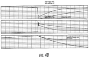
- Figures 4A and 4B illustrate a simulation of the inventive concept illustrating the response with and without bias controls. It can be seen in FIG. 4B that frequency recovers much faster with bias control than without it. In the illustrated simulation, using bias control may result in a 60% savings on the required energy store for the transient event.
Landscapes
- Engineering & Computer Science (AREA)
- Power Engineering (AREA)
- Physics & Mathematics (AREA)
- General Physics & Mathematics (AREA)
- Automation & Control Theory (AREA)
- Control Of Eletrric Generators (AREA)
Description
- In island grid applications, generation assets, such as diesel or gas powered generators and turbines, may experience transient load conditions that can cause changes in grid frequency and voltage. These transient conditions may include, for example, large load changes and sudden changes in power source availability, such as a generation asset shutting down or becoming unavailable. Such variations in line frequency or voltage may result in dropped loads or damaged equipment.
- Some island grids may be supported by one generation asset sized to support the peak load and to respond to large transient load steps. These assets may operate at very high utilization rates, for example, 24 hours a day, 7 days a week, 365 days a year, but at relatively low real load factors, e.g., between 15-50%, for extended periods of off-peak time.
U.S. Patent No. 9,312,699 to Taimela et al -
WO 2012/159678 provides a method for regulating system frequency in a weak power system. - In accordance with a first aspect, there is a system as described in
claim 1. In accordance with a second aspect, there is a method of operating a system as described in claim 5.
According to some embodiments, a system includes a generator configured to be electrically coupled to a grid, an engine configured to drive the generator, and a solid state generator electrically coupled between the grid and an energy storage device. The system further includes a bias controller configured to detect a frequency of the grid and to responsively provide a bias signal to a speed controller of the engine. The bias controller may include a frequency bias controller configured to generate a frequency bias load sharing signal responsive to the detected frequency of the grid and a load sharing controller that receives the frequency bias load sharing signal and that generates the bias signal responsive to the load sharing signal. The frequency bias controller may be configured to control a load sharing line that is used to provide a customer load sharing signal to the load sharing controller. The frequency bias controller may be configured to generate the frequency bias load sharing signal responsive to the detected frequency, a state of charge of the energy storage device and an active power output of the SSG. The bias controller may be configured to provide the bias signal responsive to a load change in advance of a response of the speed controller to the load change. -
-
FIG. 1 illustrates a system according to some embodiments of the inventive subject matter. -
FIG. 2 illustrates load share signaling among generators. -
FIG. 3 illustrates a control architecture for generator bias control according to some embodiments. -
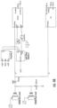
FIGs. 4A and4B illustrate a simulation model and performance characteristics for bias control according to some embodiments. - Specific exemplary embodiments of the inventive subject matter now will be described with reference to the accompanying drawings. This inventive subject matter may, however, be embodied in many different forms and should not be construed as limited to the embodiments set forth herein; rather, these embodiments are provided so that this disclosure will be thorough and complete, and will fully convey the scope of the inventive subject matter to those skilled in the art. In the drawings, like numbers refer to like items. It will be understood that when an item is referred to as being "connected" or "coupled" to another item, it can be directly connected or coupled to the other item or intervening items may be present. As used herein the term "and/or" includes any and all combinations of one or more of the associated listed items.
- The terminology used herein is for the purpose of describing particular embodiments only and is not intended to be limiting of the inventive subject matter. As used herein, the singular forms "a", "an" and "the" are intended to include the plural forms as well, unless expressly stated otherwise. It will be further understood that the terms "includes," "comprises," "including" and/or "comprising," when used in this specification, specify the presence of stated features, integers, steps, operations, items, and/or components, but do not preclude the presence or addition of one or more other features, integers, steps, operations, items, components, and/or groups thereof.
- Unless otherwise defined, all terms (including technical and scientific terms) used herein have the same meaning as commonly understood by one of ordinary skill in the art to which this inventive subject matter belongs. It will be further understood that terms, such as those defined in commonly used dictionaries, should be interpreted as having a meaning that is consistent with their meaning in the context of the specification and the relevant art and will not be interpreted in an idealized or overly formal sense unless expressly so defined herein.
- When a substantial load is connected to the grid, the resultant voltage or frequency variation can be mitigated by using a solid state generator (SSG) that includes a converter and attached energy storage (e.g., a battery and/or supercapacitor) to provide transient load support. The greater load support provided by the SSG, the variations in voltage and frequency will be less. However, with this reduced variation in voltage and frequency, the less error signal is detected by the generator controls to make the adjustment to the new load conditions. This can be observed in generation assets, such as diesel or gas powered generators and turbines. In particular, gas powered generators, turbo-charged generators and turbines can experience considerable delayed response to an increased throttle command. This response delay can increase the required stored energy coupled to the SSG to mitigate the transient variation.
- Generators operating in island grid mode may be subject to large load steps which are a significant percentage of the generator capacity. Such large load steps result in significant frequency and/or load voltage variations that can cause the generation asset to shut down or becoming unavailable. The loss of the generation asset could result in further load bus variations in line frequency or voltage which may result in dropped loads, damaged equipment or grid failure resulting from cascade failures.
-
Figure 1 illustrates a system according to some embodiments. The system includes agenerator 110 configured to be coupled to agrid 10. The generator is mechanically coupled to a prime mover, which may be a natural gas fueledengine 130. Theengine 130 is equipped with agovernor 120 that controls the fuel to the engine cylinders so as to control the speed of the unit, holding the speed constant for all conditions of load imposed on thegenerator 110. When the load is increased, the resultant change is sensed by thegovernor 120 which responds by adjusting the throttle to return the speed to the desired set point. With increased error, thegovernor 120 responds with greater throttle adjustment. With engines that have a delayed response to a throttle command, such as natural gas fueled engine or turbine, the delay results in larger and longer frequency and voltage variations with respect to a load change. - An SSG 150 connects energy storage, such as a battery, to the
grid 10 using, for example, a power converter circuit. When the SSG 150 is operating in a transient support mode, the longer the delay in responding to a change in load will require larger amounts of the stored energy connected to theSSG 150. When tight control over thegrid 10 is required there may be a tradeoff between reducing the error as seen by thegovernor 120 and the amount of stored energy required. This tradeoff may be exacerbated by the delayed response to throttle commands of some engine types. - Governors are commonly available with a
load sharing module 140 that facilitates the load sharing of two or more generators operating in parallel. The operation of generators using a load sharing module is illustrated inFigure 2 . As the schematic diagram illustrates, paralleledgenerator load sharing line 210. In this example, eachgenerator load sharing line 210, using identical pull up resistors. The load sharing module will also read the analog input value on the commonload sharing line 210. Internally, the load sharing module may include a differential amplifier to generate a bias signal (e.g. a speed or frequency bias signal), in order to adjust the generator power. - Shown in
Figure 2 are afirst generator 220 and asecond generator 230 with their outputs at 5V since their output is at 100% whilegenerator 240 is at 2.5V since their output is at 50% of full load. With the averaging resistor, they read the common line back as 4.16V. In response, thefirst generator 220 and thesecond generator 230 see the voltage difference as 0.84V and will reduce their output power in response to this negative bias. Simultaneously, athird generator 240 sees the voltage difference as -1.66V and will increase its output power in response to this positive bias. Thegenerators generators - In some embodiments, a solid state generator (SSG) comprising an energy storage and associated converter can utilize this commonly available load sharing input to enhance the error signal provided to the governor of the generator beyond that which the governor can extract from the normal frequency and voltage variations during load transients. The SSG can provide greater control over the magnitude of frequency and voltage variations which would normally mask the transient from the governor. In some embodiments, the SSG will provide a signal to a governor having a load sharing input by providing the appropriate magnitude bias to cause the governor to adjust the throttle to the new load conditions. For example, in response to a load step, the SSG may signal the governor to increase throttle far in advance and/or greater magnitude than the governor can determine based on normally available inputs. The result is the generator being able to supply a substantial percentage of the load step during the transient without any significant frequency or voltage variation. Since the generator supplies larger percentage of the transient load step, the stored energy connected to the SSG can be reduced.
- Referring again to
Figure 1 , a frequency bias controller 160 is coupled to a load sharing line that is input to theload share module 140. The frequency bias controller 160 operates responsive to anSSG 150. The frequency bias controller 160 implements a frequency bias algorithm responsive to an output from theSSG 150 that provides an input to the load sharing line input to theload sharing module 140, which responsively produces a speed bias input to thegovernor 120. The output from theSSG 150 may include, for example, information about the frequency of theAC grid 10, an active power output Pssg of theSSG 150 and a state of charge (SOC) of the energy storage of theSSG 150. - In
Figure 3 , an exemplary generator bias control approach is presented. The bias control takes the input of AC bus frequency, SSG active power, and state of charge in the energy storage system to optimize the controls. The bias controls can make the generator response faster, in order to reduce or-minimize the variation on the bus (grid). A high pass filter may be added to create the frequency variance, to feed into the PI controller. If an integrator already exists in the load share module, there may be no need for extra integration in the frequency compensator. Although a bias signal can be provided for load step and load drop events, this example provides for positive bias injection to compensate for load step transients. The load drop events may be less problematic for natural gas fueled engines. - The implementation of this strategy of an SSG providing bias control to signal the governor of a pending load change in advance of this information by normal control inputs can help optimize energy usage and State of Charge (SOC) management. The inclusion of SOC into consideration, can allow the SSG to operate at higher gain when the SOC is lower. This can enable the SSG to tailor the magnitude of bias to provide a reduced or minimum frequency or voltage variation based on available energy store (SOC) connected to the SSG.
- Although the invention was described using the load sharing module, it is clear that the inventive concepts could be used or modified to use another input to the generator which can be used to provide advance information of load change resulting in increased throttle in advance of a normal governor response. Therefore, using an alternative communication line to governor, the switch engine governor/speed controller may be switched to a mode where the throttle is pegged 100% open / closed during a transient condition. This allows the hybrid power train (SSG) to take 100% over the control of frequency and voltage of the bus. In a fully optimized hybrid mode, the engine may deliver nearly 100% of power and energy based on its operating point by substantially bypassing the engine speed control, which can result in desirable power output with reduced or minimal storage cost. In this alternate mode, after the SSG has handled the transient and observe steady state condition, the storage controller can re-enable the normal governor/speed controller operation mode.
-
Figures 4A and4B illustrate a simulation of the inventive concept illustrating the response with and without bias controls. It can be seen inFIG. 4B that frequency recovers much faster with bias control than without it. In the illustrated simulation, using bias control may result in a 60% savings on the required energy store for the transient event. - In the drawings and specification, there have been disclosed exemplary embodiments of the inventive subject matter. Although specific terms are employed, they are used in a generic and descriptive sense only and not for purposes of limitation, the scope of the inventive subject matter being defined by the following claims.
Claims (8)
- A system comprising:a generator (110) configured to be electrically coupled to a grid (10);an engine (130) configured to drive the generator (110);a solid state generator, SSG, (150) configured to couple an energy storage device to the grid (10); anda bias controller (160) coupled to the SSG (150) and configured to detect a frequency of the grid (10) and to responsively provide a bias signal that adds to a speed reference signal for a speed controller (120) of the engine (130);characterised in that the bias controller (160) comprises:a frequency bias controller (160) configured to generate a frequency bias load sharing signal responsive to the detected frequency of the grid (10) and to receive an active power output of the SSG, anda load sharing controller (140) configured to receive the frequency bias load sharing signal via a load sharing line coupled to at least one other generator (220, 230, 240), wherein the load sharing controller (140) is configured to generate the bias signal responsive to the load sharing.
- The system of claim 1, wherein the frequency bias controller (160) is configured to control a load sharing line (210) that is used to provide a customer load sharing signal to the load sharing controller (140).
- The system of claim 1, wherein the frequency bias controller (160) is configured to generate the frequency bias load sharing signal responsive to the detected frequency, a state of charge of the energy storage device and an active power output of the SSG (150).
- The system of claim 1, wherein the bias controller (160) is configured to provide the bias signal responsive to a load change in advance of a response of the speed controller (120) to the load change.
- A method of operating a system comprising a generator (110) configured to be electrically coupled to a grid (10), an engine (130) configured to drive the generator (110) and a solid state generator, SSG, (150) that couples the grid (10) to an energy storage device, the method comprising:detecting a frequency of the grid (10); andproviding a bias signal that adds to a speed reference signal for a speed controller (120) of the engine (130) responsive to the detected frequency;characterised in that providing the bias signal comprises:generating a frequency bias load sharing signal responsive to the detected frequency;providing the frequency bias load sharing signal to a load sharing controller (140) for the generator (110) via a load sharing line (210) coupled to at least one other generator (220, 230, 240); andgenerating the bias signal from the load sharing controller (140) responsive to the frequency bias load sharing signal.
- The method of claim 5, wherein generating the frequency bias load sharing signal comprises controlling a load sharing line (210) that is used to provide a customer load sharing signal to the load sharing controller (140).
- The method of claim 5, wherein generating the frequency bias load sharing signal comprises generating the frequency bias load sharing signal responsive to the detected frequency, a state of charge of the energy storage device and an active power output of the SSG (150).
- The method of claim 5, wherein providing the bias signal to the speed controller (120) comprises providing the bias signal responsive to a load change in advance of a response of the speed controller (120) to the load change.
Applications Claiming Priority (2)
| Application Number | Priority Date | Filing Date | Title |
|---|---|---|---|
| US201862627307P | 2018-02-07 | 2018-02-07 | |
| PCT/US2019/016765 WO2019157005A1 (en) | 2018-02-07 | 2019-02-06 | Apparatus and methods for reducing generator frequency variation |
Publications (3)
| Publication Number | Publication Date |
|---|---|
| EP3750224A1 EP3750224A1 (en) | 2020-12-16 |
| EP3750224C0 EP3750224C0 (en) | 2023-11-01 |
| EP3750224B1 true EP3750224B1 (en) | 2023-11-01 |
Family
ID=65686927
Family Applications (1)
| Application Number | Title | Priority Date | Filing Date |
|---|---|---|---|
| EP19709587.0A Active EP3750224B1 (en) | 2018-02-07 | 2019-02-06 | Apparatus and methods for reducing generator frequency variation |
Country Status (5)
| Country | Link |
|---|---|
| US (1) | US11418039B2 (en) |
| EP (1) | EP3750224B1 (en) |
| AU (1) | AU2019217528B2 (en) |
| CA (1) | CA3090669A1 (en) |
| WO (1) | WO2019157005A1 (en) |
Families Citing this family (3)
| Publication number | Priority date | Publication date | Assignee | Title |
|---|---|---|---|---|
| US11394231B2 (en) * | 2019-02-01 | 2022-07-19 | Moser Energy Systems | Hybrid generator system and method of operation and control |
| GB201903895D0 (en) * | 2019-03-21 | 2019-05-08 | Univ Birmingham | Energy system control |
| CA3191916A1 (en) * | 2020-09-11 | 2022-03-17 | Prasanna S. NIRANTARE | Systems and methods for a hybrid power grid |
Family Cites Families (7)
| Publication number | Priority date | Publication date | Assignee | Title |
|---|---|---|---|---|
| US6164057A (en) * | 1999-03-16 | 2000-12-26 | General Electric Co. | Gas turbine generator having reserve capacity controller |
| WO2012159678A1 (en) * | 2011-05-26 | 2012-11-29 | Alstom Technology Ltd | Power system |
| US20140195137A1 (en) * | 2012-03-30 | 2014-07-10 | Honda Motor Co., Ltd. | Internal combustion engine control apparatus and internal combustion engine control method |
| US9312699B2 (en) | 2012-10-11 | 2016-04-12 | Flexgen Power Systems, Inc. | Island grid power supply apparatus and methods using energy storage for transient stabilization |
| EP3090318B1 (en) * | 2013-12-31 | 2020-10-14 | Schneider Electric IT Corporation | Controlling a microgrid |
| US20160160839A1 (en) * | 2014-12-09 | 2016-06-09 | State Grid Corporation Of China | Method for controlling inertia response of variable-speed wind turbine generator |
| CN105946844B (en) * | 2016-04-28 | 2018-09-14 | 广州汽车集团股份有限公司 | The control method and system of hybrid vehicle clutch engagement |
-
2019
- 2019-02-06 CA CA3090669A patent/CA3090669A1/en active Pending
- 2019-02-06 WO PCT/US2019/016765 patent/WO2019157005A1/en not_active Ceased
- 2019-02-06 US US16/968,098 patent/US11418039B2/en active Active
- 2019-02-06 EP EP19709587.0A patent/EP3750224B1/en active Active
- 2019-02-06 AU AU2019217528A patent/AU2019217528B2/en active Active
Also Published As
| Publication number | Publication date |
|---|---|
| AU2019217528B2 (en) | 2023-03-30 |
| AU2019217528A1 (en) | 2020-08-27 |
| US11418039B2 (en) | 2022-08-16 |
| US20210036638A1 (en) | 2021-02-04 |
| WO2019157005A1 (en) | 2019-08-15 |
| EP3750224A1 (en) | 2020-12-16 |
| EP3750224C0 (en) | 2023-11-01 |
| CA3090669A1 (en) | 2019-08-15 |
Similar Documents
| Publication | Publication Date | Title |
|---|---|---|
| JP5457626B2 (en) | Method and system for detection and transmission for isolated operation of power | |
| CA2972897C (en) | Transient power stabilization device with active and reactive power control | |
| AU2012213941B2 (en) | Method for operating a wind farm, wind farm controller and wind farm | |
| CN104205548B (en) | system stabilization device | |
| US10447040B2 (en) | Programmable inverter for controllable grid response | |
| AU2019217528B2 (en) | Apparatus and methods for reducing generator frequency variation | |
| US9312699B2 (en) | Island grid power supply apparatus and methods using energy storage for transient stabilization | |
| JP7802904B2 (en) | Method and system for rapid load support for grid frequency transients - Patents.com | |
| US20260018894A1 (en) | Method and system for operating an electrical grid | |
| US10862310B2 (en) | Hybrid power generation system using generator with variable mechanical coupling and methods of operating the same | |
| US20230253822A1 (en) | System and Method for Hybrid Power Generation with Grid Connection | |
| EP3363114B1 (en) | Method of controlling operation of an engine of a generator set, and a control unit for an engine of a generator set | |
| KR20160050152A (en) | Microgrid system including variable speed diesel generator and control method thereof | |
| JP2026027844A (en) | Parallel operation control system and method | |
| KR20250152855A (en) | Grid-forming inverter and system for renewable generator with intermittent power generation, and control method thereof | |
| Fernandes | Gas turbine control and load sharing of a shipboard power system | |
| Rahman et al. | Provision of Inertial and Droop Response by Controlling the Charging Rate of Battery Pack | |
| Shah et al. | A novel dynamic power limiter for a smart micro grid |
Legal Events
| Date | Code | Title | Description |
|---|---|---|---|
| STAA | Information on the status of an ep patent application or granted ep patent |
Free format text: STATUS: UNKNOWN |
|
| STAA | Information on the status of an ep patent application or granted ep patent |
Free format text: STATUS: THE INTERNATIONAL PUBLICATION HAS BEEN MADE |
|
| PUAI | Public reference made under article 153(3) epc to a published international application that has entered the european phase |
Free format text: ORIGINAL CODE: 0009012 |
|
| STAA | Information on the status of an ep patent application or granted ep patent |
Free format text: STATUS: REQUEST FOR EXAMINATION WAS MADE |
|
| 17P | Request for examination filed |
Effective date: 20200807 |
|
| AK | Designated contracting states |
Kind code of ref document: A1 Designated state(s): AL AT BE BG CH CY CZ DE DK EE ES FI FR GB GR HR HU IE IS IT LI LT LU LV MC MK MT NL NO PL PT RO RS SE SI SK SM TR |
|
| AX | Request for extension of the european patent |
Extension state: BA ME |
|
| DAV | Request for validation of the european patent (deleted) | ||
| DAX | Request for extension of the european patent (deleted) | ||
| STAA | Information on the status of an ep patent application or granted ep patent |
Free format text: STATUS: EXAMINATION IS IN PROGRESS |
|
| 17Q | First examination report despatched |
Effective date: 20211021 |
|
| GRAP | Despatch of communication of intention to grant a patent |
Free format text: ORIGINAL CODE: EPIDOSNIGR1 |
|
| STAA | Information on the status of an ep patent application or granted ep patent |
Free format text: STATUS: GRANT OF PATENT IS INTENDED |
|
| INTG | Intention to grant announced |
Effective date: 20230228 |
|
| GRAS | Grant fee paid |
Free format text: ORIGINAL CODE: EPIDOSNIGR3 |
|
| GRAA | (expected) grant |
Free format text: ORIGINAL CODE: 0009210 |
|
| STAA | Information on the status of an ep patent application or granted ep patent |
Free format text: STATUS: THE PATENT HAS BEEN GRANTED |
|
| AK | Designated contracting states |
Kind code of ref document: B1 Designated state(s): AL AT BE BG CH CY CZ DE DK EE ES FI FR GB GR HR HU IE IS IT LI LT LU LV MC MK MT NL NO PL PT RO RS SE SI SK SM TR |
|
| REG | Reference to a national code |
Ref country code: GB Ref legal event code: FG4D |
|
| REG | Reference to a national code |
Ref country code: CH Ref legal event code: EP |
|
| REG | Reference to a national code |
Ref country code: IE Ref legal event code: FG4D |
|
| REG | Reference to a national code |
Ref country code: DE Ref legal event code: R096 Ref document number: 602019040513 Country of ref document: DE |
|
| U01 | Request for unitary effect filed |
Effective date: 20231108 |
|
| U07 | Unitary effect registered |
Designated state(s): AT BE BG DE DK EE FI FR IT LT LU LV MT NL PT SE SI Effective date: 20231115 |
|
| U20 | Renewal fee for the european patent with unitary effect paid |
Year of fee payment: 6 Effective date: 20240122 |
|
| PG25 | Lapsed in a contracting state [announced via postgrant information from national office to epo] |
Ref country code: GR Free format text: LAPSE BECAUSE OF FAILURE TO SUBMIT A TRANSLATION OF THE DESCRIPTION OR TO PAY THE FEE WITHIN THE PRESCRIBED TIME-LIMIT Effective date: 20240202 |
|
| PG25 | Lapsed in a contracting state [announced via postgrant information from national office to epo] |
Ref country code: IS Free format text: LAPSE BECAUSE OF FAILURE TO SUBMIT A TRANSLATION OF THE DESCRIPTION OR TO PAY THE FEE WITHIN THE PRESCRIBED TIME-LIMIT Effective date: 20240301 |
|
| PG25 | Lapsed in a contracting state [announced via postgrant information from national office to epo] |
Ref country code: ES Free format text: LAPSE BECAUSE OF FAILURE TO SUBMIT A TRANSLATION OF THE DESCRIPTION OR TO PAY THE FEE WITHIN THE PRESCRIBED TIME-LIMIT Effective date: 20231101 |
|
| PG25 | Lapsed in a contracting state [announced via postgrant information from national office to epo] |
Ref country code: IS Free format text: LAPSE BECAUSE OF FAILURE TO SUBMIT A TRANSLATION OF THE DESCRIPTION OR TO PAY THE FEE WITHIN THE PRESCRIBED TIME-LIMIT Effective date: 20240301 Ref country code: GR Free format text: LAPSE BECAUSE OF FAILURE TO SUBMIT A TRANSLATION OF THE DESCRIPTION OR TO PAY THE FEE WITHIN THE PRESCRIBED TIME-LIMIT Effective date: 20240202 Ref country code: ES Free format text: LAPSE BECAUSE OF FAILURE TO SUBMIT A TRANSLATION OF THE DESCRIPTION OR TO PAY THE FEE WITHIN THE PRESCRIBED TIME-LIMIT Effective date: 20231101 |
|
| PG25 | Lapsed in a contracting state [announced via postgrant information from national office to epo] |
Ref country code: RS Free format text: LAPSE BECAUSE OF FAILURE TO SUBMIT A TRANSLATION OF THE DESCRIPTION OR TO PAY THE FEE WITHIN THE PRESCRIBED TIME-LIMIT Effective date: 20231101 Ref country code: PL Free format text: LAPSE BECAUSE OF FAILURE TO SUBMIT A TRANSLATION OF THE DESCRIPTION OR TO PAY THE FEE WITHIN THE PRESCRIBED TIME-LIMIT Effective date: 20231101 Ref country code: NO Free format text: LAPSE BECAUSE OF FAILURE TO SUBMIT A TRANSLATION OF THE DESCRIPTION OR TO PAY THE FEE WITHIN THE PRESCRIBED TIME-LIMIT Effective date: 20240201 Ref country code: HR Free format text: LAPSE BECAUSE OF FAILURE TO SUBMIT A TRANSLATION OF THE DESCRIPTION OR TO PAY THE FEE WITHIN THE PRESCRIBED TIME-LIMIT Effective date: 20231101 |
|
| PG25 | Lapsed in a contracting state [announced via postgrant information from national office to epo] |
Ref country code: CZ Free format text: LAPSE BECAUSE OF FAILURE TO SUBMIT A TRANSLATION OF THE DESCRIPTION OR TO PAY THE FEE WITHIN THE PRESCRIBED TIME-LIMIT Effective date: 20231101 |
|
| PG25 | Lapsed in a contracting state [announced via postgrant information from national office to epo] |
Ref country code: SK Free format text: LAPSE BECAUSE OF FAILURE TO SUBMIT A TRANSLATION OF THE DESCRIPTION OR TO PAY THE FEE WITHIN THE PRESCRIBED TIME-LIMIT Effective date: 20231101 |
|
| PG25 | Lapsed in a contracting state [announced via postgrant information from national office to epo] |
Ref country code: SM Free format text: LAPSE BECAUSE OF FAILURE TO SUBMIT A TRANSLATION OF THE DESCRIPTION OR TO PAY THE FEE WITHIN THE PRESCRIBED TIME-LIMIT Effective date: 20231101 Ref country code: SK Free format text: LAPSE BECAUSE OF FAILURE TO SUBMIT A TRANSLATION OF THE DESCRIPTION OR TO PAY THE FEE WITHIN THE PRESCRIBED TIME-LIMIT Effective date: 20231101 Ref country code: CZ Free format text: LAPSE BECAUSE OF FAILURE TO SUBMIT A TRANSLATION OF THE DESCRIPTION OR TO PAY THE FEE WITHIN THE PRESCRIBED TIME-LIMIT Effective date: 20231101 |
|
| REG | Reference to a national code |
Ref country code: DE Ref legal event code: R097 Ref document number: 602019040513 Country of ref document: DE |
|
| PLBE | No opposition filed within time limit |
Free format text: ORIGINAL CODE: 0009261 |
|
| STAA | Information on the status of an ep patent application or granted ep patent |
Free format text: STATUS: NO OPPOSITION FILED WITHIN TIME LIMIT |
|
| PG25 | Lapsed in a contracting state [announced via postgrant information from national office to epo] |
Ref country code: MC Free format text: LAPSE BECAUSE OF FAILURE TO SUBMIT A TRANSLATION OF THE DESCRIPTION OR TO PAY THE FEE WITHIN THE PRESCRIBED TIME-LIMIT Effective date: 20231101 |
|
| REG | Reference to a national code |
Ref country code: CH Ref legal event code: PL |
|
| 26N | No opposition filed |
Effective date: 20240802 |
|
| PG25 | Lapsed in a contracting state [announced via postgrant information from national office to epo] |
Ref country code: CH Free format text: LAPSE BECAUSE OF NON-PAYMENT OF DUE FEES Effective date: 20240229 |
|
| PG25 | Lapsed in a contracting state [announced via postgrant information from national office to epo] |
Ref country code: CH Free format text: LAPSE BECAUSE OF NON-PAYMENT OF DUE FEES Effective date: 20240229 |
|
| PG25 | Lapsed in a contracting state [announced via postgrant information from national office to epo] |
Ref country code: IE Free format text: LAPSE BECAUSE OF NON-PAYMENT OF DUE FEES Effective date: 20240206 |
|
| PG25 | Lapsed in a contracting state [announced via postgrant information from national office to epo] |
Ref country code: IE Free format text: LAPSE BECAUSE OF NON-PAYMENT OF DUE FEES Effective date: 20240206 |
|
| U20 | Renewal fee for the european patent with unitary effect paid |
Year of fee payment: 7 Effective date: 20250107 |
|
| PG25 | Lapsed in a contracting state [announced via postgrant information from national office to epo] |
Ref country code: RO Free format text: LAPSE BECAUSE OF FAILURE TO SUBMIT A TRANSLATION OF THE DESCRIPTION OR TO PAY THE FEE WITHIN THE PRESCRIBED TIME-LIMIT Effective date: 20231101 |
|
| PG25 | Lapsed in a contracting state [announced via postgrant information from national office to epo] |
Ref country code: CY Free format text: LAPSE BECAUSE OF FAILURE TO SUBMIT A TRANSLATION OF THE DESCRIPTION OR TO PAY THE FEE WITHIN THE PRESCRIBED TIME-LIMIT; INVALID AB INITIO Effective date: 20190206 |
|
| PG25 | Lapsed in a contracting state [announced via postgrant information from national office to epo] |
Ref country code: HU Free format text: LAPSE BECAUSE OF FAILURE TO SUBMIT A TRANSLATION OF THE DESCRIPTION OR TO PAY THE FEE WITHIN THE PRESCRIBED TIME-LIMIT; INVALID AB INITIO Effective date: 20190206 |
|
| U1H | Name or address of the proprietor changed after the registration of the unitary effect |
Owner name: FLEXGEN POWER SYSTEMS, LLC; US |
|
| PG25 | Lapsed in a contracting state [announced via postgrant information from national office to epo] |
Ref country code: TR Free format text: LAPSE BECAUSE OF FAILURE TO SUBMIT A TRANSLATION OF THE DESCRIPTION OR TO PAY THE FEE WITHIN THE PRESCRIBED TIME-LIMIT Effective date: 20231101 |
|
| U20 | Renewal fee for the european patent with unitary effect paid |
Year of fee payment: 8 Effective date: 20260119 |
|
| PGFP | Annual fee paid to national office [announced via postgrant information from national office to epo] |
Ref country code: GB Payment date: 20260119 Year of fee payment: 8 |