EP3750015B1 - Automatic machine for the production or packaging of smoking, sanitary, foodstuff, or pharmaceutical products and corresponding control method - Google Patents
Automatic machine for the production or packaging of smoking, sanitary, foodstuff, or pharmaceutical products and corresponding control method Download PDFInfo
- Publication number
- EP3750015B1 EP3750015B1 EP19709122.6A EP19709122A EP3750015B1 EP 3750015 B1 EP3750015 B1 EP 3750015B1 EP 19709122 A EP19709122 A EP 19709122A EP 3750015 B1 EP3750015 B1 EP 3750015B1
- Authority
- EP
- European Patent Office
- Prior art keywords
- transponder
- automatic machine
- memory
- component
- corresponding component
- Prior art date
- Legal status (The legal status is an assumption and is not a legal conclusion. Google has not performed a legal analysis and makes no representation as to the accuracy of the status listed.)
- Active
Links
Images


Classifications
-
- G—PHYSICS
- G05—CONTROLLING; REGULATING
- G05B—CONTROL OR REGULATING SYSTEMS IN GENERAL; FUNCTIONAL ELEMENTS OF SUCH SYSTEMS; MONITORING OR TESTING ARRANGEMENTS FOR SUCH SYSTEMS OR ELEMENTS
- G05B19/00—Programme-control systems
- G05B19/02—Programme-control systems electric
- G05B19/418—Total factory control, i.e. centrally controlling a plurality of machines, e.g. direct or distributed numerical control [DNC], flexible manufacturing systems [FMS], integrated manufacturing systems [IMS] or computer integrated manufacturing [CIM]
- G05B19/4183—Total factory control, i.e. centrally controlling a plurality of machines, e.g. direct or distributed numerical control [DNC], flexible manufacturing systems [FMS], integrated manufacturing systems [IMS] or computer integrated manufacturing [CIM] characterised by data acquisition, e.g. workpiece identification
-
- B—PERFORMING OPERATIONS; TRANSPORTING
- B65—CONVEYING; PACKING; STORING; HANDLING THIN OR FILAMENTARY MATERIAL
- B65B—MACHINES, APPARATUS OR DEVICES FOR, OR METHODS OF, PACKAGING ARTICLES OR MATERIALS; UNPACKING
- B65B19/00—Packaging rod-shaped or tubular articles susceptible to damage by abrasion or pressure, e.g. cigarettes, cigars, macaroni, spaghetti, drinking straws or welding electrodes
- B65B19/28—Control devices for cigarette or cigar packaging machines
-
- B—PERFORMING OPERATIONS; TRANSPORTING
- B65—CONVEYING; PACKING; STORING; HANDLING THIN OR FILAMENTARY MATERIAL
- B65B—MACHINES, APPARATUS OR DEVICES FOR, OR METHODS OF, PACKAGING ARTICLES OR MATERIALS; UNPACKING
- B65B59/00—Arrangements to enable machines to handle articles of different sizes, to produce packages of different sizes, to vary the contents of packages, to handle different types of packaging material, or to give access for cleaning or maintenance purposes
- B65B59/04—Machines constructed with readily-detachable units or assemblies, e.g. to facilitate maintenance
-
- G—PHYSICS
- G05—CONTROLLING; REGULATING
- G05B—CONTROL OR REGULATING SYSTEMS IN GENERAL; FUNCTIONAL ELEMENTS OF SUCH SYSTEMS; MONITORING OR TESTING ARRANGEMENTS FOR SUCH SYSTEMS OR ELEMENTS
- G05B19/00—Programme-control systems
- G05B19/02—Programme-control systems electric
- G05B19/18—Numerical control [NC], i.e. automatically operating machines, in particular machine tools, e.g. in a manufacturing environment, so as to execute positioning, movement or co-ordinated operations by means of programme data in numerical form
- G05B19/406—Numerical control [NC], i.e. automatically operating machines, in particular machine tools, e.g. in a manufacturing environment, so as to execute positioning, movement or co-ordinated operations by means of programme data in numerical form characterised by monitoring or safety
- G05B19/4065—Monitoring tool breakage, life or condition
-
- B—PERFORMING OPERATIONS; TRANSPORTING
- B65—CONVEYING; PACKING; STORING; HANDLING THIN OR FILAMENTARY MATERIAL
- B65B—MACHINES, APPARATUS OR DEVICES FOR, OR METHODS OF, PACKAGING ARTICLES OR MATERIALS; UNPACKING
- B65B19/00—Packaging rod-shaped or tubular articles susceptible to damage by abrasion or pressure, e.g. cigarettes, cigars, macaroni, spaghetti, drinking straws or welding electrodes
- B65B19/02—Packaging cigarettes
-
- G—PHYSICS
- G05—CONTROLLING; REGULATING
- G05B—CONTROL OR REGULATING SYSTEMS IN GENERAL; FUNCTIONAL ELEMENTS OF SUCH SYSTEMS; MONITORING OR TESTING ARRANGEMENTS FOR SUCH SYSTEMS OR ELEMENTS
- G05B2219/00—Program-control systems
- G05B2219/30—Nc systems
- G05B2219/31—From computer integrated manufacturing till monitoring
- G05B2219/31288—Archive collected data into history file
-
- G—PHYSICS
- G05—CONTROLLING; REGULATING
- G05B—CONTROL OR REGULATING SYSTEMS IN GENERAL; FUNCTIONAL ELEMENTS OF SUCH SYSTEMS; MONITORING OR TESTING ARRANGEMENTS FOR SUCH SYSTEMS OR ELEMENTS
- G05B2219/00—Program-control systems
- G05B2219/30—Nc systems
- G05B2219/32—Operator till task planning
- G05B2219/32234—Maintenance planning
-
- G—PHYSICS
- G05—CONTROLLING; REGULATING
- G05B—CONTROL OR REGULATING SYSTEMS IN GENERAL; FUNCTIONAL ELEMENTS OF SUCH SYSTEMS; MONITORING OR TESTING ARRANGEMENTS FOR SUCH SYSTEMS OR ELEMENTS
- G05B2219/00—Program-control systems
- G05B2219/30—Nc systems
- G05B2219/37—Measurements
- G05B2219/37252—Life of tool, service life, decay, wear estimation
-
- G—PHYSICS
- G05—CONTROLLING; REGULATING
- G05B—CONTROL OR REGULATING SYSTEMS IN GENERAL; FUNCTIONAL ELEMENTS OF SUCH SYSTEMS; MONITORING OR TESTING ARRANGEMENTS FOR SUCH SYSTEMS OR ELEMENTS
- G05B2219/00—Program-control systems
- G05B2219/30—Nc systems
- G05B2219/49—Nc machine tool, till multiple
- G05B2219/49305—Store, memory on tool with control and maintenance data
-
- Y—GENERAL TAGGING OF NEW TECHNOLOGICAL DEVELOPMENTS; GENERAL TAGGING OF CROSS-SECTIONAL TECHNOLOGIES SPANNING OVER SEVERAL SECTIONS OF THE IPC; TECHNICAL SUBJECTS COVERED BY FORMER USPC CROSS-REFERENCE ART COLLECTIONS [XRACs] AND DIGESTS
- Y02—TECHNOLOGIES OR APPLICATIONS FOR MITIGATION OR ADAPTATION AGAINST CLIMATE CHANGE
- Y02P—CLIMATE CHANGE MITIGATION TECHNOLOGIES IN THE PRODUCTION OR PROCESSING OF GOODS
- Y02P90/00—Enabling technologies with a potential contribution to greenhouse gas [GHG] emissions mitigation
- Y02P90/02—Total factory control, e.g. smart factories, flexible manufacturing systems [FMS] or integrated manufacturing systems [IMS]
Definitions
- the present invention relates to an automatic machine for the production or packaging of smoking, sanitary, foodstuff, or pharmaceutical products and to a corresponding method of control.
- the present invention finds advantageous application to a packing machine that produces packets of cigarettes, to which the following description will make explicit reference without any loss of generality.
- a packing machine for producing packets of cigarettes comprises a large number of components subjected to inevitable wear during operation of the packing machine. Essentially, all the components of a packing machine must be periodically subjected to maintenance, which, depending on the type of component and level of wear, can be simply cleaning, overhauling, calibration, partial replacement (i.e. only some parts), or complete replacement.
- the number of operating hours of a component is used to establish the need and type of maintenance operation for that component.
- the number of operating hours of the components of an automatic machine is determined by reading the automatic machine's hour meter, which measures the overall number of hours of operation of the automatic machine, and taking into account when the component was installed for the first time in the automatic machine.
- Patent application US2006129269A1 discloses a process for using a data memory device in conjunction with an item of tooling such as an injection mold; the tooling is fixedly coupled with a memory device for storing information such as tool identification information, optimal and actual operating parameters, cycle count, and similar information useful for the tracking, use, maintenance, and repair of the tooling.
- the object of the present invention is to provide an automatic machine for the production or packaging of smoking, sanitary, foodstuff, or pharmaceutical products and a corresponding method of control, this automatic machine and method of control being devoid of the above-described drawbacks and, at the same time, of straightforward and inexpensive implementation.
- an automatic machine for the production or packaging of smoking, sanitary, foodstuff, or pharmaceutical products and a corresponding method of control are provided, as claimed in the appended claims.
- reference numeral 1 indicates, as a whole, a rigid packet of cigarettes.
- the packet of cigarettes 1 comprises an outer container 2, which is made of paperboard or cardboard, has an open-box shape, houses an internal wrapper 3 containing a group of cigarettes 4, and is provided with a hinged lid 5.
- reference numeral 6 indicates, as a whole, a packing machine that is designed to produce the packet of cigarettes 1.
- the packing machine 6 comprises a frame 7 that stands on the floor and supports a processing line 8 along which the processing (i.e. the packing) of the cigarettes (which constitute the product processed by the processing line 8) takes place.
- the following are arranged along the processing line 8: a forming unit 9 where the groups of cigarettes 4 are formed in succession, a wrapping unit 10 where a wrapping sheet (usually metalized paper) is folded around each group of cigarettes 4 to form the corresponding internal wrapper 3, and a wrapping unit 11 where a blank (usually cardboard and already provided with pre-weakened fold lines) is folded around each internal wrapper 3 to form the corresponding outer container 2 fitted with the hinged lid 5.
- a feed unit 12 that feeds the wrapping sheets in succession is coupled to wrapping unit 10 to form the internal wrappers 3, while a feed unit 13 that feeds the blanks in succession is coupled to wrapping unit 11 to form the outer containers 2.
- the packing machine 6 comprises a plurality of components (for example, linear conveyors, rotary conveyors, gluing machines, fixed and mobile folding machines, control members, support heads, pulleys, belts, pushers, pockets for the groups of cigarettes 4, electronic circuit boards, electric motors, electric actuators, pneumatic valves, ...),which are distributed along the processing line 8 so as to make up the processing line 8 (i.e. to make up the various units 9-13 that form the processing line 8).
- each component is stably installed on the frame 7 in a respective predetermined nominal position (i.e. in a predetermined design position in which the component can correctly perform its function).
- the packing machine 6 comprises a control unit 14, which controls the operation of the packing machine 6 and therefore the processing line.
- the control unit 14 is provided with a user interface device 15, which is equipped with a screen and a data input device (keyboard and/or pointing system).
- the packing machine 6 comprises a plurality of transponders 16, each of which is installed (generally in an inseparable or destructively removable manner) on a corresponding component.
- the transponders 16 can be coupled to any type of component, from larger components (even the frame 7 or the wrapping wheels) to smaller components (gluing machines, support heads installed on the wrapping wheels, pulleys, flexible belts, pockets for the groups of cigarettes 4, ).
- each transponder 16 is fastened in an inseparable (or destructively removable) manner to the corresponding component in such a way that in order to remove the transponder 16 from the component it is necessary to destroy the transponder 16; in other words, a transponder 16 is never separated from the corresponding component, except in the event of malfunctioning of the transponder 16 (in this case, the old malfunctioning transponder 16 is destructively " wrenched " from the component and replaced with a new, correctly functioning transponder 16).
- each transponder 16 comprises a programmable memory 17, designed to contain solely a series of data of the corresponding component, and a wireless (i.e. which exploits electromagnetic waves) transmission device 18, which is designed to send and receive the data contained in the programmable memory 17 and comprises, amongst other things, an antenna 19.
- the programmable memory 17 of each transponder 16 is designed to contain solely a series of data of the corresponding component and therefore is not suitable for containing production process data or different data other than the data of the corresponding component.
- each transponder 16 is not connected to any sensor and therefore is not able to receive a reading of any sensor (among other things, the reading of a sensor is a production process datum and therefore could not in any case be stored in the programmable memory 17 of a transponder 16).
- each transponder 16 is an intelligent electronic label, is only capable of radio frequency communication, and is unable of being physically connected (i.e. via a solid connection element such as an electrical copper wire) to any other element for non-radiofrequency communication with the physical element.
- the transponders 16 are passive (i.e. without their own electric power source), i.e. they are intelligent electronic labels that (unless equipped with an internal battery) remain “off” until they enter an energy field produced by a reader (when this happens, a transponder 16 becomes charged and starts to transmit its data and, in the absence of an energy field, the transponder 16 immediately switches off); these types of transponder 16 are the most inexpensive and are generally able to communicate at distances of less than 10 metres.
- the transponders 16 can be semipassive, their method of communication with the reader being identical to that of passive transponders 16; in this case, the programmable memory 17 is much larger than that of passive transponders and consequently needs a permanent power supply.
- the packing machine 6 comprises a wireless transmission device 20 (i.e. that exploits electromagnetic waves), which is connected to the control unit 14, is designed to communicate with the transmission device 18 of each transponder 16 and is arranged in a fixed position (i.e. installed on the frame 7 of the packing machine 6).
- transmission device 20 comprises at least one antenna 21 that emits and receives radio waves; according to the embodiment shown in Figure 4 , transmission device 20 (schematically shown in Figure 6 ) comprises a plurality (for example three) antennas 21, which are arranged in different positions on the frame 7 of the packing machine 6 to ensure adequate coverage of the entire packing machine 6.
- transmission device 20 comprises a single common communications device that, in use, uses the various antennas 21 in sequence to dialogue with the transmission devices 18 of all the transponders 16 in sequence; in other words, the common communications device connects in sequence with one antenna 21 at a time to interrogate the transmission devices 18 of the transponders 16 of the components located within the working area of that antenna 21.
- Each transponder 16 is an intelligent electronic label and is only capable of communicating in radio frequency and only in response to an interrogation generated by transmission device 20; i.e., no transponder 16 can initiate radio frequency communication with transmission device 20 under its own initiative, but can only respond to an interrogation generated by transmission device 20.
- the automatic machine 6 comprises a protection casing 22 (shield or case), which is coupled to the automatic machine 6 to completely cover a front side of the automatic machine 6, so as to avoid contact with moving parts when the automatic machine 6 is in operation.
- the protection casing 22 comprises doors 23 that are movable between a closed position (shown in Figure 7 ) where access to the front side of the automatic machine 6 is prevented, and an open position (not shown) where access to the front side of the automatic machine 6 is permitted; obviously, the automatic machine 6 can only be set in operation when the doors 23 of the protection casing 22 are in the closed position (shown in Figure 7 ).
- Each door 23 of the protection casing 22 has at least one window 24 fitted with a transparent panel that enables seeing the front side of the automatic machine 6 even when the doors 23 of the protection casing 22 are in the closed position (shown in Figure 7 ).
- the antennas 21 of transmission device 20 (schematically shown in Figure 6 ) are installed (fixed) on the protection casing 22 and, in particular, are installed (fixed) on the doors 23 of the protection casing 22 so as to be positioned along the edges of the windows 24.
- the antennas 21 have an annular shape and surround corresponding windows 24 of the doors 23.
- the antennas 21 could be fixed to the doors 23 of the protection casing 22 (or also fixed parts of the protection casing 22) next to the windows 24 (i.e. above, below or to the side of the windows 24). In this way, the antennas 21 can be large (consequently with a large range) and can be arranged in close proximity to the transponders 16 without simultaneously entailing any extra occupied space.
- Each transponder 16 has a flat shape (especially when it is a passive transponder, which is generally shaped like a label).
- the transponder 16 is glued directly on the outer surface 25 of the corresponding components, i.e. a transponder 16 is fixed to the outer surface 25 of a corresponding component by the interposition of a permanent glue 26 (generally very strong); this (simpler and inexpensive) solution is preferable when the component is relatively small (i.e. having a size similar to that of the transponder 16) and is made of a plastic material (i.e. a material " transparent " the radio waves), but can still be used in any situation (i.e. even with large and entirely metal components).
- a permanent glue 26 generally very strong
- the permanent glue 26 that binds the transponder 16 to the outer surface 25 of a corresponding component can be applied in a (more or less dense) fluid form or be applied in the form of a double-sided adhesive tape.
- the outer surface (i.e. visible from the outside) of the transponder 16 is provided with an mark 27 that indicates the identification code and/or function of the transponder 16 in a graphical form (i.e. optically readable).
- the mark 27 could reproduce the identification code of the transponder 16 in the form of a bar code, a QR code and/or an alphanumeric code.
- the mark 27 could be obtained by ink printing or laser engraving.
- the function of the mark 27 is to enable an operator to optically detect (with their own eyes and/or via an optical reader) the identity and/or function of the transponder 16.
- a container 28 made of a plastic material i.e. a material " transparent " to radio waves
- a container 28 which is rigidly connected to the component and internally houses the transponder 16.
- Each container 28 generally has an open-box shape and thus has an open end through which the transponder 16 is inserted; the open end of each container 28 is turned to face the inside of the corresponding component so as to be closed by the component itself.
- the component has a blind hole 29 in which the container 28 is inserted and which partially protrudes outside of the blind hole 29; the transponder 16 is placed in a part of the container 28 that protrudes outside the blind hole 29 in such a way that the transponder 16 is located at a certain distance from the component and therefore the transmission of the transmission device 18 of the transponder 16 is less disturbed by the presence of the component.
- the container 28 can be glued inside the blind hole 29 by a permanent glue 30 (generally very strong); alternatively or in addition, the container 28 could be interference fitted inside the blind hole 29 (i.e.
- the container 28 is forcefully pushed inside the blind hole 29 causing an elastic or plastic deformation of the container 28).
- the part of the container 28 that protrudes outside the blind hole 29 could have an annular groove to firmly grip the container 28 with pliers or a similar tool and then extract the container 28 from the hole 29 (an operation that generally results in destroying the container 28 and the transponder 16) when it necessary to replace the transponder 16 housed in the container 28.
- one blind hole 29 is used to house a container 28 fitted with a transponder 16 while the other blind hole 29 (which only has a mechanical balancing function) can be left open or filled with an empty container 28.
- At least one metal material body 31 is placed inside the container 28 in close proximity to the transponder 16 for the purposes of increasing the transmission and reception power of the transmission device 18 of the transponder 16.
- the transponder 16 is of the " RFID on Metal” type and requires being placed against a metal body 31.
- the container 28 that houses a transponder 16 is completely inserted in the corresponding blind hole 29 made in a component and therefore does not protrude from the outer surface 25 of the component (i.e. the container 28 is flush with the outer surface 25 of the component).
- the automatic machine 6 comprises a temperature sensor 32, which detects the temperature in the automatic machine 6 and is connected to the control unit 14, and an acceleration sensor 33, which is integral with the frame 7, detects the accelerations to which the frame 7 is subjected and is connected to the control unit 14.
- the automatic machine 6 comprises a different number and/or composition of sensors that are designed to measure a physical quantity (temperature, acceleration, humidity, ...) correlated to the stresses (thermal, mechanical, environmental, ...) to which the components of the processing line 8 are subjected; in particular, the sensors could be installed on the frame 7 of the automatic machine 6 (to be common to all the components) or could also be installed on specific components (to be dedicated to the corresponding components).
- Each transponder 16 is paired to a corresponding component of the processing line 8 and the memory 17 of each transponder 16 contains a series of data related to the component: some of this data is related (as better described hereinafter) to the structure of the component and is therefore never changed or only rarely changed (for example, following overhaul or update operations) while the other data is related to (as better described hereinafter) the operating life of the component (i.e. contains a record of events of the component's operating life) and is therefore cyclically updated (for example, every minute) during operation of the automatic machine 6.
- the control unit 14 changes the content of the memory 17 of the transponder 16, via the transmission device 20, to update the events of the corresponding component's operating life.
- each transponder 16 contains a univocal identifying code IDC of the corresponding component that serves to identify the component with certainty; obviously, this datum is assigned to the component at its time of manufacture and is never changed.
- each transponder 16 contains a version code VS that indicate the version of the corresponding component, i.e. it indicates the update level of the component; this datum is modified following an update operation on the component.
- each transponder 16 contains an univocal identifying code IDCM of the automatic machine 6 (which serves to univocally identify the automatic machine 6) in which the corresponding component is installed; this datum is modified every time the component is installed in a new automatic machine 6 and indicates the last automatic machine 6 where the component was used.
- the control unit 14 writes the univocal identifying code IDCM of the automatic machine 6 in the memory 17 of a transponder 16 when the corresponding component is installed for the first time on the automatic machine 6.
- multiple identifying codes IDCM could be provided for storing not only the last automatic machine 6 where the component was used, but the last five (ten, fifteen, twenty, ...) automatic machines 6 where the component was used; an hour counter could also be associated with each identifying code IDCM to indicate the component's overall number of hours of use on the corresponding automatic machine 6.
- each transponder 16 contains a first installation date DTM of the corresponding component on the automatic machine 6; this datum is modified every time that the component is installed in a new automatic machine 6 and indicates the date when the component was installed for the first time on the last automatic machine 6 where the component was used.
- the control unit 14 writes the first installation date DTM in the memory 17 of a transponder 16 when the corresponding component is installed for the first time on the automatic machine 6.
- multiple first installation dates DTM could be provided for storing not only the last automatic machine 6 where the component was used, but the last five (ten, fifteen, twenty, ...) automatic machines 6 where the component was used.
- each transponder 16 contains a last overhaul date DTO that indicates the last time the corresponding component was subjected to overhaul; this datum is modified following an overhaul operation on the component.
- the memory 17 of some transponders 16 contains configuration parameters CF1-CF5 of the corresponding component.
- These configuration parameters CF1-CF5 indicate the optimal method of using the corresponding component, taking into account the specificity of the component (due to the inevitable constructional tolerances, wear and the past history of the component) and are normally determined experimentally during use of the component. In other words, during the component's usage in the automatic machine 6, optimal values can be found for the configuration parameters CF1-CF5, which are written to the memory 17 of the corresponding transponder 16 so they can saved and then reused in the future.
- configuration parameters CF1-CF5 do not exist for all components, but only the more complex ones that have more adjustment possibilities.
- the control unit 14 reads the optimized values of the configuration parameters CF1-CF5 from the memory 17 of the transponder 16 of the corresponding component and uses the optimized values to control the component or display the optimized values for manually adjusting the component; in other words, the optimized value of a configuration parameter CF1-CF5 can be used directly by the control unit 14 in the control processes (for example, the temperature to which a hot gluer should be heated, or a corrective value with which to correct a measurement reading, ...) or can be used by an operator for manual adjustment (for example, an angle of inclination at which to set the component, a tightening torque for tightening a screw, ).
- the memory 17 of some transponders 16 contains stress data Tmin, Tmax, Tavg, Smin, Smax and Savg correlated to the physical quantities (temperatures and accelerations in the embodiment shown) measured by the sensors 32 and 33.
- the memory 17 of some transponders 16 contains the minimum temperature Tmin, the maximum temperature Tmax and the average temperature Tavg at which the corresponding component has operated, and also contains the minimum acceleration level Smin (vibrations), maximum acceleration level Smax (vibrations), and average acceleration level Savg (vibrations) at which the corresponding component has operated.
- the control unit 14 cyclically reads the sensors 32 and 33 and, if necessary, updates the stress data Tmin, Tmax, Tavg, Smin, Smax and Savg in the memory 17 of each transponder 16.
- the sensors 32 and 33 can be related to the entire packing machine 6 and are therefore installed on the frame 7 of the packing machine 6, or can be specific for one component (or a limited group of components) and are therefore installed on a component; typically, the temperature sensor 32 is related to the entire packing machine 6 as the ambient temperature between nearby components does not vary significantly, while the acceleration sensor 33 can be related to a specific component (i.e. a number of different acceleration sensors 33 can be provided) as the acceleration level (vibrations) can change significantly from component to component.
- the memory 17 of some transponders 16 contains a plurality of stress counters SC10-SC100 indicating the actual working time of the corresponding component at different values taken by the physical quantity measured by the temperature sensor 32 or the acceleration sensor 33; in the example shown in Figure 12 , ten stress counters SC10-SC100 are provided, indicating the actual working time (normally measured in hours) of the corresponding component at 10%, 20%, 30%, ..., 90% and 100% of the maximum stress.
- an equivalent stress counter SCeqv is also provided, which contains a value calculated, for example, by means of a linear combination of the ten stress counters SC10-SC100 (with obviously different weights) and constitutes an equivalent working time (normally measured in hours) of the component that takes into account the effective stress to which the component was subjected during use; obviously, in the calculation of the equivalent stress counter SCeqv, the actual working time at low stress levels (i.e. stress counters SC10-S30) counts less than the actual working time at high stress levels (i.e. stress counters SC70-SC100), while the weights with which the ten stress counters SC10-SC100 are combined are generally determined from theoretical calculations and, if necessary, experimentally refined (i.e. by means of experimental verification).
- the stress counters SC10-SC100 can be useful for certain components that are more complex (therefore high-cost) and more stress sensitive, while they are not useful for other components that are simpler (therefore low-cost) and less stress sensitive; in addition, some components might be more sensitive to mechanical stress (and so it makes sense to keep track of the accelerations measured by the acceleration sensor 33) while other components might be more sensitive to heat stress (and so it makes sense to keep track of the temperatures measured by the temperature sensor 32).
- each transponder 16 contains an additional use counter UC indicating the actual working time (normally measured in hours) of the corresponding component; in use, when the processing line 8 is working to process the products (i.e. the groups of cigarettes 4), the control unit 14 cyclically modifies the content of the memory 17 of each transponder 16 to increase the additional use counter UC of the corresponding component.
- the memory 17 of each transponder 16 contains an equivalent use counter UCeqv1 that indicates the equivalent working time (normally measured in hours) of the corresponding component and is increased not with the actual operating time (unlike the use counter UC), but with an equivalent operating time that is established depending on the actual operating speed of the packing machine 6.
- a nominal operating speed is provided that represents the maximum operating speed achievable by the processing line 8 (i.e. by the packing machine 6) and the control unit 14 is designed to determine an actual operating speed at which the processing line 8 (i.e.
- the control unit 14 increases the equivalent use counter UCeqv1 of the corresponding component by an amount that depends on the elapsed amount of time and the ratio between the actual operating speed and the nominal operating speed. For example, the control unit 14 determines a wear factor that depends on the actual operating speed and increases the equivalent use counter UCeqv1 of the corresponding component by an amount equal to the product of the elapsed amount of time and the wear factor (i.e. the lower the actual operating speed, the lower the increase in the equivalent use counter UCeqv1 for the same elapsed operating time).
- the memory 17 of the transponders 16 contains a plurality of use counters UC10-UC100 indicating the actual working time (normally measured in hours) of the corresponding component at different operating speeds ranging from zero to the nominal operating speed, wherein the nominal operating speed represents the maximum operating speed that can be reached by the processing line.
- ten use counters UC10-UC100 are provided indicating the actual working time (normally measured in hours) of the corresponding component at 10%, 20%, 30%, ..., 90% and 100% of the nominal operating speed.
- an equivalent use counter UCeqv2 is also provided that contains a value calculated, for example, by means of a linear combination of the ten use counters UC10-UC100 (with obviously different weights) and constitutes an equivalent working time (normally measured in hours) of the component that takes into account the actual operating speeds maintained by the component during use; obviously, in the calculation of the equivalent use counter UCeqv2, the actual working time at low operating speeds (i.e. use counters UC10-S30) counts less than the actual working time at high operating speeds (i.e. use counters UC70-UC100), while the weights with which the ten use counters UC10-UC100 are combined are generally determined from theoretical calculations and, if necessary, experimentally refined (i.e. by means of experimental verification).
- the memory 17 of each transponder 16 contains a position code PSTN that indicates the actual position of the corresponding component inside the packing machine 6, i.e. it indicates where the corresponding component is located inside the packing machine 6.
- the position code PSTN is generally used for all components that can be installed in different positions on the packing machine 6.
- the packing machine 6 could use three identical gluing devices that are installed in three different positions and it is evident that each gluing device could be indifferently installed in each of the three different positions; in this case, the position code PSTN indicates in which of the three different positions a certain gluing device is effectively installed.
- each wrapping wheel of the packing machine 6 comprises a plurality of matching heads (for example, from six to sixteen heads for each wrapping wheel) and a head can be installed in series of different positions in a wrapping wheel; in this case, the position code PSTN indicates in which position (for example position 1, 2, 3, ..., 11, 12) a certain head has effectively been installed in the corresponding wrapping wheel.
- the packing machine 6 could use a series of identical electric motors that are installed in different positions and it is evident that each electric motor could be indifferently installed in each of the possible different positions; in this case, the position code PSTN indicates in which of the possible different positions a certain electric motor has effectively been installed.
- the knowledge of the exact position of a certain component in the packing machine 6 (obviously when the component is installable in at least two different positions) enables checking whether the component is subjected to the same type of wear or to differential wear when it is installed in different positions.
- the position code PSTN is, in general, also used for all the (generally small) components that can be installed on the packing machine 6 in incorrect positions, for example by (erroneously) exchanging the position of two components.
- a panel intended to stay on the left of a path could be (erroneously) installed on the right and vice versa.
- the position code PSTN is not generally used (i.e. it is ignored) for all the components that can only be installed on the packing machine 6 in a single position and (due to their size and/or shape) cannot be (erroneously) installed in a wrong position (i.e. in a position other than the correct position, which is the predetermined nominal position).
- each wrapping wheel of the packing machine 6 can normally only be installed in one position and therefore there is no possibility of a wrapping wheel of the packing machine 6 being installed in a different position from that planned (i.e. from the predetermined nominal position); furthermore, it is not possible for a wrapping wheel to be installed in the wrong position as it is generally physically impossible to install a wrapping wheel in a different position from that planned.
- the position of a given component is " manually " entered by an operator (normally, the operator who installed the component on the packing machine 6); in other words, after installing the component on the packing machine 6, the operator communicates the actual position of the component to the control unit 14 (generally via the user interface device 15) and the control unit 14 writes this position in the memory 17 of the corresponding transponder 16 (in particular, in the position code PSTN contained in the memory 17). Obviously, this operation is only performed for components that could be installed on the packing machine 6 in different or incorrect positions.
- control unit 14 could automatically determine the presence of a new component through the corresponding transponder 16 and, if the information is considered useful, could request the operator to enter the actual position of the component in the packing machine 6 before enabling the starting of the packing machine 6.
- the position of some components in the packing machine 6 is not " manually " entered by an operator, but is automatically determined by an electronic localization system 34 connected to the control unit 14.
- the localization system 34 comprises a plurality of marker elements 35 that are coupled (fixed) to corresponding components for which it is wished to determine the actual position (which is only different from the predetermined nominal position in the case of error) inside the packing machine 6.
- the localization system 34 comprises (at least) one interrogation device 36 that is placed in a fixed position, is connected to the control unit 14, and is designed to determine an actual position of each marker element 35, i.e. an actual position of the component provided with the marker element 35.
- the interrogation device 36 comprises antennas that are generally small (unlike the antenna 21 of the transmission device 20) and that, if necessary, can be connected to the protection casing 22 of the packing machine 6 in a similarly manner to the antenna 21 of the transmission device 20.
- the control unit 14 stores the actual position of a component provided with a marker element 35 in its memory and, at the same time, writes the actual position of the component provided with the marker element 35 in the memory 17 of the corresponding transponder 16 (i.e. in the position code PSTN contained in the memory 17). All of this takes place automatically, as the actual position of components provided with marker elements 35 (i.e. components for which it is effectively useful to determine the actual position) is determined by the control unit 14 using the localization system 34 and therefore without the need for operation intervention.
- the control unit 14 checks whether the actual position of each component provided with a marker element 35 corresponds to a desired position for the component (i.e. whether or not the actual position is the same as the desired position); in consequence, the control unit 14 generates an error signal if the actual position of a component provided with a marker element 35 does not correspond to the desired position of the component. In this way, the control unit 14 is able to autonomously determine whether there are any improperly positioned components.
- each marker element 35 is arranged together with the corresponding transponder 16 on a single shared support; for example each marker element 35 is arranged in the same container 28 that contains the transponder 16 associated with the same component.
- the marker element 35 is completely independent of the transponder 16, i.e. the marker element 35 is fixed to the component at a certain distance from and independently of the transponder 16
- the localization system 34 uses " Ultra Wide Band” (UWB) technology to implement communications between the marker element 35 and the interrogation device 36;
- UWB technology derives its name from the ability to exploit a wide range of frequencies, ranging between 3.1 and 10 gigahertz and thus with a bandwidth of approximately 7 gigahertz.
- UWB technology bases its operation on the exchange of digital pulses between source and receivers at extremely regular time intervals.
- UWB technology is virtually indistinguishable from so-called " background noise " : in fact, signal power is always very low at all the frequencies used by UWB technology, (current usage is limited to a few tenths of a watt); in consequence, UWB technology does not interfere in any way with data transmissions between the transmission device 20 and the transponders 16, and does not suffer interference from data transmissions between transmission device 20 and the transponders 16. In this way, the localization system 34 can coexist with the transmission devices 18 and 20 without any problems.
- the localization system 34 is not normally always active (the components do not change their position without operator intervention, which is only possible when the packing machine 6 is stopped), but is activated only when needed, i.e. only when the configuration of the packing machine 6 might have been changed; for example, the localization system 34 could be activated for a brief moment every time the packing machine 6 is restarted after a machine stop during which the protection casing 22 was at least partially open. In consequence, when the localization system 34 is activated, communication between the control unit 14 and the transponders 16 could be temporarily interrupted as a precaution.
- transponders 16 and/or marker elements 35 could also be associated with tools and equipment used to carry out technical operations on the packing machine 6; in this way, the control unit 14 can check, before starting the packing machine 6, that no tools or equipment have been " forgotten " inside packing machine 6.
- the control unit 14 signals the need for a cleaning/maintenance/overhaul/replacement operation on a component of the processing line 8 depending on the data stored in the memory 17 of the corresponding transponder 16.
- the control unit 14 takes into account all the data contained in the memory 17 of the corresponding transponder 16 and related to the events of the corresponding component's operating life; obviously, greater importance is given to the use counter UC indicating the actual working time (normally measured in hours) of the corresponding component, but all the other data is also taken into due account in cases where the component has been less stressed or more stressed than average.
- control unit 14 cyclically reads some or all of the data contained in the memories 17 of all the transponders 16, stores this data in a local mass storage device (typically a hard disk or a solid-state memory), and also transmits this data to a remote server of the manufacturer of the automatic machine 6.
- a local mass storage device typically a hard disk or a solid-state memory
- remote server typically a remote server of the manufacturer of the automatic machine 6.
- predictive maintenance is a type of preventive maintenance that is carried out following the identification of one or more parameters that are measured and extrapolated using appropriate mathematical models in order to identify the residual time before a fault).
- the manufacturer of the automatic machine 6 can know the actual composition of each automatic machine 6 installed around the world in real time, i.e. know exactly all the components that are currently installed (and therefore operating) on each automatic machine 6 installed around the world, and therefore be able to program the production of spare parts with greater confidence and also check that all the components that are currently installed (and therefore operating) on each automatic machine 6 installed around the world are completely compatible with one another (not so much as components in themselves, but rather the versions of the components; for example, version X of a component might not be fully compatible with version Y of another component).
- the automatic machine 6 is a packing machine that produces packets of cigarettes 1; according to other perfectly equivalent embodiments that are not shown, the automatic machine 6 could be a cigarette making machine, a cigarette filter making machine, a packing machine that applies a transparent outer wrapper to cigarette packs, a packing machine that produces cartons of cigarette packs, a cartoning machine, a packing machine that produces foodstuff packages, a sanitary towels making machine, a packing machine for sanitary towels, etc.
- the products processed by the packing machine are constituted by smoking, sanitary, foodstuff, or pharmaceutical products.
- the above-described automatic machine 6 has numerous advantages.
- the above-described automatic machine 6 enables programming the maintenance of all its components in an extremely precise and reliable manner, independently of whether some components are installed on and/or removed from the automatic machine 6 at each format change.
- the above-described automatic machine 6 is simple and inexpensive to manufacture as it uses low-cost and readily available commercial components (the transponders 16 constituted by passive transponders for example).
Landscapes
- Engineering & Computer Science (AREA)
- General Physics & Mathematics (AREA)
- Manufacturing & Machinery (AREA)
- Physics & Mathematics (AREA)
- Mechanical Engineering (AREA)
- Automation & Control Theory (AREA)
- General Engineering & Computer Science (AREA)
- Quality & Reliability (AREA)
- Human Computer Interaction (AREA)
- Wrapping Of Specific Fragile Articles (AREA)
- Radar Systems Or Details Thereof (AREA)
- Sewing Machines And Sewing (AREA)
- Multi-Process Working Machines And Systems (AREA)
- General Factory Administration (AREA)
Description
- The present invention relates to an automatic machine for the production or packaging of smoking, sanitary, foodstuff, or pharmaceutical products and to a corresponding method of control.
- The present invention finds advantageous application to a packing machine that produces packets of cigarettes, to which the following description will make explicit reference without any loss of generality.
- A packing machine for producing packets of cigarettes comprises a large number of components subjected to inevitable wear during operation of the packing machine. Essentially, all the components of a packing machine must be periodically subjected to maintenance, which, depending on the type of component and level of wear, can be simply cleaning, overhauling, calibration, partial replacement (i.e. only some parts), or complete replacement.
- The number of operating hours of a component is used to establish the need and type of maintenance operation for that component. The number of operating hours of the components of an automatic machine is determined by reading the automatic machine's hour meter, which measures the overall number of hours of operation of the automatic machine, and taking into account when the component was installed for the first time in the automatic machine.
- This method is effective for components that once installed on the automatic machine are never replaced until they reach the end of their working life. Nevertheless, a certain number of the automatic machine's components are related to the format of the cigarettes to be packed and/or the format of the packets to be made and are thus cyclically replaced during format changes. For these format-related components, it is complicated and arduous to determine the actual hours worked with precision and therefore the scheduling of their maintenance is difficult. Patent application
US2006129269A1 discloses a process for using a data memory device in conjunction with an item of tooling such as an injection mold; the tooling is fixedly coupled with a memory device for storing information such as tool identification information, optimal and actual operating parameters, cycle count, and similar information useful for the tracking, use, maintenance, and repair of the tooling. - The object of the present invention is to provide an automatic machine for the production or packaging of smoking, sanitary, foodstuff, or pharmaceutical products and a corresponding method of control, this automatic machine and method of control being devoid of the above-described drawbacks and, at the same time, of straightforward and inexpensive implementation.
- In accordance with the present invention, an automatic machine for the production or packaging of smoking, sanitary, foodstuff, or pharmaceutical products and a corresponding method of control are provided, as claimed in the appended claims.
- The scope of the present invention is defined by the claims.
- The present invention will now be described with reference to the accompanying drawings, which illustrate a non-limitative embodiment, in which:
-
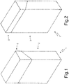
Figure 1 is a front perspective view of a packet of cigarettes provided with two rigid containers, one inside the other, and in a closed configuration; -
Figure 2 is a rear perspective view of the packet of cigarettes inFigure 1 in a closed configuration; -
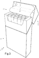
Figure 3 is a front perspective view of the packet of cigarettes inFigure 1 in an open configuration; -
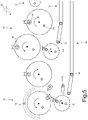
Figure 4 is a frontal schematic view of a packing machine that produces the packet of cigarettes inFigure 1 and is made in accordance with the present invention; -
Figure 5 is an enlarged view of a detail inFigure 4 ; -
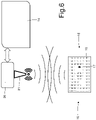
Figure 6 is a schematic view of a transponder and a transmission device of the packing machine inFigure 4 ; -
Figure 7 is a perspective view of a protection casing of the packing machine inFigure 4 ; -
Figures 8-11 are four schematic and sectional views of respective components of the packing machine inFigure 4 , each of which is equipped with a transponder; -
Figure 12 is a schematic view of part of the contents of a programmable memory of the transponder inFigure 6 ; -
Figure 13 is a frontal schematic view of the packing machine inFigure 6 with a localization system highlighted; and -
Figures 14 and15 are two schematic and sectional views of respective components of the packing machine inFigure 13 , each of which is equipped with a transponder and a marker element of the localization system. - In
Figures 1, 2 and3 reference numeral 1 indicates, as a whole, a rigid packet of cigarettes. The packet of cigarettes 1 comprises anouter container 2, which is made of paperboard or cardboard, has an open-box shape, houses aninternal wrapper 3 containing a group ofcigarettes 4, and is provided with ahinged lid 5. - In
Figure 4 ,reference numeral 6 indicates, as a whole, a packing machine that is designed to produce the packet of cigarettes 1. - The
packing machine 6 comprises aframe 7 that stands on the floor and supports aprocessing line 8 along which the processing (i.e. the packing) of the cigarettes (which constitute the product processed by the processing line 8) takes place. The following are arranged along the processing line 8: a formingunit 9 where the groups ofcigarettes 4 are formed in succession, awrapping unit 10 where a wrapping sheet (usually metalized paper) is folded around each group ofcigarettes 4 to form the correspondinginternal wrapper 3, and awrapping unit 11 where a blank (usually cardboard and already provided with pre-weakened fold lines) is folded around eachinternal wrapper 3 to form the correspondingouter container 2 fitted with thehinged lid 5. Afeed unit 12 that feeds the wrapping sheets in succession is coupled to wrappingunit 10 to form theinternal wrappers 3, while afeed unit 13 that feeds the blanks in succession is coupled to wrappingunit 11 to form theouter containers 2. - The
packing machine 6 comprises a plurality of components (for example, linear conveyors, rotary conveyors, gluing machines, fixed and mobile folding machines, control members, support heads, pulleys, belts, pushers, pockets for the groups ofcigarettes 4, electronic circuit boards, electric motors, electric actuators, pneumatic valves, ...),which are distributed along theprocessing line 8 so as to make up the processing line 8 (i.e. to make up the various units 9-13 that form the processing line 8). In particular, each component is stably installed on theframe 7 in a respective predetermined nominal position (i.e. in a predetermined design position in which the component can correctly perform its function). - In addition, the
packing machine 6 comprises acontrol unit 14, which controls the operation of thepacking machine 6 and therefore the processing line. Normally, thecontrol unit 14 is provided with auser interface device 15, which is equipped with a screen and a data input device (keyboard and/or pointing system). - As shown in
Figures 4 and5 , thepacking machine 6 comprises a plurality oftransponders 16, each of which is installed (generally in an inseparable or destructively removable manner) on a corresponding component. Thetransponders 16 can be coupled to any type of component, from larger components (even theframe 7 or the wrapping wheels) to smaller components (gluing machines, support heads installed on the wrapping wheels, pulleys, flexible belts, pockets for the groups ofcigarettes 4, ...). In general, eachtransponder 16 is fastened in an inseparable (or destructively removable) manner to the corresponding component in such a way that in order to remove thetransponder 16 from the component it is necessary to destroy thetransponder 16; in other words, atransponder 16 is never separated from the corresponding component, except in the event of malfunctioning of the transponder 16 (in this case, the oldmalfunctioning transponder 16 is destructively "wrenched" from the component and replaced with a new, correctly functioning transponder 16). - As shown in
Figure 6 , eachtransponder 16 comprises aprogrammable memory 17, designed to contain solely a series of data of the corresponding component, and a wireless (i.e. which exploits electromagnetic waves)transmission device 18, which is designed to send and receive the data contained in theprogrammable memory 17 and comprises, amongst other things, anantenna 19. Theprogrammable memory 17 of eachtransponder 16 is designed to contain solely a series of data of the corresponding component and therefore is not suitable for containing production process data or different data other than the data of the corresponding component. In this regard, it is important to specify that eachtransponder 16 is not connected to any sensor and therefore is not able to receive a reading of any sensor (among other things, the reading of a sensor is a production process datum and therefore could not in any case be stored in theprogrammable memory 17 of a transponder 16). In other words, eachtransponder 16 is an intelligent electronic label, is only capable of radio frequency communication, and is unable of being physically connected (i.e. via a solid connection element such as an electrical copper wire) to any other element for non-radiofrequency communication with the physical element. - According to a preferred embodiment, the
transponders 16 are passive (i.e. without their own electric power source), i.e. they are intelligent electronic labels that (unless equipped with an internal battery) remain "off" until they enter an energy field produced by a reader (when this happens, atransponder 16 becomes charged and starts to transmit its data and, in the absence of an energy field, thetransponder 16 immediately switches off); these types oftransponder 16 are the most inexpensive and are generally able to communicate at distances of less than 10 metres. Alternatively, thetransponders 16 can be semipassive, their method of communication with the reader being identical to that ofpassive transponders 16; in this case, theprogrammable memory 17 is much larger than that of passive transponders and consequently needs a permanent power supply. - As shown in
Figure 6 , thepacking machine 6 comprises a wireless transmission device 20 (i.e. that exploits electromagnetic waves), which is connected to thecontrol unit 14, is designed to communicate with thetransmission device 18 of eachtransponder 16 and is arranged in a fixed position (i.e. installed on theframe 7 of the packing machine 6). In particular,transmission device 20 comprises at least oneantenna 21 that emits and receives radio waves; according to the embodiment shown inFigure 4 , transmission device 20 (schematically shown inFigure 6 ) comprises a plurality (for example three)antennas 21, which are arranged in different positions on theframe 7 of thepacking machine 6 to ensure adequate coverage of theentire packing machine 6. According to a preferred, but non-limitative embodiment,transmission device 20 comprises a single common communications device that, in use, uses thevarious antennas 21 in sequence to dialogue with thetransmission devices 18 of all thetransponders 16 in sequence; in other words, the common communications device connects in sequence with oneantenna 21 at a time to interrogate thetransmission devices 18 of thetransponders 16 of the components located within the working area of thatantenna 21. - Each
transponder 16 is an intelligent electronic label and is only capable of communicating in radio frequency and only in response to an interrogation generated bytransmission device 20; i.e., notransponder 16 can initiate radio frequency communication withtransmission device 20 under its own initiative, but can only respond to an interrogation generated bytransmission device 20. - As shown in
Figure 7 , theautomatic machine 6 comprises a protection casing 22 (shield or case), which is coupled to theautomatic machine 6 to completely cover a front side of theautomatic machine 6, so as to avoid contact with moving parts when theautomatic machine 6 is in operation. Theprotection casing 22 comprisesdoors 23 that are movable between a closed position (shown inFigure 7 ) where access to the front side of theautomatic machine 6 is prevented, and an open position (not shown) where access to the front side of theautomatic machine 6 is permitted; obviously, theautomatic machine 6 can only be set in operation when thedoors 23 of theprotection casing 22 are in the closed position (shown inFigure 7 ). Eachdoor 23 of theprotection casing 22 has at least onewindow 24 fitted with a transparent panel that enables seeing the front side of theautomatic machine 6 even when thedoors 23 of theprotection casing 22 are in the closed position (shown inFigure 7 ). According to a possible embodiment shown inFigure 7 , theantennas 21 of transmission device 20 (schematically shown inFigure 6 ) are installed (fixed) on theprotection casing 22 and, in particular, are installed (fixed) on thedoors 23 of theprotection casing 22 so as to be positioned along the edges of thewindows 24. In other words, theantennas 21 have an annular shape and surroundcorresponding windows 24 of thedoors 23. Alternatively, theantennas 21 could be fixed to thedoors 23 of the protection casing 22 (or also fixed parts of the protection casing 22) next to the windows 24 (i.e. above, below or to the side of the windows 24). In this way, theantennas 21 can be large (consequently with a large range) and can be arranged in close proximity to thetransponders 16 without simultaneously entailing any extra occupied space. - Each
transponder 16 has a flat shape (especially when it is a passive transponder, which is generally shaped like a label). - As shown in
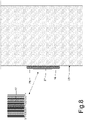
Figure 8 , at least a part of thetransponder 16 is glued directly on theouter surface 25 of the corresponding components, i.e. atransponder 16 is fixed to theouter surface 25 of a corresponding component by the interposition of a permanent glue 26 (generally very strong); this (simpler and inexpensive) solution is preferable when the component is relatively small (i.e. having a size similar to that of the transponder 16) and is made of a plastic material (i.e. a material "transparent" the radio waves), but can still be used in any situation (i.e. even with large and entirely metal components). Thepermanent glue 26 that binds thetransponder 16 to theouter surface 25 of a corresponding component can be applied in a (more or less dense) fluid form or be applied in the form of a double-sided adhesive tape. According to a possible embodiment shown inFigure 8 , the outer surface (i.e. visible from the outside) of thetransponder 16 is provided with anmark 27 that indicates the identification code and/or function of thetransponder 16 in a graphical form (i.e. optically readable). Themark 27 could reproduce the identification code of thetransponder 16 in the form of a bar code, a QR code and/or an alphanumeric code. By way of example, themark 27 could be obtained by ink printing or laser engraving. The function of themark 27 is to enable an operator to optically detect (with their own eyes and/or via an optical reader) the identity and/or function of thetransponder 16. - As shown in
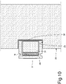
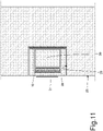
Figures 9 ,10 and11 , in some components, acontainer 28 made of a plastic material (i.e. a material "transparent" to radio waves) is used, which is rigidly connected to the component and internally houses thetransponder 16. Eachcontainer 28 generally has an open-box shape and thus has an open end through which thetransponder 16 is inserted; the open end of eachcontainer 28 is turned to face the inside of the corresponding component so as to be closed by the component itself. According to a preferred, but not limitative embodiment shown inFigures 9 ,10 or11 , the component has ablind hole 29 in which thecontainer 28 is inserted and which partially protrudes outside of theblind hole 29; thetransponder 16 is placed in a part of thecontainer 28 that protrudes outside theblind hole 29 in such a way that thetransponder 16 is located at a certain distance from the component and therefore the transmission of thetransmission device 18 of thetransponder 16 is less disturbed by the presence of the component. Thecontainer 28 can be glued inside theblind hole 29 by a permanent glue 30 (generally very strong); alternatively or in addition, thecontainer 28 could be interference fitted inside the blind hole 29 (i.e. thecontainer 28 is forcefully pushed inside theblind hole 29 causing an elastic or plastic deformation of the container 28). As shown inFigure 9 , the part of thecontainer 28 that protrudes outside theblind hole 29 could have an annular groove to firmly grip thecontainer 28 with pliers or a similar tool and then extract thecontainer 28 from the hole 29 (an operation that generally results in destroying thecontainer 28 and the transponder 16) when it necessary to replace thetransponder 16 housed in thecontainer 28. - To avoid excessively unbalancing a rotating component, two (or more) matching
blind holes 29, symmetrical with respect to the axis of rotation, could be made in the rotating component: oneblind hole 29 is used to house acontainer 28 fitted with atransponder 16, while the other blind hole 29 (which only has a mechanical balancing function) can be left open or filled with anempty container 28. - According to a possible embodiment shown in
Figure 10 , at least onemetal material body 31 is placed inside thecontainer 28 in close proximity to thetransponder 16 for the purposes of increasing the transmission and reception power of thetransmission device 18 of thetransponder 16. In other words, in this embodiment thetransponder 16 is of the "RFID on Metal" type and requires being placed against ametal body 31. - In the alternative embodiment shown in
Figure 11 , thecontainer 28 that houses atransponder 16 is completely inserted in the correspondingblind hole 29 made in a component and therefore does not protrude from theouter surface 25 of the component (i.e. thecontainer 28 is flush with theouter surface 25 of the component). - According to a possible embodiment shown in
Figure 4 , theautomatic machine 6 comprises atemperature sensor 32, which detects the temperature in theautomatic machine 6 and is connected to thecontrol unit 14, and anacceleration sensor 33, which is integral with theframe 7, detects the accelerations to which theframe 7 is subjected and is connected to thecontrol unit 14. According to other embodiments that are not shown, theautomatic machine 6 comprises a different number and/or composition of sensors that are designed to measure a physical quantity (temperature, acceleration, humidity, ...) correlated to the stresses (thermal, mechanical, environmental, ...) to which the components of theprocessing line 8 are subjected; in particular, the sensors could be installed on theframe 7 of the automatic machine 6 (to be common to all the components) or could also be installed on specific components (to be dedicated to the corresponding components). - Each
transponder 16 is paired to a corresponding component of theprocessing line 8 and thememory 17 of eachtransponder 16 contains a series of data related to the component: some of this data is related (as better described hereinafter) to the structure of the component and is therefore never changed or only rarely changed (for example, following overhaul or update operations) while the other data is related to (as better described hereinafter) the operating life of the component (i.e. contains a record of events of the component's operating life) and is therefore cyclically updated (for example, every minute) during operation of theautomatic machine 6. In other words, during operation of theautomatic machine 6, thecontrol unit 14 changes the content of thememory 17 of thetransponder 16, via thetransmission device 20, to update the events of the corresponding component's operating life. - As shown in
Figure 12 , thememory 17 of eachtransponder 16 contains a univocal identifying code IDC of the corresponding component that serves to identify the component with certainty; obviously, this datum is assigned to the component at its time of manufacture and is never changed. - The
memory 17 of eachtransponder 16 contains a version code VS that indicate the version of the corresponding component, i.e. it indicates the update level of the component; this datum is modified following an update operation on the component. - The
memory 17 of eachtransponder 16 contains an univocal identifying code IDCM of the automatic machine 6 (which serves to univocally identify the automatic machine 6) in which the corresponding component is installed; this datum is modified every time the component is installed in a newautomatic machine 6 and indicates the lastautomatic machine 6 where the component was used. In other words, thecontrol unit 14 writes the univocal identifying code IDCM of theautomatic machine 6 in thememory 17 of atransponder 16 when the corresponding component is installed for the first time on theautomatic machine 6. According to a different and perfectly equivalent embodiment, multiple identifying codes IDCM could be provided for storing not only the lastautomatic machine 6 where the component was used, but the last five (ten, fifteen, twenty, ...)automatic machines 6 where the component was used; an hour counter could also be associated with each identifying code IDCM to indicate the component's overall number of hours of use on the correspondingautomatic machine 6. - The
memory 17 of eachtransponder 16 contains a first installation date DTM of the corresponding component on theautomatic machine 6; this datum is modified every time that the component is installed in a newautomatic machine 6 and indicates the date when the component was installed for the first time on the lastautomatic machine 6 where the component was used. In other words, thecontrol unit 14 writes the first installation date DTM in thememory 17 of atransponder 16 when the corresponding component is installed for the first time on theautomatic machine 6. According to a different and perfectly equivalent embodiment, multiple first installation dates DTM could be provided for storing not only the lastautomatic machine 6 where the component was used, but the last five (ten, fifteen, twenty, ...)automatic machines 6 where the component was used. - The
memory 17 of eachtransponder 16 contains a last overhaul date DTO that indicates the last time the corresponding component was subjected to overhaul; this datum is modified following an overhaul operation on the component. - According to a possible, but not limitative embodiment, the
memory 17 of sometransponders 16 contains configuration parameters CF1-CF5 of the corresponding component. These configuration parameters CF1-CF5 indicate the optimal method of using the corresponding component, taking into account the specificity of the component (due to the inevitable constructional tolerances, wear and the past history of the component) and are normally determined experimentally during use of the component. In other words, during the component's usage in theautomatic machine 6, optimal values can be found for the configuration parameters CF1-CF5, which are written to thememory 17 of the correspondingtransponder 16 so they can saved and then reused in the future. Obviously, configuration parameters CF1-CF5 do not exist for all components, but only the more complex ones that have more adjustment possibilities. In use, thecontrol unit 14 reads the optimized values of the configuration parameters CF1-CF5 from thememory 17 of thetransponder 16 of the corresponding component and uses the optimized values to control the component or display the optimized values for manually adjusting the component; in other words, the optimized value of a configuration parameter CF1-CF5 can be used directly by thecontrol unit 14 in the control processes (for example, the temperature to which a hot gluer should be heated, or a corrective value with which to correct a measurement reading, ...) or can be used by an operator for manual adjustment (for example, an angle of inclination at which to set the component, a tightening torque for tightening a screw, ...). - According to a possible, but not limitative embodiment shown in
Figure 12 , thememory 17 of sometransponders 16 contains stress data Tmin, Tmax, Tavg, Smin, Smax and Savg correlated to the physical quantities (temperatures and accelerations in the embodiment shown) measured by thesensors Figure 12 , thememory 17 of sometransponders 16 contains the minimum temperature Tmin, the maximum temperature Tmax and the average temperature Tavg at which the corresponding component has operated, and also contains the minimum acceleration level Smin (vibrations), maximum acceleration level Smax (vibrations), and average acceleration level Savg (vibrations) at which the corresponding component has operated. In use, thecontrol unit 14 cyclically reads thesensors memory 17 of eachtransponder 16. - As previously mentioned, the
sensors entire packing machine 6 and are therefore installed on theframe 7 of the packingmachine 6, or can be specific for one component (or a limited group of components) and are therefore installed on a component; typically, thetemperature sensor 32 is related to theentire packing machine 6 as the ambient temperature between nearby components does not vary significantly, while theacceleration sensor 33 can be related to a specific component (i.e. a number ofdifferent acceleration sensors 33 can be provided) as the acceleration level (vibrations) can change significantly from component to component. - According to a possible, but not limitative embodiment shown in
Figure 12 , thememory 17 of sometransponders 16 contains a plurality of stress counters SC10-SC100 indicating the actual working time of the corresponding component at different values taken by the physical quantity measured by thetemperature sensor 32 or theacceleration sensor 33; in the example shown inFigure 12 , ten stress counters SC10-SC100 are provided, indicating the actual working time (normally measured in hours) of the corresponding component at 10%, 20%, 30%, ..., 90% and 100% of the maximum stress. According to a possible embodiment shown inFigure 12 , an equivalent stress counter SCeqv is also provided, which contains a value calculated, for example, by means of a linear combination of the ten stress counters SC10-SC100 (with obviously different weights) and constitutes an equivalent working time (normally measured in hours) of the component that takes into account the effective stress to which the component was subjected during use; obviously, in the calculation of the equivalent stress counter SCeqv, the actual working time at low stress levels (i.e. stress counters SC10-S30) counts less than the actual working time at high stress levels (i.e. stress counters SC70-SC100), while the weights with which the ten stress counters SC10-SC100 are combined are generally determined from theoretical calculations and, if necessary, experimentally refined (i.e. by means of experimental verification). - It is clear that the stress counters SC10-SC100 can be useful for certain components that are more complex (therefore high-cost) and more stress sensitive, while they are not useful for other components that are simpler (therefore low-cost) and less stress sensitive; in addition, some components might be more sensitive to mechanical stress (and so it makes sense to keep track of the accelerations measured by the acceleration sensor 33) while other components might be more sensitive to heat stress (and so it makes sense to keep track of the temperatures measured by the temperature sensor 32). According to the embodiment shown in
Figure 12 , the memory - 17 of each
transponder 16 contains an additional use counter UC indicating the actual working time (normally measured in hours) of the corresponding component; in use, when theprocessing line 8 is working to process the products (i.e. the groups of cigarettes 4), thecontrol unit 14 cyclically modifies the content of thememory 17 of eachtransponder 16 to increase the additional use counter UC of the corresponding component. - According to a possible, but not limitative embodiment shown in
Figure 12 , thememory 17 of eachtransponder 16 contains an equivalent use counter UCeqv1 that indicates the equivalent working time (normally measured in hours) of the corresponding component and is increased not with the actual operating time (unlike the use counter UC), but with an equivalent operating time that is established depending on the actual operating speed of the packingmachine 6. In other words, a nominal operating speed is provided that represents the maximum operating speed achievable by the processing line 8 (i.e. by the packing machine 6) and thecontrol unit 14 is designed to determine an actual operating speed at which the processing line 8 (i.e. the automatic machine 6) is working; thecontrol unit 14 increases the equivalent use counter UCeqv1 of the corresponding component by an amount that depends on the elapsed amount of time and the ratio between the actual operating speed and the nominal operating speed. For example, thecontrol unit 14 determines a wear factor that depends on the actual operating speed and increases the equivalent use counter UCeqv1 of the corresponding component by an amount equal to the product of the elapsed amount of time and the wear factor (i.e. the lower the actual operating speed, the lower the increase in the equivalent use counter UCeqv1 for the same elapsed operating time). - As shown in
Figure 12 , eventually in combination with the equivalent use counter UCeqv1, thememory 17 of thetransponders 16 contains a plurality of use counters UC10-UC100 indicating the actual working time (normally measured in hours) of the corresponding component at different operating speeds ranging from zero to the nominal operating speed, wherein the nominal operating speed represents the maximum operating speed that can be reached by the processing line. In the example inFigure 12 , ten use counters UC10-UC100 are provided indicating the actual working time (normally measured in hours) of the corresponding component at 10%, 20%, 30%, ..., 90% and 100% of the nominal operating speed. According to a possible embodiment shown inFigure 12 , an equivalent use counter UCeqv2 is also provided that contains a value calculated, for example, by means of a linear combination of the ten use counters UC10-UC100 (with obviously different weights) and constitutes an equivalent working time (normally measured in hours) of the component that takes into account the actual operating speeds maintained by the component during use; obviously, in the calculation of the equivalent use counter UCeqv2, the actual working time at low operating speeds (i.e. use counters UC10-S30) counts less than the actual working time at high operating speeds (i.e. use counters UC70-UC100), while the weights with which the ten use counters UC10-UC100 are combined are generally determined from theoretical calculations and, if necessary, experimentally refined (i.e. by means of experimental verification). - According to a possible, but not limitative embodiment shown in
Figure 12 , thememory 17 of eachtransponder 16 contains a position code PSTN that indicates the actual position of the corresponding component inside the packingmachine 6, i.e. it indicates where the corresponding component is located inside the packingmachine 6. - The position code PSTN is generally used for all components that can be installed in different positions on the
packing machine 6. For example, the packingmachine 6 could use three identical gluing devices that are installed in three different positions and it is evident that each gluing device could be indifferently installed in each of the three different positions; in this case, the position code PSTN indicates in which of the three different positions a certain gluing device is effectively installed. For example, each wrapping wheel of the packingmachine 6 comprises a plurality of matching heads (for example, from six to sixteen heads for each wrapping wheel) and a head can be installed in series of different positions in a wrapping wheel; in this case, the position code PSTN indicates in which position (forexample position machine 6 could use a series of identical electric motors that are installed in different positions and it is evident that each electric motor could be indifferently installed in each of the possible different positions; in this case, the position code PSTN indicates in which of the possible different positions a certain electric motor has effectively been installed. The knowledge of the exact position of a certain component in the packing machine 6 (obviously when the component is installable in at least two different positions) enables checking whether the component is subjected to the same type of wear or to differential wear when it is installed in different positions. - The position code PSTN is, in general, also used for all the (generally small) components that can be installed on the
packing machine 6 in incorrect positions, for example by (erroneously) exchanging the position of two components. For example, a panel intended to stay on the left of a path could be (erroneously) installed on the right and vice versa. - The position code PSTN is not generally used (i.e. it is ignored) for all the components that can only be installed on the
packing machine 6 in a single position and (due to their size and/or shape) cannot be (erroneously) installed in a wrong position (i.e. in a position other than the correct position, which is the predetermined nominal position). For example, each wrapping wheel of the packingmachine 6 can normally only be installed in one position and therefore there is no possibility of a wrapping wheel of the packingmachine 6 being installed in a different position from that planned (i.e. from the predetermined nominal position); furthermore, it is not possible for a wrapping wheel to be installed in the wrong position as it is generally physically impossible to install a wrapping wheel in a different position from that planned. - According to one possible embodiment, the position of a given component is "manually" entered by an operator (normally, the operator who installed the component on the packing machine 6); in other words, after installing the component on the
packing machine 6, the operator communicates the actual position of the component to the control unit 14 (generally via the user interface device 15) and thecontrol unit 14 writes this position in thememory 17 of the corresponding transponder 16 (in particular, in the position code PSTN contained in the memory 17). Obviously, this operation is only performed for components that could be installed on thepacking machine 6 in different or incorrect positions. In this case, at the end of an operator's intervention, thecontrol unit 14 could automatically determine the presence of a new component through the correspondingtransponder 16 and, if the information is considered useful, could request the operator to enter the actual position of the component in thepacking machine 6 before enabling the starting of the packingmachine 6. - According to a different embodiment shown in
Figure 12 , the position of some components in thepacking machine 6 is not "manually" entered by an operator, but is automatically determined by anelectronic localization system 34 connected to thecontrol unit 14. - The
localization system 34 comprises a plurality ofmarker elements 35 that are coupled (fixed) to corresponding components for which it is wished to determine the actual position (which is only different from the predetermined nominal position in the case of error) inside the packingmachine 6. In addition, thelocalization system 34 comprises (at least) oneinterrogation device 36 that is placed in a fixed position, is connected to thecontrol unit 14, and is designed to determine an actual position of eachmarker element 35, i.e. an actual position of the component provided with themarker element 35. Theinterrogation device 36 comprises antennas that are generally small (unlike theantenna 21 of the transmission device 20) and that, if necessary, can be connected to theprotection casing 22 of the packingmachine 6 in a similarly manner to theantenna 21 of thetransmission device 20. - According to a preferred embodiment, the
control unit 14 stores the actual position of a component provided with amarker element 35 in its memory and, at the same time, writes the actual position of the component provided with themarker element 35 in thememory 17 of the corresponding transponder 16 (i.e. in the position code PSTN contained in the memory 17). All of this takes place automatically, as the actual position of components provided with marker elements 35 (i.e. components for which it is effectively useful to determine the actual position) is determined by thecontrol unit 14 using thelocalization system 34 and therefore without the need for operation intervention. - According to a preferred embodiment, the
control unit 14 checks whether the actual position of each component provided with amarker element 35 corresponds to a desired position for the component (i.e. whether or not the actual position is the same as the desired position); in consequence, thecontrol unit 14 generates an error signal if the actual position of a component provided with amarker element 35 does not correspond to the desired position of the component. In this way, thecontrol unit 14 is able to autonomously determine whether there are any improperly positioned components. - According to a possible, but not limitative embodiment shown in
Figure 14 , eachmarker element 35 is arranged together with the correspondingtransponder 16 on a single shared support; for example eachmarker element 35 is arranged in thesame container 28 that contains thetransponder 16 associated with the same component. Alternatively, and as shown inFigure 15 , in a same component themarker element 35 is completely independent of thetransponder 16, i.e. themarker element 35 is fixed to the component at a certain distance from and independently of thetransponder 16 - According to a preferred, but not limitative embodiment, the
localization system 34 uses "Ultra Wide Band" (UWB) technology to implement communications between themarker element 35 and theinterrogation device 36; UWB technology derives its name from the ability to exploit a wide range of frequencies, ranging between 3.1 and 10 gigahertz and thus with a bandwidth of approximately 7 gigahertz. Invented and designed for short-distance data exchange, UWB technology bases its operation on the exchange of digital pulses between source and receivers at extremely regular time intervals. What makes the difference between UWB technology and other wireless data exchange technologies is substantially the timing: the synchronization between the node that sends the signal and the nodes that receive it must have an accuracy of a few trillionths of a second; in consequence, UWB systems are able to measure the "transit time" of information with extreme precision, and this enables calculating the distance that separates the antenna that transmits the signal from the antenna that receives it with a margin of centimetres (if not millimetres). Furthermore, UWB technology is virtually indistinguishable from so-called "background noise": in fact, signal power is always very low at all the frequencies used by UWB technology, (current usage is limited to a few tenths of a watt); in consequence, UWB technology does not interfere in any way with data transmissions between thetransmission device 20 and thetransponders 16, and does not suffer interference from data transmissions betweentransmission device 20 and thetransponders 16. In this way, thelocalization system 34 can coexist with thetransmission devices - It is important to note that the
localization system 34 is not normally always active (the components do not change their position without operator intervention, which is only possible when the packingmachine 6 is stopped), but is activated only when needed, i.e. only when the configuration of the packingmachine 6 might have been changed; for example, thelocalization system 34 could be activated for a brief moment every time thepacking machine 6 is restarted after a machine stop during which theprotection casing 22 was at least partially open. In consequence, when thelocalization system 34 is activated, communication between thecontrol unit 14 and thetransponders 16 could be temporarily interrupted as a precaution. - According to one possible embodiment,
transponders 16 and/ormarker elements 35 could also be associated with tools and equipment used to carry out technical operations on thepacking machine 6; in this way, thecontrol unit 14 can check, before starting thepacking machine 6, that no tools or equipment have been "forgotten" inside packingmachine 6. - According to a preferred embodiment, the
control unit 14 signals the need for a cleaning/maintenance/overhaul/replacement operation on a component of theprocessing line 8 depending on the data stored in thememory 17 of the correspondingtransponder 16. To determine the need for a cleaning/maintenance/overhaul/replacement operation on a component, thecontrol unit 14 takes into account all the data contained in thememory 17 of the correspondingtransponder 16 and related to the events of the corresponding component's operating life; obviously, greater importance is given to the use counter UC indicating the actual working time (normally measured in hours) of the corresponding component, but all the other data is also taken into due account in cases where the component has been less stressed or more stressed than average. - According to one possible embodiment, the
control unit 14 cyclically reads some or all of the data contained in thememories 17 of all thetransponders 16, stores this data in a local mass storage device (typically a hard disk or a solid-state memory), and also transmits this data to a remote server of the manufacturer of theautomatic machine 6. In this way, by collecting the data originating from all theautomatic machines 6 installed worldwide, the manufacturer of theautomatic machine 6 can perform largescale statistical processing that enables optimizing predictive maintenance of the automatic machines 6 (predictive maintenance is a type of preventive maintenance that is carried out following the identification of one or more parameters that are measured and extrapolated using appropriate mathematical models in order to identify the residual time before a fault). Furthermore, in this way, the manufacturer of theautomatic machine 6 can know the actual composition of eachautomatic machine 6 installed around the world in real time, i.e. know exactly all the components that are currently installed (and therefore operating) on eachautomatic machine 6 installed around the world, and therefore be able to program the production of spare parts with greater confidence and also check that all the components that are currently installed (and therefore operating) on eachautomatic machine 6 installed around the world are completely compatible with one another (not so much as components in themselves, but rather the versions of the components; for example, version X of a component might not be fully compatible with version Y of another component). - In the embodiment shown in the accompanying figures, the
automatic machine 6 is a packing machine that produces packets of cigarettes 1; according to other perfectly equivalent embodiments that are not shown, theautomatic machine 6 could be a cigarette making machine, a cigarette filter making machine, a packing machine that applies a transparent outer wrapper to cigarette packs, a packing machine that produces cartons of cigarette packs, a cartoning machine, a packing machine that produces foodstuff packages, a sanitary towels making machine, a packing machine for sanitary towels, etc. In other words, the products processed by the packing machine are constituted by smoking, sanitary, foodstuff, or pharmaceutical products. - The above-described
automatic machine 6 has numerous advantages. - First of all, the above-described
automatic machine 6 enables programming the maintenance of all its components in an extremely precise and reliable manner, independently of whether some components are installed on and/or removed from theautomatic machine 6 at each format change. - Furthermore, the above-described
automatic machine 6 is simple and inexpensive to manufacture as it uses low-cost and readily available commercial components (thetransponders 16 constituted by passive transponders for example).
Claims (16)
- An automatic machine (6) for the production or packaging of smoking, sanitary, foodstuff, or pharmaceutical products; the automatic machine (6) comprises:at least one processing line (8), along which the products are processed;a plurality of components, which are distributed along the processing line (8) so as to make up the processing line (8) ;at least one transponder (16), which is mounted on a corresponding component, comprises a programmable memory (17) designed to contain solely a series of data of the component, and comprises a first transmission device (18), which is designed to send and receive the data contained in the programmable memory (17);a second transmission device (20), which is designed to communicate with the first transmission device (18); anda control unit (14), configured to control the operation of the automatic machine (6) and is connected to the second transmission device (20);wherein the memory (17) of the transponder (16) contains a univocal identifying code (IDC) of the corresponding component; andwherein a nominal operating speed is provided, which represents the maximum operating speed that can be reached by the processing line (8);the automatic machine is characterized in that:the memory (17) of the transponder (16) contains a record of events of the operating life of the corresponding component; the control unit (14) is designed to change, through the second transmission device (20), the content of the memory (17) of the transponder (16) so as to update the events of the operating life of the corresponding component; andthe memory (17) of the transponder (16) contains a plurality of use counters (UC10-UC100) indicating the actual working time of the corresponding component at different operating speeds ranging from zero to the nominal operating speed.
- The automatic machine (6) according to claim 1, wherein:the memory (17) of the transponder (16) contains an additional use counter (UC) indicating the actual working time of the corresponding component; andthe control unit (14) is configured to cyclically change, when the processing line (8) is working to process the products, the content of the memory (17) of the transponder (16) so as to increase the additional use counter (UC) of the corresponding component
- The automatic machine (6) according to claim 1 or 2, wherein:the control unit (14) is designed to determine an actual operating speed at which the processing line (8) is working;the memory (17) of the transponder (16) contains a first equivalent use counter (UCeqv1); andthe control unit (14) is configured to increase the first equivalent use counter (UCeqv1) of the corresponding component by a quantity that depends on the elapsed amount of time and on the ratio between the actual operating speed and the nominal operating speed.
- The automatic machine (6) according to claim 3, wherein the control unit (14) is configured to determine a wear factor depending on the actual operating speed and is configured to increase the first equivalent use counter (UCeqv1) of the corresponding component by a quantity that is equal to the product of the elapsed amount of time and the wear factor.
- The automatic machine (6) according to one of the claims from 1 to 4, wherein the control unit (14) is configured to determine the need for a cleaning / maintenance / overhaul / replacement operation to be carried out on a component of the processing line (8) depending on the data stored in the memory (17) of the corresponding transponder (16).
- The automatic machine (6) according to one of the claims from 1 to 5, wherein:at least one sensor (32, 33) is provided, which is designed to measure a physical quantity correlated with the stresses to which the corresponding component is subjected;the memory (17) of the transponder (16) contains at least one stress datum (Tmin, Tmax, Tavg, Smin, Smax, Savg), which is correlated with the physical quantity measured by the sensor (32, 33); andthe control unit (14) is configured to cyclically read the sensor (32, 33) and, if necessary, updates the stress datum (Tmin, Tmax, Tavg, Smin, Smax, Savg) of the memory (17) of the transponder (16) .
- The automatic machine (6) according to claim 6, wherein the memory (17) of the transponder (16) contains a plurality of stress counters (SC10-SC100) indicating the actual working time of the corresponding component at different values taken by the physical quantity measured by the sensor (32, 33).
- The automatic machine (6) according to one of the claims from 1 to 7, wherein:the memory (17) of the transponder (16) contains at least one configuration parameter (CF1-CF5) of the corresponding component; andthe control unit (14) is configured to read, from the memory (17) of the transponder (16), an optimized value of the configuration parameter (CF1-CF5) of the corresponding component and is configured to use the optimized value to control the component or to display the optimized values for manual set-up of the components.
- The automatic machine (6) according to one of the claims from 1 to 8, wherein:the memory (17) of the transponder (16) contains a first installation date (DTM) of the corresponding component in the automatic machine (6); andthe control unit (14) is configured to write the first installation date (DTM) in the memory (17) of the transponder (16) when the corresponding component is installed for the first time in the automatic machine (6).
- The automatic machine (6) according to one of the claims from 1 to 9, wherein:the memory (17) of the transponder (16) contains a univocal identifying code (IDCM) of the automatic machine (6); andthe control unit (14) is configured to write the univocal identifying code (IDCM) of the automatic machine (6) in the memory (17) of the transponder (16) when the corresponding component is installed for the first time in the automatic machine (6).
- The automatic machine (6) according to one of the claims from 1 to 10, wherein the memory (17) of the transponder (16) contains a last overhaul date (DTO).
- The automatic machine (6) according to one of the claims from 1 to 11, wherein the memory (17) of the transponder (16) contains a code (VS) indicating the version of the corresponding component.
- The automatic machine (6) according to one of the claims from 1 to 12, wherein the memory (17) of the transponder (16) contains a position code (PSTN), which indicates the position of the corresponding component inside the automatic machine (6).
- The automatic machine (6) according to one of the claims from 1 to 13, wherein:it is provided a plastic material container (28), which is rigidly connected to the component and internally houses the transponder (16);the component has a blind hole (29) where the container (28) is inserted so as to partially protrude from the blind hole (29); andthe transponder (16) is arranged in a part of the container (28) that protrudes from the blind hole (29).
- The automatic machine (6) according to one of the claims from 1 to 14 and comprising a plastic material container (28), which is rigidly connected to the component, internally houses the transponder (16), and houses also at least one metal material body (31) arranged close to the transponder (16) .
- A method to control an automatic machine (6) for the production or packaging of smoking, sanitary, foodstuff, or pharmaceutical products;the automatic machine (6) comprises: at least one processing line (8), along which the products are processed, a plurality of components, which are distributed along the processing line (8) so as to make up the processing line (8), and a control unit (14), which controls the operation of the automatic machine (6);the control method comprises the step of associating at least one component with a transponder (16), which is mounted on the component, comprises a programmable memory (17) designed to contain solely a series of data of the component, and comprises a first transmission device (18), which is designed to send and receive the data contained in the programmable memory (17);wherein the data contained in the memory (17) of the transponder (16) comprise a univocal identifying code (IDC) of the corresponding component;wherein a second transmission device (20) is provided, which is designed to communicate with the first transmission device (18) and is connected to the control unit (14); and wherein a nominal operating speed is provided, which represents the maximum operating speed that can be reached by the processing line (8);the control method is characterized in that:the memory (17) of the transponder (16) contains a record of events of the operating life of the corresponding component;the control method comprises the further step of changing, by means of the control unit (14) and through the second transmission device (20), the content of the memory (17) of the transponder (16) so as to update the events of the operating life of the corresponding component; andthe memory (17) of the transponder (16) contains a plurality of use counters (UC10-UC100) indicating the actual working time of the corresponding component at different operating speeds ranging from zero to the nominal operating speed.
Applications Claiming Priority (2)
| Application Number | Priority Date | Filing Date | Title |
|---|---|---|---|
| IT201800002485A IT201800002485A1 (en) | 2018-02-08 | 2018-02-08 | Automatic product processing machine and corresponding control method |
| PCT/IB2019/051036 WO2019155420A1 (en) | 2018-02-08 | 2019-02-08 | Automatic machine for the production or packaging of smoking, sanitary, foodstuff, or pharmaceutical products and corresponding control method |
Publications (2)
| Publication Number | Publication Date |
|---|---|
| EP3750015A1 EP3750015A1 (en) | 2020-12-16 |
| EP3750015B1 true EP3750015B1 (en) | 2022-08-17 |
Family
ID=62089965
Family Applications (1)
| Application Number | Title | Priority Date | Filing Date |
|---|---|---|---|
| EP19709122.6A Active EP3750015B1 (en) | 2018-02-08 | 2019-02-08 | Automatic machine for the production or packaging of smoking, sanitary, foodstuff, or pharmaceutical products and corresponding control method |
Country Status (4)
| Country | Link |
|---|---|
| EP (1) | EP3750015B1 (en) |
| IT (1) | IT201800002485A1 (en) |
| PL (1) | PL3750015T3 (en) |
| WO (1) | WO2019155420A1 (en) |
Families Citing this family (2)
| Publication number | Priority date | Publication date | Assignee | Title |
|---|---|---|---|---|
| IT201900019852A1 (en) * | 2019-10-28 | 2021-04-28 | Gd Spa | Assistance method for the execution of a format change in an automatic machine for the production or packaging of smoking, hygiene, food, or pharmaceutical products and corresponding automatic machine |
| CN117429662B (en) * | 2023-11-27 | 2025-11-18 | 红云红河烟草(集团)有限责任公司 | A method and device for automatic loading and control of irregularly shaped cigarette packs |
Citations (6)
| Publication number | Priority date | Publication date | Assignee | Title |
|---|---|---|---|---|
| WO2003071880A2 (en) | 2002-02-27 | 2003-09-04 | Landucci S.R.L. | System for automated management of dies, moulds and the like in a pasta factory |
| US20060129269A1 (en) | 2004-12-15 | 2006-06-15 | Xerox Corporation | Processes for using a memory storage device in conjunction with tooling |
| EP1734428A2 (en) | 2005-05-16 | 2006-12-20 | Circuitmaster Designs Limited | A system for monitoring and controlling operation of a machine having a detachable component |
| EP2690516A1 (en) | 2011-03-22 | 2014-01-29 | NTN Corporation | Method for diagnosing reusability of mechanical component |
| WO2015166349A1 (en) | 2014-04-29 | 2015-11-05 | Aktiebolaget Skf | Trending machine health data using rfid transponders |
| WO2016087028A1 (en) | 2014-12-03 | 2016-06-09 | Dürr Systems GmbH | Application system component with transponder and/or wear detection device |
Family Cites Families (6)
| Publication number | Priority date | Publication date | Assignee | Title |
|---|---|---|---|---|
| CA2401161C (en) * | 2000-02-29 | 2006-10-03 | Pcc Specialty Products, Inc. | Smart machine tool system |
| US6351621B1 (en) * | 2000-06-26 | 2002-02-26 | Xerox Corporation | Wireless interaction with memory associated with a replaceable module for office equipment |
| ITBO20030704A1 (en) * | 2003-11-21 | 2005-05-22 | Gd Spa | AUTOMATIC MACHINE FOR THE PROCESSING OF SMOKE ITEMS. |
| JP2012069733A (en) * | 2010-09-24 | 2012-04-05 | Hitachi High-Tech Instruments Co Ltd | Tooling management method of die bonder, and die bonder |
| KR101461908B1 (en) * | 2013-08-12 | 2014-11-13 | 현대자동차주식회사 | Joint guarantee system for vehicle assembly and control method of the same |
| US9589287B2 (en) * | 2015-06-29 | 2017-03-07 | Miq Llc | User community generated analytics and marketplace data for modular systems |
-
2018
- 2018-02-08 IT IT201800002485A patent/IT201800002485A1/en unknown
-
2019
- 2019-02-08 PL PL19709122.6T patent/PL3750015T3/en unknown
- 2019-02-08 EP EP19709122.6A patent/EP3750015B1/en active Active
- 2019-02-08 WO PCT/IB2019/051036 patent/WO2019155420A1/en not_active Ceased
Patent Citations (6)
| Publication number | Priority date | Publication date | Assignee | Title |
|---|---|---|---|---|
| WO2003071880A2 (en) | 2002-02-27 | 2003-09-04 | Landucci S.R.L. | System for automated management of dies, moulds and the like in a pasta factory |
| US20060129269A1 (en) | 2004-12-15 | 2006-06-15 | Xerox Corporation | Processes for using a memory storage device in conjunction with tooling |
| EP1734428A2 (en) | 2005-05-16 | 2006-12-20 | Circuitmaster Designs Limited | A system for monitoring and controlling operation of a machine having a detachable component |
| EP2690516A1 (en) | 2011-03-22 | 2014-01-29 | NTN Corporation | Method for diagnosing reusability of mechanical component |
| WO2015166349A1 (en) | 2014-04-29 | 2015-11-05 | Aktiebolaget Skf | Trending machine health data using rfid transponders |
| WO2016087028A1 (en) | 2014-12-03 | 2016-06-09 | Dürr Systems GmbH | Application system component with transponder and/or wear detection device |
Also Published As
| Publication number | Publication date |
|---|---|
| IT201800002485A1 (en) | 2019-08-08 |
| EP3750015A1 (en) | 2020-12-16 |
| WO2019155420A1 (en) | 2019-08-15 |
| PL3750015T3 (en) | 2022-11-21 |
Similar Documents
| Publication | Publication Date | Title |
|---|---|---|
| CN101279652B (en) | System and method for producing and packaging tobacco articles | |
| EP3750015B1 (en) | Automatic machine for the production or packaging of smoking, sanitary, foodstuff, or pharmaceutical products and corresponding control method | |
| EP3750013B1 (en) | Automatic machine for the processing of products and corresponding control method | |
| US7669387B2 (en) | Package particularly a cigarette package, and method and device for the production thereof | |
| EP1266830A1 (en) | Method and system for identifying packaging material on a packaging machine | |
| BR0308259B1 (en) | MANUFACTURING AND PACKAGING INSTALLATION | |
| EP1872951B1 (en) | Cartridge collecting apparatus | |
| CN115336187B (en) | Method for transmitting data in a linear transport system and linear transport system | |
| US20090314829A1 (en) | Systems, Methods, and Devices for Replication of Data onto Wireless Sensors | |
| WO2019155422A1 (en) | Automatic machine for the production or packaging of smoking, sanitary, foodstuff, or pharmaceutical products and corresponding control method | |
| KR102831170B1 (en) | Tool inserts for machines, machines and methods for operating machines | |
| JP5015492B2 (en) | Rebranding method in automatic production equipment for processing tobacco products | |
| EP4052106B1 (en) | Assistance method for the execution of a format change in an automatic machine for manufacturing or packing smoking, hygiene, food, or pharmaceutical products and respective automatic machine | |
| US7461495B2 (en) | Packaging control with translation of command protocols | |
| EP3501300B1 (en) | Production line in the tobacco industry and method for inspecting it | |
| JP5969009B2 (en) | How to operate a plant that produces tablets | |
| JP2020504368A (en) | Apparatus with RFID tag for monitoring storage and / or transportation status of articles and related methods | |
| RU2823546C1 (en) | Method of ensuring format change in automatic machine for manufacture or packaging of smoking, hygienic, food or pharmaceutical products and corresponding automatic machine | |
| US11738581B2 (en) | Print head marking | |
| KR101453289B1 (en) | Apparatus and method of attaching identification tag for box | |
| JP2004050678A (en) | Consumables, consumables management system and management method | |
| JPWO2021084437A5 (en) |
Legal Events
| Date | Code | Title | Description |
|---|---|---|---|
| STAA | Information on the status of an ep patent application or granted ep patent |
Free format text: STATUS: UNKNOWN |
|
| STAA | Information on the status of an ep patent application or granted ep patent |
Free format text: STATUS: THE INTERNATIONAL PUBLICATION HAS BEEN MADE |
|
| PUAI | Public reference made under article 153(3) epc to a published international application that has entered the european phase |
Free format text: ORIGINAL CODE: 0009012 |
|
| STAA | Information on the status of an ep patent application or granted ep patent |
Free format text: STATUS: REQUEST FOR EXAMINATION WAS MADE |
|
| 17P | Request for examination filed |
Effective date: 20200805 |
|
| AK | Designated contracting states |
Kind code of ref document: A1 Designated state(s): AL AT BE BG CH CY CZ DE DK EE ES FI FR GB GR HR HU IE IS IT LI LT LU LV MC MK MT NL NO PL PT RO RS SE SI SK SM TR |
|
| AX | Request for extension of the european patent |
Extension state: BA ME |
|
| RIN1 | Information on inventor provided before grant (corrected) |
Inventor name: BARBACCIA, VINCENZO Inventor name: FEDERICI, LUCA Inventor name: BERGONZONI, TIZIANA Inventor name: BAGOLINI, PAOLO Inventor name: MARTIGNANI, DAVIDE |
|
| DAV | Request for validation of the european patent (deleted) | ||
| DAX | Request for extension of the european patent (deleted) | ||
| GRAP | Despatch of communication of intention to grant a patent |
Free format text: ORIGINAL CODE: EPIDOSNIGR1 |
|
| STAA | Information on the status of an ep patent application or granted ep patent |
Free format text: STATUS: GRANT OF PATENT IS INTENDED |
|
| INTG | Intention to grant announced |
Effective date: 20220301 |
|
| GRAS | Grant fee paid |
Free format text: ORIGINAL CODE: EPIDOSNIGR3 |
|
| GRAA | (expected) grant |
Free format text: ORIGINAL CODE: 0009210 |
|
| STAA | Information on the status of an ep patent application or granted ep patent |
Free format text: STATUS: THE PATENT HAS BEEN GRANTED |
|
| AK | Designated contracting states |
Kind code of ref document: B1 Designated state(s): AL AT BE BG CH CY CZ DE DK EE ES FI FR GB GR HR HU IE IS IT LI LT LU LV MC MK MT NL NO PL PT RO RS SE SI SK SM TR |
|
| REG | Reference to a national code |
Ref country code: CH Ref legal event code: EP |
|
| REG | Reference to a national code |
Ref country code: DE Ref legal event code: R096 Ref document number: 602019018367 Country of ref document: DE |
|
| REG | Reference to a national code |
Ref country code: IE Ref legal event code: FG4D |
|
| REG | Reference to a national code |
Ref country code: AT Ref legal event code: REF Ref document number: 1512581 Country of ref document: AT Kind code of ref document: T Effective date: 20220915 |
|
| REG | Reference to a national code |
Ref country code: NL Ref legal event code: MP Effective date: 20220817 |
|
| REG | Reference to a national code |
Ref country code: LT Ref legal event code: MG9D |
|
| PG25 | Lapsed in a contracting state [announced via postgrant information from national office to epo] |
Ref country code: SE Free format text: LAPSE BECAUSE OF FAILURE TO SUBMIT A TRANSLATION OF THE DESCRIPTION OR TO PAY THE FEE WITHIN THE PRESCRIBED TIME-LIMIT Effective date: 20220817 Ref country code: RS Free format text: LAPSE BECAUSE OF FAILURE TO SUBMIT A TRANSLATION OF THE DESCRIPTION OR TO PAY THE FEE WITHIN THE PRESCRIBED TIME-LIMIT Effective date: 20220817 Ref country code: PT Free format text: LAPSE BECAUSE OF FAILURE TO SUBMIT A TRANSLATION OF THE DESCRIPTION OR TO PAY THE FEE WITHIN THE PRESCRIBED TIME-LIMIT Effective date: 20221219 Ref country code: NO Free format text: LAPSE BECAUSE OF FAILURE TO SUBMIT A TRANSLATION OF THE DESCRIPTION OR TO PAY THE FEE WITHIN THE PRESCRIBED TIME-LIMIT Effective date: 20221117 Ref country code: NL Free format text: LAPSE BECAUSE OF FAILURE TO SUBMIT A TRANSLATION OF THE DESCRIPTION OR TO PAY THE FEE WITHIN THE PRESCRIBED TIME-LIMIT Effective date: 20220817 Ref country code: LV Free format text: LAPSE BECAUSE OF FAILURE TO SUBMIT A TRANSLATION OF THE DESCRIPTION OR TO PAY THE FEE WITHIN THE PRESCRIBED TIME-LIMIT Effective date: 20220817 Ref country code: LT Free format text: LAPSE BECAUSE OF FAILURE TO SUBMIT A TRANSLATION OF THE DESCRIPTION OR TO PAY THE FEE WITHIN THE PRESCRIBED TIME-LIMIT Effective date: 20220817 Ref country code: FI Free format text: LAPSE BECAUSE OF FAILURE TO SUBMIT A TRANSLATION OF THE DESCRIPTION OR TO PAY THE FEE WITHIN THE PRESCRIBED TIME-LIMIT Effective date: 20220817 |
|
| REG | Reference to a national code |
Ref country code: AT Ref legal event code: MK05 Ref document number: 1512581 Country of ref document: AT Kind code of ref document: T Effective date: 20220817 |
|
| PG25 | Lapsed in a contracting state [announced via postgrant information from national office to epo] |
Ref country code: IS Free format text: LAPSE BECAUSE OF FAILURE TO SUBMIT A TRANSLATION OF THE DESCRIPTION OR TO PAY THE FEE WITHIN THE PRESCRIBED TIME-LIMIT Effective date: 20221217 Ref country code: HR Free format text: LAPSE BECAUSE OF FAILURE TO SUBMIT A TRANSLATION OF THE DESCRIPTION OR TO PAY THE FEE WITHIN THE PRESCRIBED TIME-LIMIT Effective date: 20220817 Ref country code: GR Free format text: LAPSE BECAUSE OF FAILURE TO SUBMIT A TRANSLATION OF THE DESCRIPTION OR TO PAY THE FEE WITHIN THE PRESCRIBED TIME-LIMIT Effective date: 20221118 |
|
| REG | Reference to a national code |
Ref country code: DE Ref legal event code: R026 Ref document number: 602019018367 Country of ref document: DE |
|
| PLBI | Opposition filed |
Free format text: ORIGINAL CODE: 0009260 |
|
| 26 | Opposition filed |
Opponent name: FOCKE & CO. (GMBH & CO. KG) Effective date: 20230322 |
|
| PG25 | Lapsed in a contracting state [announced via postgrant information from national office to epo] |
Ref country code: SM Free format text: LAPSE BECAUSE OF FAILURE TO SUBMIT A TRANSLATION OF THE DESCRIPTION OR TO PAY THE FEE WITHIN THE PRESCRIBED TIME-LIMIT Effective date: 20220817 Ref country code: RO Free format text: LAPSE BECAUSE OF FAILURE TO SUBMIT A TRANSLATION OF THE DESCRIPTION OR TO PAY THE FEE WITHIN THE PRESCRIBED TIME-LIMIT Effective date: 20220817 Ref country code: ES Free format text: LAPSE BECAUSE OF FAILURE TO SUBMIT A TRANSLATION OF THE DESCRIPTION OR TO PAY THE FEE WITHIN THE PRESCRIBED TIME-LIMIT Effective date: 20220817 Ref country code: DK Free format text: LAPSE BECAUSE OF FAILURE TO SUBMIT A TRANSLATION OF THE DESCRIPTION OR TO PAY THE FEE WITHIN THE PRESCRIBED TIME-LIMIT Effective date: 20220817 Ref country code: CZ Free format text: LAPSE BECAUSE OF FAILURE TO SUBMIT A TRANSLATION OF THE DESCRIPTION OR TO PAY THE FEE WITHIN THE PRESCRIBED TIME-LIMIT Effective date: 20220817 Ref country code: AT Free format text: LAPSE BECAUSE OF FAILURE TO SUBMIT A TRANSLATION OF THE DESCRIPTION OR TO PAY THE FEE WITHIN THE PRESCRIBED TIME-LIMIT Effective date: 20220817 |
|
| PG25 | Lapsed in a contracting state [announced via postgrant information from national office to epo] |
Ref country code: SK Free format text: LAPSE BECAUSE OF FAILURE TO SUBMIT A TRANSLATION OF THE DESCRIPTION OR TO PAY THE FEE WITHIN THE PRESCRIBED TIME-LIMIT Effective date: 20220817 Ref country code: EE Free format text: LAPSE BECAUSE OF FAILURE TO SUBMIT A TRANSLATION OF THE DESCRIPTION OR TO PAY THE FEE WITHIN THE PRESCRIBED TIME-LIMIT Effective date: 20220817 |
|
| PLAX | Notice of opposition and request to file observation + time limit sent |
Free format text: ORIGINAL CODE: EPIDOSNOBS2 |
|
| PG25 | Lapsed in a contracting state [announced via postgrant information from national office to epo] |
Ref country code: AL Free format text: LAPSE BECAUSE OF FAILURE TO SUBMIT A TRANSLATION OF THE DESCRIPTION OR TO PAY THE FEE WITHIN THE PRESCRIBED TIME-LIMIT Effective date: 20220817 |
|
| P01 | Opt-out of the competence of the unified patent court (upc) registered |
Effective date: 20230529 |
|
| PG25 | Lapsed in a contracting state [announced via postgrant information from national office to epo] |
Ref country code: SI Free format text: LAPSE BECAUSE OF FAILURE TO SUBMIT A TRANSLATION OF THE DESCRIPTION OR TO PAY THE FEE WITHIN THE PRESCRIBED TIME-LIMIT Effective date: 20220817 |
|
| PG25 | Lapsed in a contracting state [announced via postgrant information from national office to epo] |
Ref country code: MC Free format text: LAPSE BECAUSE OF FAILURE TO SUBMIT A TRANSLATION OF THE DESCRIPTION OR TO PAY THE FEE WITHIN THE PRESCRIBED TIME-LIMIT Effective date: 20220817 |
|
| REG | Reference to a national code |
Ref country code: CH Ref legal event code: PL |
|
| REG | Reference to a national code |
Ref country code: BE Ref legal event code: MM Effective date: 20230228 |
|
| GBPC | Gb: european patent ceased through non-payment of renewal fee |
Effective date: 20230208 |
|
| PG25 | Lapsed in a contracting state [announced via postgrant information from national office to epo] |
Ref country code: LU Free format text: LAPSE BECAUSE OF NON-PAYMENT OF DUE FEES Effective date: 20230208 Ref country code: LI Free format text: LAPSE BECAUSE OF NON-PAYMENT OF DUE FEES Effective date: 20230228 Ref country code: CH Free format text: LAPSE BECAUSE OF NON-PAYMENT OF DUE FEES Effective date: 20230228 |
|
| PLBB | Reply of patent proprietor to notice(s) of opposition received |
Free format text: ORIGINAL CODE: EPIDOSNOBS3 |
|
| REG | Reference to a national code |
Ref country code: IE Ref legal event code: MM4A |
|
| PG25 | Lapsed in a contracting state [announced via postgrant information from national office to epo] |
Ref country code: GB Free format text: LAPSE BECAUSE OF NON-PAYMENT OF DUE FEES Effective date: 20230208 |
|
| PG25 | Lapsed in a contracting state [announced via postgrant information from national office to epo] |
Ref country code: IE Free format text: LAPSE BECAUSE OF NON-PAYMENT OF DUE FEES Effective date: 20230208 Ref country code: GB Free format text: LAPSE BECAUSE OF NON-PAYMENT OF DUE FEES Effective date: 20230208 Ref country code: FR Free format text: LAPSE BECAUSE OF NON-PAYMENT OF DUE FEES Effective date: 20230228 |
|
| PG25 | Lapsed in a contracting state [announced via postgrant information from national office to epo] |
Ref country code: BE Free format text: LAPSE BECAUSE OF NON-PAYMENT OF DUE FEES Effective date: 20230228 |
|
| PG25 | Lapsed in a contracting state [announced via postgrant information from national office to epo] |
Ref country code: IT Free format text: LAPSE BECAUSE OF FAILURE TO SUBMIT A TRANSLATION OF THE DESCRIPTION OR TO PAY THE FEE WITHIN THE PRESCRIBED TIME-LIMIT Effective date: 20220817 |
|
| PLAB | Opposition data, opponent's data or that of the opponent's representative modified |
Free format text: ORIGINAL CODE: 0009299OPPO |
|
| R26 | Opposition filed (corrected) |
Opponent name: FOCKE & CO. (GMBH & CO. KG) Effective date: 20230322 |
|
| PG25 | Lapsed in a contracting state [announced via postgrant information from national office to epo] |
Ref country code: BG Free format text: LAPSE BECAUSE OF FAILURE TO SUBMIT A TRANSLATION OF THE DESCRIPTION OR TO PAY THE FEE WITHIN THE PRESCRIBED TIME-LIMIT Effective date: 20220817 |
|
| PG25 | Lapsed in a contracting state [announced via postgrant information from national office to epo] |
Ref country code: BG Free format text: LAPSE BECAUSE OF FAILURE TO SUBMIT A TRANSLATION OF THE DESCRIPTION OR TO PAY THE FEE WITHIN THE PRESCRIBED TIME-LIMIT Effective date: 20220817 |
|
| RDAF | Communication despatched that patent is revoked |
Free format text: ORIGINAL CODE: EPIDOSNREV1 |
|
| APAH | Appeal reference modified |
Free format text: ORIGINAL CODE: EPIDOSCREFNO |
|
| APAW | Appeal reference deleted |
Free format text: ORIGINAL CODE: EPIDOSDREFNO |
|
| APBP | Date of receipt of notice of appeal recorded |
Free format text: ORIGINAL CODE: EPIDOSNNOA2O |
|
| PGFP | Annual fee paid to national office [announced via postgrant information from national office to epo] |
Ref country code: DE Payment date: 20250227 Year of fee payment: 7 |
|
| APBQ | Date of receipt of statement of grounds of appeal recorded |
Free format text: ORIGINAL CODE: EPIDOSNNOA3O |
|
| PGFP | Annual fee paid to national office [announced via postgrant information from national office to epo] |
Ref country code: PL Payment date: 20250120 Year of fee payment: 7 |
|
| PG25 | Lapsed in a contracting state [announced via postgrant information from national office to epo] |
Ref country code: CY Free format text: LAPSE BECAUSE OF FAILURE TO SUBMIT A TRANSLATION OF THE DESCRIPTION OR TO PAY THE FEE WITHIN THE PRESCRIBED TIME-LIMIT; INVALID AB INITIO Effective date: 20190208 |
|
| PG25 | Lapsed in a contracting state [announced via postgrant information from national office to epo] |
Ref country code: HU Free format text: LAPSE BECAUSE OF FAILURE TO SUBMIT A TRANSLATION OF THE DESCRIPTION OR TO PAY THE FEE WITHIN THE PRESCRIBED TIME-LIMIT; INVALID AB INITIO Effective date: 20190208 |
|
| PG25 | Lapsed in a contracting state [announced via postgrant information from national office to epo] |
Ref country code: TR Free format text: LAPSE BECAUSE OF FAILURE TO SUBMIT A TRANSLATION OF THE DESCRIPTION OR TO PAY THE FEE WITHIN THE PRESCRIBED TIME-LIMIT Effective date: 20220817 |