EP3749734B1 - Gasification plant - Google Patents
Gasification plant Download PDFInfo
- Publication number
- EP3749734B1 EP3749734B1 EP19708358.7A EP19708358A EP3749734B1 EP 3749734 B1 EP3749734 B1 EP 3749734B1 EP 19708358 A EP19708358 A EP 19708358A EP 3749734 B1 EP3749734 B1 EP 3749734B1
- Authority
- EP
- European Patent Office
- Prior art keywords
- combustion
- zone
- reactor
- biomass
- gasification plant
- Prior art date
- Legal status (The legal status is an assumption and is not a legal conclusion. Google has not performed a legal analysis and makes no representation as to the accuracy of the status listed.)
- Active
Links
Images



Classifications
-
- C—CHEMISTRY; METALLURGY
- C10—PETROLEUM, GAS OR COKE INDUSTRIES; TECHNICAL GASES CONTAINING CARBON MONOXIDE; FUELS; LUBRICANTS; PEAT
- C10B—DESTRUCTIVE DISTILLATION OF CARBONACEOUS MATERIALS FOR PRODUCTION OF GAS, COKE, TAR, OR SIMILAR MATERIALS
- C10B3/00—Coke ovens with vertical chambers
-
- C—CHEMISTRY; METALLURGY
- C10—PETROLEUM, GAS OR COKE INDUSTRIES; TECHNICAL GASES CONTAINING CARBON MONOXIDE; FUELS; LUBRICANTS; PEAT
- C10B—DESTRUCTIVE DISTILLATION OF CARBONACEOUS MATERIALS FOR PRODUCTION OF GAS, COKE, TAR, OR SIMILAR MATERIALS
- C10B43/00—Preventing or removing incrustations
- C10B43/14—Preventing incrustations
-
- C—CHEMISTRY; METALLURGY
- C10—PETROLEUM, GAS OR COKE INDUSTRIES; TECHNICAL GASES CONTAINING CARBON MONOXIDE; FUELS; LUBRICANTS; PEAT
- C10B—DESTRUCTIVE DISTILLATION OF CARBONACEOUS MATERIALS FOR PRODUCTION OF GAS, COKE, TAR, OR SIMILAR MATERIALS
- C10B49/00—Destructive distillation of solid carbonaceous materials by direct heating with heat-carrying agents including the partial combustion of the solid material to be treated
-
- C—CHEMISTRY; METALLURGY
- C10—PETROLEUM, GAS OR COKE INDUSTRIES; TECHNICAL GASES CONTAINING CARBON MONOXIDE; FUELS; LUBRICANTS; PEAT
- C10J—PRODUCTION OF PRODUCER GAS, WATER-GAS, SYNTHESIS GAS FROM SOLID CARBONACEOUS MATERIAL, OR MIXTURES CONTAINING THESE GASES; CARBURETTING AIR OR OTHER GASES
- C10J3/00—Production of combustible gases containing carbon monoxide from solid carbonaceous fuels
- C10J3/02—Fixed-bed gasification of lump fuel
- C10J3/20—Apparatus; Plants
- C10J3/22—Arrangements or dispositions of valves or flues
- C10J3/24—Arrangements or dispositions of valves or flues to permit flow of gases or vapours other than upwardly through the fuel bed
- C10J3/26—Arrangements or dispositions of valves or flues to permit flow of gases or vapours other than upwardly through the fuel bed downwardly
-
- C—CHEMISTRY; METALLURGY
- C10—PETROLEUM, GAS OR COKE INDUSTRIES; TECHNICAL GASES CONTAINING CARBON MONOXIDE; FUELS; LUBRICANTS; PEAT
- C10J—PRODUCTION OF PRODUCER GAS, WATER-GAS, SYNTHESIS GAS FROM SOLID CARBONACEOUS MATERIAL, OR MIXTURES CONTAINING THESE GASES; CARBURETTING AIR OR OTHER GASES
- C10J3/00—Production of combustible gases containing carbon monoxide from solid carbonaceous fuels
- C10J3/02—Fixed-bed gasification of lump fuel
- C10J3/20—Apparatus; Plants
- C10J3/34—Grates; Mechanical ash-removing devices
- C10J3/40—Movable grates
- C10J3/42—Rotary grates
-
- C—CHEMISTRY; METALLURGY
- C10—PETROLEUM, GAS OR COKE INDUSTRIES; TECHNICAL GASES CONTAINING CARBON MONOXIDE; FUELS; LUBRICANTS; PEAT
- C10J—PRODUCTION OF PRODUCER GAS, WATER-GAS, SYNTHESIS GAS FROM SOLID CARBONACEOUS MATERIAL, OR MIXTURES CONTAINING THESE GASES; CARBURETTING AIR OR OTHER GASES
- C10J3/00—Production of combustible gases containing carbon monoxide from solid carbonaceous fuels
- C10J3/58—Production of combustible gases containing carbon monoxide from solid carbonaceous fuels combined with pre-distillation of the fuel
- C10J3/60—Processes
- C10J3/64—Processes with decomposition of the distillation products
- C10J3/66—Processes with decomposition of the distillation products by introducing them into the gasification zone
-
- C—CHEMISTRY; METALLURGY
- C10—PETROLEUM, GAS OR COKE INDUSTRIES; TECHNICAL GASES CONTAINING CARBON MONOXIDE; FUELS; LUBRICANTS; PEAT
- C10J—PRODUCTION OF PRODUCER GAS, WATER-GAS, SYNTHESIS GAS FROM SOLID CARBONACEOUS MATERIAL, OR MIXTURES CONTAINING THESE GASES; CARBURETTING AIR OR OTHER GASES
- C10J3/00—Production of combustible gases containing carbon monoxide from solid carbonaceous fuels
- C10J3/72—Other features
- C10J3/723—Controlling or regulating the gasification process
-
- Y—GENERAL TAGGING OF NEW TECHNOLOGICAL DEVELOPMENTS; GENERAL TAGGING OF CROSS-SECTIONAL TECHNOLOGIES SPANNING OVER SEVERAL SECTIONS OF THE IPC; TECHNICAL SUBJECTS COVERED BY FORMER USPC CROSS-REFERENCE ART COLLECTIONS [XRACs] AND DIGESTS
- Y02—TECHNOLOGIES OR APPLICATIONS FOR MITIGATION OR ADAPTATION AGAINST CLIMATE CHANGE
- Y02P—CLIMATE CHANGE MITIGATION TECHNOLOGIES IN THE PRODUCTION OR PROCESSING OF GOODS
- Y02P20/00—Technologies relating to chemical industry
- Y02P20/10—Process efficiency
- Y02P20/129—Energy recovery, e.g. by cogeneration, H2recovery or pressure recovery turbines
Definitions
- the present invention relates to a gasification plant, i.e. a plant for producing combustible gas by pyrolysis and combustion of biomass, such as, for example, wood chips, that is wood reduced into chips, vegetable biomass, or general solid-state biomass, with a humidity rate preferably not higher than 20%.
- biomass such as, for example, wood chips, that is wood reduced into chips, vegetable biomass, or general solid-state biomass, with a humidity rate preferably not higher than 20%.
- the gasification plants known from the state of the art have the drawback that in the synthesis gas produced there is a high quantity of tars with high-molecular-weight, which must be removed, or converted into low-molecular-weight tars, to be able to use synthesis gas for supplying, for example, internal combustion engines.
- Another drawback of the known gasification plants relates to unloading solid residues of the biomass combustion, residues substantially composed of carbon powder having very small granulometry which causes easy obstructions in the unloading devices, with the need to interrupt the plant functioning to remove the aforesaid obstructions.
- a further drawback is related to air infiltrations from the outside into the reactor which can cause alterations in the combustion conditions, with consequent alterations in the composition of the synthesis gas produced, with the risk that combustion can possibly extend to the pyrolysis zone, compromising the whole process of synthesis gas production.
- the present invention is directed to provide a gasification plant in which a remedy for the above indicated drawbacks is found.
- a gasification plant in which it is possible to obtain a synthesis gas with a very low percentage of high-molecular-weight tars, in which it is possible to unload efficiently the solid residues of the biomass combustion, with no risk of obstructions that block the unloading of said solid residues and in which air delivery from the outside into the reactor is prevented in such an amount as to alter the combustion conditions and propagate combustion to the pyrolysis zone.
- a gasification plant according to the invention comprises a reactor 2 in which the pyrolysis of the biomass to be gasified, the combustion of pyrolysis products and the reduction of the combustion products occur, for producing a combustible gas, commonly denominated as synthesis gas, or syngas.
- the reactor 2 comprises a shell 10, within which a reactor body 11 is housed ( Figure 4 ), into which the biomass to be treated is delivered and inside which the chemical-physical processes conducting to the synthesis production occur.
- the gasification plant 1 further comprises a supply tank 3, which contains the biomass with which the reactor 2 is supplied and a filter 4 in which filtering of synthesis gas produced occurs.
- the biomass contained in the supply tank 3 is transported to the reactor 2 by means of a first conveying device 5, for example a first cochlea conveying device, which introduces the biomass into the reactor body 11 by means of a hopper 6, connected to a supply opening 7 of reactor 2, placed in an upper zone of the reactor body 11.
- a first conveying device 5 for example a first cochlea conveying device, which introduces the biomass into the reactor body 11 by means of a hopper 6, connected to a supply opening 7 of reactor 2, placed in an upper zone of the reactor body 11.
- the combustion solid residues and the synthesis gas produced in reactor 3 are transported from reactor 2 to the filter 4 by means of a second conveying device 8, for example a second cochlea conveying device actuated by a motor 20, or by pneumatic transport.
- a second conveying device 8 for example a second cochlea conveying device actuated by a motor 20, or by pneumatic transport.
- the reactor body 11 substantially comprises four zones: a first pyrolysis zone 12, placed in the upper part of the reactor body 11, into which biomass to be treated is delivered and in which biomass undergoes a pyrolysis treatment.
- a level sensor 23 is provided, which can consist of, for example, a touching device, to verify whether the level of the biomass introduced in said first zone 12 reaches and exceeds a pre-established maximum value and thus to reduce the biomass supply.
- the second combustion zone 13 can end up with a truncated cone element 16, that narrows downwards to an outlet port 48 having a first diameter D, and facilitating the transit of the combustion solid residual material from the second zone 13 to the third zone 14.
- an air flow is delivered for implementing the combustion of material coming from the biomass which has already undergone the pyrolysis treatment in the first zone 12 of the reactor body 11.
- the amount of air delivery is lower than the stoichiometric amount required for a complete combustion of products of the pyrolysis treatment, such as to carry out an incomplete combustion under oxygen shortage conditions.
- the amount of air delivered can be equal, for example, to 40% of the stoichiometric amount required for a complete combustion.
- At least one ignition device 49 is arranged, for example consisting in an electric cartridge resistance, useful for triggering combustion of the biomass when the reactor 2 is started.
- two ignition devices 49 are provided.
- any number of ignition devices 49 can be provided, without departing from the scope of the present invention.
- Air is delivered into the second zone 13 through a plurality of air injectors 22, which lead to said second zone 13 and which are supplied by means of a fan (not visible in the drawings).
- Injectors 22 are distributed at a substantially constant angular pitch along the periphery of the second zone 13 and are tilted in relation to a direction perpendicular to the outer surface 51 of the second zone 13, with a tilt angle comprised, for example, between 10° and 20°, so that to create a vortex motion of the air in said zone 13 to promote an improved mixing of air with the material to be submitted to combustion, in order to obtain a greater combustion uniformity.
- the third reduction zone 14 has a first truncated cone portion 17, enlarging downwards until a second diameter D1, followed by a cylindrical portion 18 with diameter D1.
- the Applicant has experimentally determined that suitably selecting the ratio between diameters D and D1 and between volume V of the second combustion zone 13 and volume VI of the third reduction zone 14 it is possible to greatly reduce the percentage of tars in the gas produced, for example until few tens of part per million, which allows to obtain a gas which can be directly used without further treatment for supplying, for example, an internal combustion motor.
- the Applicant has determined that the above indicated result can be advantageously obtained with a ratio D1/D ⁇ 2.5 and with a ratio V1/V ⁇ 3.5.
- the reactor body 11 is made of a very low porosity refractory material, which dramatically limits air infiltrations, and therefore, oxygen from the outside and emission of vapours, gases and fumes from the reactor body 11.
- very low porosity refractory material a refractory material which has a closed porosity percentage not lower than 85% and pores with average diameter not higher than 60 microns.
- Such a type of material can be, for example, the silicon carbide-based material sold with the trade name "Iker” from Italker S.r.l. company, which comprises among its constituents 60-80% of silicon carbide, 10-30% of silica and 10-20% of alumina.
- the reactor body 11 is externally coated, at the first zone 12, second zone 13 and third zone 14 with a thermally insulating material in order to minimize heat dispersion from the reactor body 11 towards the outside, thereby improving the performances of the gasification apparatus according to the invention.
- the external surface of the fourth unloading zone 15 of the reactor body 11 is not coated on the contrary with said thermally insulating material.
- a heat exchange device 32 is arranged, in which the air supplying injectors 22 is preheated.
- the heat exchange device 32 is provided with a delivery conduit 33, through which air to be preheated can be delivered into the further heat exchange device 32.
- the heat exchange device 32 is connected to injectors 22 by means of respective connecting conduits 34.
- Air can be delivered into the heat exchange device 32 by means of a fan device (not illustrated), or creating a depression inside the reactor body 11, suctioning air through the discharge conduit 19.
- the depression created within the reactor body 11 is transmitted to the heat exchange device 32 through connecting conduits 34, thus determining air suction from the outside via the delivery conduit 33.
- an unloading device 38 is arranged of solid residue materials of the combustion of biomass and synthesis gas produced in reactor 2.
- the unloading device 38 is composed of an internally hollow body 39, the inside of which communicates with the discharge conduit 19.
- the body 39 has a truncated cone or truncated pyramid shape on a side surface of which slits 40 are made through which solid residues and synthesis gas are sent into the discharge conduit 19.
- the body 39 can be advantageously made of the same material as the reactor body 11 is made, or of a metal material.
- slits 40 are made along generating lines of the truncated cone and are distributed with a constant angular pitch. If, otherwise, the body 39 has a truncated pyramid shape, slits 40 are made along corners of body 39.
- the body 39 is fixed to a shaft 41 that can be driven to rotate, by means of a motor 42, about a longitudinal axis B of the reactor body 11.
- the shaft 41 is mounted in a support 43 with an airtight coupling, to avoid an undesired delivery, not controllable, of air in the reactor body 11.
- the peculiar structure of the unloading device 38 resulted to be particularly suitable for carrying out the unloading of the solid products of the biomass combustion with no risk of obstructions that may block the unloading of said solid products.
- the combustion solid residues and the synthesis gas produced in reactor 3 are unloaded from the fourth zone 15 of reactor 2, by means of the unloading device 38, into a discharge conduit 19 communicating with the second conveying device 8, by means of which the combustion solid residues and the synthesis gas are conveyed from the reactor 2 to the filter 4.
- Discharging into the discharge conduit 19 the synthesis gas produced in reactor 3 together with the combustion solid residues has the advantage that solid residues, while being conveyed by the conveyor 8 to the filter 4 stay in contact with the synthesis gas and depurate it from possible tar residues present therein, before being separated from the synthesis gas in filter 4. This precaution allows to minimize tar content in the synthesis gas, thus obtaining a synthesis gas with a remarkably high purity degree.
- the second conveyor device 8 is inserted inside a further heat exchange device 21 through which the synthesis gas exiting from reactor 2 is cooled by an air flow generated in the further heat exchange device 21 by means of a fan (not visible in the drawings).
- This fan can also be used to generate a depression in the discharge conduit 19 of the reactor body 11, in order to deliver air into the heat exchange device 32.
- Hot air exiting from the heat exchange device 21 can be used for different purposes, for example to reduce the percentage of biomass humidity, before it is reinserted into reactor 2.
- the supply tank 3 is provided with a supply valve 9, which will be described below in more detail.
- the supply valve 9 is mounted in an airtight manner in a delivery opening of the supply tank 3 (not visible in the drawings).
- the supply tank 3 is made so that, when the supply valve 9 is in the closed position air cannot enter in an uncontrolled way inside the tank and, therefrom into the reactor body 11.
- the first conveying device 5 is made airtight and it is airtightly coupled with the supply tank 3 and with the hopper 6. The latter is connected airtightly to the supply opening 7 of the reactor body 11.
- Air-tightness is required to avoid significant amounts of air to penetrate in an uncontrolled manner from the outside inside the first zone 12 of the reactor body 11 causing a biomass combustion in said first zone 12 with the risk of bursts and flash-backs and fumes in the first conveying device 5 and in the supply tank 3.
- the second conveying device 8 also is made airtight and is airtightly connected with the discharge conduit 19, to avoid an uncontrolled inlet of air that might trigger a combustion of the synthesis gas produced.
- the supply valve 9 comprises a valve body 24 comprising a first truncated cone shaped portion 25 with the major base addressed upwards, serving as a hopper into which the biomass to be charged into the tank 3 is delivered by means of a conveying device, not visible in the drawings.
- the body 24 further comprises a second externally cylinder portion 26, which is connected airtightly with a supply opening (not visible in the drawings) of the supply tank 3 and it is provided with an inner pass-through hole 36 having truncated cone shape with the minor base addressed upwards.
- the valve 9 further comprises a shutter device 27 which is actuated to move along a longitudinal axis A of the valve body 24 by means of a linear actuator 28.
- the shutter device 27 comprises a first portion 29, connected with a manoeuvring arm 37, in turn connected with the linear actuator 28 which moves the manoeuvring arm 37 and, consequently the shutter device 27 along said longitudinal axis A.
- the shutter device 27 further comprises a second portion 30 having such shape and dimensions as to be able to couple by shape-coupling with the surface of said inner hole 36, to take the supply valve 9 into the closed position.
- the surface of the inner hole 36 is provided by at least a seal gasket 31, preferably a plurality of seal gaskets, to guarantee that the geometric coupling between the shutter 27 and the inner hole 36 is airtight.
- the valve 9 is associated to a level sensor 35 which is used to detect the level of the biomass inside the tank 3, to adjust the biomass supply to the tank 3.
- the reactor 2 is provided with a safety device 44 configured for absorbing and venting possible overpressures which might occur within the reactor 2.
- the safety device 44 can be composed of a so-called hydraulic guard, comprising a tank 45, within which an inert liquid is contained, i.e. a liquid which cannot react with gas substances coming from the inside of the reactor, for example water.
- the tank 45 is connected with the reactor 2 via a tube 46 which, for example, can be connected with the hopper 6 through which the biomass is introduced in the reactor 2.
- the tank 45 is provided with a lid 48 which is connected with the tank 45 so that it can move in a direction parallel to a side wall 47 of the tank 45, so that between the tank 45 and the lid 48 a port is created through which a possible overpressure occurring within the reactor 2 is vented.
- the tank 45 can be provided with a level sensor configured to indicate whether the level of the liquid in the tank 45 lowers below a predefined minimum level and whether some liquid must be delivered in the tank 45, to return the level of the liquid above said minimum level.
- a rupture disk (not illustrated) can be provided, placed on a flange of the shell 10 of the reactor 2, which the hopper 6 is fixed to.
- the reactor 2 is further provided with a plurality of temperature sensors 50, distributed over the first 12, second 13, third 14 and fourth 15 zone of the reactor body 11, through which it is possible to monitor the temperature in the aforesaid zones and to verify the correct functioning of the reactor 2.
- the second conveying device 8 and the reactor body 11 up until a level near to the outlet port 48 of the truncated cone element 16.
- the remaining volume of the reactor body 11, i.e. the pyrolysis zone 12 and the combustion zone 13 can be filled with the biomass to be treated.
- the at least one ignition device 49 is activated to start the combustion of the biomass in the second combustion zone 13 of the reactor body 11 and air is delivered into the second combustion zone 13 through injectors 22, in an amount lower than the stochiometric amount required for a complete combustion of the biomass, for example equal to about 40% of said stoichiometric quantity.
- Heat produced by the biomass combustion in the second combustion zone 13 starts and supplies the pyrolysis treatment of the biomass in the first pyrolysis zone 12.
- biomass introduced into the reactor 2 undergoes a first treatment of pyrolysis in the first pyrolysis zone 12, then it passes into the second combustion zone 13 in which it is subjected to incomplete combustion under oxygen-shortage conditions.
- Biomass combustion products substantially consisting in carbon powder, synthesis gas and tars pass into the third reduction zone 14 where a reduction reaction of gases produced by combustion and the so called "cracking" of tars produced during biomass combustion, that is the conversion of heavy hydrocarbons into light hydrocarbons, occur.
- biomass combustion products arrive in the fourth unloading zone 15, wherefrom they are discharged through the discharge conduit 19 through the unloading device 38.
- the combustion products arrive to the second conveying device 8 which conveys them to the filter 4, in which the synthesis gas and the carbon powder are separated and sent to their respective stock tanks.
- the synthesis gas can be directly sent to the supply of an internal combustion motor.
- Cooling of the conveying device 8 through the heat exchanger 21 allows to obtain condensation of possible tars contained in the synthesis gas, so that they are absorbed by the carbon powder, so as to obtain a synthesis gas substantially free from tars.
Landscapes
- Chemical & Material Sciences (AREA)
- Engineering & Computer Science (AREA)
- Oil, Petroleum & Natural Gas (AREA)
- Organic Chemistry (AREA)
- Combustion & Propulsion (AREA)
- Materials Engineering (AREA)
- Mechanical Engineering (AREA)
- Processing Of Solid Wastes (AREA)
Description
- The present invention relates to a gasification plant, i.e. a plant for producing combustible gas by pyrolysis and combustion of biomass, such as, for example, wood chips, that is wood reduced into chips, vegetable biomass, or general solid-state biomass, with a humidity rate preferably not higher than 20%.
- They are known from the state of the art gasification plants, such as exemplified in documents
US 2004/182294 A1 andUS 2010/050515 A1 , comprising a reactor in which the biomass gasification occurs and which is typically divided into three zones: - a first pyrolysis zone, in which the biomass introduced in the gasification apparatus is submitted to pyrolysis, that is a thermal decomposition which occurs exposing biomass at high temperatures, that is temperatures of a few hundred degrees Celsius, totally, or almost totally, oxygen-free.
- a second combustion zone in which the biomass is subjected to a combustion process under oxygen shortage conditions, that is, with an amount of oxygen lower than the stoichiometric amount required for a complete combustion of material, equal, for example to 40% of the stoichiometric amount of oxygen;
- a third reduction zone in which the combustible gas is produced, commonly referred to as syngas or synthetic gas, which contains carbon oxide, hydrogen, methane and carbon dioxide, with heating power comprised between 4 and 6 MJ/Nm3.
- The gasification plants known from the state of the art, have the drawback that in the synthesis gas produced there is a high quantity of tars with high-molecular-weight, which must be removed, or converted into low-molecular-weight tars, to be able to use synthesis gas for supplying, for example, internal combustion engines.
- This requires submitting the synthesis gas produced to a cracking process, for removing high-molecular-weight tars from gas.
- This results in an increase in plant complexity and construction costs.
- Another drawback of the known gasification plants relates to unloading solid residues of the biomass combustion, residues substantially composed of carbon powder having very small granulometry which causes easy obstructions in the unloading devices, with the need to interrupt the plant functioning to remove the aforesaid obstructions.
- A further drawback is related to air infiltrations from the outside into the reactor which can cause alterations in the combustion conditions, with consequent alterations in the composition of the synthesis gas produced, with the risk that combustion can possibly extend to the pyrolysis zone, compromising the whole process of synthesis gas production.
- Another further drawback, regarding pressure reactors, is the risk of leakage of pyrolysis or synthesis gases to the outside.
- The present invention is directed to provide a gasification plant in which a remedy for the above indicated drawbacks is found.
- According to the present invention it is provided a gasification plant for producing synthesis gas according to claim 1.
- Thanks to the invention it is provided a gasification plant in which it is possible to obtain a synthesis gas with a very low percentage of high-molecular-weight tars, in which it is possible to unload efficiently the solid residues of the biomass combustion, with no risk of obstructions that block the unloading of said solid residues and in which air delivery from the outside into the reactor is prevented in such an amount as to alter the combustion conditions and propagate combustion to the pyrolysis zone.
- The invention will be better understood and implemented with reference to the following description and to the enclosed drawings, showing a non-limiting embodiment of a gasification plant according to the invention, wherein:
-
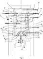
Figure 1 is a schematic view of a gasification plant according to the invention; -
Figure 2 is a perspective view of the reactor of a gasification plant according to the invention, in which the biomass pyrolysis, the combustion of the pyrolysis products and the reduction of gases produced during combustion are carried out, in order to obtain the synthesis gas; -
Figure 3 is an elevation view of the reactor illustrated inFigure 2 ; -
Figure 4 is a section ofFigure 3 , along the line A-A inFigure 3 ; -
Figure 5 is a section ofFigure 3 , along the line B-B inFigure 3 ; -
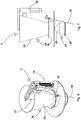
Figure 6 is a perspective view of a detail of the gasification plant according to the invention; -
Figure 7 in an elevation view of the detail ofFigure 6 in a first operative position, -
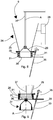
Figure 8 is a section view of the detail ofFigures 6 and 7 , in a second operative position; -
Figure 9 is a section view of a detail ofFigure 7 . - Referring to
Figure 1 , a gasification plant according to the invention comprises areactor 2 in which the pyrolysis of the biomass to be gasified, the combustion of pyrolysis products and the reduction of the combustion products occur, for producing a combustible gas, commonly denominated as synthesis gas, or syngas. - The
reactor 2 comprises ashell 10, within which areactor body 11 is housed (Figure 4 ), into which the biomass to be treated is delivered and inside which the chemical-physical processes conducting to the synthesis production occur. - The gasification plant 1 further comprises a
supply tank 3, which contains the biomass with which thereactor 2 is supplied and afilter 4 in which filtering of synthesis gas produced occurs. - The biomass contained in the
supply tank 3 is transported to thereactor 2 by means of afirst conveying device 5, for example a first cochlea conveying device, which introduces the biomass into thereactor body 11 by means of ahopper 6, connected to a supply opening 7 ofreactor 2, placed in an upper zone of thereactor body 11. - The combustion solid residues and the synthesis gas produced in
reactor 3 are transported fromreactor 2 to thefilter 4 by means of asecond conveying device 8, for example a second cochlea conveying device actuated by amotor 20, or by pneumatic transport. - The
reactor body 11 substantially comprises four zones: afirst pyrolysis zone 12, placed in the upper part of thereactor body 11, into which biomass to be treated is delivered and in which biomass undergoes a pyrolysis treatment. In thisfirst zone 12, alevel sensor 23 is provided, which can consist of, for example, a touching device, to verify whether the level of the biomass introduced in saidfirst zone 12 reaches and exceeds a pre-established maximum value and thus to reduce the biomass supply. - A
second combustion zone 13, placed in an intermediate part of thereactor body 11, in which combustion of products of the pyrolysis treatment is carried out. - A
third reduction zone 14, placed in a lower part of thereactor body 11, where a reduction reaction of the gases produced by the combustion and the so called "cracking" of tars produced during the biomass combustion, that is the conversion of heavy hydrocarbons into light hydrocarbons, occur. - A
fourth unloading zone 15 where solid products of the combustion of biomass, consisting substantially in powder and carbon granules, and the synthesis gas produced are unloaded fromreactor 2. - The
second combustion zone 13 can end up with atruncated cone element 16, that narrows downwards to anoutlet port 48 having a first diameter D, and facilitating the transit of the combustion solid residual material from thesecond zone 13 to thethird zone 14. - In the
second zone 13 an air flow is delivered for implementing the combustion of material coming from the biomass which has already undergone the pyrolysis treatment in thefirst zone 12 of thereactor body 11. The amount of air delivery is lower than the stoichiometric amount required for a complete combustion of products of the pyrolysis treatment, such as to carry out an incomplete combustion under oxygen shortage conditions. The amount of air delivered can be equal, for example, to 40% of the stoichiometric amount required for a complete combustion. - In the
second zone 13 at least oneignition device 49 is arranged, for example consisting in an electric cartridge resistance, useful for triggering combustion of the biomass when thereactor 2 is started. In the illustrated embodiment, twoignition devices 49 are provided. However, any number ofignition devices 49 can be provided, without departing from the scope of the present invention. - Air is delivered into the
second zone 13 through a plurality ofair injectors 22, which lead to saidsecond zone 13 and which are supplied by means of a fan (not visible in the drawings).Injectors 22 are distributed at a substantially constant angular pitch along the periphery of thesecond zone 13 and are tilted in relation to a direction perpendicular to theouter surface 51 of thesecond zone 13, with a tilt angle comprised, for example, between 10° and 20°, so that to create a vortex motion of the air in saidzone 13 to promote an improved mixing of air with the material to be submitted to combustion, in order to obtain a greater combustion uniformity. - The
third reduction zone 14 has a first truncatedcone portion 17, enlarging downwards until a second diameter D1, followed by acylindrical portion 18 with diameter D1. - The Applicant has experimentally determined that suitably selecting the ratio between diameters D and D1 and between volume V of the
second combustion zone 13 and volume VI of thethird reduction zone 14 it is possible to greatly reduce the percentage of tars in the gas produced, for example until few tens of part per million, which allows to obtain a gas which can be directly used without further treatment for supplying, for example, an internal combustion motor. - The Applicant has determined that the above indicated result can be advantageously obtained with a ratio D1/D ≥ 2.5 and with a ratio V1/V ≥ 3.5.
- In order to avoid an undesired delivery of air from the outside which might compromise the pyrolysis process in the
first zone 12 of thereactor body 11, alter the combustion process of thesecond zone 13 of thereactor body 11 and the reduction process in thethird zone 14 of thereactor body 11, thereactor body 11 is made of a very low porosity refractory material, which dramatically limits air infiltrations, and therefore, oxygen from the outside and emission of vapours, gases and fumes from thereactor body 11. - By very low porosity refractory material it is meant a refractory material which has a closed porosity percentage not lower than 85% and pores with average diameter not higher than 60 microns.
- Such a type of material can be, for example, the silicon carbide-based material sold with the trade name "Iker" from Italker S.r.l. company, which comprises among its constituents 60-80% of silicon carbide, 10-30% of silica and 10-20% of alumina.
- The
reactor body 11 is externally coated, at thefirst zone 12,second zone 13 andthird zone 14 with a thermally insulating material in order to minimize heat dispersion from thereactor body 11 towards the outside, thereby improving the performances of the gasification apparatus according to the invention. The external surface of thefourth unloading zone 15 of thereactor body 11 is not coated on the contrary with said thermally insulating material. - Around the
fourth unloading zone 15 of the reactor body 11 aheat exchange device 32 is arranged, in which theair supplying injectors 22 is preheated. Theheat exchange device 32 is provided with adelivery conduit 33, through which air to be preheated can be delivered into the furtherheat exchange device 32. - The
heat exchange device 32 is connected toinjectors 22 by means of respective connectingconduits 34. - In order to pre-heat air heat coming from the
fourth unloading zone 15 of thereactor body 11 is used, which is transmitted to theheat exchange device 32 as the external surface of saidfourth unloading zone 15, as previously specified, is not provided with an insulating material external coating. - Air can be delivered into the
heat exchange device 32 by means of a fan device (not illustrated), or creating a depression inside thereactor body 11, suctioning air through thedischarge conduit 19. The depression created within thereactor body 11 is transmitted to theheat exchange device 32 through connectingconduits 34, thus determining air suction from the outside via thedelivery conduit 33. - In the
fourth unloading zone 15 anunloading device 38 is arranged of solid residue materials of the combustion of biomass and synthesis gas produced inreactor 2. - The
unloading device 38 is composed of an internallyhollow body 39, the inside of which communicates with thedischarge conduit 19. Thebody 39 has a truncated cone or truncated pyramid shape on a side surface of whichslits 40 are made through which solid residues and synthesis gas are sent into thedischarge conduit 19. - The
body 39 can be advantageously made of the same material as thereactor body 11 is made, or of a metal material. - If the
body 39 has a truncated cone shape,slits 40 are made along generating lines of the truncated cone and are distributed with a constant angular pitch. If, otherwise, thebody 39 has a truncated pyramid shape,slits 40 are made along corners ofbody 39. - The
body 39 is fixed to ashaft 41 that can be driven to rotate, by means of amotor 42, about a longitudinal axis B of thereactor body 11. Theshaft 41 is mounted in asupport 43 with an airtight coupling, to avoid an undesired delivery, not controllable, of air in thereactor body 11. - The peculiar structure of the
unloading device 38 resulted to be particularly suitable for carrying out the unloading of the solid products of the biomass combustion with no risk of obstructions that may block the unloading of said solid products. - The combustion solid residues and the synthesis gas produced in
reactor 3 are unloaded from thefourth zone 15 ofreactor 2, by means of theunloading device 38, into adischarge conduit 19 communicating with the second conveyingdevice 8, by means of which the combustion solid residues and the synthesis gas are conveyed from thereactor 2 to thefilter 4. - Discharging into the
discharge conduit 19 the synthesis gas produced inreactor 3 together with the combustion solid residues has the advantage that solid residues, while being conveyed by theconveyor 8 to thefilter 4 stay in contact with the synthesis gas and depurate it from possible tar residues present therein, before being separated from the synthesis gas infilter 4. This precaution allows to minimize tar content in the synthesis gas, thus obtaining a synthesis gas with a remarkably high purity degree. - The
second conveyor device 8 is inserted inside a furtherheat exchange device 21 through which the synthesis gas exiting fromreactor 2 is cooled by an air flow generated in the furtherheat exchange device 21 by means of a fan (not visible in the drawings). This fan can also be used to generate a depression in thedischarge conduit 19 of thereactor body 11, in order to deliver air into theheat exchange device 32. - Hot air exiting from the
heat exchange device 21 can be used for different purposes, for example to reduce the percentage of biomass humidity, before it is reinserted intoreactor 2. - The
supply tank 3 is provided with asupply valve 9, which will be described below in more detail. Thesupply valve 9 is mounted in an airtight manner in a delivery opening of the supply tank 3 (not visible in the drawings). Thesupply tank 3 is made so that, when thesupply valve 9 is in the closed position air cannot enter in an uncontrolled way inside the tank and, therefrom into thereactor body 11. - For the same reason, the first conveying
device 5 is made airtight and it is airtightly coupled with thesupply tank 3 and with thehopper 6. The latter is connected airtightly to thesupply opening 7 of thereactor body 11. - Air-tightness is required to avoid significant amounts of air to penetrate in an uncontrolled manner from the outside inside the
first zone 12 of thereactor body 11 causing a biomass combustion in saidfirst zone 12 with the risk of bursts and flash-backs and fumes in the first conveyingdevice 5 and in thesupply tank 3. - It is true that, when the
supply valve 9 opens to allow the delivery of biomass into thesupply tank 3, a certain amount of air enters thesupply tank 3 together with the biomass and can reach thefirst zone 12 of thereactor body 11, however they are small amounts of air, not sufficient to trigger a combustion of the biomass in saidfirst zone 12. - The second conveying
device 8 also is made airtight and is airtightly connected with thedischarge conduit 19, to avoid an uncontrolled inlet of air that might trigger a combustion of the synthesis gas produced. - The
supply valve 9 comprises avalve body 24 comprising a first truncated cone shapedportion 25 with the major base addressed upwards, serving as a hopper into which the biomass to be charged into thetank 3 is delivered by means of a conveying device, not visible in the drawings. Thebody 24 further comprises a second externallycylinder portion 26, which is connected airtightly with a supply opening (not visible in the drawings) of thesupply tank 3 and it is provided with an inner pass-throughhole 36 having truncated cone shape with the minor base addressed upwards. - The
valve 9 further comprises ashutter device 27 which is actuated to move along a longitudinal axis A of thevalve body 24 by means of alinear actuator 28. - The
shutter device 27 comprises afirst portion 29, connected with amanoeuvring arm 37, in turn connected with thelinear actuator 28 which moves themanoeuvring arm 37 and, consequently theshutter device 27 along said longitudinal axis A. - The
shutter device 27 further comprises asecond portion 30 having such shape and dimensions as to be able to couple by shape-coupling with the surface of saidinner hole 36, to take thesupply valve 9 into the closed position. - The surface of the
inner hole 36 is provided by at least aseal gasket 31, preferably a plurality of seal gaskets, to guarantee that the geometric coupling between theshutter 27 and theinner hole 36 is airtight. - The
valve 9 is associated to alevel sensor 35 which is used to detect the level of the biomass inside thetank 3, to adjust the biomass supply to thetank 3. - The
reactor 2 is provided with asafety device 44 configured for absorbing and venting possible overpressures which might occur within thereactor 2. - The
safety device 44 can be composed of a so-called hydraulic guard, comprising atank 45, within which an inert liquid is contained, i.e. a liquid which cannot react with gas substances coming from the inside of the reactor, for example water. Thetank 45 is connected with thereactor 2 via atube 46 which, for example, can be connected with thehopper 6 through which the biomass is introduced in thereactor 2. - The
tank 45 is provided with alid 48 which is connected with thetank 45 so that it can move in a direction parallel to aside wall 47 of thetank 45, so that between thetank 45 and the lid 48 a port is created through which a possible overpressure occurring within thereactor 2 is vented. Thetank 45 can be provided with a level sensor configured to indicate whether the level of the liquid in thetank 45 lowers below a predefined minimum level and whether some liquid must be delivered in thetank 45, to return the level of the liquid above said minimum level. - Instead of the hydraulic guard a rupture disk (not illustrated) can be provided, placed on a flange of the
shell 10 of thereactor 2, which thehopper 6 is fixed to. - The
reactor 2 is further provided with a plurality oftemperature sensors 50, distributed over the first 12, second 13, third 14 and fourth 15 zone of thereactor body 11, through which it is possible to monitor the temperature in the aforesaid zones and to verify the correct functioning of thereactor 2. - Hereinafter the functioning of the gasification plant 1 according to the invention is disclosed.
- Before starting the
reactor 2 it is necessary to fill with carbon powder the second conveyingdevice 8 and thereactor body 11 up until a level near to theoutlet port 48 of thetruncated cone element 16. The remaining volume of thereactor body 11, i.e. thepyrolysis zone 12 and thecombustion zone 13 can be filled with the biomass to be treated. - Once the filling of the
reactor body 11 is terminated, the at least oneignition device 49 is activated to start the combustion of the biomass in thesecond combustion zone 13 of thereactor body 11 and air is delivered into thesecond combustion zone 13 throughinjectors 22, in an amount lower than the stochiometric amount required for a complete combustion of the biomass, for example equal to about 40% of said stoichiometric quantity. - Heat produced by the biomass combustion in the
second combustion zone 13 starts and supplies the pyrolysis treatment of the biomass in thefirst pyrolysis zone 12. - In full operation, the biomass introduced into the
reactor 2 undergoes a first treatment of pyrolysis in thefirst pyrolysis zone 12, then it passes into thesecond combustion zone 13 in which it is subjected to incomplete combustion under oxygen-shortage conditions. Biomass combustion products, substantially consisting in carbon powder, synthesis gas and tars pass into thethird reduction zone 14 where a reduction reaction of gases produced by combustion and the so called "cracking" of tars produced during biomass combustion, that is the conversion of heavy hydrocarbons into light hydrocarbons, occur. - Finally, biomass combustion products arrive in the
fourth unloading zone 15, wherefrom they are discharged through thedischarge conduit 19 through theunloading device 38. - Through the
discharge conduit 19 the combustion products arrive to the second conveyingdevice 8 which conveys them to thefilter 4, in which the synthesis gas and the carbon powder are separated and sent to their respective stock tanks. Alternatively, the synthesis gas can be directly sent to the supply of an internal combustion motor. - Cooling of the conveying
device 8 through theheat exchanger 21 allows to obtain condensation of possible tars contained in the synthesis gas, so that they are absorbed by the carbon powder, so as to obtain a synthesis gas substantially free from tars.
Claims (15)
- Gasification plant (1) for producing combustible gas, or synthesis gases, by pyrolysis and combustion of biomass comprising a reactor (2) supplied with said biomass, said reactor (2) comprises a reactor body (11) that is supplied with said biomass through a supply opening (7), said reactor body (7) comprising a first pyrolysis zone (12) in which said biomass is subjected to pyrolysis treatment, a second combustion zone (13), in which the products of said pyrolysis treatment are subjected to combustion in oxygen shortage conditions, a third reduction zone (14) in which the combustion products are subjected to reduction so as to obtain said synthesis gas and a fourth unloading zone (15) from which solid combustion residues and synthesis gases are discharged from the reactor (2), characterized in that said fourth unloading zone (15) comprises an unloading device (38) for solid residual materials of the combustion of biomass and synthesis gas produced in the reactor (2), said unloading device (38) comprising an internally hollow body (39), the inside of which communicates with a discharge conduit (19) in which said synthesis gas and said residues of the combustion are discharged together, said body (39) being able to rotate around a longitudinal axis (B) of the reactor (2), said body (39) having a truncated cone shape or truncated pyramid shape on a side surface of which slits (40) are made.
- Gasification plant according to claim 1, wherein, if said body (39) has a truncated cone shape, said slits (40) are arranged along generators of said side surface, distributed at a constant angular pitch, whereas if said body (39) has a truncated pyramid shape, said slits are arranged along corners of said side surface.
- Gasification plant (1) according to claim 1, or 2, wherein said body (39) is fixed to a shaft (41) drivable to rotate, by a motor (42), around a longitudinal axis (B) of the reactor body (11), said shaft (41) being mounted in a support (43), with an airtight coupling.
- Gasification plant (1) according to any of claims 1 to 3, wherein said reactor body (11) is made of a refractory material with very low porosity having a closed porosity percentage of not less than 85% and pores with an average diameter not higher than 60 microns.
- Gasification plant (1) according to claim 4, wherein said very low porosity material is a material comprising silicon carbide, silica and alumina.
- Gasification plant (1) according to any of claims 1 to 5, further comprising a supply tank (3) into which said biomass intended for supplying said reactor (2) is delivered, said supply tank being connected to a first conveying device (5) that removes said biomass from said supply tank (3) and conveys the biomass to said supply opening (7) by delivering said biomass to said supply opening (7) via a hopper (6) fixed to said supply opening (7), said first conveying device (5) being made airtight and being coupled in an airtight manner with the supply tank (3) and with the hopper (6), said hopper (6) being connected in an airtight manner to the supply opening (7) of the reactor body (11).
- Gasification plant (1) according to any of claims 1 to 6, wherein said supply tank (3) is provided with a supply valve (9) mounted in an airtight manner in a delivery opening of the supply tank (3), said supply tank (3) being made in such a manner that, when the supply valve (9) is in closed position air cannot enter inside the supply tank (3).
- Gasification plant (1) according to any of claims 1 to 7, further comprising a safety device (44) configured for venting overpressures that occur inside the reactor body (2), said safety device (44) comprising a tank (45), inside which an inert liquid is contained, said tank (45) being connected to the reactor body (11) by a pipe (46), said tank (45) being provided with a lid (46) that is connected to the tank (45) so as to be able to move in a direction parallel to a side wall (47) of the tank (45).
- Gasification plant (1) according to any of claims 1 to 8, wherein said reactor body (11) is coated with a thermally insulating material at least at said first pyrolysis zone (12), at said second combustion zone (13) and at said third reduction zone (14).
- Gasification plant (1) according to claim 9, wherein said reactor body is devoid of thermally insulating coating at said fourth unloading zone (15).
- Gasification plant (1) according to claim 9, or 10, wherein around the fourth unloading zone (15) of the reactor body (11) a heat exchange device (32) is arranged, in which air is preheated that is intended to be delivered to said second combustion zone (13), by a plurality of air injectors (22) connected to said heat exchanger (32) via respective connecting conduits (34), said air being delivered to said heat exchanger (32) by a delivery conduit (33).
- Gasification plant (1) according to claim 11, wherein said air injectors (22) are distributed at a substantially constant angular pitch along a periphery of the second combustion zone (13) and are tilted in relation to a direction that is perpendicular to an outer surface (51) of the second combustion zone (13) with a tilt angle comprised between 10° and 20°.
- Gasification plant (1) according to any of claims 1 to 12, wherein said discharge conduit (19) is connected to a second conveying device (8), said second conveying device (8) being inserted inside a further heat exchange device (21).
- Gasification plant according to claim 13, wherein said second conveying device (8) is made airtight.
- Gasification plant (1) according to any of claims 1 to 14, further comprising at least one ignition device (49) configured for triggering combustion of said biomass in said second combustion zone (13).
Applications Claiming Priority (4)
| Application Number | Priority Date | Filing Date | Title |
|---|---|---|---|
| IT201800002481A IT201800002481A1 (en) | 2018-02-08 | 2018-02-08 | Gasifier plant |
| IT201800002482A IT201800002482A1 (en) | 2018-02-08 | 2018-02-08 | Gasifier plant |
| IT201800002483A IT201800002483A1 (en) | 2018-02-08 | 2018-02-08 | Gasifier plant |
| PCT/IB2019/050943 WO2019155373A1 (en) | 2018-02-08 | 2019-02-06 | Gasification plant |
Publications (2)
| Publication Number | Publication Date |
|---|---|
| EP3749734A1 EP3749734A1 (en) | 2020-12-16 |
| EP3749734B1 true EP3749734B1 (en) | 2021-12-22 |
Family
ID=65628803
Family Applications (1)
| Application Number | Title | Priority Date | Filing Date |
|---|---|---|---|
| EP19708358.7A Active EP3749734B1 (en) | 2018-02-08 | 2019-02-06 | Gasification plant |
Country Status (6)
| Country | Link |
|---|---|
| EP (1) | EP3749734B1 (en) |
| JP (1) | JP7386813B2 (en) |
| CA (1) | CA3090756A1 (en) |
| ES (1) | ES2908469T3 (en) |
| WO (1) | WO2019155373A1 (en) |
| ZA (1) | ZA202005527B (en) |
Families Citing this family (1)
| Publication number | Priority date | Publication date | Assignee | Title |
|---|---|---|---|---|
| IT202400001554A1 (en) * | 2024-01-26 | 2025-07-26 | Spa Curti Costruzioni Meccaniche | INJECTOR FOR A GASIFICATION SYSTEM |
Family Cites Families (10)
| Publication number | Priority date | Publication date | Assignee | Title |
|---|---|---|---|---|
| DE19608826C2 (en) * | 1996-03-07 | 1998-03-26 | Walter Kuntschar | DC gasification reactor |
| CA2430999C (en) * | 2000-12-08 | 2012-01-10 | Foretop Corporation | Process and gas generator for generating fuel gas |
| DK174582B1 (en) * | 2001-11-05 | 2003-06-30 | Biosynergi Proces Aps | Solid biofuel gasification process and generator |
| US9587186B2 (en) * | 2008-09-04 | 2017-03-07 | Epic Clean Technologies Corporation | Pressurized gasification apparatus to convert coal or other carbonaceous material to gas while producing a minimum amount of tar |
| US8450552B2 (en) * | 2009-05-18 | 2013-05-28 | Exxonmobil Chemical Patents Inc. | Pyrolysis reactor materials and methods |
| US8932534B2 (en) * | 2009-11-20 | 2015-01-13 | Exxonmobil Chemical Patents Inc. | Porous pyrolysis reactor materials and methods |
| US8721748B1 (en) * | 2013-01-28 | 2014-05-13 | PHG Energy, LLC | Device with dilated oxidation zone for gasifying feedstock |
| SG11201505847QA (en) * | 2013-01-28 | 2015-08-28 | Phg Energy Llc | Method and device for gasifying feedstock |
| US10011793B2 (en) * | 2013-07-19 | 2018-07-03 | V-GRID Energy Systems | Coaxial gasifier for enhanced hydrogen production |
| JP6280484B2 (en) * | 2014-10-05 | 2018-02-14 | 株式会社 森のエネルギー研究所 | Woody biomass gasifier |
-
2019
- 2019-02-06 EP EP19708358.7A patent/EP3749734B1/en active Active
- 2019-02-06 ES ES19708358T patent/ES2908469T3/en active Active
- 2019-02-06 WO PCT/IB2019/050943 patent/WO2019155373A1/en not_active Ceased
- 2019-02-06 CA CA3090756A patent/CA3090756A1/en active Pending
- 2019-02-06 JP JP2020565029A patent/JP7386813B2/en active Active
-
2020
- 2020-09-07 ZA ZA2020/05527A patent/ZA202005527B/en unknown
Also Published As
| Publication number | Publication date |
|---|---|
| ZA202005527B (en) | 2022-10-26 |
| JP7386813B2 (en) | 2023-11-27 |
| CA3090756A1 (en) | 2019-08-15 |
| JP2021513599A (en) | 2021-05-27 |
| WO2019155373A1 (en) | 2019-08-15 |
| EP3749734A1 (en) | 2020-12-16 |
| ES2908469T3 (en) | 2022-04-29 |
Similar Documents
| Publication | Publication Date | Title |
|---|---|---|
| US4530702A (en) | Method for producing fuel gas from organic material, capable of self-sustaining operation | |
| KR101299433B1 (en) | A process and an apparatus for converting solid organic materials into carbon or activated carbon | |
| CA2714206C (en) | Method and apparatus for receiving fine-grained to coarse-grained solids from a vessel and transferring them to a higher-pressure system | |
| US10752841B2 (en) | Pyrolysis reactor | |
| CN110662820B (en) | microwave pyrolysis reactor | |
| US9279090B2 (en) | Method for cleaning producer gas using a microwave induced plasma cleaning device | |
| EP0403381B1 (en) | Process and apparatus for regulating or controlling the heat level of a pulverulent solid material comprising a fluidised or moving bed partitioned heat-exchanger | |
| CN112639056B (en) | Microwave pyrolysis reactor | |
| CN102575846A (en) | Closed vessel arrangement for safe destruction of rocket motors | |
| WO2019155373A1 (en) | Gasification plant | |
| JP7789322B2 (en) | Gasifier | |
| JP5990417B2 (en) | Volume reduction equipment for radioactive waste | |
| CN112646604B (en) | Sleeve type double-oxide-layer fixed bed gasifier and organic solid waste gasification method | |
| WO2008004357A1 (en) | Equipment for converting plastics into oil | |
| JP6559080B2 (en) | Radioactive waste volume reduction treatment apparatus and volume reduction treatment method | |
| CN120641207A (en) | Apparatus and method for efficient production of hydrogen by pyrolysis | |
| CN111282519B (en) | A fixed bed reactor | |
| KR20230146520A (en) | carbide collector | |
| IT201800002482A1 (en) | Gasifier plant | |
| IT201800002483A1 (en) | Gasifier plant | |
| CN212246891U (en) | Vertical garbage disposal furnace and garbage disposal system | |
| JP2024042723A (en) | Biomass Gasifier | |
| CN220724038U (en) | Microwave pyrolysis solid waste treatment device for producing combustible gas | |
| JP2007302449A (en) | Powder storage device | |
| JP4450814B2 (en) | Coated fuel particle manufacturing equipment for HTGR |
Legal Events
| Date | Code | Title | Description |
|---|---|---|---|
| STAA | Information on the status of an ep patent application or granted ep patent |
Free format text: STATUS: UNKNOWN |
|
| STAA | Information on the status of an ep patent application or granted ep patent |
Free format text: STATUS: THE INTERNATIONAL PUBLICATION HAS BEEN MADE |
|
| PUAI | Public reference made under article 153(3) epc to a published international application that has entered the european phase |
Free format text: ORIGINAL CODE: 0009012 |
|
| STAA | Information on the status of an ep patent application or granted ep patent |
Free format text: STATUS: REQUEST FOR EXAMINATION WAS MADE |
|
| 17P | Request for examination filed |
Effective date: 20200903 |
|
| AK | Designated contracting states |
Kind code of ref document: A1 Designated state(s): AL AT BE BG CH CY CZ DE DK EE ES FI FR GB GR HR HU IE IS IT LI LT LU LV MC MK MT NL NO PL PT RO RS SE SI SK SM TR |
|
| AX | Request for extension of the european patent |
Extension state: BA ME |
|
| RAV | Requested validation state of the european patent: fee paid |
Extension state: MD Effective date: 20200903 Extension state: TN Effective date: 20200903 |
|
| GRAP | Despatch of communication of intention to grant a patent |
Free format text: ORIGINAL CODE: EPIDOSNIGR1 |
|
| STAA | Information on the status of an ep patent application or granted ep patent |
Free format text: STATUS: GRANT OF PATENT IS INTENDED |
|
| INTG | Intention to grant announced |
Effective date: 20210712 |
|
| GRAS | Grant fee paid |
Free format text: ORIGINAL CODE: EPIDOSNIGR3 |
|
| GRAA | (expected) grant |
Free format text: ORIGINAL CODE: 0009210 |
|
| STAA | Information on the status of an ep patent application or granted ep patent |
Free format text: STATUS: THE PATENT HAS BEEN GRANTED |
|
| AK | Designated contracting states |
Kind code of ref document: B1 Designated state(s): AL AT BE BG CH CY CZ DE DK EE ES FI FR GB GR HR HU IE IS IT LI LT LU LV MC MK MT NL NO PL PT RO RS SE SI SK SM TR |
|
| REG | Reference to a national code |
Ref country code: GB Ref legal event code: FG4D |
|
| REG | Reference to a national code |
Ref country code: CH Ref legal event code: EP |
|
| REG | Reference to a national code |
Ref country code: DE Ref legal event code: R096 Ref document number: 602019010283 Country of ref document: DE |
|
| REG | Reference to a national code |
Ref country code: AT Ref legal event code: REF Ref document number: 1457078 Country of ref document: AT Kind code of ref document: T Effective date: 20220115 |
|
| REG | Reference to a national code |
Ref country code: IE Ref legal event code: FG4D |
|
| REG | Reference to a national code |
Ref country code: LT Ref legal event code: MG9D |
|
| PG25 | Lapsed in a contracting state [announced via postgrant information from national office to epo] |
Ref country code: RS Free format text: LAPSE BECAUSE OF FAILURE TO SUBMIT A TRANSLATION OF THE DESCRIPTION OR TO PAY THE FEE WITHIN THE PRESCRIBED TIME-LIMIT Effective date: 20211222 Ref country code: LT Free format text: LAPSE BECAUSE OF FAILURE TO SUBMIT A TRANSLATION OF THE DESCRIPTION OR TO PAY THE FEE WITHIN THE PRESCRIBED TIME-LIMIT Effective date: 20211222 Ref country code: FI Free format text: LAPSE BECAUSE OF FAILURE TO SUBMIT A TRANSLATION OF THE DESCRIPTION OR TO PAY THE FEE WITHIN THE PRESCRIBED TIME-LIMIT Effective date: 20211222 Ref country code: BG Free format text: LAPSE BECAUSE OF FAILURE TO SUBMIT A TRANSLATION OF THE DESCRIPTION OR TO PAY THE FEE WITHIN THE PRESCRIBED TIME-LIMIT Effective date: 20220322 |
|
| REG | Reference to a national code |
Ref country code: NL Ref legal event code: MP Effective date: 20211222 Ref country code: ES Ref legal event code: FG2A Ref document number: 2908469 Country of ref document: ES Kind code of ref document: T3 Effective date: 20220429 |
|
| PG25 | Lapsed in a contracting state [announced via postgrant information from national office to epo] |
Ref country code: SE Free format text: LAPSE BECAUSE OF FAILURE TO SUBMIT A TRANSLATION OF THE DESCRIPTION OR TO PAY THE FEE WITHIN THE PRESCRIBED TIME-LIMIT Effective date: 20211222 Ref country code: NO Free format text: LAPSE BECAUSE OF FAILURE TO SUBMIT A TRANSLATION OF THE DESCRIPTION OR TO PAY THE FEE WITHIN THE PRESCRIBED TIME-LIMIT Effective date: 20220322 Ref country code: LV Free format text: LAPSE BECAUSE OF FAILURE TO SUBMIT A TRANSLATION OF THE DESCRIPTION OR TO PAY THE FEE WITHIN THE PRESCRIBED TIME-LIMIT Effective date: 20211222 Ref country code: HR Free format text: LAPSE BECAUSE OF FAILURE TO SUBMIT A TRANSLATION OF THE DESCRIPTION OR TO PAY THE FEE WITHIN THE PRESCRIBED TIME-LIMIT Effective date: 20211222 Ref country code: GR Free format text: LAPSE BECAUSE OF FAILURE TO SUBMIT A TRANSLATION OF THE DESCRIPTION OR TO PAY THE FEE WITHIN THE PRESCRIBED TIME-LIMIT Effective date: 20220323 |
|
| PG25 | Lapsed in a contracting state [announced via postgrant information from national office to epo] |
Ref country code: NL Free format text: LAPSE BECAUSE OF FAILURE TO SUBMIT A TRANSLATION OF THE DESCRIPTION OR TO PAY THE FEE WITHIN THE PRESCRIBED TIME-LIMIT Effective date: 20211222 |
|
| PG25 | Lapsed in a contracting state [announced via postgrant information from national office to epo] |
Ref country code: SM Free format text: LAPSE BECAUSE OF FAILURE TO SUBMIT A TRANSLATION OF THE DESCRIPTION OR TO PAY THE FEE WITHIN THE PRESCRIBED TIME-LIMIT Effective date: 20211222 Ref country code: SK Free format text: LAPSE BECAUSE OF FAILURE TO SUBMIT A TRANSLATION OF THE DESCRIPTION OR TO PAY THE FEE WITHIN THE PRESCRIBED TIME-LIMIT Effective date: 20211222 Ref country code: RO Free format text: LAPSE BECAUSE OF FAILURE TO SUBMIT A TRANSLATION OF THE DESCRIPTION OR TO PAY THE FEE WITHIN THE PRESCRIBED TIME-LIMIT Effective date: 20211222 Ref country code: PT Free format text: LAPSE BECAUSE OF FAILURE TO SUBMIT A TRANSLATION OF THE DESCRIPTION OR TO PAY THE FEE WITHIN THE PRESCRIBED TIME-LIMIT Effective date: 20220422 Ref country code: EE Free format text: LAPSE BECAUSE OF FAILURE TO SUBMIT A TRANSLATION OF THE DESCRIPTION OR TO PAY THE FEE WITHIN THE PRESCRIBED TIME-LIMIT Effective date: 20211222 Ref country code: CZ Free format text: LAPSE BECAUSE OF FAILURE TO SUBMIT A TRANSLATION OF THE DESCRIPTION OR TO PAY THE FEE WITHIN THE PRESCRIBED TIME-LIMIT Effective date: 20211222 |
|
| VS25 | Lapsed in a validation state [announced via postgrant information from nat. office to epo] |
Ref country code: MD Free format text: LAPSE BECAUSE OF FAILURE TO SUBMIT A TRANSLATION OF THE DESCRIPTION OR TO PAY THE FEE WITHIN THE PRESCRIBED TIME-LIMIT Effective date: 20211222 |
|
| PG25 | Lapsed in a contracting state [announced via postgrant information from national office to epo] |
Ref country code: PL Free format text: LAPSE BECAUSE OF FAILURE TO SUBMIT A TRANSLATION OF THE DESCRIPTION OR TO PAY THE FEE WITHIN THE PRESCRIBED TIME-LIMIT Effective date: 20211222 |
|
| REG | Reference to a national code |
Ref country code: DE Ref legal event code: R097 Ref document number: 602019010283 Country of ref document: DE |
|
| PG25 | Lapsed in a contracting state [announced via postgrant information from national office to epo] |
Ref country code: MC Free format text: LAPSE BECAUSE OF FAILURE TO SUBMIT A TRANSLATION OF THE DESCRIPTION OR TO PAY THE FEE WITHIN THE PRESCRIBED TIME-LIMIT Effective date: 20211222 Ref country code: IS Free format text: LAPSE BECAUSE OF FAILURE TO SUBMIT A TRANSLATION OF THE DESCRIPTION OR TO PAY THE FEE WITHIN THE PRESCRIBED TIME-LIMIT Effective date: 20220422 |
|
| REG | Reference to a national code |
Ref country code: BE Ref legal event code: MM Effective date: 20220228 |
|
| PLBE | No opposition filed within time limit |
Free format text: ORIGINAL CODE: 0009261 |
|
| STAA | Information on the status of an ep patent application or granted ep patent |
Free format text: STATUS: NO OPPOSITION FILED WITHIN TIME LIMIT |
|
| PG25 | Lapsed in a contracting state [announced via postgrant information from national office to epo] |
Ref country code: LU Free format text: LAPSE BECAUSE OF NON-PAYMENT OF DUE FEES Effective date: 20220206 Ref country code: DK Free format text: LAPSE BECAUSE OF FAILURE TO SUBMIT A TRANSLATION OF THE DESCRIPTION OR TO PAY THE FEE WITHIN THE PRESCRIBED TIME-LIMIT Effective date: 20211222 Ref country code: AL Free format text: LAPSE BECAUSE OF FAILURE TO SUBMIT A TRANSLATION OF THE DESCRIPTION OR TO PAY THE FEE WITHIN THE PRESCRIBED TIME-LIMIT Effective date: 20211222 |
|
| 26N | No opposition filed |
Effective date: 20220923 |
|
| PG25 | Lapsed in a contracting state [announced via postgrant information from national office to epo] |
Ref country code: IE Free format text: LAPSE BECAUSE OF NON-PAYMENT OF DUE FEES Effective date: 20220206 |
|
| PG25 | Lapsed in a contracting state [announced via postgrant information from national office to epo] |
Ref country code: SI Free format text: LAPSE BECAUSE OF FAILURE TO SUBMIT A TRANSLATION OF THE DESCRIPTION OR TO PAY THE FEE WITHIN THE PRESCRIBED TIME-LIMIT Effective date: 20211222 Ref country code: BE Free format text: LAPSE BECAUSE OF NON-PAYMENT OF DUE FEES Effective date: 20220228 |
|
| REG | Reference to a national code |
Ref country code: AT Ref legal event code: UEP Ref document number: 1457078 Country of ref document: AT Kind code of ref document: T Effective date: 20211222 |
|
| PG25 | Lapsed in a contracting state [announced via postgrant information from national office to epo] |
Ref country code: MK Free format text: LAPSE BECAUSE OF FAILURE TO SUBMIT A TRANSLATION OF THE DESCRIPTION OR TO PAY THE FEE WITHIN THE PRESCRIBED TIME-LIMIT Effective date: 20211222 Ref country code: CY Free format text: LAPSE BECAUSE OF FAILURE TO SUBMIT A TRANSLATION OF THE DESCRIPTION OR TO PAY THE FEE WITHIN THE PRESCRIBED TIME-LIMIT Effective date: 20211222 |
|
| PG25 | Lapsed in a contracting state [announced via postgrant information from national office to epo] |
Ref country code: HU Free format text: LAPSE BECAUSE OF FAILURE TO SUBMIT A TRANSLATION OF THE DESCRIPTION OR TO PAY THE FEE WITHIN THE PRESCRIBED TIME-LIMIT; INVALID AB INITIO Effective date: 20190206 |
|
| PG25 | Lapsed in a contracting state [announced via postgrant information from national office to epo] |
Ref country code: MT Free format text: LAPSE BECAUSE OF FAILURE TO SUBMIT A TRANSLATION OF THE DESCRIPTION OR TO PAY THE FEE WITHIN THE PRESCRIBED TIME-LIMIT Effective date: 20211222 |
|
| PG25 | Lapsed in a contracting state [announced via postgrant information from national office to epo] |
Ref country code: TR Free format text: LAPSE BECAUSE OF FAILURE TO SUBMIT A TRANSLATION OF THE DESCRIPTION OR TO PAY THE FEE WITHIN THE PRESCRIBED TIME-LIMIT Effective date: 20211222 |
|
| REG | Reference to a national code |
Ref country code: CH Ref legal event code: U11 Free format text: ST27 STATUS EVENT CODE: U-0-0-U10-U11 (AS PROVIDED BY THE NATIONAL OFFICE) Effective date: 20260301 |
|
| PGFP | Annual fee paid to national office [announced via postgrant information from national office to epo] |
Ref country code: GB Payment date: 20260227 Year of fee payment: 8 |
|
| PGFP | Annual fee paid to national office [announced via postgrant information from national office to epo] |
Ref country code: ES Payment date: 20260302 Year of fee payment: 8 |
|
| PGFP | Annual fee paid to national office [announced via postgrant information from national office to epo] |
Ref country code: DE Payment date: 20260227 Year of fee payment: 8 |
|
| PGFP | Annual fee paid to national office [announced via postgrant information from national office to epo] |
Ref country code: AT Payment date: 20260227 Year of fee payment: 8 |
|
| PGFP | Annual fee paid to national office [announced via postgrant information from national office to epo] |
Ref country code: IT Payment date: 20260224 Year of fee payment: 8 |
|
| PGFP | Annual fee paid to national office [announced via postgrant information from national office to epo] |
Ref country code: FR Payment date: 20260225 Year of fee payment: 8 |
|
| PGFP | Annual fee paid to national office [announced via postgrant information from national office to epo] |
Ref country code: CH Payment date: 20260301 Year of fee payment: 8 |