EP3749491B1 - Assembling parts in an assembly line - Google Patents
Assembling parts in an assembly line Download PDFInfo
- Publication number
- EP3749491B1 EP3749491B1 EP19702301.3A EP19702301A EP3749491B1 EP 3749491 B1 EP3749491 B1 EP 3749491B1 EP 19702301 A EP19702301 A EP 19702301A EP 3749491 B1 EP3749491 B1 EP 3749491B1
- Authority
- EP
- European Patent Office
- Prior art keywords
- robot
- real time
- agv
- vision system
- end effector
- Prior art date
- Legal status (The legal status is an assumption and is not a legal conclusion. Google has not performed a legal analysis and makes no representation as to the accuracy of the status listed.)
- Active
Links
Images



Classifications
-
- B—PERFORMING OPERATIONS; TRANSPORTING
- B23—MACHINE TOOLS; METAL-WORKING NOT OTHERWISE PROVIDED FOR
- B23P—METAL-WORKING NOT OTHERWISE PROVIDED FOR; COMBINED OPERATIONS; UNIVERSAL MACHINE TOOLS
- B23P19/00—Machines for simply fitting together or separating metal parts or objects, or metal and non-metal parts, whether or not involving some deformation; Tools or devices therefor so far as not provided for in other classes
- B23P19/04—Machines for simply fitting together or separating metal parts or objects, or metal and non-metal parts, whether or not involving some deformation; Tools or devices therefor so far as not provided for in other classes for assembling or disassembling parts
-
- B—PERFORMING OPERATIONS; TRANSPORTING
- B25—HAND TOOLS; PORTABLE POWER-DRIVEN TOOLS; MANIPULATORS
- B25J—MANIPULATORS; CHAMBERS PROVIDED WITH MANIPULATION DEVICES
- B25J9/00—Program-controlled manipulators
- B25J9/16—Program controls
- B25J9/1694—Program controls characterised by use of sensors other than normal servo-feedback from position, speed or acceleration sensors, perception control, multi-sensor controlled systems, sensor fusion
- B25J9/1697—Vision controlled systems
-
- B—PERFORMING OPERATIONS; TRANSPORTING
- B25—HAND TOOLS; PORTABLE POWER-DRIVEN TOOLS; MANIPULATORS
- B25J—MANIPULATORS; CHAMBERS PROVIDED WITH MANIPULATION DEVICES
- B25J9/00—Program-controlled manipulators
- B25J9/16—Program controls
- B25J9/1628—Program controls characterised by the control loop
- B25J9/1633—Program controls characterised by the control loop compliant, force, torque control, e.g. combined with position control
-
- B—PERFORMING OPERATIONS; TRANSPORTING
- B25—HAND TOOLS; PORTABLE POWER-DRIVEN TOOLS; MANIPULATORS
- B25J—MANIPULATORS; CHAMBERS PROVIDED WITH MANIPULATION DEVICES
- B25J9/00—Program-controlled manipulators
- B25J9/16—Program controls
- B25J9/1679—Program controls characterised by the tasks executed
- B25J9/1687—Assembly, peg and hole, palletising, straight line, weaving pattern movement
-
- B—PERFORMING OPERATIONS; TRANSPORTING
- B62—LAND VEHICLES FOR TRAVELLING OTHERWISE THAN ON RAILS
- B62D—MOTOR VEHICLES; TRAILERS
- B62D65/00—Designing, manufacturing, e.g. assembling, facilitating disassembly, or structurally modifying motor vehicles or trailers, not otherwise provided for
-
- G—PHYSICS
- G05—CONTROLLING; REGULATING
- G05D—SYSTEMS FOR CONTROLLING OR REGULATING NON-ELECTRIC VARIABLES
- G05D1/00—Control of position, course, altitude or attitude of land, water, air or space vehicles, e.g. using automatic pilots
- G05D1/02—Control of position or course in two dimensions
- G05D1/021—Control of position or course in two dimensions specially adapted to land vehicles
- G05D1/0231—Control of position or course in two dimensions specially adapted to land vehicles using optical position detecting means
- G05D1/0246—Control of position or course in two dimensions specially adapted to land vehicles using optical position detecting means using a video camera in combination with image processing means
-
- G—PHYSICS
- G05—CONTROLLING; REGULATING
- G05D—SYSTEMS FOR CONTROLLING OR REGULATING NON-ELECTRIC VARIABLES
- G05D1/00—Control of position, course, altitude or attitude of land, water, air or space vehicles, e.g. using automatic pilots
- G05D1/20—Control system inputs
- G05D1/24—Arrangements for determining position or orientation
- G05D1/247—Arrangements for determining position or orientation using signals provided by artificial sources external to the vehicle, e.g. navigation beacons
- G05D1/249—Arrangements for determining position or orientation using signals provided by artificial sources external to the vehicle, e.g. navigation beacons from positioning sensors located off-board the vehicle, e.g. from cameras
-
- G—PHYSICS
- G05—CONTROLLING; REGULATING
- G05B—CONTROL OR REGULATING SYSTEMS IN GENERAL; FUNCTIONAL ELEMENTS OF SUCH SYSTEMS; MONITORING OR TESTING ARRANGEMENTS FOR SUCH SYSTEMS OR ELEMENTS
- G05B2219/00—Program-control systems
- G05B2219/30—Nc systems
- G05B2219/31—From computer integrated manufacturing till monitoring
- G05B2219/31014—Synchronization between AGV movement and workpiece treatment chambers
-
- G—PHYSICS
- G05—CONTROLLING; REGULATING
- G05B—CONTROL OR REGULATING SYSTEMS IN GENERAL; FUNCTIONAL ELEMENTS OF SUCH SYSTEMS; MONITORING OR TESTING ARRANGEMENTS FOR SUCH SYSTEMS OR ELEMENTS
- G05B2219/00—Program-control systems
- G05B2219/30—Nc systems
- G05B2219/39—Robotics, robotics to robotics hand
- G05B2219/39248—Visual servoing combined with inertial measurements
-
- G—PHYSICS
- G05—CONTROLLING; REGULATING
- G05B—CONTROL OR REGULATING SYSTEMS IN GENERAL; FUNCTIONAL ELEMENTS OF SUCH SYSTEMS; MONITORING OR TESTING ARRANGEMENTS FOR SUCH SYSTEMS OR ELEMENTS
- G05B2219/00—Program-control systems
- G05B2219/30—Nc systems
- G05B2219/39—Robotics, robotics to robotics hand
- G05B2219/39391—Visual servoing, track end effector with camera image feedback
-
- G—PHYSICS
- G05—CONTROLLING; REGULATING
- G05B—CONTROL OR REGULATING SYSTEMS IN GENERAL; FUNCTIONAL ELEMENTS OF SUCH SYSTEMS; MONITORING OR TESTING ARRANGEMENTS FOR SUCH SYSTEMS OR ELEMENTS
- G05B2219/00—Program-control systems
- G05B2219/30—Nc systems
- G05B2219/40—Robotics, robotics mapping to robotics vision
- G05B2219/40111—For assembly
-
- G—PHYSICS
- G05—CONTROLLING; REGULATING
- G05B—CONTROL OR REGULATING SYSTEMS IN GENERAL; FUNCTIONAL ELEMENTS OF SUCH SYSTEMS; MONITORING OR TESTING ARRANGEMENTS FOR SUCH SYSTEMS OR ELEMENTS
- G05B2219/00—Program-control systems
- G05B2219/30—Nc systems
- G05B2219/40—Robotics, robotics mapping to robotics vision
- G05B2219/40571—Camera, vision combined with force sensor
-
- G—PHYSICS
- G05—CONTROLLING; REGULATING
- G05B—CONTROL OR REGULATING SYSTEMS IN GENERAL; FUNCTIONAL ELEMENTS OF SUCH SYSTEMS; MONITORING OR TESTING ARRANGEMENTS FOR SUCH SYSTEMS OR ELEMENTS
- G05B2219/00—Program-control systems
- G05B2219/30—Nc systems
- G05B2219/50—Machine tool, machine tool null till machine tool work handling
- G05B2219/50393—Floor conveyor, AGV automatic guided vehicle
-
- Y—GENERAL TAGGING OF NEW TECHNOLOGICAL DEVELOPMENTS; GENERAL TAGGING OF CROSS-SECTIONAL TECHNOLOGIES SPANNING OVER SEVERAL SECTIONS OF THE IPC; TECHNICAL SUBJECTS COVERED BY FORMER USPC CROSS-REFERENCE ART COLLECTIONS [XRACs] AND DIGESTS
- Y02—TECHNOLOGIES OR APPLICATIONS FOR MITIGATION OR ADAPTATION AGAINST CLIMATE CHANGE
- Y02P—CLIMATE CHANGE MITIGATION TECHNOLOGIES IN THE PRODUCTION OR PROCESSING OF GOODS
- Y02P90/00—Enabling technologies with a potential contribution to greenhouse gas [GHG] emissions mitigation
- Y02P90/02—Total factory control, e.g. smart factories, flexible manufacturing systems [FMS] or integrated manufacturing systems [IMS]
Definitions
- the present disclosure is related to a method for assembling parts in an assembly line, such as an automotive final assembly line, to an assembly unit, and also to assembly lines.
- Automotive production lines for manufacturing vehicle bodies usually include a final assembly line where human operators and/or robots may operate to assemble parts such as seats, doors, windshield, wheels, steering mechanisms, etc.
- Vehicle bodies are usually advanced continuously along the assembly line by suitable transport means, such as a conveyor or AGVs (Automated Guided Vehicles).
- suitable transport means such as a conveyor or AGVs (Automated Guided Vehicles).
- An assembly robot for such an assembly line comprises an end effector carrying a tool or carrying an assembly element to be attached or mounted to the vehicle body, and the end effector of the robot is controlled to perform a certain operation in a target position of the vehicle body.
- the robot may be driven on tracks parallel to the assembly line.
- robot automation has not yet been able to replace human operators to a large extent in this kind of applications: in final assembly lines there are several sources of errors, tolerances and inaccuracies, for example arising from the continuous motion of the parts, e.g. vehicle bodies, in the line, that may be irregular, for example subject to vibrations. This makes it difficult for robots, which generally run on predetermined programs, to work efficiently.
- US20060167587 discloses an assembly line wherein a vehicle body is advanced continuously by a conveyor.
- a digital encoder is provided on an axle of the conveyor drive and the end effector of an assembly robot is controlled to track the movement of the conveyor, adopting a position that is effectively stationary with respect to the vehicle body.
- the document provides an optical sensor on the conveyor, compares the frequency and amplitude of relative movement over several cycles, and synchronises the robot assembly action to the peak of conveyor movement.
- a robot guiding sensor such as a measurement laser, measures the displacement that is required for the end effector to reach the target on the vehicle body.
- the vehicle body is stopped in front of the robot and the coordinates of a target point are determined using the measurement laser.
- US2011087360 discloses an industrial robot used to assemble a part to a predetermined location on a randomly moving workpiece.
- the workpiece may be an automobile on an assembly line and the part may be a wheel (a tire mounted on a rim) to be assembled on one of the wheel hubs of the automobile.
- the robot has mounted on it a camera, a force sensor and a gripper to grip the part. After the robot grips the part, signals from both the force sensor and vision are used by a computing device to move the robot to a position where the robot can assemble the part to the predetermined location on the workpiece.
- US2013035783 discloses a vehicle carrier configured to move a vehicle along an assembly line, an assembly platform disposed adjacent to the assembly line, and a synchronizer configured to synchronize the motion of the assembly platform with the motion of the vehicle carrier as the vehicle carrier moves along a length of the assembly line, and includes a sensor, processor, and actuator.
- a method for assembling parts in an assembly line such as an automotive final assembly line, according to claim 1, is provided.
- Monitoring the movement of the AGV in at least two directions in real time and using the readings in a visual servoing control of the assembly unit allows a very fast and accurate location of a target area of the part on which an operation has to be performed, for example even before the part has reached the area of reach of the assembly unit; furthermore the movement of the assembly unit may be synchronised with the movement of the AGV based on the first real time vision system, such that the assembly unit may work on the part as if it was stationary respect to the part, and therefore without the need to compensate for the advance of the AGV and its positioning errors, for example due to unevenness of the floor and consequent vertical vibrations of the AGV: this allows increased accuracy and/or speed in the overall operation of the assembly unit.
- the method is also safe, as for example in case of a stop of the AGV there is a lower risk of a collision between the assembly unit and the part on which the operation is performed, as the assembly unit may be synchronised in real time with the advance of the AGV.
- the combination of first and second real time vision systems has multiple advantages.
- the second vision system may locate a target area very fast in order to start its associated visual servoing process, as the first vision system provides accurate positioning information for each individual part travelling along the line and reaching the second vision system, such that the second vision system may have a smaller field of vision. This of course means that less time will be needed for the operation on the part.
- the combination of the two real time vision systems as disclosed above allows performing automated operations that a single vision system may not be able to achieve, or may be subject to errors and even to the risk of collisions.
- a complex assembly operation such as mounting the cockpit in a vehicle in an automotive final assembly line is difficult to automate because it involves a robot first inserting the cockpit through an open door in the car body, and then mounting the cockpit in the correct position inside the car body.
- a vision system that is suitably configured and attached on the end effector of the robot for locating the target for the second operation and mounting the cockpit cannot see its target area from outside the vehicle body, and is not easily configured to safely locate the opening and the position of the door, which depends on an earlier assembly station in the line, for the first part of the operation.
- the readings of the first real time vision system that monitors the movement of the AGV may be used at least in a first operation or a first part of the movement of the robot or of its end effector, while the second real time vision system that monitors the position of the target area may start operating in a second operation or second part of the movement of the robot or its end effector.
- the first real time vision system may also continue operating, the outputs of the two systems being combined in the visual servoing controller arranged to control the movement of the end effector of the robot during the operation: this movement of the end effector may therefore be a sum of the movements of the AGV and the movements of the target part on the AGV.
- one of the two vision systems can locate the target area and perform the whole assembly operation
- the provision of a further redundant system allows higher assembly speeds, and/or detecting e.g. positioning errors or failures of one of the systems, preventing further damage.
- a real time vision system may monitor or track the AGV in a very accurate way, such that also vertical or other positioning errors of the target area that are due to AGV oscillations may be compensated or reduced already at the level of the synchronisation of the robot and its end effector with the movement of the AGV.
- the present disclosure provides an automotive final assembly line according to claim 6.
- the first real time vision system may also be provided with two or more vision sensors: for example, two or more stationary sensors may be provided to cover all the travel path of an AGV in correspondence with an assembly unit that performs an operation on the part carried by the AGV.
- a vision sensor of the first real time vision system may be arranged to monitor one or more features or markers of an AGV: for example, a vision sensor, especially but not only a stationary vision sensor, may be arranged to first detect and monitor a marker or a feature of the leading end zone of an AGV in the direction of advance, and then another marker or feature of the trailing end zone of the AGV, as they come into the field of vision of the sensor.
- a vision sensor especially but not only a stationary vision sensor, may be arranged to first detect and monitor a marker or a feature of the leading end zone of an AGV in the direction of advance, and then another marker or feature of the trailing end zone of the AGV, as they come into the field of vision of the sensor.
- visual servoing refers to a vision-based robot control method in which the degrees of freedom of the robot to perform a certain operation (e.g. inserting a hinge pin into a pinhole) are not controlled according to a predetermined program, identical for every repetition of the operation, but are controlled in real time using information provided by a vision sensor, such that the robot is progressively guided by the vision system towards the target area, and each time the operation is performed the robot may undergo different movements.
- a vision-based robot control method in which the degrees of freedom of the robot to perform a certain operation (e.g. inserting a hinge pin into a pinhole) are not controlled according to a predetermined program, identical for every repetition of the operation, but are controlled in real time using information provided by a vision sensor, such that the robot is progressively guided by the vision system towards the target area, and each time the operation is performed the robot may undergo different movements.
- compliant behaviour refers to a robot control method in which the robot is "soft", i.e. it is not stiff, in at least one direction of movement, such that the robot is allowed to deviate to a certain extent from an intended trajectory depending on the applied external force, e.g. if it encounters a mechanical resistance.
- a force sensor There are several methods and techniques to control a robot with compliant behaviour, such as using a force sensor.
- the movement of the assembly robot and its end effector which may e.g. carry an element to be assembled on the part at the target area thereof, is done by performing a visual servoing process in real time, using data from a vision system that monitors, directly or indirectly, the actual position of the target area of the vehicle body or other part.
- Such real time visual servoing based on the monitoring of the target area allows at least partly compensating errors due to tolerances in tracking the advance of the part (e.g. due to the resolution of an encoder tracking the conveyor motion), as well as errors with respect to the intended trajectory of the part due to vibrations or other uneven movement of the conveyor or other transport system, as well as errors due to differences between the CAD design of the part and the physical shape/features of the part, and positioning errors of the part on the conveyor. Furthermore, this may be achieved without stopping the advance of the part.
- the deviations from the intended trajectory, vibrations, and other inaccuracies in the positioning of the target area are addressed by the fact that the robot is guided in real time by a vision system that monitors the position of the target area of the actual part on which the assembly operation is being carried out.
- the compliant behaviour process deals safely and efficiently with small residual errors in the positioning of the end effector of the robot in the final movements of the assembly operation, when the end effector, or an assembly element held by the end effector, contacts the part.
- the part may be advanced continuously along the assembly line, at a constant or a variable speed.
- the assembly methods of the present disclosure are particularly efficient with parts that move continuously, because the visual servoing and compliant behaviour provide the ability to at least partly compensate in real time positioning errors, arising from multiple sources, between the end effector of the robot (or an assembly element carried by the end effector) and the part, and therefore the continuous advance of the part is not a major hurdle for the accuracy of the assembly operation.
- the real time vision system may comprise a vision sensor arranged to obtain images of the target area.
- the vision sensor may be preferable to arrange the vision sensor to obtain images of a marker that moves together with the target area, for example a marker close to the target area. This is useful especially, but not exclusively, if the sensor is mounted to move with the end effector of the robot, as the end effector itself may hinder at some point the view of the target area by the vision sensor.
- a marker may also be a better solution if the target area, due to its configuration, is not easily tracked by an artificial vision system, e.g. if it lacks contrast.
- the marker may be a visible element or feature of the part itself, for example one that provides a clear, contrasted image for fast and accurate detection by the vision sensor, such as a hole in the part, an edge of an opening, or a particular shape or line. It may also be a marker in the form of a graphic symbol, barcode, QR code or the like, which may be applied on the part, or provided on a label that is then attached to the part, and in this case the marker may be provided on the part before the assembly operation and removed from the part after the assembly operation.
- the movement of the end effector of the robot is controlled at least based on the readings of a force/torque sensor mounted on the robot to detect external forces acting on the end effector.
- a force/torque sensor may be typically provided with resistance strain gauges to measure the strain applied in several degrees of freedom, for example in all six degrees of freedom (three forces and three torques), and suitable electronics to process the signals from the strain gauges and communicate with an external device, for example with the robot controller.
- Such a sensor may be inserted for example between the wrist and the end effector of the robot to detect the strain between the two elements and provide information about the external forces acting on the end effector, and therefore about the relative position between the end effector and the part on which the assembly operation is carried out.
- each of the visual servoing process and the compliant behaviour process are simultaneously active during the assembly operation, and the movement of the end effector results from a combination of both processes.
- the end effector may be guided based on a real time vision system to converge towards a final assembly position, but this convergence is modified or softened by the compliant behaviour, for example depending on the readings of a force/torque sensor, to optimise the ability of the robot to perform the final step of the assembly operation, which is usually the more critical step, safely and efficiently.
- the robot controller may receive signals from a real time vision system which are representative of a desired position of the end effector according to the vision system, and may also simultaneously receive signals from a compliant behaviour system which are representative of a desired position of the end effector according to the compliant behaviour system, and the robot controller may control the movement of the end effector based on a combination of the received signals in real time.
- the signals from the compliant behaviour system will normally be zero, or negligible, because no external force is acting on the end effector.
- the signals from the compliant behaviour system will not be zero.
- the desired position to which the end effector should move, according to the vision system will not be the same as the desired position according to the compliant behaviour system.
- the robot controller will then combine the desired positions, for example making a weighted sum, and move the end effector accordingly.
- the relative weight given in the combination to the vision system and to the compliant behaviour system may depend on the specific assembly operation: e.g. more relative weight may be given to the compliant behaviour system in cases of more fragile parts, and more relative weight may be given to the vision system in cases where the time available for the assembly operation is limited.
- a visual servoing process and a compliant behaviour process may occur simultaneously, and the movement of the end effector of the robot is controlled in real time based on both the inputs of the vision system and the inputs of the compliant behaviour system.
- the position of the target area of the part is determined by taking a camera capture, for example a general image of the part, and the end effector of the robot is moved towards the position of the target area, up to a predetermined distance.
- This movement may be a first approximation of the robot effector to the target area, at a relatively fast speed, i.e. at a speed that is on average faster than the speed during the visual servoing and compliant behaviour processes.
- the end effector of the robot, or an assembly element held by the end effector may be placed at a distance between 50 and 500 mm from the target area, for example a distance between 100 and 200 mm.
- Figures 1 and 2 show, in plan view and schematically respectively, an assembly line 10, in the example an automotive final assembly line, which is not within the scope of the appended claims, where a part, which in this case is a vehicle body 20, travels in an advance direction D1 on a transporting system such as a skid (not shown) set on a conveyor 30, past an assembly unit 50.
- a transporting system such as a skid (not shown) set on a conveyor 30, past an assembly unit 50.
- the vehicle body 20 may be transported at a continuous speed of around 100 mm/s.
- the vehicle body 20 or other part comprises a target area 21, where an assembly operation is to be performed.
- assembly operations which may be performed with embodiments of the method and unit disclosed herein, may be disassembling the doors before other internal elements are inserted, assembling the vehicle cockpit, placing the carpet, placing the seats, placing the battery, placing the spare wheel, fixing the sealing joints in place by rolling, assembling the doors, etc.
- a measuring device may be provided to monitor the advance of the conveyor: for example, a digital encoder 31 may be arranged in correspondence with a drive axle (not shown) of the conveyor 30.
- the assembly unit 50 comprises an industrial robot 60, which may comprise a controller and a number of programmable degrees of freedom or axes between a base and a wrist, each degree of freedom having an associated driving element, such as a motor, controlled by the robot controller (such details of an industrial robot are known, and not shown in the figures).
- an industrial robot 60 which may comprise a controller and a number of programmable degrees of freedom or axes between a base and a wrist, each degree of freedom having an associated driving element, such as a motor, controlled by the robot controller (such details of an industrial robot are known, and not shown in the figures).
- the robot 60 is provided with a corresponding end effector 61 for example a gripper or other suitable element, attached to the robot wrist.
- the robot 60 is mounted on a track 70 and provided with a suitable drive (not shown), such that it can travel parallel to the conveyor in the direction D1.
- the assembly unit 50 also comprises a vision system 80 with a vision sensor 81, for example a camera, which may be mounted on the robot.
- the vision sensor 81 may be mounted such that it moves together with the end effector 61 of the robot 60.
- examples of assembly methods and assembly units disclosed herein allow compensating errors E1, E2 and E3 in an efficient way, as the real time visual servoing is not affected by these sources of error. Errors E3 could also be compensated with other solutions, but errors E1 and E2 are particularly difficult to compensate with known solutions. Furthermore, a compliant behaviour process allows addressing any remaining errors, such as errors E4 and E5.
- Figure 3 is a schematic block diagram of exemplary control circuits of the assembly unit 50.
- the assembly unit 50 comprises the industrial robot 60, which comprises the end effector 61 attached to the wrist, and the vision system 80 with the vision sensor 81 (e.g. a camera), which is mounted on the robot such that it moves together with the end effector 61.
- the vision system 80 e.g. a camera
- An example of a vision sensor available on the market that is suitable for this application may be the Intel ® RealSense TM Camera SR300.
- the vision system 80 and in particular the vision sensor 81, may be arranged to monitor in real time the position of the target area 21 of the vehicle body 20 directly, by obtaining images of the target area 21 of the target area 21 itself, or indirectly, by obtaining images of a marker 22 that moves together with the target area 21, as shown in the schematic illustration of Figure 5 .
- the marker 22 will be another point or area of the vehicle body 20, so that there is no relative movement, vibrations, etc. between the target area 21 and the marker 22, and is located in a position that remains in the field of view of the vision sensor 81 during the whole trajectory of the end effector 61, between an initial position and a final assembly position.
- the marker 22 may for example be a label with a graphic symbol, which is applied to a suitable point of the vehicle body 20 before the assembly operation, and usually removed afterwards.
- a visible element of the vehicle body as marker 22, for example an element of the vehicle body with well-defined edges and sharp contrast, which is easily monitored by a computer vision system.
- suitable elements on a vehicle body may be a hole, the edge of a hole or opening, a line, or a particular shape.
- the assembly unit 50 may further comprise a force/torque sensor 100, for example mounted on the robot 60 between the wrist and the end effector 61, which provides readings of the external forces acting on the end effector.
- a force/torque sensor 100 for example mounted on the robot 60 between the wrist and the end effector 61, which provides readings of the external forces acting on the end effector.
- the force/torque sensor 100 may be typically provided with resistance strain gauges to measure the strain applied in several degrees of freedom, for example in all six degrees of freedom (three forces and three torques), as well as suitable electronics to process the readings from the strain gauges and provide corresponding signals to a robot controller 200 that will be described later.
- the signals depend on the external forces acting on the end effector, and therefore they represent the situation of physical interaction or contact between the end effector and an external part, i.e. the part on which an assembly operation is being carried out by the robot 60.
- Examples of commercially available force/torque sensors that could be employed in the control of the robot in a compliant behaviour process are those of the 6-Axis Force Moment Sensor FT series available from Schunk, Germany (www.schunk.com) .
- the assembly unit 50 may further comprise an image processing module 82, a vision controller module 90, a force/torque controller module 210, a real time interface to robot module 220 and the robot controller module 200 previously cited.
- the image processing module 82 may be configured to receive images of the target area 21 or of the marker 22 from the vision sensor 81 through a communication established between, for example, a communication sub-module comprised in the image processing module 82 and a communication sub-module comprised in the vision sensor 81. Said communication may be secured by means of, for example, cryptographic keys and/or an SSL tunnel established between them.
- Processing of the images by the image processing module 82 may comprise:
- the error is therefore calculated by comparing an image captured by the vision sensor with a reference image previously obtained in a learning process and stored in the image processing module.
- the image processing module 82 may be configured to receive and process images at a frequency of at least 15 Hz, for example a frequency of at least 20 Hz.
- the frequency may be between 20 and 40 Hz, for example with an image being received and processed every 40-50 milliseconds (i.e. a frequency of 25-20 Hz), to allow following the target area in such a way to at least partly compensate the errors described above in relation with Figure 2 .
- vision controller module 90 may be configured to:
- This desired position X VS may be employed for the control of the movement of the end effector 61 of the robot, based on the readings of the vision system 80.
- This process may be performed every 4 milliseconds (i.e. a frequency of 250 Hz). Said indicated time is a reference example. Since this frequency may be higher than the frequency of the image processing module 82, the vision control module 90 will provide successive desired positions X VS , in a number of successive iterations, from the same error signal provided by the image processing module (and therefore the same calculated increase in position), but applying the increase in position to a new position X C provided by the real time interface to robot module 220, because the end effector of the robot moves at each iteration.
- the vision system 80, the image processing module 82, the vision controller module 90, the real time interface to robot 220 and the robot controller module 200 allow executing a visual servoing process to control the movement of the end effector during the assembly operation. In this process the movement of the end effector of the robot is therefore controlled in real time based on the readings of the vision system 80.
- the force/torque controller module 210 may be configured to:
- This process may be performed every 4 milliseconds (i.e. a frequency of 250 Hz). Said indicated time is a reference example. This frequency may be the same as the frequency of the vision control module 90, such that the real time interface to robot module 220 will receive at each iteration desired positions X VS and X FC .
- the force/torque sensor 100, the force/torque controller module 210, the real time interface to robot module 220 and the robot controller module 200 allow executing a compliant behaviour process to control the movement of the end effector during the assembly operation. In this process the movement of the end effector of the robot may therefore be controlled in real time based on the readings of the force sensor 100.
- the force-torque sensor 100 and the force controller module 210 may be considered a compliant behaviour system. In other examples the movement of the end effector may be controlled in real time based on different compliant behaviour systems.
- an external sensor such as the force/torque sensor 100 may be omitted, and the system may use as inputs for a force/torque controller module 210 (which may be part of the robot controller 200) the torques on the internal motors of the robot, which are proportional to the consumed current.
- a force/torque controller module 210 which may be part of the robot controller 200
- An external force on the end effector, due to a physical interaction with the environment e.g. contact with the target area
- a control law and gain may then be applied, as described above, in order to calculate a desired velocity in order to make the end effector compliant in at least one direction.
- a compliant behaviour system may be passive: for example, a mechanical flotation system may be foreseen, where the end effector is not mounted rigid on the wrist, but with the interposition of spring elements or the like, such that if it contacts an object, its behaviour is relatively compliant, depending on the elastic features of the mounting.
- the end effector in a compliant behaviour process of the assembly operation the end effector is controlled based on the vision system only, but certain deviations from the intended path are allowed, due to the floating mounting, in response to a physical interaction of the end effector with an object of the environment.
- compliant behaviour systems may combine more than one solution: for example it may comprise a force/torque control module and also a mechanical flotation system for the end effector.
- the real time interface to robot module 220 may be configured to:
- the resulting desired position X D depends inter alia on the gains applied by the force/torque controller module 210 and the vision controller module 90.
- the gains may be adapted to each specific assembly operation or to each phase of an assembly operation: for example, the gain applied to the force/torque controller module 210 may be higher when the parts involved in the assembly operation are particularly fragile, to give more weight to the compliant behaviour component and avoid the risk of damaging the parts, even if this may make the operation slower, because the trajectory set by the vision system may not be followed so closely.
- the robot controller module 200 may be configured to receive the desired position X D from the real time interface to robot module 220 and act on the motors or any other driving element of the robot 60 to move the end effector 61 to the desired position X D .
- the robot controller module 200 and the real time interface to robot module 220 may be the same module or not, that is, the real time interface to robot module 220 may be external or not to the robot controller module 200.
- robot controller may be used herein as comprising both modules 200 and 220 as well as at least part of the vision controller module 90, the force controller module 210, etc.
- All the errors, velocities, increment of positions ⁇ X FC and ⁇ X VS , current position Xc and desired positions X FC , Xvs, X D are vectorial variables, which include displacements and rotations with respect to one or more coordinate systems.
- the gains may also be vectorial variables.
- the different circuits of Figure 3 for example the image processing module 82 and the vision sensor 81, are close enough to each other, they may be wired (for example, through Ethernet technology) or may be connected through short-range wireless communication technologies, for example, Bluetooth (e.g. BLE - Bluetooth Low Energy), NFC, Zigbee or WiFi technology. If they are distant, they may be connected through long-range wireless communication technologies such as GSM, GPRS, 3G, 4G or satellite technology or wired technologies (for example, through optical fiber, ADSL, etc.).
- short-range wireless communication technologies for example, Bluetooth (e.g. BLE - Bluetooth Low Energy), NFC, Zigbee or WiFi technology.
- long-range wireless communication technologies such as GSM, GPRS, 3G, 4G or satellite technology or wired technologies (for example, through optical fiber, ADSL, etc.).
- Any of the modules disclosed with reference to Figure 3 may comprise or may be implemented by electronic means, computing means or a combination of them, that is, said electronic or computing means may be used interchangeably so that a part of the described means may be electronic means and the other part may be computing means, or all described means may be electronic means or all described means may be computing means.
- Figure 4 is a flow diagram to schematically illustrate how a visual servoing process and a compliant behaviour process operate during an assembly operation with an assembly unit that is provided with a real time vision system and a compliant behaviour system such as described above in relation to Figure 3 , which is not within the scope of the appended claims.
- an image of the target area, or of a marker is obtained in block 510.
- an error is calculated between the obtained image and a reference.
- the desired position X VS for the vision system is determined, as a function of the error and the current position X C .
- the forces on the end effector are sensed in block 540, and in block 550 the desired position X FC for the compliant behaviour system is determined, as a function of the sensed forces and the current position X C .
- a combined desired position X D is calculated, based on Xvs and X FC .
- This desired positon X D is used in block 570 to move the end effector of the robot accordingly.
- the method is in an approaching step to the target area, performing a visual servoing process where the movement of the end effector is based on the desired position X VS for the vision system.
- the method is in a step of physical interaction with the target area, performing a visual servoing process simultaneously to a compliant behaviour process, where the movement of the end effector is based on the combination of the desired position X VS for the vision system and the desired position X FC for the compliant behaviour system, as explained above in relation with Figure 3 .
- Figure 6 illustrates a flow diagram of an example of a method, not within the scope of the appended claims, for assembling parts in an assembly line: for example, for assembling a door on a vehicle body 20.
- a part such as a vehicle body 20
- an assembly operation is started under the control of the robot controller 200.
- the robot controller 200 may control the end effector 61 in real time to perform a desired assembly operation at the target area 21 of the vehicle body 20 while the vehicle body is advancing, with at least a visual servoing process represented by block 630 and a compliant behaviour process represented by block 640.
- the compliant behaviour process 640 may start for example once it is detected that an assembly element held by the end effector is in contact with, or very near, the target area of the vehicle body.
- the controller 200 controls the movement of the end effector 61 based on the readings of vision system 80, which as explained above provides signals related to the position of the target area 21.
- the controller 200 controls the movement of the end effector 61 at least to allow a degree of compliant behaviour in at least one direction, for example depending on the signals from the force/moment sensor 100.
- the readings of the vision system 80 may also continue to affect the movement of the end effector during this step.
- the steps 630 and 640 of the above method may progressively lead the end effector 61 of the robot 60 from an initial position where an assembly element held by the end effector is at a distance from the target area, towards a final position in which the assembly operation is completed: for example, a door held by the end effector is mounted on the vehicle body, for example by inserting one or two hinge pins in corresponding hinge bushings of the vehicle body.
- the method may comprise more than one visual servoing process or compliant behaviour process, and these processes may be alternate and/or simultaneous: for example, once the assembly element (the hinge pin of a door, for example) reaches the target area and there is contact with the vehicle body (with the hinge bushing of the door on the vehicle body, for example), the robot controller 200 still maintains a visual servoing process to guide the final movements of the end effector, but a compliant behaviour process is also operated in order to correct or allow deviation from the movements intended by the visual servoing control, for example by combining the signals from the vision system and the compliant behaviour system as described above.
- a method for assembling parts in an assembly line may comprise further steps, prior to the visual servoing and compliant behaviour processes of the example of Figure 6 .
- An example of such a method, not within the scope of the appended claims, is illustrated by the flow diagram of Figure 7 , with reference to an assembly unit 50 as shown in Figures 1 to 3 .
- the vehicle body 20 is advanced on a conveyor 30 in block 710, and in block 720 the vehicle body 20 is referenced with respect to the conveyor's coordinate system, for example by means of a laser sensor (not shown).
- the robot 60 with an assembly element (not shown) held by the end effector 61, is controlled to travel on the track 70 in the advance direction D1 of the assembly line, synchronised with the advance of the conveyor 30, which is determined by the readings of digital encoder 31.
- the robot 60 and the target area 21 are now moving in parallel at approximately the same speed, and therefore maintaining a constant mutual position, except for the positioning errors E1, E2 and E3 discussed above in relation with Figure 2 .
- the position of the target area 21 of the part is determined by taking a general image of the part, i.e. an image from a certain distance which allows to identify the target area (or the marker, if one is used) in the part, for example by a camera capture, and in block 750 the end effector 61 of the robot is moved towards the position of the target area 21 at a relatively fast speed, faster than the speed of a visual servoing process.
- This approximation brings the assembly element to a predetermined distance from the target area: this distance will be selected depending on the operation, the shape and size of the parts to be assembled, the accuracy required, etc. For example, it may be a distance between 50 and 500 mm from the target area.
- the end effector 61 of the robot may be moved towards the position of the target area 21 without the need of taking an image to determine the position of the part.
- the general image will usually be taken with the same camera or vision sensor 81 of the vision system 80, but it may also be taken with a different, dedicated camera (not shown). In other examples this step may not be necessary, or the target area may be located using simpler detectors, such as a laser detector. In further examples, the initial approximation to the target area may be done using the visual servoing process.
- the approximation to a target area 21 located by a camera capture allows compensating the errors E3 discussed in Figure 2 , due e.g. to positioning errors of the vehicle body on the conveyor or to deviations between the CAD design and each individual vehicle body.
- a visual servoing process may then be launched in block 760, and a compliant behaviour process in block 770, as discussed for blocks 630 and 640 in Figure 6 .
- Control by visual servoing of the assembly operation allows at least partly compensating positioning errors E1, E2 described above in relation with Figure 2 . It may also compensate errors E3, if they are not compensated in a first approximation based on a camera capture, such as described above. Any residual errors are addressed by allowing compliant behaviour in the final movements of the assembly operation.
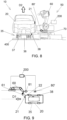
- FIGs 8 and 9 illustrate embodiments of an assembly line with an assembly unit.
- the transport of the vehicle body 20 or other part along the assembly line and past an assembly unit 50 is provided by an Automated Guided Vehicle (AGV) 35, instead of a conveyor.
- AGV Automated Guided Vehicle
- Figure 9 the AGV 35 is shown in dotted lines, as it is under the vehicle body 20.
- An AGV 35 may comprise a driving unit 36 with wheels and a carriage 37 adapted to support the vehicle body 20.
- the carriage 37 is attached to the driving unit 36 through a stem (not shown) with a freedom of movement in a vertical direction.
- Other AGVs may comprise different constructions.
- the driving unit may cause the advance of the carriage, but the carriage itself may not be mounted on the driving unit and may support the weight of the vehicle body or other part.
- the AGV 35 is configured for conveying the vehicle body 20 on the ground, for example over an irregular floor 400 in an automotive production line 10, along the advance direction (perpendicular to the paper in Figure 8 ), following elements such as markers or wires in the floor, magnets, lights, etc. (not shown).
- the assembly unit 50 comprises an additional real time vision system 80' arranged to monitor the position of the AGV 35 as it advances along the assembly line 10, wherein the output of the real time vision system 80' is also connected to the controller 200 of the robot 60 of the assembly unit 50, as shown schematically in Figure 9 .
- the real time vision system 80' is similar to vision system 80 described above, and allows tracking the movement of the AGV 35 in the intended advance direction and also in vertical direction, for example the unintended movements in the vertical direction D2 that may be caused for example by an uneven floor.
- the tracking of the AGV 35 is therefore more accurate, and vertical positioning errors of the target area 21 due to AGV oscillations, or errors in other directions, may be compensated or taken into account in the synchronisation of the robot 60 with the movement of the AGV 35, such that the robot 60 may travel on the track 70 synchronised with the advance of the AGV, and its end effector may be displaced vertically or in other directions synchronised with oscillations of the AGV.
- the AGV may be provided with an AGV marker 38 in a suitable position, such that the real time vision system 80' may track the position of the AGV marker 38.
- an AGV marker may be printed on the AGV, attached to the AGV permanently, or attached to the AGV only temporarily.
- a suitable marker 38 may also be a feature of the AGV itself, such as a hole, edge or the like.
- AGVs have more straight lines and edges than a vehicle body, and therefore have several features that are suitable to be tracked by the vision system 80'.
- the AGV may also be provided with several markers, in order to facilitate its monitoring by the vision system 80', such that there is always a marker in the field of view of the vision system 80' as the AGV advances.
- the vision system 80' is shown as arranged to travel with the robot 60 along the track 70. This arrangement of the vision system 80' is not within the scope of the appended claims.
- the real time vision system 80' is arranged stationary along the path of the AGV, i.e. along the assembly line, to monitor a marker or feature 38 of the AGV.
- the sensor 81 of the real time vision system 80 for monitoring the target area 21 or a marker 22 that moves together with the target area 21, and the sensor (not shown) of the real time vision system 80' are both connected to the robot controller 200.
- the controller 200 controls the movement and operation of the robot 60 and of its end effector 61 in at least two directions, according to the examples described above.
- the controller 200 may also receive the input of a force/torque sensor, as disclosed above.
- the vehicle body 20 is advanced on an AGV in block 1010, and in block 1020 the real time vision system 80' detects and starts monitoring the AGV 35 by a visual servoing process.
- the robot 60 is synchronised with the movement of the AGV 35: for example, robot 60 is controlled by the controller 200 to travel on the track 70 ( Figure 8 ) synchronised with the advance of the AGV 35, and the movement of the end effector 61 with respect to the base of the robot 60 is synchronised with the vertical oscillations of the AGV 35.
- the end effector of the robot 60 and the target area 21 move in parallel at approximately the same speed and with the same vertical oscillation, and therefore maintaining a constant mutual position, except for the positioning errors between each vehicle body and AGV.
- the end effector 61 of the robot is moved towards the position of the target area 21 at a relatively fast speed, and to a relatively accurate position, by virtue of the visual servoing control of the movement of the AGV, such that the target area 21, or the marker 22, come in the field of vision of the vision sensor 81.
- the position of this target area may be determined by taking a general image of the part, as explained in block 740 of Figure 7 ; however, in some cases this step may be omitted.
- a visual servoing process may then be launched in block 1050, and a compliant behaviour process in block 1060, as discussed above for Figures 6 and 7 .
- Monitoring of the AGV movement by the real time vision system 80' and synchronisation of the robot with the AGV movement as in blocks 1020, 1030 may continue during the visual servoing and compliant behaviour processes of blocks 1050 and 1060.
- the outputs of the two systems may be combined by the controller 200 such that the movement of the end effector may be a sum of the movements of the AGV and the movements of the target part on the AGV.
- one industrial robot or several industrial robots may be employed, either working jointly, synchronised, or independently from each other.
- they may each have an associated vision system, or they may all be controlled using data from the same vision system.
- an "industrial robot” is an automatically controlled, reprogrammable multipurpose manipulator that is programmable in three or more axes, in accordance with the definition of ISO Standard 8373.
- Examples of commercial industrial robots that may be employed in an assembly line such as disclosed herein may be models IRB 4600, IRB 6700, IRB 7600, etc., all available from ABB, Zurich, Switzerland ( www.abb.com ).
- Different end effectors to be operated by an industrial robot may be mounted on the wrist of the robot: for example, grippers for handling an assembly element to be mounted on a part such as a vehicle body in an assembly line, tools such as a welding tool, etc.
- the robots may be directly fixed to a floor through the robot base or it may be mounted on a supporting structure, roof mounted, mounted on a track, etc.
Landscapes
- Engineering & Computer Science (AREA)
- Mechanical Engineering (AREA)
- Physics & Mathematics (AREA)
- Robotics (AREA)
- Automation & Control Theory (AREA)
- General Physics & Mathematics (AREA)
- Remote Sensing (AREA)
- Radar, Positioning & Navigation (AREA)
- Aviation & Aerospace Engineering (AREA)
- Transportation (AREA)
- Electromagnetism (AREA)
- Multimedia (AREA)
- Computer Vision & Pattern Recognition (AREA)
- Combustion & Propulsion (AREA)
- Chemical & Material Sciences (AREA)
- Manufacturing & Machinery (AREA)
- Manipulator (AREA)
- Automatic Assembly (AREA)
Description
- The present application claims the benefit and priority of
EP18382065.3 filed on February 6, 2018 - The present disclosure is related to a method for assembling parts in an assembly line, such as an automotive final assembly line, to an assembly unit, and also to assembly lines.
- Automotive production lines for manufacturing vehicle bodies usually include a final assembly line where human operators and/or robots may operate to assemble parts such as seats, doors, windshield, wheels, steering mechanisms, etc. Vehicle bodies are usually advanced continuously along the assembly line by suitable transport means, such as a conveyor or AGVs (Automated Guided Vehicles).
- An assembly robot for such an assembly line comprises an end effector carrying a tool or carrying an assembly element to be attached or mounted to the vehicle body, and the end effector of the robot is controlled to perform a certain operation in a target position of the vehicle body. In some case the robot may be driven on tracks parallel to the assembly line.
- However, robot automation has not yet been able to replace human operators to a large extent in this kind of applications: in final assembly lines there are several sources of errors, tolerances and inaccuracies, for example arising from the continuous motion of the parts, e.g. vehicle bodies, in the line, that may be irregular, for example subject to vibrations. This makes it difficult for robots, which generally run on predetermined programs, to work efficiently.
-
US20060167587 discloses an assembly line wherein a vehicle body is advanced continuously by a conveyor. A digital encoder is provided on an axle of the conveyor drive and the end effector of an assembly robot is controlled to track the movement of the conveyor, adopting a position that is effectively stationary with respect to the vehicle body. To correct errors due to the conveyor vibration with respect to the conveyor drive axle, the document provides an optical sensor on the conveyor, compares the frequency and amplitude of relative movement over several cycles, and synchronises the robot assembly action to the peak of conveyor movement. A robot guiding sensor, such as a measurement laser, measures the displacement that is required for the end effector to reach the target on the vehicle body. In other embodiments the vehicle body is stopped in front of the robot and the coordinates of a target point are determined using the measurement laser. - Even though this document teaches a solution for compensating errors due to the conveyor vibration, the solution involves synchronising the assembly operation to a specific and estimated point of the conveyor movement cycle, which makes it likely that the target may move between the reading of the measurement laser and the actual assembly operation.
- Furthermore in this document a compensation of errors in the position of the skid on the conveyor, and/or of the vehicle body on the skid, requires that the conveyor is stopped for determining the coordinates of points of the vehicle body. Therefore the document does not teach how to compensate this kind of errors without stopping the conveyor.
- Other sources of positioning errors, such as those due to the limited resolution of the encoder on the conveyor drive axle, are not addressed in
US20060167587 . - It would be desirable to facilitate a higher degree of robot automation in assembly lines, and particularly automotive final assembly lines, by providing a method and a system for assembling parts which at least partially overcome prior art disadvantages. For example, it would be desirable to provide solutions to perform assembly operations in motion, i.e. on a moving part, and/or to allow compensating several sources of error.
-
US2011087360 discloses an industrial robot used to assemble a part to a predetermined location on a randomly moving workpiece. The workpiece may be an automobile on an assembly line and the part may be a wheel (a tire mounted on a rim) to be assembled on one of the wheel hubs of the automobile. The robot has mounted on it a camera, a force sensor and a gripper to grip the part. After the robot grips the part, signals from both the force sensor and vision are used by a computing device to move the robot to a position where the robot can assemble the part to the predetermined location on the workpiece. -
US2013035783 discloses a vehicle carrier configured to move a vehicle along an assembly line, an assembly platform disposed adjacent to the assembly line, and a synchronizer configured to synchronize the motion of the assembly platform with the motion of the vehicle carrier as the vehicle carrier moves along a length of the assembly line, and includes a sensor, processor, and actuator. - According to a first aspect, a method for assembling parts in an assembly line, such as an automotive final assembly line, according to claim 1, is provided.
- Monitoring the movement of the AGV in at least two directions in real time and using the readings in a visual servoing control of the assembly unit, allows a very fast and accurate location of a target area of the part on which an operation has to be performed, for example even before the part has reached the area of reach of the assembly unit; furthermore the movement of the assembly unit may be synchronised with the movement of the AGV based on the first real time vision system, such that the assembly unit may work on the part as if it was stationary respect to the part, and therefore without the need to compensate for the advance of the AGV and its positioning errors, for example due to unevenness of the floor and consequent vertical vibrations of the AGV: this allows increased accuracy and/or speed in the overall operation of the assembly unit.
- The method is also safe, as for example in case of a stop of the AGV there is a lower risk of a collision between the assembly unit and the part on which the operation is performed, as the assembly unit may be synchronised in real time with the advance of the AGV.
- The combination of first and second real time vision systems has multiple advantages. The second vision system may locate a target area very fast in order to start its associated visual servoing process, as the first vision system provides accurate positioning information for each individual part travelling along the line and reaching the second vision system, such that the second vision system may have a smaller field of vision. This of course means that less time will be needed for the operation on the part.
- Furthermore, the combination of the two real time vision systems as disclosed above allows performing automated operations that a single vision system may not be able to achieve, or may be subject to errors and even to the risk of collisions.
- For example, a complex assembly operation such as mounting the cockpit in a vehicle in an automotive final assembly line is difficult to automate because it involves a robot first inserting the cockpit through an open door in the car body, and then mounting the cockpit in the correct position inside the car body. A vision system that is suitably configured and attached on the end effector of the robot for locating the target for the second operation and mounting the cockpit cannot see its target area from outside the vehicle body, and is not easily configured to safely locate the opening and the position of the door, which depends on an earlier assembly station in the line, for the first part of the operation. In such a case the readings of the first real time vision system that monitors the movement of the AGV may be used at least in a first operation or a first part of the movement of the robot or of its end effector, while the second real time vision system that monitors the position of the target area may start operating in a second operation or second part of the movement of the robot or its end effector.
- After the second real time vision system has started operating because it has located the target area, the first real time vision system may also continue operating, the outputs of the two systems being combined in the visual servoing controller arranged to control the movement of the end effector of the robot during the operation: this movement of the end effector may therefore be a sum of the movements of the AGV and the movements of the target part on the AGV.
- In operations where one of the two vision systems can locate the target area and perform the whole assembly operation, the provision of a further redundant system allows higher assembly speeds, and/or detecting e.g. positioning errors or failures of one of the systems, preventing further damage.
- A real time vision system may monitor or track the AGV in a very accurate way, such that also vertical or other positioning errors of the target area that are due to AGV oscillations may be compensated or reduced already at the level of the synchronisation of the robot and its end effector with the movement of the AGV.
- According to a second aspect, the present disclosure provides an automotive final assembly line according to claim 6.
- The first real time vision system may also be provided with two or more vision sensors: for example, two or more stationary sensors may be provided to cover all the travel path of an AGV in correspondence with an assembly unit that performs an operation on the part carried by the AGV.
- A vision sensor of the first real time vision system may be arranged to monitor one or more features or markers of an AGV: for example, a vision sensor, especially but not only a stationary vision sensor, may be arranged to first detect and monitor a marker or a feature of the leading end zone of an AGV in the direction of advance, and then another marker or feature of the trailing end zone of the AGV, as they come into the field of vision of the sensor.
- As employed in the present disclosure, visual servoing refers to a vision-based robot control method in which the degrees of freedom of the robot to perform a certain operation (e.g. inserting a hinge pin into a pinhole) are not controlled according to a predetermined program, identical for every repetition of the operation, but are controlled in real time using information provided by a vision sensor, such that the robot is progressively guided by the vision system towards the target area, and each time the operation is performed the robot may undergo different movements.
- In the present disclosure, compliant behaviour refers to a robot control method in which the robot is "soft", i.e. it is not stiff, in at least one direction of movement, such that the robot is allowed to deviate to a certain extent from an intended trajectory depending on the applied external force, e.g. if it encounters a mechanical resistance. There are several methods and techniques to control a robot with compliant behaviour, such as using a force sensor.
- In methods for assembling parts disclosed herein, the movement of the assembly robot and its end effector, which may e.g. carry an element to be assembled on the part at the target area thereof, is done by performing a visual servoing process in real time, using data from a vision system that monitors, directly or indirectly, the actual position of the target area of the vehicle body or other part.
- Such real time visual servoing based on the monitoring of the target area allows at least partly compensating errors due to tolerances in tracking the advance of the part (e.g. due to the resolution of an encoder tracking the conveyor motion), as well as errors with respect to the intended trajectory of the part due to vibrations or other uneven movement of the conveyor or other transport system, as well as errors due to differences between the CAD design of the part and the physical shape/features of the part, and positioning errors of the part on the conveyor. Furthermore, this may be achieved without stopping the advance of the part.
- In other words, the deviations from the intended trajectory, vibrations, and other inaccuracies in the positioning of the target area are addressed by the fact that the robot is guided in real time by a vision system that monitors the position of the target area of the actual part on which the assembly operation is being carried out.
- The compliant behaviour process, in combination with the visual servoing, deals safely and efficiently with small residual errors in the positioning of the end effector of the robot in the final movements of the assembly operation, when the end effector, or an assembly element held by the end effector, contacts the part.
- In some examples, the part may be advanced continuously along the assembly line, at a constant or a variable speed.
- As mentioned above, the assembly methods of the present disclosure are particularly efficient with parts that move continuously, because the visual servoing and compliant behaviour provide the ability to at least partly compensate in real time positioning errors, arising from multiple sources, between the end effector of the robot (or an assembly element carried by the end effector) and the part, and therefore the continuous advance of the part is not a major hurdle for the accuracy of the assembly operation.
- The real time vision system may comprise a vision sensor arranged to obtain images of the target area. However, it may be preferable to arrange the vision sensor to obtain images of a marker that moves together with the target area, for example a marker close to the target area. This is useful especially, but not exclusively, if the sensor is mounted to move with the end effector of the robot, as the end effector itself may hinder at some point the view of the target area by the vision sensor. A marker may also be a better solution if the target area, due to its configuration, is not easily tracked by an artificial vision system, e.g. if it lacks contrast.
- The marker may be a visible element or feature of the part itself, for example one that provides a clear, contrasted image for fast and accurate detection by the vision sensor, such as a hole in the part, an edge of an opening, or a particular shape or line. It may also be a marker in the form of a graphic symbol, barcode, QR code or the like, which may be applied on the part, or provided on a label that is then attached to the part, and in this case the marker may be provided on the part before the assembly operation and removed from the part after the assembly operation.
- In some embodiments of the method, during the compliant behaviour process the movement of the end effector of the robot is controlled at least based on the readings of a force/torque sensor mounted on the robot to detect external forces acting on the end effector.
- A force/torque sensor may be typically provided with resistance strain gauges to measure the strain applied in several degrees of freedom, for example in all six degrees of freedom (three forces and three torques), and suitable electronics to process the signals from the strain gauges and communicate with an external device, for example with the robot controller.
- Such a sensor may be inserted for example between the wrist and the end effector of the robot to detect the strain between the two elements and provide information about the external forces acting on the end effector, and therefore about the relative position between the end effector and the part on which the assembly operation is carried out.
- In some embodiments of the method, each of the visual servoing process and the compliant behaviour process are simultaneously active during the assembly operation, and the movement of the end effector results from a combination of both processes.
- For example, the end effector may be guided based on a real time vision system to converge towards a final assembly position, but this convergence is modified or softened by the compliant behaviour, for example depending on the readings of a force/torque sensor, to optimise the ability of the robot to perform the final step of the assembly operation, which is usually the more critical step, safely and efficiently.
- For example, the robot controller may receive signals from a real time vision system which are representative of a desired position of the end effector according to the vision system, and may also simultaneously receive signals from a compliant behaviour system which are representative of a desired position of the end effector according to the compliant behaviour system, and the robot controller may control the movement of the end effector based on a combination of the received signals in real time.
- At the beginning of the assembly operation, and while the end effector and the assembly element it carries are still at a distance from the target area, the signals from the compliant behaviour system will normally be zero, or negligible, because no external force is acting on the end effector.
- Consequently, in this phase the signals from the compliant behaviour system will have no effect in the combination, and the controller will move the end effector as signalled and guided by the vision system.
- However, when there is a physical interaction, i.e. contact, between the assembly element or the end effector and an external object, such as the target area or a neighbouring area, then the signals from the compliant behaviour system will not be zero. The desired position to which the end effector should move, according to the vision system, will not be the same as the desired position according to the compliant behaviour system.
- The robot controller will then combine the desired positions, for example making a weighted sum, and move the end effector accordingly. The relative weight given in the combination to the vision system and to the compliant behaviour system may depend on the specific assembly operation: e.g. more relative weight may be given to the compliant behaviour system in cases of more fragile parts, and more relative weight may be given to the vision system in cases where the time available for the assembly operation is limited.
- Thus, it will be appreciated that a visual servoing process and a compliant behaviour process may occur simultaneously, and the movement of the end effector of the robot is controlled in real time based on both the inputs of the vision system and the inputs of the compliant behaviour system.
- In some examples, once the robot is travelling synchronised with the advance of the conveyor, and before starting a visual servoing process of the assembly operation, the position of the target area of the part is determined by taking a camera capture, for example a general image of the part, and the end effector of the robot is moved towards the position of the target area, up to a predetermined distance.
- This movement may be a first approximation of the robot effector to the target area, at a relatively fast speed, i.e. at a speed that is on average faster than the speed during the visual servoing and compliant behaviour processes. In some examples, and depending on the operation, the end effector of the robot, or an assembly element held by the end effector, may be placed at a distance between 50 and 500 mm from the target area, for example a distance between 100 and 200 mm.
- Additional objects, advantages and features of embodiments will become apparent to those skilled in the art upon examination of the description, or may be learned by practice.
- Described in the following are non-limiting examples, with reference to the appended drawings. The examples shown in
Figures 1 to 7 are not within the scope of the appended claims - In the drawings:
-
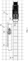
Figure 1 illustrates a simplified plan view of an assembly line with an assembly unit; -
Figure 2 is a schematic representation of an assembly line with an assembly unit similar to that ofFigure 1 ; -
Figure 3 is a block diagram of the control circuits of an assembly unit; -
Figure 4 is a flow diagram of part of a method; -
Figure 5 shows schematically an assembly unit wherein a vision system monitors a marker; -
Figures 6 and7 are flow diagrams of methods; -
Figure 8 illustrates a simplified end view of an assembly line with an assembly unit, where the assembly line comprises a transport system with AGVs; -
Figure 9 shows schematically an assembly unit wherein a first vision system monitors an AGV and a second vision system monitors a marker on a vehicle body part; and -
Figure 10 is a flow diagram of a method. - The examples disclosed with reference to
Figures 1 to 7 are not within the scope of the appended claims, but are useful to understand the claimed method and assembly line. -
Figures 1 and2 show, in plan view and schematically respectively, anassembly line 10, in the example an automotive final assembly line, which is not within the scope of the appended claims, where a part, which in this case is avehicle body 20, travels in an advance direction D1 on a transporting system such as a skid (not shown) set on aconveyor 30, past anassembly unit 50. For example, thevehicle body 20 may be transported at a continuous speed of around 100 mm/s. - The
vehicle body 20 or other part comprises atarget area 21, where an assembly operation is to be performed. Examples of assembly operations which may be performed with embodiments of the method and unit disclosed herein, may be disassembling the doors before other internal elements are inserted, assembling the vehicle cockpit, placing the carpet, placing the seats, placing the battery, placing the spare wheel, fixing the sealing joints in place by rolling, assembling the doors, etc. - A measuring device may be provided to monitor the advance of the conveyor: for example, a
digital encoder 31 may be arranged in correspondence with a drive axle (not shown) of theconveyor 30. - The
assembly unit 50 comprises anindustrial robot 60, which may comprise a controller and a number of programmable degrees of freedom or axes between a base and a wrist, each degree of freedom having an associated driving element, such as a motor, controlled by the robot controller (such details of an industrial robot are known, and not shown in the figures). - The
robot 60 is provided with acorresponding end effector 61 for example a gripper or other suitable element, attached to the robot wrist. In the example, therobot 60 is mounted on atrack 70 and provided with a suitable drive (not shown), such that it can travel parallel to the conveyor in the direction D1. - According to examples disclosed herein, the
assembly unit 50 also comprises avision system 80 with avision sensor 81, for example a camera, which may be mounted on the robot. Thevision sensor 81 may be mounted such that it moves together with theend effector 61 of therobot 60. - On
Figure 2 a number of different sources of errors and tolerances that may occur in the system have been indicated by E1, E2, E3, E4, E5, respectively representing: - E1: conveyor tracking, which may be inaccurate due to the limited encoder resolution, e.g. of +/- 2 mm;
- E2: errors arising from conveyor dynamics (vibration), due to the movement of the conveyor not being as smooth as that of the drive axle monitored by the encoder;
- E3: positioning errors between each vehicle body and the skid, and between each skid and the conveyor, and errors due to geometry differences between one vehicle body and another;
- E4: errors related to the frame rate the vision system can provide;
- E5: errors related to robot kinematics.
- As explained in the above summary, examples of assembly methods and assembly units disclosed herein allow compensating errors E1, E2 and E3 in an efficient way, as the real time visual servoing is not affected by these sources of error. Errors E3 could also be compensated with other solutions, but errors E1 and E2 are particularly difficult to compensate with known solutions. Furthermore, a compliant behaviour process allows addressing any remaining errors, such as errors E4 and E5.
-
Figure 3 is a schematic block diagram of exemplary control circuits of theassembly unit 50. - As previously disclosed, the
assembly unit 50 comprises theindustrial robot 60, which comprises theend effector 61 attached to the wrist, and thevision system 80 with the vision sensor 81 (e.g. a camera), which is mounted on the robot such that it moves together with theend effector 61. - An example of a vision sensor available on the market that is suitable for this application may be the Intel® RealSense™ Camera SR300.
- The
vision system 80, and in particular thevision sensor 81, may be arranged to monitor in real time the position of thetarget area 21 of thevehicle body 20 directly, by obtaining images of thetarget area 21 of thetarget area 21 itself, or indirectly, by obtaining images of amarker 22 that moves together with thetarget area 21, as shown in the schematic illustration ofFigure 5 . - Typically, the
marker 22 will be another point or area of thevehicle body 20, so that there is no relative movement, vibrations, etc. between thetarget area 21 and themarker 22, and is located in a position that remains in the field of view of thevision sensor 81 during the whole trajectory of theend effector 61, between an initial position and a final assembly position. - The
marker 22 may for example be a label with a graphic symbol, which is applied to a suitable point of thevehicle body 20 before the assembly operation, and usually removed afterwards. - However, it is also possible to use a visible element of the vehicle body as
marker 22, for example an element of the vehicle body with well-defined edges and sharp contrast, which is easily monitored by a computer vision system. Examples of suitable elements on a vehicle body may be a hole, the edge of a hole or opening, a line, or a particular shape. - Turning back to
Figure 3 , theassembly unit 50 may further comprise a force/torque sensor 100, for example mounted on therobot 60 between the wrist and theend effector 61, which provides readings of the external forces acting on the end effector. - The force/
torque sensor 100 may be typically provided with resistance strain gauges to measure the strain applied in several degrees of freedom, for example in all six degrees of freedom (three forces and three torques), as well as suitable electronics to process the readings from the strain gauges and provide corresponding signals to arobot controller 200 that will be described later. The signals depend on the external forces acting on the end effector, and therefore they represent the situation of physical interaction or contact between the end effector and an external part, i.e. the part on which an assembly operation is being carried out by therobot 60. - Examples of commercially available force/torque sensors that could be employed in the control of the robot in a compliant behaviour process are those of the 6-Axis Force Moment Sensor FT series available from Schunk, Germany (www.schunk.com).
- The
assembly unit 50 may further comprise animage processing module 82, avision controller module 90, a force/torque controller module 210, a real time interface torobot module 220 and therobot controller module 200 previously cited. - The
image processing module 82 may be configured to receive images of thetarget area 21 or of themarker 22 from thevision sensor 81 through a communication established between, for example, a communication sub-module comprised in theimage processing module 82 and a communication sub-module comprised in thevision sensor 81. Said communication may be secured by means of, for example, cryptographic keys and/or an SSL tunnel established between them. - Processing of the images by the
image processing module 82 may comprise: - receiving an image from the camera or
other vision sensor 81; - detecting a feature on the received image, which may be either the position and orientation of an object in the image (Position-Based Visual Servoing - PBVS) or a more abstract feature, such as points, straight lines, curve lines, etc. of the image (Image-Based Visual Servoing - IBVS);
- calculating an error between the detected feature and the same feature in a reference image, which is stored in the image processing module in an earlier learning step. In the reference image the feature is as seen by the camera when the camera is in a known position, for example at the end of the assembly operation, when the end effector of the robot completes the assembly at the target area. The error is therefore representative of the difference between the current position and the desired position of the camera, and therefore also of the difference between the current position and the desired position of the end effector;
- sending the calculated error to the
vision controller module 90. - The error is therefore calculated by comparing an image captured by the vision sensor with a reference image previously obtained in a learning process and stored in the image processing module.
- According to some examples, the
image processing module 82 may be configured to receive and process images at a frequency of at least 15 Hz, for example a frequency of at least 20 Hz. In some examples the frequency may be between 20 and 40 Hz, for example with an image being received and processed every 40-50 milliseconds (i.e. a frequency of 25-20 Hz), to allow following the target area in such a way to at least partly compensate the errors described above in relation withFigure 2 . - Furthermore, the
vision controller module 90 may be configured to: - calculate the velocity of the
camera 81 that is necessary to correct the error received from theimage processing module 82. The velocity may be calculated based on a control law, e.g.:
- convert the calculated velocity in the camera coordinate system to the coordinate system of the
end effector 61 of the robot (Tool Center Point, TCP); - calculate an increase in position ΔXVS from the velocity;
- calculate a desired position XVS of the
end effector 61 from the calculated increase in position ΔXVS and the current position XC of theend effector 61, which is received from the real time interface torobot module 220; - send the calculated desired position XVS to the real time interface to
robot module 220. - This desired position XVS may be employed for the control of the movement of the
end effector 61 of the robot, based on the readings of thevision system 80. - This process may be performed every 4 milliseconds (i.e. a frequency of 250 Hz). Said indicated time is a reference example. Since this frequency may be higher than the frequency of the
image processing module 82, thevision control module 90 will provide successive desired positions XVS, in a number of successive iterations, from the same error signal provided by the image processing module (and therefore the same calculated increase in position), but applying the increase in position to a new position XC provided by the real time interface torobot module 220, because the end effector of the robot moves at each iteration. - Basically, the
vision system 80, theimage processing module 82, thevision controller module 90, the real time interface torobot 220 and therobot controller module 200 allow executing a visual servoing process to control the movement of the end effector during the assembly operation. In this process the movement of the end effector of the robot is therefore controlled in real time based on the readings of thevision system 80. - The force/
torque controller module 210 may be configured to: - receive force and torque values from the force/
torque sensor 100; - subtract a reference value (e.g. the bending moment due to the weight of the
end effector 61 of the robot and the weight of the assembly element) from the received force value, obtaining net force and torque values; - calculate a velocity, from the net force/torque values, applying a gain and a transformation intended to allow a degree of compliant behaviour to the end effector:

- calculate an increase in position ΔXFC from the velocity;
- calculate a desired position XFC of the
end effector 61 from the calculated increase in position ΔXFC and the current position XC of theend effector 61, which is received from the real time interface torobot module 220; - send the calculated desired position XFC to the real time interface to
robot module 220. - This process may be performed every 4 milliseconds (i.e. a frequency of 250 Hz). Said indicated time is a reference example. This frequency may be the same as the frequency of the
vision control module 90, such that the real time interface torobot module 220 will receive at each iteration desired positions XVS and XFC. - The force/
torque sensor 100, the force/torque controller module 210, the real time interface torobot module 220 and therobot controller module 200 allow executing a compliant behaviour process to control the movement of the end effector during the assembly operation. In this process the movement of the end effector of the robot may therefore be controlled in real time based on the readings of theforce sensor 100. - The force-
torque sensor 100 and theforce controller module 210 may be considered a compliant behaviour system. In other examples the movement of the end effector may be controlled in real time based on different compliant behaviour systems. - In another example of a compliant behaviour system, an external sensor such as the force/
torque sensor 100 may be omitted, and the system may use as inputs for a force/torque controller module 210 (which may be part of the robot controller 200) the torques on the internal motors of the robot, which are proportional to the consumed current. An external force on the end effector, due to a physical interaction with the environment (e.g. contact with the target area) may then be detected by a variation of the torques with respect to an internal dynamic model of the robot. A control law and gain may then be applied, as described above, in order to calculate a desired velocity in order to make the end effector compliant in at least one direction. - In a further example, a compliant behaviour system may be passive: for example, a mechanical flotation system may be foreseen, where the end effector is not mounted rigid on the wrist, but with the interposition of spring elements or the like, such that if it contacts an object, its behaviour is relatively compliant, depending on the elastic features of the mounting. In this case, in a compliant behaviour process of the assembly operation the end effector is controlled based on the vision system only, but certain deviations from the intended path are allowed, due to the floating mounting, in response to a physical interaction of the end effector with an object of the environment.
- Other compliant behaviour systems may combine more than one solution: for example it may comprise a force/torque control module and also a mechanical flotation system for the end effector.
- The real time interface to
robot module 220 may be configured to: - receive the desired positions XFC and XVS generated by the force/
torque controller module 210 and thevision controller module 90; - combine the received desired positions XFC and XVS by means of an average, a weighted sum, or other, to obtain a resulting desired position XD;
- send the desired position XD to the
robot controller module 200. - The resulting desired position XD depends inter alia on the gains applied by the force/
torque controller module 210 and thevision controller module 90. The gains may be adapted to each specific assembly operation or to each phase of an assembly operation: for example, the gain applied to the force/torque controller module 210 may be higher when the parts involved in the assembly operation are particularly fragile, to give more weight to the compliant behaviour component and avoid the risk of damaging the parts, even if this may make the operation slower, because the trajectory set by the vision system may not be followed so closely. - The
robot controller module 200 may be configured to receive the desired position XD from the real time interface torobot module 220 and act on the motors or any other driving element of therobot 60 to move theend effector 61 to the desired position XD. - The
robot controller module 200 and the real time interface torobot module 220 may be the same module or not, that is, the real time interface torobot module 220 may be external or not to therobot controller module 200. - On the other hand, the expression "robot controller" may be used herein as comprising both
modules vision controller module 90, theforce controller module 210, etc. - All the errors, velocities, increment of positions ΔXFC and ΔXVS, current position Xc and desired positions XFC, Xvs, XD are vectorial variables, which include displacements and rotations with respect to one or more coordinate systems. The gains may also be vectorial variables.
- Furthermore, even though the above description has been made of a case in which the force/
torque controller module 210 and thevision controller module 90 determine desired positions from increments of position, and increments of positions from velocities, and the desired positions are then combined, other systems may work combining velocities, or increments of positions, or combining e.g. positions and increments of positions or velocities. In some cases, for example if the combination is made in the real time interface torobot module 220 with velocities or increments of positions, there is no need to provide the current position Xc to thevision controller module 90 and theforce controller module 210. - If the different circuits of
Figure 3 , for example theimage processing module 82 and thevision sensor 81, are close enough to each other, they may be wired (for example, through Ethernet technology) or may be connected through short-range wireless communication technologies, for example, Bluetooth (e.g. BLE - Bluetooth Low Energy), NFC, Zigbee or WiFi technology. If they are distant, they may be connected through long-range wireless communication technologies such as GSM, GPRS, 3G, 4G or satellite technology or wired technologies (for example, through optical fiber, ADSL, etc.). - Any of the modules disclosed with reference to
Figure 3 may comprise or may be implemented by electronic means, computing means or a combination of them, that is, said electronic or computing means may be used interchangeably so that a part of the described means may be electronic means and the other part may be computing means, or all described means may be electronic means or all described means may be computing means. -
Figure 4 is a flow diagram to schematically illustrate how a visual servoing process and a compliant behaviour process operate during an assembly operation with an assembly unit that is provided with a real time vision system and a compliant behaviour system such as described above in relation toFigure 3 , which is not within the scope of the appended claims. - In this example of the method for assembling parts, an image of the target area, or of a marker, is obtained in
block 510. - In
block 520, an error is calculated between the obtained image and a reference. - In
block 530 the desired position XVS for the vision system is determined, as a function of the error and the current position XC. - At the same time, the forces on the end effector are sensed in
block 540, and inblock 550 the desired position XFC for the compliant behaviour system is determined, as a function of the sensed forces and the current position XC. - In block 560 a combined desired position XD is calculated, based on Xvs and XFC.
- This desired positon XD is used in
block 570 to move the end effector of the robot accordingly. - In block 580 a determination is made as to whether the assembly operation has been completed. In the affirmative, the operation ends; otherwise the current position of the end effector Xc is fed to
blocks - The operations in
blocks - In practice, while the external force on the end effector, obtained from the force sensed in
block 540, is zero or negligible, the method is in an approaching step to the target area, performing a visual servoing process where the movement of the end effector is based on the desired position XVS for the vision system. - When the external force on the end effector, obtained from the force sensed in
block 540, is not zero or negligible, the method is in a step of physical interaction with the target area, performing a visual servoing process simultaneously to a compliant behaviour process, where the movement of the end effector is based on the combination of the desired position XVS for the vision system and the desired position XFC for the compliant behaviour system, as explained above in relation withFigure 3 . -
Figure 6 illustrates a flow diagram of an example of a method, not within the scope of the appended claims, for assembling parts in an assembly line: for example, for assembling a door on avehicle body 20. - In block 610 a part, such as a
vehicle body 20, is advanced in an assembly line, and inblock 620 an assembly operation is started under the control of therobot controller 200. - The
robot controller 200 may control theend effector 61 in real time to perform a desired assembly operation at thetarget area 21 of thevehicle body 20 while the vehicle body is advancing, with at least a visual servoing process represented byblock 630 and a compliant behaviour process represented byblock 640. Thecompliant behaviour process 640 may start for example once it is detected that an assembly element held by the end effector is in contact with, or very near, the target area of the vehicle body. - In the
visual servoing process 630 thecontroller 200 controls the movement of theend effector 61 based on the readings ofvision system 80, which as explained above provides signals related to the position of thetarget area 21. - In the
compliant behaviour process 640 thecontroller 200 controls the movement of theend effector 61 at least to allow a degree of compliant behaviour in at least one direction, for example depending on the signals from the force/moment sensor 100. However, the readings of thevision system 80 may also continue to affect the movement of the end effector during this step. - The
steps end effector 61 of therobot 60 from an initial position where an assembly element held by the end effector is at a distance from the target area, towards a final position in which the assembly operation is completed: for example, a door held by the end effector is mounted on the vehicle body, for example by inserting one or two hinge pins in corresponding hinge bushings of the vehicle body. - The method may comprise more than one visual servoing process or compliant behaviour process, and these processes may be alternate and/or simultaneous: for example, once the assembly element (the hinge pin of a door, for example) reaches the target area and there is contact with the vehicle body (with the hinge bushing of the door on the vehicle body, for example), the
robot controller 200 still maintains a visual servoing process to guide the final movements of the end effector, but a compliant behaviour process is also operated in order to correct or allow deviation from the movements intended by the visual servoing control, for example by combining the signals from the vision system and the compliant behaviour system as described above. - A method for assembling parts in an assembly line may comprise further steps, prior to the visual servoing and compliant behaviour processes of the example of
Figure 6 . An example of such a method, not within the scope of the appended claims, is illustrated by the flow diagram ofFigure 7 , with reference to anassembly unit 50 as shown inFigures 1 to 3 . - In
Figure 7 thevehicle body 20 is advanced on aconveyor 30 inblock 710, and inblock 720 thevehicle body 20 is referenced with respect to the conveyor's coordinate system, for example by means of a laser sensor (not shown). - In
block 730 therobot 60, with an assembly element (not shown) held by theend effector 61, is controlled to travel on thetrack 70 in the advance direction D1 of the assembly line, synchronised with the advance of theconveyor 30, which is determined by the readings ofdigital encoder 31. As a result, therobot 60 and thetarget area 21 are now moving in parallel at approximately the same speed, and therefore maintaining a constant mutual position, except for the positioning errors E1, E2 and E3 discussed above in relation withFigure 2 . - In
block 740, the position of thetarget area 21 of the part is determined by taking a general image of the part, i.e. an image from a certain distance which allows to identify the target area (or the marker, if one is used) in the part, for example by a camera capture, and inblock 750 theend effector 61 of the robot is moved towards the position of thetarget area 21 at a relatively fast speed, faster than the speed of a visual servoing process. This approximation brings the assembly element to a predetermined distance from the target area: this distance will be selected depending on the operation, the shape and size of the parts to be assembled, the accuracy required, etc. For example, it may be a distance between 50 and 500 mm from the target area. In some simple cases theend effector 61 of the robot may be moved towards the position of thetarget area 21 without the need of taking an image to determine the position of the part. - The general image will usually be taken with the same camera or
vision sensor 81 of thevision system 80, but it may also be taken with a different, dedicated camera (not shown). In other examples this step may not be necessary, or the target area may be located using simpler detectors, such as a laser detector. In further examples, the initial approximation to the target area may be done using the visual servoing process. - When a
marker 22 is employed (seeFigure 5 ), the approximation inblock 750 will also bring themarker 22 in the field of vision of thevision sensor 81. - The approximation to a
target area 21 located by a camera capture allows compensating the errors E3 discussed inFigure 2 , due e.g. to positioning errors of the vehicle body on the conveyor or to deviations between the CAD design and each individual vehicle body. - A visual servoing process may then be launched in
block 760, and a compliant behaviour process inblock 770, as discussed forblocks Figure 6 . - Control by visual servoing of the assembly operation, for example as described above in relation to
Figure 3 , allows at least partly compensating positioning errors E1, E2 described above in relation withFigure 2 . It may also compensate errors E3, if they are not compensated in a first approximation based on a camera capture, such as described above. Any residual errors are addressed by allowing compliant behaviour in the final movements of the assembly operation. -
Figures 8 and 9 illustrate embodiments of an assembly line with an assembly unit. As shown inFigure 8 , the transport of thevehicle body 20 or other part along the assembly line and past anassembly unit 50 is provided by an Automated Guided Vehicle (AGV) 35, instead of a conveyor. InFigure 9 theAGV 35 is shown in dotted lines, as it is under thevehicle body 20. - An
AGV 35 may comprise a drivingunit 36 with wheels and acarriage 37 adapted to support thevehicle body 20. Thecarriage 37 is attached to the drivingunit 36 through a stem (not shown) with a freedom of movement in a vertical direction. Other AGVs may comprise different constructions. For example the driving unit may cause the advance of the carriage, but the carriage itself may not be mounted on the driving unit and may support the weight of the vehicle body or other part. - The
AGV 35 is configured for conveying thevehicle body 20 on the ground, for example over anirregular floor 400 in anautomotive production line 10, along the advance direction (perpendicular to the paper inFigure 8 ), following elements such as markers or wires in the floor, magnets, lights, etc. (not shown). - In the example of
Figure 8 , theassembly unit 50 comprises an additional real time vision system 80' arranged to monitor the position of theAGV 35 as it advances along theassembly line 10, wherein the output of the real time vision system 80' is also connected to thecontroller 200 of therobot 60 of theassembly unit 50, as shown schematically inFigure 9 . - The real time vision system 80' is similar to
vision system 80 described above, and allows tracking the movement of theAGV 35 in the intended advance direction and also in vertical direction, for example the unintended movements in the vertical direction D2 that may be caused for example by an uneven floor. - The tracking of the
AGV 35 is therefore more accurate, and vertical positioning errors of thetarget area 21 due to AGV oscillations, or errors in other directions, may be compensated or taken into account in the synchronisation of therobot 60 with the movement of theAGV 35, such that therobot 60 may travel on thetrack 70 synchronised with the advance of the AGV, and its end effector may be displaced vertically or in other directions synchronised with oscillations of the AGV. - In order to facilitate accurate tracking of the AGV movement, the AGV may be provided with an
AGV marker 38 in a suitable position, such that the real time vision system 80' may track the position of theAGV marker 38. Such an AGV marker may be printed on the AGV, attached to the AGV permanently, or attached to the AGV only temporarily. Asuitable marker 38 may also be a feature of the AGV itself, such as a hole, edge or the like. Generally AGVs have more straight lines and edges than a vehicle body, and therefore have several features that are suitable to be tracked by the vision system 80'. - The AGV may also be provided with several markers, in order to facilitate its monitoring by the vision system 80', such that there is always a marker in the field of view of the vision system 80' as the AGV advances.
- In the example of
Figure 8 the vision system 80' is shown as arranged to travel with therobot 60 along thetrack 70. This arrangement of the vision system 80' is not within the scope of the appended claims. - In the example of
Figure 9 the real time vision system 80' is arranged stationary along the path of the AGV, i.e. along the assembly line, to monitor a marker or feature 38 of the AGV. - As shown in
Figure 9 , thesensor 81 of the realtime vision system 80 for monitoring thetarget area 21 or amarker 22 that moves together with thetarget area 21, and the sensor (not shown) of the real time vision system 80', are both connected to therobot controller 200. Based on the input of the two realtime vision systems 80 and 80' thecontroller 200 controls the movement and operation of therobot 60 and of itsend effector 61 in at least two directions, according to the examples described above. Thecontroller 200 may also receive the input of a force/torque sensor, as disclosed above. - In the example flow diagram of
Figure 10 thevehicle body 20 is advanced on an AGV inblock 1010, and inblock 1020 the real time vision system 80' detects and starts monitoring theAGV 35 by a visual servoing process. - In
block 1030 therobot 60 is synchronised with the movement of the AGV 35: for example,robot 60 is controlled by thecontroller 200 to travel on the track 70 (Figure 8 ) synchronised with the advance of theAGV 35, and the movement of theend effector 61 with respect to the base of therobot 60 is synchronised with the vertical oscillations of theAGV 35. As a result, the end effector of therobot 60 and thetarget area 21 move in parallel at approximately the same speed and with the same vertical oscillation, and therefore maintaining a constant mutual position, except for the positioning errors between each vehicle body and AGV. - In
block 1040, theend effector 61 of the robot is moved towards the position of thetarget area 21 at a relatively fast speed, and to a relatively accurate position, by virtue of the visual servoing control of the movement of the AGV, such that thetarget area 21, or themarker 22, come in the field of vision of thevision sensor 81. Optionally, before the end effector is moved towards the target area inblock 1040, the position of this target area may be determined by taking a general image of the part, as explained inblock 740 ofFigure 7 ; however, in some cases this step may be omitted. - A visual servoing process may then be launched in
block 1050, and a compliant behaviour process inblock 1060, as discussed above forFigures 6 and7 . - Monitoring of the AGV movement by the real time vision system 80' and synchronisation of the robot with the AGV movement as in
blocks blocks controller 200 such that the movement of the end effector may be a sum of the movements of the AGV and the movements of the target part on the AGV. - In examples of methods and assembly units as disclosed herein, one industrial robot or several industrial robots may be employed, either working jointly, synchronised, or independently from each other. When several robots are employed, they may each have an associated vision system, or they may all be controlled using data from the same vision system.
- In the present disclosure an "industrial robot" is an automatically controlled, reprogrammable multipurpose manipulator that is programmable in three or more axes, in accordance with the definition of ISO Standard 8373.
- Examples of commercial industrial robots that may be employed in an assembly line such as disclosed herein may be models IRB 4600, IRB 6700, IRB 7600, etc., all available from ABB, Zurich, Switzerland (www.abb.com).
- Different end effectors to be operated by an industrial robot may be mounted on the wrist of the robot: for example, grippers for handling an assembly element to be mounted on a part such as a vehicle body in an assembly line, tools such as a welding tool, etc.
- The robots may be directly fixed to a floor through the robot base or it may be mounted on a supporting structure, roof mounted, mounted on a track, etc.
- Although only a number of particular embodiments and examples have been disclosed herein, it will be understood by those skilled in the art that other alternative embodiments and/or uses of the disclosed innovation and obvious modifications and equivalents thereof are possible. The scope of the present disclosure should not be limited by particular embodiments, but should be determined only by the scope of the claims that follow.
Claims (8)
- A method for assembling parts in an assembly line, such as an automotive final assembly line (10), comprising:- advancing a part (20) along the assembly line with an Automated Guided Vehicle AGV (35), the part having a target area (21) at which an assembly operation is to be performed;- arranging a first real time vision system (80') to monitor the position of the AGV (35) in at least two directions, the first real time vision system (80') being provided with a vision sensor mounted stationary in the assembly line (10), the vision sensor of the first real time vision system (80') being configured to track the movement of the AGV (35) in an assembly line advance direction and in a vertical direction;- providing the readings of the first real time vision system (80') to a robot controller (200) arranged to control an assembly unit (50) of the assembly line to perform an automated operation on the part (20) that is advanced or supported by the AGV (35), the assembly unit (50) comprising an industrial robot (60) that is provided with an end effector (61);- arranging a second real time vision system (80) to monitor the position of the target area (21), the second real time vision system (80) comprising a vision sensor (81) mounted on the robot (60) so that it moves together with the end effector (61); wherein, while the part is advancing,- the readings of the first real time vision system (80') are provided to the robot controller (200) to synchronise the displacement of the robot or of the end effector (61) of the robot with the advance of the AGV (35) along the assembly line in the advance direction, and to synchronize the displacement of the end effector (61) of the robot (60) in the vertical direction with vertical oscillations of the AGV (35); and- the assembly operation at the target area (21) is performed with the industrial robot (60) and comprises:- a visual servoing process in which the movement of the end effector (61) of the robot (60) is controlled in real time based at least on the readings of the second real time vision system (80), and- a compliant behaviour process in which the movement of the end effector (61) of the robot (60) is controlled at least to allow compliant behaviour of the end effector (61) in at least one direction.
- A method according to claim 1, wherein a vision sensor of the first real time vision system (80') captures an image of a marker (22) or feature of the AGV (35), an image processing module of the first real time vision system (80') provides an error signal representative of the displacement of the AGV (35) based on the captured image, and the robot controller (200) controls the assembly unit (50) at least based on the error signal
- A method according to any one of the preceding claims, wherein the first real time vision system (80') is arranged to monitor the position of at least two markers (22) of the AGV (35).
- A method according to claim 3, wherein the stationary vision sensor of the first real time vision system (80') is arranged to first detect and monitor a marker (22) or a feature of the leading end zone of the AGV (35) in the direction of advance, and then another marker (22) or feature of the trailing end zone of the AGV (35), as they come into the field of vision of the sensor.
- A method according to claim 1, wherein the first real time vision system (80') is provided with two or more stationary vision sensors to cover all the travel path of an AGV (35) in correspondence with the assembly unit (50) that performs an operation on the part carried by the AGV (35).
- An automotive final assembly line (10), comprising a transport system with Automated Guided Vehicles AGVs (35) to advance parts (20) along the assembly line, an assembly unit (50), and a first real time vision system (80') provided with a vision sensor mounted stationary in the assembly line (10), to monitor the position of the AGV (35) in at least two directions, the vision sensor of the first real time vision system (80') being configured to track the movement of the AGV (35) in an assembly line advance direction and in a vertical direction, the readings of the first real time vision system (80') being provided to a robot controller (200) arranged to control an automated operation to be performed on a part (20) that is advanced or supported by the AGV (35), wherein the assembly unit (50) comprises:- an industrial robot (60) that is provided with an end effector (61),- a second real time vision system (80) arranged to monitor the position of a target area (21) of the part (20) that advances along the assembly line (10), the second real time vision system (80) comprising a vision sensor (81) mounted on the robot (60) so that it moves together with the end effector (61);- a compliant behaviour system to allow compliant behaviour of the end effector (61) in at least one direction, and- the robot controller (200) to control the movement of the end effector (61) of the robot to perform an assembly operation at the target area (21) of the part, wherein the output of the first real time vision system (80') and the output of the second real time vision system (80) are connected to the robot controller (200), and the robot controller is configured to perform an assembly operation comprising:- a displacement of the industrial robot (60), or of the end effector (61) of the robot, synchronised with the advance of the AGV (35) along the assembly line (10) in the advance direction based on the readings of the first real time vision system (80'), and a displacement of the end effector (61) of the robot in the vertical direction synchronised with vertical oscillations of the AGV (35) based on the readings of the first real time vision system (80');- a visual servoing process in which the movement of the end effector (61) of the robot is controlled in real time based on the readings of the second real time vision system (80), and- a compliant behaviour process in which the movement of the end effector (61) of the robot is controlled to allow compliant behaviour thereof.
- An automotive final assembly line according to claim 6, wherein the first real time vision system (80') comprises a vision sensor to capture an image of a marker (22) or feature of the AGV (35), and an image processing module to receive the captured image and to provide to the controller an error signal representative of the displacement of the AGV, based on the captured image.
- An automotive final assembly line according to claim 6, wherein the first real time vision system (80') is provided with two or more stationary vision sensors.
Applications Claiming Priority (2)
| Application Number | Priority Date | Filing Date | Title |
|---|---|---|---|
| EP18382065.3A EP3520971A1 (en) | 2018-02-06 | 2018-02-06 | Assembling parts in an assembly line |
| PCT/EP2019/052911 WO2019154858A1 (en) | 2018-02-06 | 2019-02-06 | Assembling parts in an assembly line |
Publications (2)
| Publication Number | Publication Date |
|---|---|
| EP3749491A1 EP3749491A1 (en) | 2020-12-16 |
| EP3749491B1 true EP3749491B1 (en) | 2023-09-13 |
Family
ID=61256876
Family Applications (2)
| Application Number | Title | Priority Date | Filing Date |
|---|---|---|---|
| EP18382065.3A Withdrawn EP3520971A1 (en) | 2018-02-06 | 2018-02-06 | Assembling parts in an assembly line |
| EP19702301.3A Active EP3749491B1 (en) | 2018-02-06 | 2019-02-06 | Assembling parts in an assembly line |
Family Applications Before (1)
| Application Number | Title | Priority Date | Filing Date |
|---|---|---|---|
| EP18382065.3A Withdrawn EP3520971A1 (en) | 2018-02-06 | 2018-02-06 | Assembling parts in an assembly line |
Country Status (5)
| Country | Link |
|---|---|
| US (1) | US11890706B2 (en) |
| EP (2) | EP3520971A1 (en) |
| CN (1) | CN111712355B (en) |
| ES (1) | ES2965233T3 (en) |
| WO (1) | WO2019154858A1 (en) |
Families Citing this family (35)
| Publication number | Priority date | Publication date | Assignee | Title |
|---|---|---|---|---|
| US11426874B2 (en) * | 2019-04-30 | 2022-08-30 | Flexiv Ltd. | Robot-based insertion mounting of workpieces |
| US11679508B2 (en) * | 2019-08-01 | 2023-06-20 | Fanuc Corporation | Robot device controller for controlling position of robot |
| GB2588630B (en) * | 2019-10-29 | 2024-03-20 | Cmr Surgical Ltd | Robotic joint control |
| US20220402136A1 (en) * | 2019-10-29 | 2022-12-22 | Abb Schweiz Ag | System and Method for Robotic Evaluation |
| US12564945B2 (en) | 2020-01-22 | 2026-03-03 | Abb Schweiz Ag | System and method for controlling the robot, electronic device and computer readable medium |
| US11514684B2 (en) * | 2020-02-07 | 2022-11-29 | Infineon Technologies Austria Ag | Dual use of safety-capable vehicle scanner for collaborative vehicle assembly and driving surveillance |
| EP3944932B1 (en) * | 2020-07-27 | 2024-09-11 | ABB Schweiz AG | A method and an assembly unit for performing assembling operations |
| JP7658071B2 (en) * | 2020-09-24 | 2025-04-08 | セイコーエプソン株式会社 | Robot control method and robot system |
| JP7851709B2 (en) * | 2020-11-18 | 2026-04-27 | ザ・ボーイング・カンパニー | Mapping device and mapping method |
| CN112757292A (en) * | 2020-12-25 | 2021-05-07 | 珞石(山东)智能科技有限公司 | Robot autonomous assembly method and device based on vision |
| EP4052859A1 (en) * | 2021-03-05 | 2022-09-07 | AyTec Automation GmbH | Conveying and mounting device for motor vehicles |
| CN112896379A (en) * | 2021-03-09 | 2021-06-04 | 矩阵数据科技(上海)有限公司 | Novel automobile assembling process |
| US12384115B2 (en) * | 2021-05-07 | 2025-08-12 | New York University | Display guided high-accuracy robotic navigation and motion control system and methods |
| WO2023272529A1 (en) * | 2021-06-29 | 2023-01-05 | 西门子(中国)有限公司 | Dynamic assembly method, apparatus, and system |
| CN113400318B (en) * | 2021-07-16 | 2023-03-24 | 四川成焊宝玛焊接装备工程有限公司 | Robot user coordinate system compensation method, automobile online edge rolling system and method |
| CN113878588B (en) * | 2021-11-12 | 2023-03-31 | 哈尔滨工业大学(深圳) | Robot compliant assembly method based on tactile feedback and oriented to buckle type connection |
| US11590616B1 (en) * | 2022-01-17 | 2023-02-28 | GM Global Technology Operations LLC | Underactuated joining system for moving assembly line |
| CN116829443A (en) * | 2022-01-27 | 2023-09-29 | 宁德时代新能源科技股份有限公司 | Vehicle final assembly production line and vehicle final assembly method |
| CN116922028B (en) * | 2022-04-08 | 2025-07-22 | 清华大学 | Automatic precise centering method and system for low-vortex long shaft of aero-engine |
| CN114881527B (en) * | 2022-06-06 | 2022-11-04 | 安徽大学江淮学院 | An online visual traceability intelligent management system for automobile intelligent assembly |
| CN115194465A (en) * | 2022-06-29 | 2022-10-18 | 格力电器(武汉)有限公司 | Air conditioner top cover assembling system and assembling method |
| CN115292540B (en) * | 2022-07-22 | 2023-06-13 | 杭州易有料科技有限公司 | Multi-mode part information identification method, device, equipment and computer readable medium |
| CN116118517A (en) * | 2022-09-09 | 2023-05-16 | 奇瑞新能源汽车股份有限公司 | Self-propelled control method and motor controller for electric vehicles |
| CN115284302A (en) * | 2022-09-14 | 2022-11-04 | 苏州征图智能科技有限公司 | A 3D visual positioning system and method suitable for dynamic assembly line of automobile instrument panel |
| CN115533473B (en) * | 2022-09-27 | 2025-05-06 | 广东沃德精密科技股份有限公司 | Automatic assembly of casing reinforcement equipment |
| CN115635481B (en) * | 2022-10-11 | 2025-09-02 | 太原理工大学 | A rapid material-picking method for mash material-picking robots based on machine vision |
| US20240311730A1 (en) * | 2023-03-13 | 2024-09-19 | GM Global Technology Operations LLC | Methods for simulating conveyor cycles on multi-product general assembly lines |
| JP7810152B2 (en) * | 2023-06-19 | 2026-02-03 | トヨタ自動車株式会社 | Detection device, position calculation system, and detection method |
| DE102023128963A1 (en) * | 2023-10-20 | 2025-04-24 | J.Schmalz Gmbh | Method for handling a gripping object by means of a handling system comprising an end effector and handling system and end effector |
| CN117549062B (en) * | 2023-11-24 | 2026-03-24 | 常州星宇车灯股份有限公司 | An automated discrete assembly system and its working method adapted to the iterative manufacturing of automotive lights |
| CN117647964B (en) * | 2024-01-29 | 2024-04-23 | 中航西飞民用飞机有限责任公司 | Cooperative follow-up mobile transfer platform control system and method for aircraft general assembly |
| CZ202452A3 (en) * | 2024-02-15 | 2025-07-30 | Ĺ KODA AUTO a.s. | Method of assembly of an automotive part |
| US20260029309A1 (en) * | 2024-07-26 | 2026-01-29 | GM Global Technology Operations LLC | Clamp monitoring systems and methods for error proofing hose clamp installation |
| CN118977247B (en) * | 2024-09-05 | 2025-12-26 | 杭州海康机器人股份有限公司 | A robot-controlled island assembly method, apparatus, and equipment |
| CN119620720B (en) * | 2024-12-17 | 2026-04-10 | 安徽江淮汽车集团股份有限公司 | Whole vehicle assembly line position safety system and control method |
Family Cites Families (9)
| Publication number | Priority date | Publication date | Assignee | Title |
|---|---|---|---|---|
| DE3851020T2 (en) * | 1987-08-27 | 1995-03-30 | Nissan Motor | Production system with unmanned, automatically guided vehicles. |
| WO1992017312A1 (en) * | 1991-04-01 | 1992-10-15 | Gmfanuc Robotics Corporation | Method and system for the flexible assembly of assemblies |
| GB0125079D0 (en) | 2001-10-18 | 2001-12-12 | Cimac Automation Ltd | Auto motion:robot guidance for manufacturing |
| KR100454714B1 (en) * | 2002-02-16 | 2004-11-05 | 한국과학기술연구원 | Working robot, actuator therefor and control method therefor |
| US9333654B2 (en) * | 2008-03-31 | 2016-05-10 | Abb Research Ltd. | Robot parts assembly on a workpiece moving on an assembly line |
| US8700205B2 (en) * | 2011-08-05 | 2014-04-15 | GM Global Technology Operations LLC | Moving stop station for robotic assembly |
| CN103264738B (en) * | 2013-06-07 | 2015-07-01 | 上海发那科机器人有限公司 | Automatic assembling system and method for vehicle windshield glass |
| CN108621156B (en) * | 2013-10-10 | 2021-08-03 | 精工爱普生株式会社 | Robot control device, robot system, robot, and robot control method |
| CN106272416B (en) * | 2016-08-29 | 2020-12-29 | 上海交通大学 | Robotic slender axis precision assembly system and method based on force sense and vision |
-
2018
- 2018-02-06 EP EP18382065.3A patent/EP3520971A1/en not_active Withdrawn
-
2019
- 2019-02-06 ES ES19702301T patent/ES2965233T3/en active Active
- 2019-02-06 EP EP19702301.3A patent/EP3749491B1/en active Active
- 2019-02-06 WO PCT/EP2019/052911 patent/WO2019154858A1/en not_active Ceased
- 2019-02-06 US US16/967,960 patent/US11890706B2/en active Active
- 2019-02-06 CN CN201980011152.2A patent/CN111712355B/en active Active
Also Published As
| Publication number | Publication date |
|---|---|
| CN111712355A (en) | 2020-09-25 |
| US11890706B2 (en) | 2024-02-06 |
| EP3520971A1 (en) | 2019-08-07 |
| ES2965233T3 (en) | 2024-04-11 |
| CN111712355B (en) | 2023-10-03 |
| EP3749491A1 (en) | 2020-12-16 |
| US20200368861A1 (en) | 2020-11-26 |
| WO2019154858A1 (en) | 2019-08-15 |
Similar Documents
| Publication | Publication Date | Title |
|---|---|---|
| US11890706B2 (en) | Assembling parts in an assembly line | |
| CN108214454B (en) | Robot system, robot control device, and robot control method | |
| US9333654B2 (en) | Robot parts assembly on a workpiece moving on an assembly line | |
| US20060167587A1 (en) | Auto Motion: Robot Guidance for Manufacturing | |
| EP3944932B1 (en) | A method and an assembly unit for performing assembling operations | |
| CN110125906B (en) | Work robot system | |
| US11628573B2 (en) | Unmanned transfer robot system | |
| CN114589487A (en) | Accurate position control for fixture-less assembly | |
| JP2020116687A (en) | Following robot and work robot system | |
| EP3904015A1 (en) | System and method for setting up a robotic assembly operation | |
| KR102934951B1 (en) | System and method for inspection advanced driver assistance system using mobile manipulator | |
| CN110271019A (en) | The control device and control method of cooperation robot | |
| CN107272693A (en) | Based on omnidirectional's car and assembly station automatic butt system and method | |
| EP4139890A1 (en) | Method and system for object tracking in robotic vision guidance | |
| EP0359822B1 (en) | Orbit controlling method of robot | |
| KR102113636B1 (en) | A car body manufacturing system using displacement sensor | |
| CN117631664A (en) | Precise moving and grabbing method for intelligent robot | |
| JPH08174454A (en) | Trajectory display device for industrial robots | |
| JP2009143293A (en) | GLASS CONVEYING DEVICE, ITS CONTROL METHOD, AND VEHICLE MANUFACTURING METHOD | |
| WO2021211547A1 (en) | Recovery system and method using multiple sensor inputs | |
| JP7846206B2 (en) | Work robot system | |
| CN116513341B (en) | Automotive Flexible Assembly Production Line System and Production Line Operation Method | |
| JP2021098249A (en) | Robot system, transport vehicle, control method for robot system, method of manufacturing article, control program, and recording medium | |
| JP2008123116A (en) | Automatic conveyance cart and control method thereof | |
| Plantenberg | Adaptive motion control for a four wheel steered mobile robot |
Legal Events
| Date | Code | Title | Description |
|---|---|---|---|
| STAA | Information on the status of an ep patent application or granted ep patent |
Free format text: STATUS: UNKNOWN |
|
| STAA | Information on the status of an ep patent application or granted ep patent |
Free format text: STATUS: THE INTERNATIONAL PUBLICATION HAS BEEN MADE |
|
| PUAI | Public reference made under article 153(3) epc to a published international application that has entered the european phase |
Free format text: ORIGINAL CODE: 0009012 |
|
| STAA | Information on the status of an ep patent application or granted ep patent |
Free format text: STATUS: REQUEST FOR EXAMINATION WAS MADE |
|
| 17P | Request for examination filed |
Effective date: 20200907 |
|
| AK | Designated contracting states |
Kind code of ref document: A1 Designated state(s): AL AT BE BG CH CY CZ DE DK EE ES FI FR GB GR HR HU IE IS IT LI LT LU LV MC MK MT NL NO PL PT RO RS SE SI SK SM TR |
|
| AX | Request for extension of the european patent |
Extension state: BA ME |
|
| DAV | Request for validation of the european patent (deleted) | ||
| DAX | Request for extension of the european patent (deleted) | ||
| STAA | Information on the status of an ep patent application or granted ep patent |
Free format text: STATUS: EXAMINATION IS IN PROGRESS |
|
| 17Q | First examination report despatched |
Effective date: 20220630 |
|
| GRAP | Despatch of communication of intention to grant a patent |
Free format text: ORIGINAL CODE: EPIDOSNIGR1 |
|
| STAA | Information on the status of an ep patent application or granted ep patent |
Free format text: STATUS: GRANT OF PATENT IS INTENDED |
|
| INTG | Intention to grant announced |
Effective date: 20230607 |
|
| GRAS | Grant fee paid |
Free format text: ORIGINAL CODE: EPIDOSNIGR3 |
|
| GRAA | (expected) grant |
Free format text: ORIGINAL CODE: 0009210 |
|
| STAA | Information on the status of an ep patent application or granted ep patent |
Free format text: STATUS: THE PATENT HAS BEEN GRANTED |
|
| AK | Designated contracting states |
Kind code of ref document: B1 Designated state(s): AL AT BE BG CH CY CZ DE DK EE ES FI FR GB GR HR HU IE IS IT LI LT LU LV MC MK MT NL NO PL PT RO RS SE SI SK SM TR |
|
| RAP3 | Party data changed (applicant data changed or rights of an application transferred) |
Owner name: ABB SCHWEIZ AG |
|
| REG | Reference to a national code |
Ref country code: CH Ref legal event code: EP |
|
| REG | Reference to a national code |
Ref country code: DE Ref legal event code: R096 Ref document number: 602019037293 Country of ref document: DE |
|
| REG | Reference to a national code |
Ref country code: IE Ref legal event code: FG4D |
|
| REG | Reference to a national code |
Ref country code: SK Ref legal event code: T3 Ref document number: E 42552 Country of ref document: SK Ref country code: LT Ref legal event code: MG9D |
|
| REG | Reference to a national code |
Ref country code: NL Ref legal event code: MP Effective date: 20230913 |
|
| PG25 | Lapsed in a contracting state [announced via postgrant information from national office to epo] |
Ref country code: GR Free format text: LAPSE BECAUSE OF FAILURE TO SUBMIT A TRANSLATION OF THE DESCRIPTION OR TO PAY THE FEE WITHIN THE PRESCRIBED TIME-LIMIT Effective date: 20231214 |
|
| PG25 | Lapsed in a contracting state [announced via postgrant information from national office to epo] |
Ref country code: SE Free format text: LAPSE BECAUSE OF FAILURE TO SUBMIT A TRANSLATION OF THE DESCRIPTION OR TO PAY THE FEE WITHIN THE PRESCRIBED TIME-LIMIT Effective date: 20230913 Ref country code: RS Free format text: LAPSE BECAUSE OF FAILURE TO SUBMIT A TRANSLATION OF THE DESCRIPTION OR TO PAY THE FEE WITHIN THE PRESCRIBED TIME-LIMIT Effective date: 20230913 Ref country code: NO Free format text: LAPSE BECAUSE OF FAILURE TO SUBMIT A TRANSLATION OF THE DESCRIPTION OR TO PAY THE FEE WITHIN THE PRESCRIBED TIME-LIMIT Effective date: 20231213 Ref country code: LV Free format text: LAPSE BECAUSE OF FAILURE TO SUBMIT A TRANSLATION OF THE DESCRIPTION OR TO PAY THE FEE WITHIN THE PRESCRIBED TIME-LIMIT Effective date: 20230913 Ref country code: LT Free format text: LAPSE BECAUSE OF FAILURE TO SUBMIT A TRANSLATION OF THE DESCRIPTION OR TO PAY THE FEE WITHIN THE PRESCRIBED TIME-LIMIT Effective date: 20230913 Ref country code: HR Free format text: LAPSE BECAUSE OF FAILURE TO SUBMIT A TRANSLATION OF THE DESCRIPTION OR TO PAY THE FEE WITHIN THE PRESCRIBED TIME-LIMIT Effective date: 20230913 Ref country code: GR Free format text: LAPSE BECAUSE OF FAILURE TO SUBMIT A TRANSLATION OF THE DESCRIPTION OR TO PAY THE FEE WITHIN THE PRESCRIBED TIME-LIMIT Effective date: 20231214 Ref country code: FI Free format text: LAPSE BECAUSE OF FAILURE TO SUBMIT A TRANSLATION OF THE DESCRIPTION OR TO PAY THE FEE WITHIN THE PRESCRIBED TIME-LIMIT Effective date: 20230913 |
|
| REG | Reference to a national code |
Ref country code: AT Ref legal event code: MK05 Ref document number: 1610798 Country of ref document: AT Kind code of ref document: T Effective date: 20230913 |
|
| PG25 | Lapsed in a contracting state [announced via postgrant information from national office to epo] |
Ref country code: NL Free format text: LAPSE BECAUSE OF FAILURE TO SUBMIT A TRANSLATION OF THE DESCRIPTION OR TO PAY THE FEE WITHIN THE PRESCRIBED TIME-LIMIT Effective date: 20230913 |
|
| PG25 | Lapsed in a contracting state [announced via postgrant information from national office to epo] |
Ref country code: IS Free format text: LAPSE BECAUSE OF FAILURE TO SUBMIT A TRANSLATION OF THE DESCRIPTION OR TO PAY THE FEE WITHIN THE PRESCRIBED TIME-LIMIT Effective date: 20240113 |
|
| REG | Reference to a national code |
Ref country code: ES Ref legal event code: FG2A Ref document number: 2965233 Country of ref document: ES Kind code of ref document: T3 Effective date: 20240411 |
|
| PG25 | Lapsed in a contracting state [announced via postgrant information from national office to epo] |
Ref country code: AT Free format text: LAPSE BECAUSE OF FAILURE TO SUBMIT A TRANSLATION OF THE DESCRIPTION OR TO PAY THE FEE WITHIN THE PRESCRIBED TIME-LIMIT Effective date: 20230913 |
|
| PG25 | Lapsed in a contracting state [announced via postgrant information from national office to epo] |
Ref country code: SM Free format text: LAPSE BECAUSE OF FAILURE TO SUBMIT A TRANSLATION OF THE DESCRIPTION OR TO PAY THE FEE WITHIN THE PRESCRIBED TIME-LIMIT Effective date: 20230913 Ref country code: RO Free format text: LAPSE BECAUSE OF FAILURE TO SUBMIT A TRANSLATION OF THE DESCRIPTION OR TO PAY THE FEE WITHIN THE PRESCRIBED TIME-LIMIT Effective date: 20230913 Ref country code: IS Free format text: LAPSE BECAUSE OF FAILURE TO SUBMIT A TRANSLATION OF THE DESCRIPTION OR TO PAY THE FEE WITHIN THE PRESCRIBED TIME-LIMIT Effective date: 20240113 Ref country code: EE Free format text: LAPSE BECAUSE OF FAILURE TO SUBMIT A TRANSLATION OF THE DESCRIPTION OR TO PAY THE FEE WITHIN THE PRESCRIBED TIME-LIMIT Effective date: 20230913 Ref country code: AT Free format text: LAPSE BECAUSE OF FAILURE TO SUBMIT A TRANSLATION OF THE DESCRIPTION OR TO PAY THE FEE WITHIN THE PRESCRIBED TIME-LIMIT Effective date: 20230913 Ref country code: PT Free format text: LAPSE BECAUSE OF FAILURE TO SUBMIT A TRANSLATION OF THE DESCRIPTION OR TO PAY THE FEE WITHIN THE PRESCRIBED TIME-LIMIT Effective date: 20240115 |
|
| PG25 | Lapsed in a contracting state [announced via postgrant information from national office to epo] |
Ref country code: PL Free format text: LAPSE BECAUSE OF FAILURE TO SUBMIT A TRANSLATION OF THE DESCRIPTION OR TO PAY THE FEE WITHIN THE PRESCRIBED TIME-LIMIT Effective date: 20230913 |
|
| REG | Reference to a national code |
Ref country code: DE Ref legal event code: R097 Ref document number: 602019037293 Country of ref document: DE |
|
| PG25 | Lapsed in a contracting state [announced via postgrant information from national office to epo] |
Ref country code: DK Free format text: LAPSE BECAUSE OF FAILURE TO SUBMIT A TRANSLATION OF THE DESCRIPTION OR TO PAY THE FEE WITHIN THE PRESCRIBED TIME-LIMIT Effective date: 20230913 |
|
| PLBE | No opposition filed within time limit |
Free format text: ORIGINAL CODE: 0009261 |
|
| STAA | Information on the status of an ep patent application or granted ep patent |
Free format text: STATUS: NO OPPOSITION FILED WITHIN TIME LIMIT |
|
| PG25 | Lapsed in a contracting state [announced via postgrant information from national office to epo] |
Ref country code: DK Free format text: LAPSE BECAUSE OF FAILURE TO SUBMIT A TRANSLATION OF THE DESCRIPTION OR TO PAY THE FEE WITHIN THE PRESCRIBED TIME-LIMIT Effective date: 20230913 |
|
| 26N | No opposition filed |
Effective date: 20240614 |
|
| PG25 | Lapsed in a contracting state [announced via postgrant information from national office to epo] |
Ref country code: MC Free format text: LAPSE BECAUSE OF FAILURE TO SUBMIT A TRANSLATION OF THE DESCRIPTION OR TO PAY THE FEE WITHIN THE PRESCRIBED TIME-LIMIT Effective date: 20230913 |
|
| REG | Reference to a national code |
Ref country code: CH Ref legal event code: PL |
|
| PG25 | Lapsed in a contracting state [announced via postgrant information from national office to epo] |
Ref country code: LU Free format text: LAPSE BECAUSE OF NON-PAYMENT OF DUE FEES Effective date: 20240206 |
|
| PG25 | Lapsed in a contracting state [announced via postgrant information from national office to epo] |
Ref country code: CH Free format text: LAPSE BECAUSE OF NON-PAYMENT OF DUE FEES Effective date: 20240229 |
|
| PG25 | Lapsed in a contracting state [announced via postgrant information from national office to epo] |
Ref country code: SI Free format text: LAPSE BECAUSE OF FAILURE TO SUBMIT A TRANSLATION OF THE DESCRIPTION OR TO PAY THE FEE WITHIN THE PRESCRIBED TIME-LIMIT Effective date: 20230913 |
|
| PG25 | Lapsed in a contracting state [announced via postgrant information from national office to epo] |
Ref country code: SI Free format text: LAPSE BECAUSE OF FAILURE TO SUBMIT A TRANSLATION OF THE DESCRIPTION OR TO PAY THE FEE WITHIN THE PRESCRIBED TIME-LIMIT Effective date: 20230913 Ref country code: LU Free format text: LAPSE BECAUSE OF NON-PAYMENT OF DUE FEES Effective date: 20240206 Ref country code: CH Free format text: LAPSE BECAUSE OF NON-PAYMENT OF DUE FEES Effective date: 20240229 |
|
| PG25 | Lapsed in a contracting state [announced via postgrant information from national office to epo] |
Ref country code: BG Free format text: LAPSE BECAUSE OF FAILURE TO SUBMIT A TRANSLATION OF THE DESCRIPTION OR TO PAY THE FEE WITHIN THE PRESCRIBED TIME-LIMIT Effective date: 20230913 |
|
| PG25 | Lapsed in a contracting state [announced via postgrant information from national office to epo] |
Ref country code: BG Free format text: LAPSE BECAUSE OF FAILURE TO SUBMIT A TRANSLATION OF THE DESCRIPTION OR TO PAY THE FEE WITHIN THE PRESCRIBED TIME-LIMIT Effective date: 20230913 |
|
| REG | Reference to a national code |
Ref country code: BE Ref legal event code: MM Effective date: 20240229 |
|
| PG25 | Lapsed in a contracting state [announced via postgrant information from national office to epo] |
Ref country code: BE Free format text: LAPSE BECAUSE OF NON-PAYMENT OF DUE FEES Effective date: 20240229 |
|
| PG25 | Lapsed in a contracting state [announced via postgrant information from national office to epo] |
Ref country code: IE Free format text: LAPSE BECAUSE OF NON-PAYMENT OF DUE FEES Effective date: 20240206 |
|
| PG25 | Lapsed in a contracting state [announced via postgrant information from national office to epo] |
Ref country code: IE Free format text: LAPSE BECAUSE OF NON-PAYMENT OF DUE FEES Effective date: 20240206 Ref country code: BE Free format text: LAPSE BECAUSE OF NON-PAYMENT OF DUE FEES Effective date: 20240229 |
|
| PGFP | Annual fee paid to national office [announced via postgrant information from national office to epo] |
Ref country code: ES Payment date: 20250331 Year of fee payment: 7 |
|
| PG25 | Lapsed in a contracting state [announced via postgrant information from national office to epo] |
Ref country code: CY Free format text: LAPSE BECAUSE OF FAILURE TO SUBMIT A TRANSLATION OF THE DESCRIPTION OR TO PAY THE FEE WITHIN THE PRESCRIBED TIME-LIMIT; INVALID AB INITIO Effective date: 20190206 |
|
| PG25 | Lapsed in a contracting state [announced via postgrant information from national office to epo] |
Ref country code: HU Free format text: LAPSE BECAUSE OF FAILURE TO SUBMIT A TRANSLATION OF THE DESCRIPTION OR TO PAY THE FEE WITHIN THE PRESCRIBED TIME-LIMIT; INVALID AB INITIO Effective date: 20190206 |
|
| PG25 | Lapsed in a contracting state [announced via postgrant information from national office to epo] |
Ref country code: TR Free format text: LAPSE BECAUSE OF FAILURE TO SUBMIT A TRANSLATION OF THE DESCRIPTION OR TO PAY THE FEE WITHIN THE PRESCRIBED TIME-LIMIT Effective date: 20230913 |
|
| PGFP | Annual fee paid to national office [announced via postgrant information from national office to epo] |
Ref country code: GB Payment date: 20260220 Year of fee payment: 8 |
|
| PGFP | Annual fee paid to national office [announced via postgrant information from national office to epo] |
Ref country code: DE Payment date: 20260218 Year of fee payment: 8 |
|
| PGFP | Annual fee paid to national office [announced via postgrant information from national office to epo] |
Ref country code: IT Payment date: 20260224 Year of fee payment: 8 |
|
| PGFP | Annual fee paid to national office [announced via postgrant information from national office to epo] |
Ref country code: FR Payment date: 20260218 Year of fee payment: 8 |
|
| PGFP | Annual fee paid to national office [announced via postgrant information from national office to epo] |
Ref country code: CZ Payment date: 20260129 Year of fee payment: 8 |
|
| PGFP | Annual fee paid to national office [announced via postgrant information from national office to epo] |
Ref country code: SK Payment date: 20260204 Year of fee payment: 8 |