EP3749465B1 - Core with improved chuck interaction - Google Patents
Core with improved chuck interaction Download PDFInfo
- Publication number
- EP3749465B1 EP3749465B1 EP19759950.9A EP19759950A EP3749465B1 EP 3749465 B1 EP3749465 B1 EP 3749465B1 EP 19759950 A EP19759950 A EP 19759950A EP 3749465 B1 EP3749465 B1 EP 3749465B1
- Authority
- EP
- European Patent Office
- Prior art keywords
- core
- coating
- cof
- high cof
- winding
- Prior art date
- Legal status (The legal status is an assumption and is not a legal conclusion. Google has not performed a legal analysis and makes no representation as to the accuracy of the status listed.)
- Active
Links
Images






Classifications
-
- B—PERFORMING OPERATIONS; TRANSPORTING
- B05—SPRAYING OR ATOMISING IN GENERAL; APPLYING FLUENT MATERIALS TO SURFACES, IN GENERAL
- B05D—PROCESSES FOR APPLYING FLUENT MATERIALS TO SURFACES, IN GENERAL
- B05D5/00—Processes for applying liquids or other fluent materials to surfaces to obtain special surface effects, finishes or structures
-
- B—PERFORMING OPERATIONS; TRANSPORTING
- B29—WORKING OF PLASTICS; WORKING OF SUBSTANCES IN A PLASTIC STATE IN GENERAL
- B29C—SHAPING OR JOINING OF PLASTICS; SHAPING OF MATERIAL IN A PLASTIC STATE, NOT OTHERWISE PROVIDED FOR; AFTER-TREATMENT OF THE SHAPED PRODUCTS, e.g. REPAIRING
- B29C53/00—Shaping by bending, folding, twisting, straightening or flattening; Apparatus therefor
- B29C53/80—Component parts, details or accessories; Auxiliary operations
- B29C53/82—Cores or mandrels
- B29C53/821—Mandrels especially adapted for winding and joining
-
- B—PERFORMING OPERATIONS; TRANSPORTING
- B05—SPRAYING OR ATOMISING IN GENERAL; APPLYING FLUENT MATERIALS TO SURFACES, IN GENERAL
- B05D—PROCESSES FOR APPLYING FLUENT MATERIALS TO SURFACES, IN GENERAL
- B05D5/00—Processes for applying liquids or other fluent materials to surfaces to obtain special surface effects, finishes or structures
- B05D5/02—Processes for applying liquids or other fluent materials to surfaces to obtain special surface effects, finishes or structures to obtain a matt or rough surface
-
- B—PERFORMING OPERATIONS; TRANSPORTING
- B29—WORKING OF PLASTICS; WORKING OF SUBSTANCES IN A PLASTIC STATE IN GENERAL
- B29C—SHAPING OR JOINING OF PLASTICS; SHAPING OF MATERIAL IN A PLASTIC STATE, NOT OTHERWISE PROVIDED FOR; AFTER-TREATMENT OF THE SHAPED PRODUCTS, e.g. REPAIRING
- B29C53/00—Shaping by bending, folding, twisting, straightening or flattening; Apparatus therefor
- B29C53/80—Component parts, details or accessories; Auxiliary operations
- B29C53/82—Cores or mandrels
- B29C53/821—Mandrels especially adapted for winding and joining
- B29C53/825—Mandrels especially adapted for winding and joining for continuous winding
-
- B—PERFORMING OPERATIONS; TRANSPORTING
- B05—SPRAYING OR ATOMISING IN GENERAL; APPLYING FLUENT MATERIALS TO SURFACES, IN GENERAL
- B05D—PROCESSES FOR APPLYING FLUENT MATERIALS TO SURFACES, IN GENERAL
- B05D7/00—Processes, other than flocking, specially adapted for applying liquids or other fluent materials to particular surfaces or for applying particular liquids or other fluent materials
-
- B—PERFORMING OPERATIONS; TRANSPORTING
- B05—SPRAYING OR ATOMISING IN GENERAL; APPLYING FLUENT MATERIALS TO SURFACES, IN GENERAL
- B05D—PROCESSES FOR APPLYING FLUENT MATERIALS TO SURFACES, IN GENERAL
- B05D7/00—Processes, other than flocking, specially adapted for applying liquids or other fluent materials to particular surfaces or for applying particular liquids or other fluent materials
- B05D7/22—Processes, other than flocking, specially adapted for applying liquids or other fluent materials to particular surfaces or for applying particular liquids or other fluent materials to internal surfaces, e.g. of tubes
-
- B—PERFORMING OPERATIONS; TRANSPORTING
- B05—SPRAYING OR ATOMISING IN GENERAL; APPLYING FLUENT MATERIALS TO SURFACES, IN GENERAL
- B05D—PROCESSES FOR APPLYING FLUENT MATERIALS TO SURFACES, IN GENERAL
- B05D7/00—Processes, other than flocking, specially adapted for applying liquids or other fluent materials to particular surfaces or for applying particular liquids or other fluent materials
- B05D7/22—Processes, other than flocking, specially adapted for applying liquids or other fluent materials to particular surfaces or for applying particular liquids or other fluent materials to internal surfaces, e.g. of tubes
- B05D7/222—Processes, other than flocking, specially adapted for applying liquids or other fluent materials to particular surfaces or for applying particular liquids or other fluent materials to internal surfaces, e.g. of tubes of pipes
- B05D7/225—Coating inside the pipe
-
- B—PERFORMING OPERATIONS; TRANSPORTING
- B05—SPRAYING OR ATOMISING IN GENERAL; APPLYING FLUENT MATERIALS TO SURFACES, IN GENERAL
- B05D—PROCESSES FOR APPLYING FLUENT MATERIALS TO SURFACES, IN GENERAL
- B05D7/00—Processes, other than flocking, specially adapted for applying liquids or other fluent materials to particular surfaces or for applying particular liquids or other fluent materials
- B05D7/24—Processes, other than flocking, specially adapted for applying liquids or other fluent materials to particular surfaces or for applying particular liquids or other fluent materials for applying particular liquids or other fluent materials
-
- B—PERFORMING OPERATIONS; TRANSPORTING
- B29—WORKING OF PLASTICS; WORKING OF SUBSTANCES IN A PLASTIC STATE IN GENERAL
- B29C—SHAPING OR JOINING OF PLASTICS; SHAPING OF MATERIAL IN A PLASTIC STATE, NOT OTHERWISE PROVIDED FOR; AFTER-TREATMENT OF THE SHAPED PRODUCTS, e.g. REPAIRING
- B29C33/00—Moulds or cores; Details thereof or accessories therefor
- B29C33/38—Moulds or cores; Details thereof or accessories therefor characterised by the material or the manufacturing process
- B29C33/3842—Manufacturing moulds, e.g. shaping the mould surface by machining
-
- B—PERFORMING OPERATIONS; TRANSPORTING
- B65—CONVEYING; PACKING; STORING; HANDLING THIN OR FILAMENTARY MATERIAL
- B65H—HANDLING THIN OR FILAMENTARY MATERIAL, e.g. SHEETS, WEBS, CABLES
- B65H75/00—Storing webs, tapes, or filamentary material, e.g. on reels
- B65H75/02—Cores, formers, supports, or holders for coiled, wound, or folded material, e.g. reels, spindles, bobbins, cop tubes, cans, mandrels or chucks
-
- B—PERFORMING OPERATIONS; TRANSPORTING
- B65—CONVEYING; PACKING; STORING; HANDLING THIN OR FILAMENTARY MATERIAL
- B65H—HANDLING THIN OR FILAMENTARY MATERIAL, e.g. SHEETS, WEBS, CABLES
- B65H75/00—Storing webs, tapes, or filamentary material, e.g. on reels
- B65H75/02—Cores, formers, supports, or holders for coiled, wound, or folded material, e.g. reels, spindles, bobbins, cop tubes, cans, mandrels or chucks
- B65H75/04—Kinds or types
- B65H75/08—Kinds or types of circular or polygonal cross-section
- B65H75/10—Kinds or types of circular or polygonal cross-section without flanges, e.g. cop tubes
-
- B—PERFORMING OPERATIONS; TRANSPORTING
- B65—CONVEYING; PACKING; STORING; HANDLING THIN OR FILAMENTARY MATERIAL
- B65H—HANDLING THIN OR FILAMENTARY MATERIAL, e.g. SHEETS, WEBS, CABLES
- B65H75/00—Storing webs, tapes, or filamentary material, e.g. on reels
- B65H75/02—Cores, formers, supports, or holders for coiled, wound, or folded material, e.g. reels, spindles, bobbins, cop tubes, cans, mandrels or chucks
- B65H75/04—Kinds or types
- B65H75/08—Kinds or types of circular or polygonal cross-section
- B65H75/14—Kinds or types of circular or polygonal cross-section with two end flanges
-
- B—PERFORMING OPERATIONS; TRANSPORTING
- B65—CONVEYING; PACKING; STORING; HANDLING THIN OR FILAMENTARY MATERIAL
- B65H—HANDLING THIN OR FILAMENTARY MATERIAL, e.g. SHEETS, WEBS, CABLES
- B65H75/00—Storing webs, tapes, or filamentary material, e.g. on reels
- B65H75/02—Cores, formers, supports, or holders for coiled, wound, or folded material, e.g. reels, spindles, bobbins, cop tubes, cans, mandrels or chucks
- B65H75/18—Constructional details
-
- B—PERFORMING OPERATIONS; TRANSPORTING
- B65—CONVEYING; PACKING; STORING; HANDLING THIN OR FILAMENTARY MATERIAL
- B65H—HANDLING THIN OR FILAMENTARY MATERIAL, e.g. SHEETS, WEBS, CABLES
- B65H75/00—Storing webs, tapes, or filamentary material, e.g. on reels
- B65H75/02—Cores, formers, supports, or holders for coiled, wound, or folded material, e.g. reels, spindles, bobbins, cop tubes, cans, mandrels or chucks
- B65H75/18—Constructional details
- B65H75/185—End caps, plugs or adapters
-
- B—PERFORMING OPERATIONS; TRANSPORTING
- B65—CONVEYING; PACKING; STORING; HANDLING THIN OR FILAMENTARY MATERIAL
- B65H—HANDLING THIN OR FILAMENTARY MATERIAL, e.g. SHEETS, WEBS, CABLES
- B65H75/00—Storing webs, tapes, or filamentary material, e.g. on reels
- B65H75/02—Cores, formers, supports, or holders for coiled, wound, or folded material, e.g. reels, spindles, bobbins, cop tubes, cans, mandrels or chucks
- B65H75/18—Constructional details
- B65H75/22—Constructional details collapsible; with removable parts
-
- B—PERFORMING OPERATIONS; TRANSPORTING
- B65—CONVEYING; PACKING; STORING; HANDLING THIN OR FILAMENTARY MATERIAL
- B65H—HANDLING THIN OR FILAMENTARY MATERIAL, e.g. SHEETS, WEBS, CABLES
- B65H2701/00—Handled material; Storage means
- B65H2701/50—Storage means for webs, tapes, or filamentary material
- B65H2701/51—Cores or reels characterised by the material
- B65H2701/511—Cores or reels characterised by the material essentially made of sheet material
- B65H2701/5112—Paper or plastic sheet material
Definitions
- a core is typically mounted on a rotating expandable chuck that is inserted into each end of the core and expanded to grip the inside of the core so that the core tends not to slip relative to the chucks as torque is applied therebetween.
- the rotation of the core is achieved by means of a drive coupled to one or both of the chucks, and the core is rotated to achieve web speeds of, for example, 800 fpm to 1500 fpm (4.1 m/s to 7.6 m/s) or more.
- the chucks generate torque (rotational force) on the core as they rotate the core during a winding operation.
- Torque also can be generated by the web during an unwinding operation, and by braking tension applied to the core by the chucks or other core engaging elements.
- the winding core comprises a tubular shell of FRP, which is substantially stiffer than a paperboard tube of the same dimensions.
- the winding core also includes a pair of generally tubular end fittings bonded to the inner surface of the shell at the opposite ends, the end fittings comprising a material having a durometer hardness substantially lower than that of the shell and being positioned to be engaged by winding or unwinding chucks.
- Each end fitting has an axial length that is a relatively small fraction of the length of the shell.
- US 2 922 343 A describes coating being disposed on the inner surface along the entire length of the core.
- Coefficient of Friction As used herein, coefficient of friction generally means the frictional force between a core and the core engaging elements when the two are stationary.
- Core A cylindrical structure, usually hollow, for carrying sheet or strand material thereon.
- the core may be made of fiber (such as wound paper), plastic, metal or any suitable material. Sometimes referred to as a tube or spool.
- the cores described herein may be used to hold and dispense any suitable material, including without limitation paperboard (such as for use in making packaging, sheet grade paper, and tissue grade paper), metal sheets, plastic films and textiles.
- Chew Out Damage to the inner surface of a core caused during a winding or, especially, an unwinding operation when the core engaging elements rotate independently of the core. Chew out usually happens when maximum torque is exceeded.
- Core engaging elements The structure or structures that engage (contact) the core to hold the core during winding and unwinding operations. May include without limitation chucks, solid shafts, differential shafts and arbors, either with or without expanding elements.
- Engaging surface(s) The surface(s) on the inner surface of the core that engage (contact) the core engaging elements.
- Maximum torque The amount of torque that can be applied to a core before slippage (between the core and the core engaging elements) occurs.
- Recoiler A machine used to wind sheet material, particularly metal sheets, onto a core or spool.
- shafts In contrast to chucks, shafts generally extend through the entire length of the core to hold the core. Differential shafts are shafts having sections that can rotate at different rotational speeds.
- Torque As used herein, torque generally means the rotational force applied to a core. Torque can generated by the core engaging elements as they rotate the core during a winding operation. Torque also can be generated by the web during an unwinding operation, and by braking forces applied to the core engaging elements.
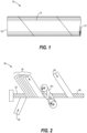
- Figure 1 a perspective view of a portion of a core 10 used for carrying material 100 thereon.
- the material 100 can be any suitable strand or sheet material such as but not limited to paper, film and textiles.
- the core 10 may comprise spirally wound paper (such as in fiber based cores) and has an inner surface 12 and an outer surface 14.
- the core 10 extends longitudinally (axially) between two ends 16 and may be any suitable length.
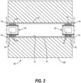
- Figure 2 a partial plan view of an apparatus 30 for making a core such as the core 10 of Figure 1 .
- the core 10 may be formed by spirally (or convolutely) winding a plurality of fiber based plies about a mandrel 32, adhering the plies together, and severing portions or sections of the continuous core as it comes off the mandrel 32 to form individual cores 10.
- the plies are drawn from respective creels (not shown) and routed along a path to the mandrel 32.
- Each ply may have an adhesive applied to it at an adhesive applying station (not shown) such as a glue pot for adhering to adjacent plies.
- a winding belt 101 may be used to rotate the continuous core 40 in a screw fashion such that the continuous core 40 advances down the mandrel 32.
- a lubricant may be applied to the inner surface of the innermost ply 34 using a lubricating station (not shown).
- the lubricant may be any suitable lubricant, including but not limited to a waxy solid, a liquid or a powder.
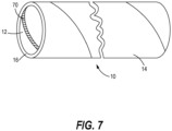
- Figure 3 is a cross-sectional side view of a portion of a paper converting apparatus 50, including a core 10 mounted on two chucks 52.
- the core 10 has an inner surface 12 that engages the chucks 52 and an outer surface 14 that carries wound material 100 such as paper, plastic film or metal foil.
- the chucks 52 are located at either end 16 of the core 10 and have expandable elements 54 (sometimes referred to as "jaws") that engage engaging surfaces 18 of the core 10.
- the engaging surfaces 18 are located at each end 16 of the core 10 and are part of the inner surface 12 of the core 10.
- Chucks come in numerous types and geometries. Some chucks are substantially cylindrical and some have cone-like extensions. As noted above, many chucks have expandable elements that engage the inner surface 12 of the core 10.
- the chucks 52 also may apply torque to the core inner surface 12 during an unwinding operation.
- the expandable elements 54 engage the engaging surfaces 18 of the core 10, applying a pressure to hold the core 10 in rotational engagement.
- the web 100 may be unwound from the core 10 via a machine driven apparatus not shown in Figure 3 .
- a brake (not shown) that acts to slow or stop the winding core 10 from rotating.
- the core 10 is typically rotated at peripheral speeds of 4.1 m/s to 7.6 m/s, although various other speeds, including much higher speeds, may be employed. It is possible that during an unwinding operation the web itself may cause torque as it is pulled off the roll.
- Figure 8 is a graph showing the relationship between maximum torque and the coefficient of friction (COF) between the core and the core engaging elements.
- the data in Figure 8 obtained using finite element analysis (FEA), shows that maximum torque increases as COF increases.
- FEA finite element analysis
- the high COF coating may be any suitable material that increases the COF of the core 10 and the core engaging elements 52.
- the coating 70 may be applied in the form of a liquid, powder, slurry or any suitable physical form.
- the coating 70 may be suitable for use with most if not all chuck designs. Suitable coatings include but are not limited to aqueous dispersions of anti-skid agents and silicates, latex coatings and adhesives.
- the coating 70 may be applied to all or a portion of the inner surface 12 of the core 10.
- the coating 70 may be applied only to the chuck engaging surface 18 near each end 16 of the core 10, or along the entire axial length of the core 10.
- Figure 16 is a flowchart illustrating a method 110 of making an improved core 10. The method may comprise the following steps:
- the coating 70 should be applied to the inner facing surface of the paper used to make the innermost plies 34.
- the coating 70 may be applied either to the inner plies 34 that make up the inner surface 12 prior to winding the plies 34 around the mandrel 32, or to the formed core inner surface 12 as the continuous core 40 moves along the mandrel 32. If applied after the core making process, that is, after the continuous core 40 is cut into usable individual cores 10, the coating 70 may be applied by any suitable means, including using a rag applicator, rollers, brushes, a squeegee applicator or a spray applicator. Preferably the coating 70 is applied near each end 16 where the chucks 52 engage the core 10.
- the coating 70 is applied on areas where the expanding core engaging elements 52 (chucks, shaft, etc.) are in contact with inside surface 12 of the core 10. In the case of chucks 52, this area generally is near each end 16 of the core 10. With shafts, this area may extend most or the entire length of the core 10. In some cases this area may be just one end 16 of the core 10 if that end experiences more torque (e.g., from a motor and/or brake).
- the expanding core engaging elements 52 chucks, shaft, etc.
- this area generally is near each end 16 of the core 10. With shafts, this area may extend most or the entire length of the core 10. In some cases this area may be just one end 16 of the core 10 if that end experiences more torque (e.g., from a motor and/or brake).
- Figure 14 is a graph showing the effect of the density of the core inner ply 34 on maximum torque. As the figure shows, in this brief set of tests, torque performance did not correlate well with density of the inner ply 34.
- Density (g/cm 3 ) 0.581 0.727 0.657 Torque (lbf-ft) 445 376 474 Torque (N-m) 602 510 643
- FIG. 15 is a graph showing the effect of paperboard strength of the core inner ply 34 on maximum torque. As the figure shows, in this brief set of tests, torque performance did not appear to correlate well with paperboard strength.
- the inner ply paper density or paperboard strength is just as important if not more so than the COF between the core 10 and the core engaging elements 52 in mitigating chewout.
- the COF between the core 10 and the core engaging elements 52 may be increased to such a high level that chuck slippage isn't the primary concern but paper failure is.
- this drastically increased level of COF - and thus maximum torque - is outside the normal operating levels in most paper converting operations.
- the inner surface 12 of the core 10 may be mechanically treated during or after the core making process, such as by mechanical abrasion to increase the roughness of the inner surface 12.
- the present disclosure relates to improved cores and methods of improving the interaction between cores and core engaging elements to reduce or eliminate damage to the core or operational problems.
- the cores and methods may be useful in numerous industries, including the paper industry (for example, with sheeting operations (fine paper, converting)), the liner industry, the sheet metal industry, and any industry involving winding or unwinding of materials carried on cores.
- COF coefficient of friction
- differential shafts are shafts having sections that can move (rotate) relative to each other.
- multiple cores are placed on the various sections of the shaft at the same time.
- the differential shaft allows relative movement between the cores, and also allows relative movement or slippage between each core and its corresponding section of the shaft.
- COF coefficient of friction
- the cores and methods described herein may offer improved performance for all chuck types, including chucks having smooth expandable elements, non-smooth expandable elements or no expandable elements.
- non-smooth expandable elements include those that are profiled, roughened or serrated.
- core engaging elements having smooth surfaces are more challenging, problems can also occur for example with elements include those that profiled, roughened or serrated.
Landscapes
- Engineering & Computer Science (AREA)
- Life Sciences & Earth Sciences (AREA)
- Wood Science & Technology (AREA)
- Mechanical Engineering (AREA)
- Manufacturing & Machinery (AREA)
- Storage Of Web-Like Or Filamentary Materials (AREA)
- Winding Of Webs (AREA)
- Unwinding Webs (AREA)
- Rolls And Other Rotary Bodies (AREA)
Description
- This patent relates to a core around which sheet or strand material can be wound. More particularly, this patent relates to a winding core having improved interaction with core engaging elements such as chucks or shafts to reduce damage to the core.
- Web materials such as polymer film, paper, nonwoven or woven textile, metal foil, sheet metal, and others, are used to manufacture a variety of products. The web materials are generally provided in the form of large rolls or coils formed by winding the web material about a winding core. The core is generally paperboard, though it may be reinforced with a plastic outer shell or the like. The paperboard core may be formed of low, medium or high strength paperboard plies.
- A roll of paper or the like wound onto the core typically has a weight above a half ton and can exceed five tons. Typical core sizes are a nominal internal diameter (ID) of 3 in. to 8 in. (76.2 mm to 203.2 mm) and a length of about 11 to 170 inches ( about 279.4 mm to 4,318 mm). Other cores, such as tissue cores and cores for carrying sheet metal, can have IDs ranging from 16 in. to 23 in. (406.4 mm to 584.2 mm).
- To begin the winding process, a leading edge of a web is attached to the winding core and the core is rotated about its axis to wind the web into a roll. The rolls are subsequently unwound during a converting or similar process.
- Web converters continually strive to increase productivity of converting processes by increasing the total amount of web throughput per unit time. To this end, there has been a continual push toward higher web speeds, roll widths and roll weights, which leads to winding cores that must rotate at higher rotational demands. Thus, paper converting can place extreme demands on the stability of current winding cores.
- During a winding or unwinding operation, a core is typically mounted on a rotating expandable chuck that is inserted into each end of the core and expanded to grip the inside of the core so that the core tends not to slip relative to the chucks as torque is applied therebetween. Typically, the rotation of the core is achieved by means of a drive coupled to one or both of the chucks, and the core is rotated to achieve web speeds of, for example, 800 fpm to 1500 fpm (4.1 m/s to 7.6 m/s) or more. The chucks generate torque (rotational force) on the core as they rotate the core during a winding operation. Torque also can be generated by the web during an unwinding operation, and by braking tension applied to the core by the chucks or other core engaging elements.
- Currently in many winding and unwinding (converting) operations, cores are used in combination with chucks that have smooth expanding elements. These smooth expanding elements do not always engage the core properly, or the maximum torque transmission is exceeded, and as a result, the chuck will break free and slip inside the core. When the slippage is excessive, the ends of the core that contact the chucks can be damaged or destroyed, the material carried on the core cannot be used, and the speed of the converting process is negatively impacted. Debris generated during unwanted slippage can also cause chuck performance and maintenance issues. Even a mild case of slippage can lead to reduced throughput, lower converting speeds and causing an excessive waste of material.
-
US 2005/184191 A1 teaches a tubular core in which the chuck-engaging surface of the core is made from a softer material than the body of the core, such that the chucks can "penetrate" ("dig in and grip") the soft chuck-engaging surface. This penetration of the chucks into the softer chuck engaging surface increases the physical engagement of the core and chucks and prevents the chuck from slipping while the core is rotating.US 2005/184191 A1 teaches using a softer layer for the mechanical engagement between the chucks and the core.US 2005/184191 A1 teaches using at least a 2 mm thick layer to allow for this improved engagement. SeeUS 2005/184191 A1 at Paragraph 0034.US 2005/184191 A1 teaches applying a softer layer of material to the entire chuck engaging surfaces. -
US 2005/098679 A1 discloses an improved core for mounting on one or more core engaging elements, the core having an inner surface and an outer surface adapted to accommodate sheet material wound thereon, the core having two axially opposed ends (seeFig. 2 ), the core comprising one or more inner plies that form engaging elements.US 2005/098679 A1 teaches a method of making a hollow cylindrical core comprising the steps of: spirally winding one or more inner plies around a forming mandrel; spirally winding one or more additional plies around the forming mandrel to form a continuous core that moves axially along the mandrel before coming off the mandrel; cutting the continuous core into individual cores, each core having two axially opposed ends, an inner surface comprising one or more engaging surfaces near each end and an outer surface adapted to accommodate a material wound therein.
US 2006/163420 A1 discloses a winding core that has high stiffness by virtue of being formed predominantly of fiber-reinforced plastic (FRP) such as fiber glass material or the like. In particular, the winding core comprises a tubular shell of FRP, which is substantially stiffer than a paperboard tube of the same dimensions. However, expandable chucks cannot readily dig into and grip the FRP shell because of its hardness. Accordingly, the winding core also includes a pair of generally tubular end fittings bonded to the inner surface of the shell at the opposite ends, the end fittings comprising a material having a durometer hardness substantially lower than that of the shell and being positioned to be engaged by winding or unwinding chucks. Each end fitting has an axial length that is a relatively small fraction of the length of the shell.
US 2 922 343 A describes coating being disposed on the inner surface along the entire length of the core.
US 2002/092284 A1 shows a method of making a hollow cylindrical core, the core having a length, comprising the steps of: spirally winding one or more inner plies around a forming mandrel, spirally winding on or more additional plies around the forming mandrel to form a continuous core that moves axially along the mandrel before coming off the mandrel, cutting the continuous core into individual cores, each core having two axially opposed ends, an inner surface comprising one or more engaging surfaces near each end, and an outer surface adapted to accommodate a material wound therein. - The present disclosure relates to an improved core for mounting on core engaging elements such as a shaft or a pair of chucks, and a method of making an improved core. The core is adapted to wind and unwind material thereon.
- The object is achieved by an improved core according to one of the
claims 1, 8 and 9 and by a method according toclaim 10. Advantageous further developments are subject-matter of the dependent claims. -
-
Figure 1 is a perspective view of a portion of a core used for carrying material thereon. -
Figure 2 is a partial plan view of an apparatus for making a core such as the core ofFigure 1 . -
Figure 3 is a cross-sectional side view of a core carrying wound material and mounted on chucks. -
Figure 4 is a perspective schematic view of one end of the core ofFigure 3 with the body portion of the chuck removed to better show the expandable elements. -
Figure 5 is a perspective end view of a core showing indentations caused by the expandable elements. -
Figure 6 is a perspective end view of a core showing damage to the inner surface of the core caused by slippage of the core with respect to the chuck. -
Figure 7 is a perspective end view of a core after a coating has been applied to the inner surface in a spiral pattern. -
Figure 8 is a graph showing the relationship between maximum torque and coefficient of friction. -
Figure 9 is a graph showing the relationship between maximum torque and coefficient of friction for a first paperboard. -
Figure 10 is a graph showing the relationship between maximum torque and coefficient of friction for a second paperboard. -
Figure 11 is a graph showing the relationship between maximum torque and concentration of high COF material. -
Figure 12 is a graph showing the relationship between maximum torque and surface area coverage. -
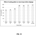
Figure 13 is a graph showing the relationship between coating pattern and maximum torque. -
Figure 14 is a graph showing the relationship between maximum torque and paperboard density. -
Figure 15 is a graph showing the relationship between maximum torque and board strength. -
Figure 16 is a flowchart illustrating a method of making an improved core according to the disclosure. - While this invention may be embodied in many forms, there is shown in the drawings and will herein be described in detail one or more embodiments with the understanding that this disclosure is to be considered an exemplification of the principles of the invention and is not intended to limit the invention as defined by the claims.
- The following definitions are intended for the ease of understanding of the disclosure and are not intended to be limiting.
- Arbor: A shaft or axle upon which a sheet may be wound.
- Coating: When used herein as a verb, the word "coating" may refer to any suitable means of applying a material onto a surface. When used herein as a noun, the word "coating" may refer to any suitable material applied to a surface, such as the inner surface of a core, including without limitation liquids, powders, compounds, mixtures and treatments.
- Coefficient of Friction (abbreviated COF, CoF or Cof): As used herein, coefficient of friction generally means the frictional force between a core and the core engaging elements when the two are stationary.
- Core: A cylindrical structure, usually hollow, for carrying sheet or strand material thereon. The core may be made of fiber (such as wound paper), plastic, metal or any suitable material. Sometimes referred to as a tube or spool. The cores described herein may be used to hold and dispense any suitable material, including without limitation paperboard (such as for use in making packaging, sheet grade paper, and tissue grade paper), metal sheets, plastic films and textiles.
- Chew Out: Damage to the inner surface of a core caused during a winding or, especially, an unwinding operation when the core engaging elements rotate independently of the core. Chew out usually happens when maximum torque is exceeded.
- Core engaging elements: The structure or structures that engage (contact) the core to hold the core during winding and unwinding operations. May include without limitation chucks, solid shafts, differential shafts and arbors, either with or without expanding elements.
- Engaging surface(s): The surface(s) on the inner surface of the core that engage (contact) the core engaging elements.
- High-COF: The term "High-COF" (or "High COF") is used herein to describe a coating or other composition that tends to increase the COF between two surfaces, such an the inner surface of a core and the core engaging elements.
- Maximum torque: The amount of torque that can be applied to a core before slippage (between the core and the core engaging elements) occurs.
- Recoiler: A machine used to wind sheet material, particularly metal sheets, onto a core or spool.
- Shafts: In contrast to chucks, shafts generally extend through the entire length of the core to hold the core. Differential shafts are shafts having sections that can rotate at different rotational speeds.
- Torque: As used herein, torque generally means the rotational force applied to a core. Torque can generated by the core engaging elements as they rotate the core during a winding operation. Torque also can be generated by the web during an unwinding operation, and by braking forces applied to the core engaging elements.
- Turning to the drawings, there is shown in
Figure 1 a perspective view of a portion of a core 10 used for carryingmaterial 100 thereon. Thematerial 100 can be any suitable strand or sheet material such as but not limited to paper, film and textiles. The core 10 may comprise spirally wound paper (such as in fiber based cores) and has aninner surface 12 and anouter surface 14. Thecore 10 extends longitudinally (axially) between two ends 16 and may be any suitable length. -
Figure 2 a partial plan view of anapparatus 30 for making a core such as thecore 10 ofFigure 1 . In general, thecore 10 may be formed by spirally (or convolutely) winding a plurality of fiber based plies about amandrel 32, adhering the plies together, and severing portions or sections of the continuous core as it comes off themandrel 32 to formindividual cores 10. The plies are drawn from respective creels (not shown) and routed along a path to themandrel 32. Each ply may have an adhesive applied to it at an adhesive applying station (not shown) such as a glue pot for adhering to adjacent plies. - In the illustrated apparatus, an
inner ply 34 is applied to themandrel 32 and spirally wound to form the inner layers of the core. Downstream from theinner ply 34, a plurality of intermediate or body plies 36 are applied on top of theinner ply 34 and spirally wound to form an intermediate zone of thecore 10. After applying the lastintermediate layer 36 and forming the intermediate zone, one or moreouter plies 38 are applied on top of the intermediate zone and spirally wound to form an outer zone of thecontinuous core 40. A cut-off station (not shown) may be included to cut thecontinuous core 40 into discrete lengths to formindividual cores 10. - A winding
belt 101 may be used to rotate thecontinuous core 40 in a screw fashion such that thecontinuous core 40 advances down themandrel 32. To facilitate movement of thecontinuous core 40 along thestationary mandrel 32, a lubricant may be applied to the inner surface of theinnermost ply 34 using a lubricating station (not shown). The lubricant may be any suitable lubricant, including but not limited to a waxy solid, a liquid or a powder. -
Figure 3 is a cross-sectional side view of a portion of apaper converting apparatus 50, including a core 10 mounted on twochucks 52. Thecore 10 has aninner surface 12 that engages thechucks 52 and anouter surface 14 that carrieswound material 100 such as paper, plastic film or metal foil. Thechucks 52 are located at either end 16 of thecore 10 and have expandable elements 54 (sometimes referred to as "jaws") that engage engagingsurfaces 18 of thecore 10. The engaging surfaces 18 are located at eachend 16 of thecore 10 and are part of theinner surface 12 of thecore 10. - Chucks come in numerous types and geometries. Some chucks are substantially cylindrical and some have cone-like extensions. As noted above, many chucks have expandable elements that engage the
inner surface 12 of thecore 10. - The
inner surface 12 is typically a paperboard material, although theinner surface 12 could be any suitable material for thecore 10. Typically, the paperboard material has a density of between about 0.58 g/cm3 to about 0.7 g/cm3, but the density can and sometimes does fall outside this range. The core 10 could be a "heterogeneous" tube wherein different materials (such as different grades of paper) form different parts (typically layers) of the core 10, or it may be a "homogeneous" tube wherein the entire core wall is formed of a single type of material, which is typical of most paperboard winding cores. - A typical outer diameter of the winding
core 10 may be about 7.025 in. (178.4 mm) and a typical inner diameter of the core 10 may be about 6.025 in. (153.0 mm). Winding cores typically come in standard diameters to accommodate uniform tooling, but it should be understood that the winding core may have various dimensions for both the inner and outer diameters of the core 10, as well as the thickness of thecore 10. The length of the core 10 in one embodiment is about 170 in. (4.32 m.), while typical core lengths range from 11 in. (239.4 mm) to 140 in. (3.56 m). However, it should be understood that the core 10 could be any suitable dimensions depending on the specific web material being wound or other factors. -
Figure 4 is a perspective schematic view of oneend 16 of thecore 10 ofFigure 3 with the body portion of thechuck 52 removed for clarity. Thechuck 52 inFigures 3 and4 includes threeexpandable elements 54. Eachexpandable element 54 is capable of expanding radially outward from the chuck body. Theexpandable elements 54 may be arranged about the entire circumference of thechuck 52. Thus, theexpandable elements 54 may be spaced uniformly about the entire inner circumference of thecore 10. - In an embodiment where the
core 10 is about 4.32 m. in length, a roll ofpaper 100 wound on the core 10 can approach a weight of 7 tons. Theexpandable elements 54 on eachchuck 52 located at the top of the core 10 support the weight of the windingcore 10 in addition to the weight of theweb material 100 that is wound on the windingcore 10 at any given time. Consequently, theexpandable elements 54 are capable of producing a substantial amount of force on the core 10 to both rotate and support the windingcore 10. - Torque may be applied to the core
inner surface 12 in a number of ways and at different times during winding and unwinding operations. In a winding operation, one or bothchucks 52 may be coupled to a motor or the like to drive the core 10 in rotation to wind theweb 100 around thecore 10. This driving action applies torque to the coreinner surface 12. - The
chucks 52 also may apply torque to the coreinner surface 12 during an unwinding operation. When unwindingmaterial 100 from the core 10 during, for example, a paper converting operation, theexpandable elements 54 engage the engagingsurfaces 18 of the core 10, applying a pressure to hold the core 10 in rotational engagement. In a paper converting operation such as that shown inFigure 3 , theweb 100 may be unwound from thecore 10 via a machine driven apparatus not shown inFigure 3 . During unwinding at least onechuck 52 is coupled to a brake (not shown) that acts to slow or stop the windingcore 10 from rotating. Thecore 10 is typically rotated at peripheral speeds of 4.1 m/s to 7.6 m/s, although various other speeds, including much higher speeds, may be employed. It is possible that during an unwinding operation the web itself may cause torque as it is pulled off the roll. - Although the
chucks 52 shown inFigure 3 includeexpandable elements 54, it should be understood that thechucks 52 could have other configurations and may alternatively not expand hydraulically, but rather expand pneumatically or mechanically inside the hollow of the core 10, as is known by those skilled in the art. Theexpandable elements 54 may also have different designs, sizes and shapes to accommodate different windingcores 10 or a specific winding/unwinding application. Different types and sizes ofchucks 52 could also be implemented for different sized windingcores 10 or for different types of winding core materials. - The
expandable elements 54 can impart very high forces on thecore 10.Figure 5 is a perspective end view of a core 10 after a partial unwinding operation. The ID (inner surface 12) of the core 10 bears visible impressions/indentations 60 caused by pressure exerted on thecore 10 by theexpandable chuck elements 54, but otherwise is basically undamaged. These indentations are a function of the radial force applied to the core 10 by theexpandable elements 54, as well as the grade, density and hardness of the paper used. - As the torque on the core
inner surface 12 increases, the likelihood of slippage between the core 10 and thechucks 52 increases. In general, many cores can withstand a torque force of 350-400 lbf-ft (475-542 Nm) and some cores can withstand much higher torque forces. Chucks have been designed to mitigate slippage by, for example, designingexpandable elements 54 to increase the contact area between theexpandable elements 54 and thecore 10 and. more particularly, the engagingsurfaces 18 of the coreinner surface 12. -
Figure 6 is a perspective end view of another core 10 after a partial unwinding operation. During the unwinding operation, torque on the core 10 increased to the point where thechuck 52 rotated independently of thecore 10 and damaged theinner surface 12 of thecore 10. - This damage may involve multiple inner plies, and is sometimes referred to as "chew out." Slippage can also result in "burnout", wherein the friction caused by the
chucks 52 against the core 10 burns or scorches thecore 10, rendering it unsuitable for further use. - When chew out (or burnout) occurs, the user can't control the web of
material 100 coming off thecore 10, which can require slowing or shutting down the paper converting operation and adjusting the core-chuck interface. Sometimes the user will place a shim or other device between the core 10 and thechucks 52 to try to eliminate further slippage, web breaks, vibration or other converting issues resulting from chuck slippage and/or core chew-out. Sometimes the user must run at a lower speed to try to avoid slippage. Also, sometimes the user will splice the web to a new roll of paper early. Repeated slippage can cause the user to splice out of rolls prematurely. - An overall method of mitigating slippage and the damage it can cause is to change the coefficient of friction (COF) between the
inner surface 12 of thecore 10 and the core engaging elements. COF, often represented by the variable µ, may be represented by the following formula:
- µ = the coefficient of friction, or COF (dimensionless);
- Ff = the frictional force exerted by one surface as it moves across another surface (in Newtons); and
- Fn = the force applied normal to the frictional force (in Newtons).
- There are two kinds of µ, static and kinetic. In the discussion that follows, µ (or COF) is generally the static µ (or static COF). It should be understood that, while the processes disclosed herein generally increase static µ, they also generally increase kinetic µ as well.
- The COF between the
inner surface 12 of thecore 10 and thechucks 52 is a function of many variables, some of which can be controlled to improve the core-chuck interaction and thus mitigate damage to thecore 10. There have been developed and will now be described various improved cores as well as methods of improving core-chuck interaction. - In one aspect a
core 10 and method of making acore 10 involves using a high COF material ("coating") 70 that is applied or otherwise disposed on theinner surface 12 of thecore 10. Thehigh COF coating 70 is adapted to increase the coefficient of friction (COF) between the inner surface of thecore 10 and the core engaging elements such as thechucks 52. Thecoating 70 may be applied over the lubricant (if present) and/or directly onto the "bare" inner surface of thecore 10. -
Figure 7 is a perspective view of a core 10 after ahigh COF coating 70 has been applied to a portion of theinner surface 12. As explained further below, thehigh COF coating 70 may be applied in any suitable pattern and to all or less than all of the engagingsurfaces 18 of thecore 10. -
Figure 8 is a graph showing the relationship between maximum torque and the coefficient of friction (COF) between the core and the core engaging elements. The data inFigure 8 , obtained using finite element analysis (FEA), shows that maximum torque increases as COF increases. - Increasing the COF between the
inner surface 12 of thecore 10 and the core engaging elements (such as chucks 52) increases maximum torque, that is, the amount of torque (rotational force) that can be applied to the core 10 by thechucks 52 before slippage occurs. In other words, adding ahigh COF coating 70 to theinner surface 12 of the core 10 causes thechucks 52 to better grip thecore 10. -
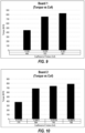
Figure 9 is a graph showing the effect of the COF (between theinner surface 12 of acore 10 and the core engaging elements 52) upon the maximum torque for a core 10 having aninner ply 34 made from a first grade of paperboard (designated "Board 1"). AsFigure 9 shows, maximum torque generally increased with the COF. Here is the same data in table form:Coefficient of Friction 0.193 0.235 0.301 Torque (lbf-ft) 445 753 827 Torque (N-m) 603 1021 1121 -
Figure 10 is a graph showing the effect of the COF (between theinner surface 12 of acore 10 and the core engaging elements 52) upon the maximum torque for a core 10 having aninner ply 34 made from a second grade of paperboard (designated "Board 2"). Again, torque generally increased with COF. Here is the same data in table form:Coefficient of Friction 0.21355 0.24471 0.29764 0.36875 Torque (lbf-ft) 376 684 740 788 Torque (N-m) 510 927 1003 1068 - The high COF coating may be any suitable material that increases the COF of the
core 10 and thecore engaging elements 52. Thecoating 70 may be applied in the form of a liquid, powder, slurry or any suitable physical form. Thecoating 70 may be suitable for use with most if not all chuck designs. Suitable coatings include but are not limited to aqueous dispersions of anti-skid agents and silicates, latex coatings and adhesives. -
Figure 11 is a graph showing the effect of the concentration of high COF material on torque, that is, the effect of the weight percent of high COF material in the coating applied to 100% of the chuck engagingsurface area 18 on torque. As the figure shows, for at least one coating / paperboard combination, increasing the concentration of the high COF material in thecoating 70 increased torque. Here is the same data in table form:Concentration of high COF 10% 20% 60% 80% Torque (lbf-ft) 1007 1050 1300 1442 Torque (N-m) 1365 1424 1763 1955 - The
coating 70 may be applied to all or a portion of theinner surface 12 of thecore 10. For example, thecoating 70 may be applied only to thechuck engaging surface 18 near eachend 16 of the core 10, or along the entire axial length of thecore 10. -
Figure 12 is a graph showing the effect of surface area on torque, and, in particular, the effect of the percent of the coreinner surface 12 that is covered withhigh COF material 70 on maximum torque. The coverage, that is, the area on which thecoating 70 is applied expressed as a percentage of the total area of the core inner surface, varied from 22% to 65%. The maximum torque varied from 1039 to 1166 Nm. As the figure shows, torque performance generally improved with surface area coverage. Here is the same data in table form:Surface Area Coverage (% core inner surface) 22% 43% 65% Torque (N-m) 1039 1076 1166 -
Figure 13 is a graph showing the relationship between coating pattern and maximum torque. As previously noted, thecoating 70 may be applied to theinner surface 12 of the core 10 in various patterns or configurations. For example, the high COF coating (70) may be applied to the inner surface (12) in a pattern to achieve a desired level of surface area coverage. Thecoating 70 may be applied in a single spiral pattern (like inFigure 7 ), a multiple spiral pattern, in one or more annular rings, or in any suitable pattern. Thecoating 70 may also be applied only to all or part of the engaging surfaces 18. - In the test results shown in
Figure 13 , coating theinner surface 12 of a core 10 with one, two or three 2,2352 cm wide spirals resulted in maximum torque values of 1039, 1076 and 1166 Nm respectively. Coating theinner surface 12 of the core 10 with one, two or three 3,81 cm wide spirals resulted in maximum torque values of 1475, 1468 and 1506 Nm respectively. Coating the entireinner surface 12 of the core 10 ("full coverage") resulted in a maximum torque value of 1542 Nm. Here is the same data in table form:Coating Pattern Spiral Width (cm) Torque (N-m) 1 spiral 2.2225 1038 2 spiral 2.2225 1076 3 spiral 2.2225 1076 1 spiral 3.81 1475 2 spiral 3.81 1468 3 spiral 3.81 1506 Full coverage 1541 -
Figure 16 is a flowchart illustrating amethod 110 of making animproved core 10. The method may comprise the following steps: -
Step 112. Spirally winding one or more inner plies (34) around a forming mandrel (32). -
Step 114. Spirally winding one or more additional plies (36, 38) around the forming mandrel (32) to form a continuous core that moves axially along the mandrel (32) before coming off the mandrel (32). -
Step 116. Cutting the continuous core intoindividual cores 10, each core (10) having two axially opposed ends (16), an inner surface (12) comprising one or more engaging surfaces near each end (16) and an outer surface (14) adapted to accommodate a material (100) wound therein. -
Step 118. Applying a high COF coating (70) onto at least a portion of the inner surface (12). - As noted above, the
core 10 may be formed by spirally winding a plurality ofplies mandrel 32, adhering the plies together to form acontinuous core 40, and severing portions or sections of thecontinuous core 40 to formindividual cores 10. Ahigh COF coating 70 is disposed on at least the engagingsurfaces 18 of the core 10 in one of several different ways. For instance, thecoating 70 may be applied before, during or after the core making process. - If applied before the core making process, the
coating 70 should be applied to the inner facing surface of the paper used to make the innermost plies 34. - If applied during the core making process, the
coating 70 may be applied either to theinner plies 34 that make up theinner surface 12 prior to winding theplies 34 around themandrel 32, or to the formed coreinner surface 12 as thecontinuous core 40 moves along themandrel 32. If applied after the core making process, that is, after thecontinuous core 40 is cut into usableindividual cores 10, thecoating 70 may be applied by any suitable means, including using a rag applicator, rollers, brushes, a squeegee applicator or a spray applicator. Preferably thecoating 70 is applied near eachend 16 where thechucks 52 engage thecore 10. - Preferably the
coating 70 is applied on areas where the expanding core engaging elements 52 (chucks, shaft, etc.) are in contact withinside surface 12 of thecore 10. In the case ofchucks 52, this area generally is near eachend 16 of thecore 10. With shafts, this area may extend most or the entire length of thecore 10. In some cases this area may be just oneend 16 of the core 10 if that end experiences more torque (e.g., from a motor and/or brake). - In another aspect the method of improving core-chuck interaction involves using a specialty material for the inner ply or plies 34 of the core 10 or the engaging
surfaces 18 of thecore 10. The specialty material can be a high COF, anti-skid paper or a paper having special properties. The special properties may include thickness, roughness and recycled paper content. - Tests were conducted to determine the effect of paper density on maximum torque.
Figure 14 is a graph showing the effect of the density of the coreinner ply 34 on maximum torque. As the figure shows, in this brief set of tests, torque performance did not correlate well with density of theinner ply 34. Here is the same data in table form:Density (g/cm3) 0.581 0.727 0.657 Torque (lbf-ft) 445 376 474 Torque (N-m) 602 510 643 - Tests were conducted to determine the effect of paperboard strength of the inner ply or plies 34 on maximum torque.
Figure 15 is a graph showing the effect of paperboard strength of the coreinner ply 34 on maximum torque. As the figure shows, in this brief set of tests, torque performance did not appear to correlate well with paperboard strength. Here is the same data in table form:Shear (lbf/in2) or psi 190 240 477 Shear (N/mm2) 1.31 1.65 3.29 Torque (lbf-ft) 445 376 474 Torque (N-m) 602 510 643 - There may be a point where the inner ply paper density or paperboard strength is just as important if not more so than the COF between the core 10 and the
core engaging elements 52 in mitigating chewout. For instance, the COF between the core 10 and thecore engaging elements 52 may be increased to such a high level that chuck slippage isn't the primary concern but paper failure is. However, it is believed that this drastically increased level of COF - and thus maximum torque - is outside the normal operating levels in most paper converting operations. - In another aspect, the method of improving core-chuck interaction involves mechanically or (not claimed) chemically treating the core inner surface or just the engaging surfaces of the core to alter the coefficient of friction (COF). For example, the method may comprise mechanically or chemically treating the engaging
surfaces 18 of a core 10 to increase the COF of the engagingsurfaces 18, thereby increasing the maximum torque between the core 10 and thecore engaging elements 52. - In one aspect, the
inner surface 12 of the core 10 may be mechanically treated during or after the core making process, such as by mechanical abrasion to increase the roughness of theinner surface 12. - In another (not claimed) aspect, the
inner surface 12 of the core 10 may be chemically treated to increase the COF of theinner surface 12 during or after thecore 10 is made. The treatment may involve chemically treating the material, such as paperboard, that forms the inner ply or plies 34 prior to making thecore 10. - In yet another aspect the method of improving core-chuck interaction involves placing or positioning a loose layer of material between the
inside surface 12 of thecore 10 and thecore engaging elements 52. In such cases the loose layer may be removed after winding. - The present disclosure relates to improved cores and methods of improving the interaction between cores and core engaging elements to reduce or eliminate damage to the core or operational problems. The cores and methods may be useful in numerous industries, including the paper industry (for example, with sheeting operations (fine paper, converting)), the liner industry, the sheet metal industry, and any industry involving winding or unwinding of materials carried on cores.
- For example, in the paper industry where cores are often mounted at either end on chucks, it may be desirable to increase the coefficient of friction (COF) between the inner surface of the core and the chucks, either by increasing the COF across the entire inner surface of the core or just at the chuck engaging surfaces.
- Likewise, in sheet metal carrying applications where Metallan™ cores are often mounted on a shaft, it may be desirable to increase the coefficient of friction (COF) along the entire inner surface of the core 10 or along less than the entire
inner surface 12, such as along just the middle portion of theinner surface 12 between the core ends 16. - In industries that employ differential winding shafts, such as certain paper, film, and tape industries, it may be desirable to adjust the coefficient of friction (COF) of each individual core to achieve a desired level of web tension for each core during winding or unwinding. Differential shafts are shafts having sections that can move (rotate) relative to each other. Typically, multiple cores are placed on the various sections of the shaft at the same time. The differential shaft allows relative movement between the cores, and also allows relative movement or slippage between each core and its corresponding section of the shaft. In these applications it may be desirable to control the COF of each core using the techniques described herein to achieve the desired level of web tension for each core during winding or unwinding.
- The cores and methods described herein may offer improved performance for all chuck types, including chucks having smooth expandable elements, non-smooth expandable elements or no expandable elements. Examples of non-smooth expandable elements include those that are profiled, roughened or serrated. While core engaging elements having smooth surfaces are more challenging, problems can also occur for example with elements include those that profiled, roughened or serrated.
- It is understood that the embodiments of the invention described above are only particular examples which serve to illustrate the principles of the invention.
- Modifications and alternative embodiments of the invention are contemplated which do not depart from the scope of the invention as defined by the appended claims. It is intended that the claims cover all such modifications and alternative embodiments that fall within their scope.
Claims (17)
- An improved core (10) for mounting on one or more core engaging elements, the core (10) adapted for winding and unwinding material (100) thereon, the core (10) being hollow and cylindrical and having an inner surface (12) and an outer surface (14) adapted to accommodate the material (100), the core (10) having two axially opposed ends (16), characterized by
a high coefficient of friction (COF) coating (70) disposed on all or a portion of the inner surface (12) in one or more spiral patterns, the high COF coating (70) adapted to increase the coefficient of friction (COF) between the inner surface (12) of the core (10) and the core engaging elements. - The core (10) of claim 1 wherein:
the high COF coating (70) is selected from the group consisting of aqueous dispersions of anti-skid agents and silicates, latex coatings, and adhesives. - The core (10) of claim 1 wherein:the high COF coating (70) comprises a high COF material; andthe weight percent of high COF material in the high COF coating is between 10% and 80%.
- The core (10) of claim 1 wherein:
the high COF coating (70) covers at least 22% of the inner surface (12). - The core (10) of claim 1 wherein:
the high COF coating (70) is applied to the inner surface (12) in a pattern to achieve a predetermined level of surface area coverage. - The core (10) of claim 1 wherein:
the one or more core engaging elements comprise a pair of chucks (52). - The core (10) of claim 1 wherein:
the one or more core engaging elements comprises a shaft extending axially through the entire core (10). - An improved fiber based core (10) for mounting on one or more core engaging elements, the core (10) adapted for winding and unwinding material (100) thereon, the core (10) having an inner surface (12) and an outer surface (14) adapted to accommodate the material (100), the core (10) having two axially opposed ends (16), the core (10) comprising one or more inner plies (34) that form the inner surface (12), the inner surface (12) comprising engaging surfaces (18) that contact the one or more engaging elements, characterized in that
the one or more inner plies (34) are made of a high COF material. - An improved core (10) for mounting on one or more core engaging elements (52), the core (10) having an inner surface (12) and an outer surface (14) adapted to accommodate sheet material (100) wound thereon, the core (10) having two axially opposed ends (16), the core (10) comprising one or more inner plies (34) that form engaging surfaces (18), wherein the improvement comprises:
the engaging surfaces (18) are mechanically treated to alter the coefficient of friction (COF) of the engaging surfaces (18) by mechanical abrasion to increase roughness. - A method (110) of making a hollow cylindrical core (10) comprising the steps of:spirally winding one or more inner plies (34) around a forming mandrel (32);spirally winding one or more additional plies (36, 38) around the forming mandrel (32) to form a continuous core that moves axially along the mandrel (32) before coming off the mandrel (32);cutting the continuous core into individual cores (10), each core (10) having two axially opposed ends (16), an inner surface (12) comprising one or more engaging surfaces near each end (16) and an outer surface (14) adapted to accommodate a material (100) wound therein; characterized byapplying a high COF coating (70) onto at least a portion of the inner surface (12) in one or more spiral patterns.
- The method (110) of claim 10 wherein:
the high COF coating (70) is applied to each of the one or more engaging surfaces. - The method (110) of claim 10 wherein:
the high COF coating (70) is applied to the inner surface (12) in the form of a single spiral pattern - The method (110) of claim 10 wherein:
the high COF coating (70) is applied to the inner surface (12) by spraying. - The method (110) of claim 10 wherein:
the high COF coating (70) is applied to the inner plies (34) before they are spirally wound around the forming mandrel (32). - The method (110) of claim 10 wherein:
the high COF coating (70) is applied to the inner surface (12) after spirally winding the inner plies (34) around the mandrel (32) and as the continuous core moves along the mandrel (32). - The method (110) of claim 10 wherein:
the high COF coating (70) is applied only to all of part of the engaging surfaces (18). - The method (110) of claim 10 wherein:
the high COF coating (70) is applied only to the middle of the inner surface (12).
Priority Applications (1)
| Application Number | Priority Date | Filing Date | Title |
|---|---|---|---|
| EP24196395.8A EP4464636A3 (en) | 2018-03-02 | 2019-02-28 | Core with improved chuck interaction |
Applications Claiming Priority (2)
| Application Number | Priority Date | Filing Date | Title |
|---|---|---|---|
| US201862637480P | 2018-03-02 | 2018-03-02 | |
| PCT/US2019/019949 WO2019169072A1 (en) | 2018-03-02 | 2019-02-28 | Core with improved chuck interaction |
Related Child Applications (2)
| Application Number | Title | Priority Date | Filing Date |
|---|---|---|---|
| EP24196395.8A Division EP4464636A3 (en) | 2018-03-02 | 2019-02-28 | Core with improved chuck interaction |
| EP24196395.8A Division-Into EP4464636A3 (en) | 2018-03-02 | 2019-02-28 | Core with improved chuck interaction |
Publications (3)
| Publication Number | Publication Date |
|---|---|
| EP3749465A1 EP3749465A1 (en) | 2020-12-16 |
| EP3749465A4 EP3749465A4 (en) | 2021-11-03 |
| EP3749465B1 true EP3749465B1 (en) | 2025-04-09 |
Family
ID=67768392
Family Applications (2)
| Application Number | Title | Priority Date | Filing Date |
|---|---|---|---|
| EP19759950.9A Active EP3749465B1 (en) | 2018-03-02 | 2019-02-28 | Core with improved chuck interaction |
| EP24196395.8A Pending EP4464636A3 (en) | 2018-03-02 | 2019-02-28 | Core with improved chuck interaction |
Family Applications After (1)
| Application Number | Title | Priority Date | Filing Date |
|---|---|---|---|
| EP24196395.8A Pending EP4464636A3 (en) | 2018-03-02 | 2019-02-28 | Core with improved chuck interaction |
Country Status (12)
| Country | Link |
|---|---|
| US (2) | US11279077B2 (en) |
| EP (2) | EP3749465B1 (en) |
| CN (2) | CN117819308A (en) |
| CA (1) | CA3092665C (en) |
| DK (1) | DK3749465T3 (en) |
| ES (1) | ES3026227T3 (en) |
| FI (1) | FI3749465T3 (en) |
| MX (2) | MX2020009160A (en) |
| MY (1) | MY205601A (en) |
| PL (1) | PL3749465T3 (en) |
| RU (1) | RU2748700C1 (en) |
| WO (1) | WO2019169072A1 (en) |
Families Citing this family (2)
| Publication number | Priority date | Publication date | Assignee | Title |
|---|---|---|---|---|
| WO2019169072A1 (en) * | 2018-03-02 | 2019-09-06 | Sonoco Development, Inc. | Core with improved chuck interaction |
| US11518645B2 (en) * | 2021-03-15 | 2022-12-06 | Sonoco Development, Inc. | Lightweight paper tube structure capable of high loading |
Citations (3)
| Publication number | Priority date | Publication date | Assignee | Title |
|---|---|---|---|---|
| US2922343A (en) * | 1958-01-10 | 1960-01-26 | Sonoco Products Co | Means for forming a spiral wound paper tube structure |
| US20020092284A1 (en) * | 2000-09-16 | 2002-07-18 | Hartwig Basse | Core for a spinning bobbin and method of producing the core |
| US20060163420A1 (en) * | 2004-12-06 | 2006-07-27 | Sonoco Development, Inc. | High-stiffness winding core |
Family Cites Families (25)
| Publication number | Priority date | Publication date | Assignee | Title |
|---|---|---|---|---|
| US1122627A (en) | 1913-04-05 | 1914-12-29 | Samuel Milne | Expanding reel bar or core for use in winding and unwinding paper, cloth, and like material. |
| US3002433A (en) * | 1958-01-10 | 1961-10-03 | Sonoco Products Co | Spiral wound paper tube having seamless outer surface |
| US3070281A (en) | 1960-11-02 | 1962-12-25 | Sonoco Products Co | Foam coated paper tube |
| US3432112A (en) | 1967-08-10 | 1969-03-11 | Sonoco Products Co | Expansible chuck for tubular core |
| US3731437A (en) * | 1971-06-30 | 1973-05-08 | J Ewell | Rotary abrasive tool |
| US3792868A (en) | 1972-04-03 | 1974-02-19 | R Flagg | Chuck |
| US4519620A (en) | 1983-03-16 | 1985-05-28 | Double E Company Inc. | Core chuck with resilient rollers |
| US4957270A (en) | 1989-01-05 | 1990-09-18 | Sonoco Products Company | Concrete column forming tube |
| US5379648A (en) | 1993-07-26 | 1995-01-10 | Sonoco Products Company | Method and apparatus for testing chew-out strength of paperboard core |
| US5786077A (en) | 1995-06-07 | 1998-07-28 | Mclaughlin; John R. | Anti-slip composition for paper |
| US6050148A (en) | 1998-06-29 | 2000-04-18 | Sonoco Development, Inc. | Dynamic strength tester for paper cores |
| US20020084378A1 (en) | 1999-10-04 | 2002-07-04 | Terry Gerhart | Paper mill core structure for improved winding and support of paper mill roll |
| US6416014B2 (en) | 2000-01-29 | 2002-07-09 | Double E Company, Inc. | Expandable core plug |
| US7951440B2 (en) * | 2003-09-26 | 2011-05-31 | The Procter & Gamble Company | Dispensing paper-roll core systems |
| US7007887B2 (en) * | 2003-11-11 | 2006-03-07 | Sonoco Development, Inc. | Tubular core with polymer plies |
| US7204451B2 (en) * | 2004-02-25 | 2007-04-17 | Sonoco Development, Inc. | Winding core and associated method |
| US7121500B2 (en) * | 2004-03-09 | 2006-10-17 | Sonoco Development, Inc. | Stackable winding core and method of making same |
| US7188800B2 (en) * | 2004-08-23 | 2007-03-13 | Sonoco Development, Inc. | Collapsible winding core and method of making same |
| GB0423409D0 (en) * | 2004-10-21 | 2004-11-24 | Core Control Ltd | A core for a roll of material |
| US7344104B2 (en) | 2005-04-08 | 2008-03-18 | Kimberly-Clark Worldwide, Inc. | Unwind apparatus |
| ES2612188T3 (en) * | 2006-02-01 | 2017-05-12 | Hollister Incorporated | Methods of applying a hydrophilic coating to a substrate and substrates having a hydrophilic coating |
| US7712487B2 (en) | 2006-09-13 | 2010-05-11 | Sonoco Development, Inc. | Spirally wound tube with voids and method for manufacturing the same |
| US7819354B2 (en) * | 2008-07-02 | 2010-10-26 | Martin Robitaille | Roll holder for tape dispenser and tape dispenser assembly therewith |
| IT1391420B1 (en) | 2008-09-24 | 2011-12-23 | Perini Fabio Spa | "REWINDING MACHINE AND WINDING METHOD" |
| WO2019169072A1 (en) * | 2018-03-02 | 2019-09-06 | Sonoco Development, Inc. | Core with improved chuck interaction |
-
2019
- 2019-02-28 WO PCT/US2019/019949 patent/WO2019169072A1/en not_active Ceased
- 2019-02-28 EP EP19759950.9A patent/EP3749465B1/en active Active
- 2019-02-28 ES ES19759950T patent/ES3026227T3/en active Active
- 2019-02-28 CN CN202311679522.4A patent/CN117819308A/en active Pending
- 2019-02-28 DK DK19759950.9T patent/DK3749465T3/en active
- 2019-02-28 FI FIEP19759950.9T patent/FI3749465T3/en active
- 2019-02-28 CA CA3092665A patent/CA3092665C/en active Active
- 2019-02-28 EP EP24196395.8A patent/EP4464636A3/en active Pending
- 2019-02-28 RU RU2020132005A patent/RU2748700C1/en active
- 2019-02-28 MY MYPI2020004508A patent/MY205601A/en unknown
- 2019-02-28 PL PL19759950.9T patent/PL3749465T3/en unknown
- 2019-02-28 CN CN201980023546.XA patent/CN111989168B/en active Active
- 2019-02-28 MX MX2020009160A patent/MX2020009160A/en unknown
- 2019-03-04 US US16/291,112 patent/US11279077B2/en active Active
-
2020
- 2020-09-02 MX MX2024009587A patent/MX2024009587A/en unknown
-
2022
- 2022-02-28 US US17/682,730 patent/US11787103B2/en active Active
Patent Citations (3)
| Publication number | Priority date | Publication date | Assignee | Title |
|---|---|---|---|---|
| US2922343A (en) * | 1958-01-10 | 1960-01-26 | Sonoco Products Co | Means for forming a spiral wound paper tube structure |
| US20020092284A1 (en) * | 2000-09-16 | 2002-07-18 | Hartwig Basse | Core for a spinning bobbin and method of producing the core |
| US20060163420A1 (en) * | 2004-12-06 | 2006-07-27 | Sonoco Development, Inc. | High-stiffness winding core |
Also Published As
| Publication number | Publication date |
|---|---|
| US11279077B2 (en) | 2022-03-22 |
| CA3092665C (en) | 2022-07-19 |
| BR112020017796A2 (en) | 2020-12-22 |
| US20220250306A1 (en) | 2022-08-11 |
| CA3092665A1 (en) | 2019-09-06 |
| CN111989168A (en) | 2020-11-24 |
| EP4464636A2 (en) | 2024-11-20 |
| PL3749465T3 (en) | 2025-05-26 |
| CN117819308A (en) | 2024-04-05 |
| MY205601A (en) | 2024-10-29 |
| US20190270236A1 (en) | 2019-09-05 |
| MX2024009587A (en) | 2024-08-14 |
| FI3749465T3 (en) | 2025-05-27 |
| ES3026227T3 (en) | 2025-06-10 |
| US11787103B2 (en) | 2023-10-17 |
| CN111989168B (en) | 2023-12-22 |
| DK3749465T3 (en) | 2025-05-05 |
| EP3749465A4 (en) | 2021-11-03 |
| EP4464636A3 (en) | 2025-01-15 |
| WO2019169072A1 (en) | 2019-09-06 |
| RU2748700C1 (en) | 2021-05-28 |
| MX2020009160A (en) | 2021-02-22 |
| EP3749465A1 (en) | 2020-12-16 |
Similar Documents
| Publication | Publication Date | Title |
|---|---|---|
| DE69401167T2 (en) | Winding cores with a large spiral angle | |
| US11787103B2 (en) | Core with improved chuck interaction | |
| EP0679595A1 (en) | Support roll for a winding machine | |
| EP1723065B1 (en) | Winding core and associated method | |
| GB2304698A (en) | Multiple durometer pressure roller | |
| EP2184161A1 (en) | Core having enhanced ID stiffness and method for manufacturing the same | |
| KR19990022223A (en) | Tireless adhesive tape winding mandrel and method | |
| EP3328767B1 (en) | Arrangement for winding a web of material | |
| JP2001515444A (en) | Cardboard core structural plies, cardboard cores made with the structural plies, and methods for improving the rigidity of the cardboard core | |
| WO2022216638A1 (en) | Improved methods and apparatus for separating and spooling a paper web | |
| CA2301832A1 (en) | Method for unwinding rolls of paper | |
| EP2907782B1 (en) | Easily removable paper tube, article employing same, and method of continuously using article | |
| JPS63258350A (en) | Manufacture of toilet paper in roll | |
| EP4166488B1 (en) | Plastic film roll with convolute cardboard tube | |
| BR122023002971B1 (en) | CORE FOR MOUNTING ON ONE OR MORE CENTRAL COUPLING ELEMENTS | |
| BR112020017796B1 (en) | CORE FOR MOUNTING ON ONE OR MORE CENTRAL COUPLING ELEMENTS | |
| AU2005314293A1 (en) | High-stiffness winding core | |
| WO2004106201A1 (en) | Peripheral rewinding machine with yielding winding roller | |
| JP4647225B2 (en) | Toilet paper roll manufacturing equipment | |
| JP5016082B2 (en) | Toilet paper roll and method for producing toilet paper roll | |
| EP1658230A1 (en) | Method for winding a board, paper or material web and a winder for a paper, board or material web | |
| JP2005287577A5 (en) | ||
| DE20317826U1 (en) | Spiral web of paper is rolled into a tube to form a cylindrical core with an external embossed longitudinal detent | |
| EP3377431B1 (en) | Spool | |
| DE102006029560A1 (en) | Ring-shaped adhesive tape roll for the production of a cable harness wrapping, comprises a spirally rolled carrier band unilaterally coated with an adhesive, and a dimensionally stable sleeve surrounding the carrier band radially outside |
Legal Events
| Date | Code | Title | Description |
|---|---|---|---|
| STAA | Information on the status of an ep patent application or granted ep patent |
Free format text: STATUS: THE INTERNATIONAL PUBLICATION HAS BEEN MADE |
|
| PUAI | Public reference made under article 153(3) epc to a published international application that has entered the european phase |
Free format text: ORIGINAL CODE: 0009012 |
|
| STAA | Information on the status of an ep patent application or granted ep patent |
Free format text: STATUS: REQUEST FOR EXAMINATION WAS MADE |
|
| 17P | Request for examination filed |
Effective date: 20200908 |
|
| AK | Designated contracting states |
Kind code of ref document: A1 Designated state(s): AL AT BE BG CH CY CZ DE DK EE ES FI FR GB GR HR HU IE IS IT LI LT LU LV MC MK MT NL NO PL PT RO RS SE SI SK SM TR |
|
| AX | Request for extension of the european patent |
Extension state: BA ME |
|
| DAV | Request for validation of the european patent (deleted) | ||
| DAX | Request for extension of the european patent (deleted) | ||
| REG | Reference to a national code |
Ref country code: DE Ref legal event code: R079 Free format text: PREVIOUS MAIN CLASS: B05D0007220000 Ipc: B29C0053820000 Ref country code: DE Ref legal event code: R079 Ref document number: 602019068433 Country of ref document: DE Free format text: PREVIOUS MAIN CLASS: B05D0007220000 Ipc: B29C0053820000 |
|
| A4 | Supplementary search report drawn up and despatched |
Effective date: 20211001 |
|
| RIC1 | Information provided on ipc code assigned before grant |
Ipc: B29L 23/00 20060101ALI20210927BHEP Ipc: B29C 63/14 20060101ALI20210927BHEP Ipc: B05D 5/00 20060101ALI20210927BHEP Ipc: B05D 7/24 20060101ALI20210927BHEP Ipc: B05D 7/22 20060101ALI20210927BHEP Ipc: B29C 53/82 20060101AFI20210927BHEP |
|
| STAA | Information on the status of an ep patent application or granted ep patent |
Free format text: STATUS: EXAMINATION IS IN PROGRESS |
|
| 17Q | First examination report despatched |
Effective date: 20231113 |
|
| GRAP | Despatch of communication of intention to grant a patent |
Free format text: ORIGINAL CODE: EPIDOSNIGR1 |
|
| STAA | Information on the status of an ep patent application or granted ep patent |
Free format text: STATUS: GRANT OF PATENT IS INTENDED |
|
| RIC1 | Information provided on ipc code assigned before grant |
Ipc: B65H 75/10 20060101ALI20240905BHEP Ipc: B29C 53/82 20060101AFI20240905BHEP |
|
| INTG | Intention to grant announced |
Effective date: 20240930 |
|
| GRAS | Grant fee paid |
Free format text: ORIGINAL CODE: EPIDOSNIGR3 |
|
| P01 | Opt-out of the competence of the unified patent court (upc) registered |
Free format text: CASE NUMBER: APP_3725/2025 Effective date: 20250123 |
|
| GRAA | (expected) grant |
Free format text: ORIGINAL CODE: 0009210 |
|
| STAA | Information on the status of an ep patent application or granted ep patent |
Free format text: STATUS: THE PATENT HAS BEEN GRANTED |
|
| AK | Designated contracting states |
Kind code of ref document: B1 Designated state(s): AL AT BE BG CH CY CZ DE DK EE ES FI FR GB GR HR HU IE IS IT LI LT LU LV MC MK MT NL NO PL PT RO RS SE SI SK SM TR |
|
| REG | Reference to a national code |
Ref country code: GB Ref legal event code: FG4D |
|
| REG | Reference to a national code |
Ref country code: CH Ref legal event code: EP |
|
| REG | Reference to a national code |
Ref country code: DE Ref legal event code: R096 Ref document number: 602019068433 Country of ref document: DE |
|
| REG | Reference to a national code |
Ref country code: DK Ref legal event code: T3 Effective date: 20250428 |
|
| REG | Reference to a national code |
Ref country code: IE Ref legal event code: FG4D |
|
| REG | Reference to a national code |
Ref country code: FI Ref legal event code: FGE |
|
| REG | Reference to a national code |
Ref country code: ES Ref legal event code: FG2A Ref document number: 3026227 Country of ref document: ES Kind code of ref document: T3 Effective date: 20250610 |
|
| REG | Reference to a national code |
Ref country code: NL Ref legal event code: MP Effective date: 20250409 |
|
| PG25 | Lapsed in a contracting state [announced via postgrant information from national office to epo] |
Ref country code: NL Free format text: LAPSE BECAUSE OF FAILURE TO SUBMIT A TRANSLATION OF THE DESCRIPTION OR TO PAY THE FEE WITHIN THE PRESCRIBED TIME-LIMIT Effective date: 20250409 |
|
| REG | Reference to a national code |
Ref country code: AT Ref legal event code: MK05 Ref document number: 1783182 Country of ref document: AT Kind code of ref document: T Effective date: 20250409 |
|
| PG25 | Lapsed in a contracting state [announced via postgrant information from national office to epo] |
Ref country code: PT Free format text: LAPSE BECAUSE OF FAILURE TO SUBMIT A TRANSLATION OF THE DESCRIPTION OR TO PAY THE FEE WITHIN THE PRESCRIBED TIME-LIMIT Effective date: 20250811 |
|
| REG | Reference to a national code |
Ref country code: LT Ref legal event code: MG9D |
|
| PG25 | Lapsed in a contracting state [announced via postgrant information from national office to epo] |
Ref country code: GR Free format text: LAPSE BECAUSE OF FAILURE TO SUBMIT A TRANSLATION OF THE DESCRIPTION OR TO PAY THE FEE WITHIN THE PRESCRIBED TIME-LIMIT Effective date: 20250710 Ref country code: NO Free format text: LAPSE BECAUSE OF FAILURE TO SUBMIT A TRANSLATION OF THE DESCRIPTION OR TO PAY THE FEE WITHIN THE PRESCRIBED TIME-LIMIT Effective date: 20250709 |
|
| PG25 | Lapsed in a contracting state [announced via postgrant information from national office to epo] |
Ref country code: BG Free format text: LAPSE BECAUSE OF FAILURE TO SUBMIT A TRANSLATION OF THE DESCRIPTION OR TO PAY THE FEE WITHIN THE PRESCRIBED TIME-LIMIT Effective date: 20250409 |
|
| PG25 | Lapsed in a contracting state [announced via postgrant information from national office to epo] |
Ref country code: HR Free format text: LAPSE BECAUSE OF FAILURE TO SUBMIT A TRANSLATION OF THE DESCRIPTION OR TO PAY THE FEE WITHIN THE PRESCRIBED TIME-LIMIT Effective date: 20250409 |
|
| PG25 | Lapsed in a contracting state [announced via postgrant information from national office to epo] |
Ref country code: AT Free format text: LAPSE BECAUSE OF FAILURE TO SUBMIT A TRANSLATION OF THE DESCRIPTION OR TO PAY THE FEE WITHIN THE PRESCRIBED TIME-LIMIT Effective date: 20250409 |
|
| PG25 | Lapsed in a contracting state [announced via postgrant information from national office to epo] |
Ref country code: RS Free format text: LAPSE BECAUSE OF FAILURE TO SUBMIT A TRANSLATION OF THE DESCRIPTION OR TO PAY THE FEE WITHIN THE PRESCRIBED TIME-LIMIT Effective date: 20250709 |
|
| PG25 | Lapsed in a contracting state [announced via postgrant information from national office to epo] |
Ref country code: IS Free format text: LAPSE BECAUSE OF FAILURE TO SUBMIT A TRANSLATION OF THE DESCRIPTION OR TO PAY THE FEE WITHIN THE PRESCRIBED TIME-LIMIT Effective date: 20250809 |
|
| PG25 | Lapsed in a contracting state [announced via postgrant information from national office to epo] |
Ref country code: LV Free format text: LAPSE BECAUSE OF FAILURE TO SUBMIT A TRANSLATION OF THE DESCRIPTION OR TO PAY THE FEE WITHIN THE PRESCRIBED TIME-LIMIT Effective date: 20250409 |
|
| REG | Reference to a national code |
Ref country code: DE Ref legal event code: R097 Ref document number: 602019068433 Country of ref document: DE |
|
| PG25 | Lapsed in a contracting state [announced via postgrant information from national office to epo] |
Ref country code: SM Free format text: LAPSE BECAUSE OF FAILURE TO SUBMIT A TRANSLATION OF THE DESCRIPTION OR TO PAY THE FEE WITHIN THE PRESCRIBED TIME-LIMIT Effective date: 20250409 |
|
| PG25 | Lapsed in a contracting state [announced via postgrant information from national office to epo] |
Ref country code: CZ Free format text: LAPSE BECAUSE OF FAILURE TO SUBMIT A TRANSLATION OF THE DESCRIPTION OR TO PAY THE FEE WITHIN THE PRESCRIBED TIME-LIMIT Effective date: 20250409 |
|
| PG25 | Lapsed in a contracting state [announced via postgrant information from national office to epo] |
Ref country code: EE Free format text: LAPSE BECAUSE OF FAILURE TO SUBMIT A TRANSLATION OF THE DESCRIPTION OR TO PAY THE FEE WITHIN THE PRESCRIBED TIME-LIMIT Effective date: 20250409 |
|
| PG25 | Lapsed in a contracting state [announced via postgrant information from national office to epo] |
Ref country code: RO Free format text: LAPSE BECAUSE OF FAILURE TO SUBMIT A TRANSLATION OF THE DESCRIPTION OR TO PAY THE FEE WITHIN THE PRESCRIBED TIME-LIMIT Effective date: 20250409 Ref country code: SK Free format text: LAPSE BECAUSE OF FAILURE TO SUBMIT A TRANSLATION OF THE DESCRIPTION OR TO PAY THE FEE WITHIN THE PRESCRIBED TIME-LIMIT Effective date: 20250409 |
|
| PLBE | No opposition filed within time limit |
Free format text: ORIGINAL CODE: 0009261 |
|
| STAA | Information on the status of an ep patent application or granted ep patent |
Free format text: STATUS: NO OPPOSITION FILED WITHIN TIME LIMIT |
|
| REG | Reference to a national code |
Ref country code: CH Ref legal event code: L10 Free format text: ST27 STATUS EVENT CODE: U-0-0-L10-L00 (AS PROVIDED BY THE NATIONAL OFFICE) Effective date: 20260218 |
|
| 26N | No opposition filed |
Effective date: 20260112 |
|
| PGFP | Annual fee paid to national office [announced via postgrant information from national office to epo] |
Ref country code: TR Payment date: 20260206 Year of fee payment: 8 |