EP3749273B1 - Improvements in or relating to floor fixings in vehicles - Google Patents
Improvements in or relating to floor fixings in vehicles Download PDFInfo
- Publication number
- EP3749273B1 EP3749273B1 EP19704429.0A EP19704429A EP3749273B1 EP 3749273 B1 EP3749273 B1 EP 3749273B1 EP 19704429 A EP19704429 A EP 19704429A EP 3749273 B1 EP3749273 B1 EP 3749273B1
- Authority
- EP
- European Patent Office
- Prior art keywords
- tracks
- locking
- arrangement
- vehicle according
- vehicle
- Prior art date
- Legal status (The legal status is an assumption and is not a legal conclusion. Google has not performed a legal analysis and makes no representation as to the accuracy of the status listed.)
- Active
Links
Images


Classifications
-
- A—HUMAN NECESSITIES
- A61—MEDICAL OR VETERINARY SCIENCE; HYGIENE
- A61G—TRANSPORT, PERSONAL CONVEYANCES, OR ACCOMMODATION SPECIALLY ADAPTED FOR PATIENTS OR DISABLED PERSONS; OPERATING TABLES OR CHAIRS; CHAIRS FOR DENTISTRY; FUNERAL DEVICES
- A61G1/00—Stretchers
- A61G1/06—Supports for stretchers, e.g. to be placed in or on vehicles
-
- A—HUMAN NECESSITIES
- A61—MEDICAL OR VETERINARY SCIENCE; HYGIENE
- A61G—TRANSPORT, PERSONAL CONVEYANCES, OR ACCOMMODATION SPECIALLY ADAPTED FOR PATIENTS OR DISABLED PERSONS; OPERATING TABLES OR CHAIRS; CHAIRS FOR DENTISTRY; FUNERAL DEVICES
- A61G3/00—Ambulance aspects of vehicles; Vehicles with special provisions for transporting patients or disabled persons, or their personal conveyances, e.g. for facilitating access of, or for loading, wheelchairs
- A61G3/02—Loading or unloading personal conveyances; Facilitating access of patients or disabled persons to, or exit from, vehicles
-
- A—HUMAN NECESSITIES
- A61—MEDICAL OR VETERINARY SCIENCE; HYGIENE
- A61G—TRANSPORT, PERSONAL CONVEYANCES, OR ACCOMMODATION SPECIALLY ADAPTED FOR PATIENTS OR DISABLED PERSONS; OPERATING TABLES OR CHAIRS; CHAIRS FOR DENTISTRY; FUNERAL DEVICES
- A61G3/00—Ambulance aspects of vehicles; Vehicles with special provisions for transporting patients or disabled persons, or their personal conveyances, e.g. for facilitating access of, or for loading, wheelchairs
- A61G3/02—Loading or unloading personal conveyances; Facilitating access of patients or disabled persons to, or exit from, vehicles
- A61G3/0218—Loading or unloading stretchers
-
- A—HUMAN NECESSITIES
- A61—MEDICAL OR VETERINARY SCIENCE; HYGIENE
- A61G—TRANSPORT, PERSONAL CONVEYANCES, OR ACCOMMODATION SPECIALLY ADAPTED FOR PATIENTS OR DISABLED PERSONS; OPERATING TABLES OR CHAIRS; CHAIRS FOR DENTISTRY; FUNERAL DEVICES
- A61G3/00—Ambulance aspects of vehicles; Vehicles with special provisions for transporting patients or disabled persons, or their personal conveyances, e.g. for facilitating access of, or for loading, wheelchairs
- A61G3/08—Accommodating or securing wheelchairs or stretchers
-
- A—HUMAN NECESSITIES
- A61—MEDICAL OR VETERINARY SCIENCE; HYGIENE
- A61G—TRANSPORT, PERSONAL CONVEYANCES, OR ACCOMMODATION SPECIALLY ADAPTED FOR PATIENTS OR DISABLED PERSONS; OPERATING TABLES OR CHAIRS; CHAIRS FOR DENTISTRY; FUNERAL DEVICES
- A61G3/00—Ambulance aspects of vehicles; Vehicles with special provisions for transporting patients or disabled persons, or their personal conveyances, e.g. for facilitating access of, or for loading, wheelchairs
- A61G3/08—Accommodating or securing wheelchairs or stretchers
- A61G3/0816—Accommodating or securing stretchers
-
- A—HUMAN NECESSITIES
- A61—MEDICAL OR VETERINARY SCIENCE; HYGIENE
- A61G—TRANSPORT, PERSONAL CONVEYANCES, OR ACCOMMODATION SPECIALLY ADAPTED FOR PATIENTS OR DISABLED PERSONS; OPERATING TABLES OR CHAIRS; CHAIRS FOR DENTISTRY; FUNERAL DEVICES
- A61G3/00—Ambulance aspects of vehicles; Vehicles with special provisions for transporting patients or disabled persons, or their personal conveyances, e.g. for facilitating access of, or for loading, wheelchairs
- A61G3/08—Accommodating or securing wheelchairs or stretchers
- A61G3/0816—Accommodating or securing stretchers
- A61G3/0875—Securing stretchers, e.g. fastening means
- A61G3/0883—Securing stretchers, e.g. fastening means by preventing lateral movement, e.g. tracks
-
- B—PERFORMING OPERATIONS; TRANSPORTING
- B60—VEHICLES IN GENERAL
- B60P—VEHICLES ADAPTED FOR LOAD TRANSPORTATION OR TO TRANSPORT, TO CARRY, OR TO COMPRISE SPECIAL LOADS OR OBJECTS
- B60P1/00—Vehicles predominantly for transporting loads and modified to facilitate loading, consolidating the load, or unloading
-
- B—PERFORMING OPERATIONS; TRANSPORTING
- B60—VEHICLES IN GENERAL
- B60P—VEHICLES ADAPTED FOR LOAD TRANSPORTATION OR TO TRANSPORT, TO CARRY, OR TO COMPRISE SPECIAL LOADS OR OBJECTS
- B60P7/00—Securing or covering of load on vehicles
-
- B—PERFORMING OPERATIONS; TRANSPORTING
- B60—VEHICLES IN GENERAL
- B60P—VEHICLES ADAPTED FOR LOAD TRANSPORTATION OR TO TRANSPORT, TO CARRY, OR TO COMPRISE SPECIAL LOADS OR OBJECTS
- B60P7/00—Securing or covering of load on vehicles
- B60P7/06—Securing of load
- B60P7/08—Securing to the vehicle floor or sides
-
- B—PERFORMING OPERATIONS; TRANSPORTING
- B60—VEHICLES IN GENERAL
- B60P—VEHICLES ADAPTED FOR LOAD TRANSPORTATION OR TO TRANSPORT, TO CARRY, OR TO COMPRISE SPECIAL LOADS OR OBJECTS
- B60P7/00—Securing or covering of load on vehicles
- B60P7/06—Securing of load
- B60P7/08—Securing to the vehicle floor or sides
- B60P7/0807—Attachment points
- B60P7/0815—Attachment rails or trellis
Definitions
- This application relates to floor fixings in vehicles, and particularly concerns floor fixings in vehicles such as ambulances.
- a vehicle comprising such an arrangement is disclosed in the US4341415 .
- Figure 1 shows a schematic view of the main internal space 1 of an ambulance, as viewed from directly above.
- An arrow (indicated by reference numeral 2) designates the normal forward direction of travel of the ambulance, and an entryway 3, which may be accessed through the rear doors (not shown), is also shown.
- Each track 4 generally comprises a groove having a scalloped edge.
- a known floor fitting may be placed into the groove and locked longitudinally in place at a desired position along each track 4. When a suitable fitting is locked in place on each track 4, the fitting may also not be lifted upwardly out of the track 4, as will be understood by the skilled reader.
- FIG 1 schematically shows a standard front lock 6, and a standard rear lock 7, each of which are positioned on two adjacent tracks 4.
- Each lock 6, 7 has a pair of fittings, spaced apart by a known, standardised distance so that each lock 6, 7 may be attached to two parallel tracks 4, and locked in place with respect to the floor 5 of the ambulance.
- both the front lock 6 and the rear lock 7 are attached on the same pair of parallel tracks 4, and the front and rear locks 6, 7 are fixed in place at a known longitudinal distance apart.
- the tracks 4 to which the locks 6, 7 are attached are not aligned with the entryway 3, and are located near one side wall, as is common practice.
- a stretcher mounted on a standardised wheeled frame, is introduced into the ambulance through the entryway 3.
- the stretcher will generally be wheeled up a suitable ramp or may be lifted up on a motorised hoist or platform.
- the stretcher must be moved to one side, and the front and rear wheels of the stretcher's frame can be attached to the front and rear locks 6, 7 in a known manner.
- the front and rear locks 6, 7 are configured so that the frame of the stretcher may simply be pushed into contact with the front and rear locks 6, 7, and the frame will automatically be fixed to the front and rear locks 6, 7. The frame may not then be removed from either the front or the rear lock 6, 7 without these locks being released, for instance by way of a foot pedal.
- the stretcher along with any patient resting thereon, is then locked in place with respect to the ambulance floor.
- one aspect of the invention provides a vehicle according to claim 1.
- Figure 2 shows a schematic view of the floor 5 of an ambulance, according to the present invention.
- the ambulance has a normal forward direction of travel indicated by reference numeral 2, and has a rear entryway 3 which may be accessed through rear doors (not shown).
- First, second, and third tracks 8, 9, 10 are provided on the floor 5 of the ambulance. These three tracks 8, 9 10 are parallel with each other. Importantly, the tracks 8, 9, 10 are inclined at an angle with respect to the normal forward direction of travel 2 of the ambulance.
- the angle between each track 8, 9, 10 and the normal forward direction of travel 2 is preferably between 6° and 30°, and is more preferably between 8° and 18°. The inventors have found that the most preferred angle is 14°, or around 14°.
- the rear cabin of an ambulance will usually have a generally rectangular shape, having a front wall 11 and a parallel rear wall 12, and parallel left and right side walls 13, 14, which are set generally at right angles to the front and rear walls 11, 12.
- the tracks 8, 9, 10 are preferably set at an angle with respect to the side walls 13, 14.
- a first track 8 is, in the configuration shown in figure 2 , set closest to a right side wall 14, i.e. the wall which is on the right if the ambulance is viewed from the rear.
- the first track 8 has a rear end 15, which is near the entryway 3, and extends to a front end 16 which is close to the right side wall 14.
- a second one 9 of the tracks is spaced apart from the first track 8, and is closer to the left side wall 13.
- the second track 9 extends from a rear end 17, which is again close to the entryway 3 and lies generally level with the rear end 15 of the first track 8, and extends to a front end 18 which is close to the right side wall 14, and also to the front wall 11.
- the third track 10 is spaced apart from the second track 9 in a direction towards the left side wall 13.
- the third track 10 extends from a rear end 19, which is set further forward than the rear end 17 of the second track 9, and extends to a front end 20 which lies near to the front wall 11, generally level with the front end 18 of the second track 9.
- the spacing between the first and second tracks 8,9 is preferably the same, or substantially the same, as the spacing between the second and third tracks 9,10.
- a front lock 21 and a rear lock 22 are schematically shown in figure 2 , arranged on the tracks 8, 9, 10.
- the front lock 21 is fitted into the second and third tracks 9, 10, and may slide longitudinally along the length of these tracks 9, 10.
- the front lock 21 is, in the arrangement shown in figure 2 , positioned relatively near to the front ends 18, 20 of the second and third tracks 9, 10.
- the rear lock 22 is fitted into the first and second tracks 8, 9 and is positioned relatively near to the rear ends 15, 17 of these tracks 8, 9.
- both the front lock 21 and the rear lock 22 are fitted into the second track 9, which is the middle one of the three tracks 8, 9, 10.
- the front and rear locks 21, 22 are arranged so that they face in the normal forward direction of travel 2 of the ambulance.
- the stretcher will itself be oriented in a direction which is parallel or substantially parallel with the normal forward direction of travel 2 of the ambulance.
- the front and rear locks 21, 22, are set at an appropriate distance apart from one another so that the locks 21, 22 are directly or substantially aligned with one another in the normal forward direction of travel 2 of the ambulance.
- a spacing arrangement 23 extends between the front and rear locks 21, 22, and is of a set length so that this desirable spacing between the front and rear locks 21, 22 is maintained.
- the spacing arrangement 23 passes along, or fits into, or is otherwise engaged with, the portion of the second track 9 that extends between the front and rear locks 21, 22. This means that the front and rear locks 21, 22 may slide as a unit along the tracks 8, 9, 10, and the spacing between the front and rear locks 21, 22 will be retained as this movement occurs.
- this spacing is such that, as the front and rear locks 21, 22 travel along the tracks 8, 9, 10, the front and rear locks 21, 22 remain aligned with one another, parallel, or substantially parallel, with the normal forward direction of travel 2 of the ambulance.
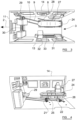
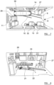
- Figures 3 and 4 show the situation where a stretcher 24 mounted on a wheeled frame with front legs 25 and rear legs 26 is introduced into the rear of the ambulance through the entryway 3. As previously discussed, the stretcher 24 may be wheeled up a ramp to access the entryway 3.
- the stretcher 24 enters the ambulance in a generally longitudinal direction, and its front and rear legs 25, 26 engage with, and lock with respect to, the front and rear locks 21, 22, which are shown in a first position.
- the front and rear locks 21, 22 are positioned towards the rear of the ambulance floor, so the front lock 21 is positioned close to the rear end 19 of the third track 10, and the rear lock 22 is positioned close to the rear ends 16, 17 of the first and second tracks 8, 9.
- the front and rear locks 21, 22 are conveniently positioned to receive the front and rear legs 25, 26.
- the front and rear locks 21, 22 are arranged such that each one is aligned with the normal forward direction of travel 2 of the ambulance, and the front and rear locks 21, 22 are also aligned with one another in a direction which is parallel with the forward direction of travel 2 of the ambulance.
- the stretcher 24 therefore locks in position towards the rear of the ambulance floor, in a way that is aligned with the ambulance.
- a first seat 27 is provided against the right side wall 14, towards the rear of the ambulance.
- the first seat 27 is positioned on the right rear wheel-arch 28, which protrudes into the cabin.
- the first seat 27 has a foldable squab, and may also rotate to point in a convenient direction.
- the first seat 27 is otherwise fixed in place, in this example.
- a second seat 29 is positioned against the front wall 11, and is slideable laterally within the ambulance on a track 30, which is of known type.
- the second seat 29 may slide laterally and be fixed in place in a variety of positions along the front wall 11.
- the second seat 29 also has a foldable squab, and can again be rotated to face in any suitable direction.
- Third and fourth seats 31, 32 are provided against the left side wall 13, and are slideable on a track 33, which extends along a part of this left side wall 13.
- the third and fourth seats 31, 32 each have foldable squabs, and may again rotate facing any suitable direction.
- the first seat 27 has its squab folded into a retracted position. This is, in the example shown, necessary for the stretcher 24 to be moved into the first position, as shown in figures 3 and 4 .
- the front and rear locks 21, 22, along with the stretcher 24 itself, can be moved forwardly with respect to the ambulance, into a second position, which is shown in figures 5 and 6 .
- the front and rear locks 21, 22 have been moved forwardly along the tracks 8, 9, 10, into a position where the stretcher 24 is roughly central within the rear cabin of the ambulance, in the longitudinal direction thereof.
- the first seat 27 still has its squab retracted.
- the second seat 29 has its squab folded down and faces rearwardly. It can be seen that, in this position, the second seat 29 is well placed for an operative to sit near the head of the patient, which will be at the forward end of the stretcher 24.
- the fourth seat 32 also has its squab deployed in this position, and it can be seen that this seat 32 is well positioned for an operative to sit beside a patient who is on the stretcher 24.
- the stretcher 24 can be moved further forwardly into a third position, which is shown in figures 7 and 8 .
- the front lock 21 is moved as far or nearly as far forward as it will go, i.e. to a position near the front ends 18, 20 of the second and third tracks 9, 10.
- the rear lock 22 lies near the front end 16 of the first track 8.
- the stretcher 24 is close to the front wall 11 of the ambulance, and also close to the right side wall 14 thereof.
- the first, third and fourth seats 27, 31, 32 are all rotated so that they face forwardly, and the squabs thereof are deployed. These three seats may be used to accommodate ambulance crew when the ambulance is driving to its destination.
- the second seat 29 is shown in figures 7, 8 with its squab retracted, but this seat 29 may also be occupied by a member of ambulance crew who can sit beside the head of the patient while the vehicle is in transit.
- the stretcher 24 in the first position, has just entered the ambulance, and is conveniently received by the front and rear locks 21, 22.
- the stretcher 24 In the second position, the stretcher 24 is moved into a more central position within the ambulance, and this allows space for several members of the ambulance crew to attend to the patient in an effective manner, which makes good use of the space within the ambulance.
- the stretcher 24 is appropriately positioned for the ambulance to drive to its destination, while still allowing at least one operative to attend to the patient from a convenient position, near the patient's head.
- the stretcher 24 when the stretcher 24 is in the third position and is to be removed from the ambulance, the stretcher 24 is moved rearwardly, into the second position and then the first position, and the front and rear legs 25, 26 of the stretcher 24 can then be disengaged from the front and rear locks 21, 22 (as will be discussed in more detail below), and the stretcher 24 can be removed from the ambulance through the rear entryway 3.
- the stretcher 24 may be rolled down a suitable ramp, lowered down on a motorised hoist or platform, or removed in any other suitable way.
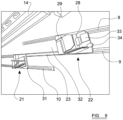
- Figure 9 shows a view of front and rear locks 21, 22, suitable for use with the present invention, without a stretcher attached to them.
- the front and rear locks 21, 22 are shown mounted on tracks 8, 9, 10 on the floor of an ambulance, as discussed above.
- the locks 21, 22 can slide along the length of the tracks 8, 9, 10.
- the tracks 8, 9, 10 each take the form of a straight groove, and are not scalloped or otherwise shaped in a way that would stop or hinder an object sliding along the groove.
- the front and rear locks 21, 22 each include a known floor attachment.
- this includes a known floor attachment 35, for instance as supplied by Stryker ® .
- the standard floor attachment 35 is adapted to be attached to parallel tracks which are aligned with the forward direction of travel of an ambulance, (e.g. in the setup shown in figure 1 ).
- the rear lock 22 further includes a support frame 36, which has fittings on its underside (not shown) which can fit into, slide along, and lock with respect to, the first and second tracks 8, 9.
- the support frame 36 generally comprises a sheet of metal, such as steel, or any other suitable robust material.
- the support frame 36 has a suitable aperture formed therein to receive the standard floor attachment 35, and fix it robustly in place with respect to the support frame 36.
- the standard floor attachment 35 may be removably attached to the support frame 36, for instance through one or more bolts, rivets or pins, or may alternatively be more permanently attached to the support frame 36, for instance by welding.
- the support frame 36 On its underside the support frame 36 has an engagement arrangement (not shown) which is adapted to fit into, and slide along the first and second tracks 8, 9.
- the tracks 8, 9, 10 may each comprise a groove having a pair of inwardly-protruding lips at its entrance, and the engagement arrangement may comprise a pair of spaced-apart, downwardly protruding T-shaped bars, which fit into the grooves and are received under the inwardly protruding lips.
- T-shaped bars which fit into the grooves and are received under the inwardly protruding lips.
- the invention is not limited to this, and any other suitable arrangement of track shape and engagement arrangement may be used.
- the known floor attachment 35 When the known floor attachment 35 is attached to the support frame 36, the known floor attachment 35 is angled with respect to the parts of the support frame 36 that engage with the first and second tracks 8, 9, so that when the support frame 36 is attached to the first tracks 8, 9, the known floor attachment 35 is oriented in a direction which is generally parallel with the normal forward direction of travel of the ambulance.
- this lock 21 includes a known floor attachment 37, supported by a support frame 38, which may take a generally similar form to the support frame 36 of the rear lock 22.
- the support frame 38 has suitable fittings to be engaged with, travel along and be locked with respect to the second and third tracks 9, 10, and the known floor attachment 37 is angled as it is received in the support frame 38, so that it is generally aligned with the forward direction of travel of the ambulance.
- front and rear locks incorporate a known floor attachment
- the front and rear locks may be entirely purpose-built, and include an engagement arrangement to cooperate with the track and a locking arrangement to engage and receive the appropriate legs of a stretcher.
- a spacing arrangement 23 is provided between the front and rear locks 21, 22.
- the spacing arrangement 23 extends between the respective support frames 36, 38.
- the spacing arrangement 23 comprises a rigid bar (not shown) formed from metal or another robust material, which is received in the groove of the second track 9.
- the bar is attached to the front and rear support frames 36, 38, so that the distance between these two support frames 36, 38 remains constant.
- a cover 39 which may be formed from rubber or any other suitable material, covers the bar. This cover 39 helps to prevent dust and other substances from entering the groove of the second track 9 between the front and rear locks 21, 22.
- the front and rear locks 21, 22 may slide along the tracks 8, 9, 10 as one unit, retaining the desired spacing to receive a standard stretcher frame, and also ensuring that the front and rear locks 21, 22 are correctly aligned with one another at all times.
- a locking transmission arrangement extends between the front and rear locks 21, 22.
- This may take the form, for example, of a Bowden cable, although any other suitable transmission arrangement may be used.
- the locking controls are provided on the rear lock 22, as these are more likely to be readily accessible to an operator.
- the stretcher 24 will be moved into the ambulance by an operator who pushes the stretcher from its rear side. The feet of the operator will therefore be in close proximity to the rear lock 22, and pedals can be provided on the rear lock 22 to allow the operator to lock and release the rear lock 22.
- the stretcher 24 is removed from the ambulance, it is likely to be by an operator who pulls the stretcher from its rear end. Once again, the feet of the operator will be in close proximity to the rear lock 22.
- locking holes are formed through the tracks 8, 9, 10, and also optionally into the ambulance floor, to allow the stretcher 24 to be locked at each of the three positions (i.e. the positions shown in figures 3 and 4 , 5 and 6 , and 7 and 8 ).
- locking holes may be provided in more, fewer, or different locations, and the invention is not limited to this.
- the front and rear support frames 36, 38 have locking arrangements including plungers which may protrude downwardly and fit into the locking holes.
- the front and rear locks 21, 22 may be placed in an unlocked mode, in which the plungers are raised above the level of the locking holes. In this mode, the front and rear locks 21, 22 may be slid freely along the tracks 8, 9, 10 to a new position.
- the front and rear locks 21, 22 may also be placed in a locking mode, in which the plungers are biased downwardly towards the ambulance floor, for instance by one or more suitable springs.
- a locking mode in which the plungers are biased downwardly towards the ambulance floor, for instance by one or more suitable springs.
- the front and rear locks 21, 22 may still be slid along the tracks 8, 9, 10, with the plungers sliding along the bottom surfaces of the tracks 8, 9, 10.
- the plungers will be driven into the locking holes by the biasing force, and the front and rear locks 21, 22 will therefore be locked in place with respect to the ambulance floor.
- suitable locking holes and plungers are provided so that, when the plungers of the front lock 21 are aligned with locking holes, the plungers of the rear lock 22 are also simultaneously aligned with locking holes. This will ensure that, as the stretcher reaches one of the positions, the plungers of both the front and rear locks 21, 22 will engage with locking holes at the same moment.
- the Bowden cable is attached to the plungers of the rear lock 22, and passes through the spacing arrangement 23, for instance passing between the bar and the cover 39.
- the Bowden cable extends to the front lock 22, where it is again attached to the plungers thereof.
- An operative may press his/her foot on the locking pedal 33, and place both the front and rear locks 21, 22 in the locking mode simultaneously.
- the operative may press a release pedal 34 with his/her foot, which will simultaneously place both the front and rear locks 21, 22 in the unlocked mode.
- the three tracks slant towards the front right corner of the interior space of the ambulance.
- the direction of slant may be reversed, i.e. so that the tracks slant towards the front left-hand corner of the ambulance floor.
- the direction of slant may be selected as a matter of preference, to fit with other equipment and/or fittings within the ambulance, and the direction of slant may also be influenced by whether the ambulance is a left-hand or right-hand drive vehicle.
- embodiments of the invention provide a method for attaching an object such as the frame of a stretcher to the floor of a vehicle, such as an ambulance, in a manner which is straightforward and easy to operate. Moreover, this will allow a stretcher to be placed in positions on an ambulance floor which are useful for the ambulance crew, and allow efficient and effective use of the space within an ambulance to move and treat a patient.
Landscapes
- Health & Medical Sciences (AREA)
- Public Health (AREA)
- Life Sciences & Earth Sciences (AREA)
- Animal Behavior & Ethology (AREA)
- General Health & Medical Sciences (AREA)
- Veterinary Medicine (AREA)
- Engineering & Computer Science (AREA)
- Transportation (AREA)
- Mechanical Engineering (AREA)
- Invalid Beds And Related Equipment (AREA)
- Seats For Vehicles (AREA)
Description
- This application relates to floor fixings in vehicles, and particularly concerns floor fixings in vehicles such as ambulances. A vehicle comprising such an arrangement is disclosed in the
US4341415 . - Many ambulances (and other similar vehicles) have fixings which are installed in the vehicle floor to allow a patient on a stretcher to be accommodated in a convenient way within the ambulance.
Figure 1 shows a schematic view of the maininternal space 1 of an ambulance, as viewed from directly above. An arrow (indicated by reference numeral 2) designates the normal forward direction of travel of the ambulance, and anentryway 3, which may be accessed through the rear doors (not shown), is also shown. - Four
parallel tracks 4 are installed in thefloor 5 of the ambulance. Eachtrack 4 generally comprises a groove having a scalloped edge. A known floor fitting may be placed into the groove and locked longitudinally in place at a desired position along eachtrack 4. When a suitable fitting is locked in place on eachtrack 4, the fitting may also not be lifted upwardly out of thetrack 4, as will be understood by the skilled reader. -
Figure 1 schematically shows astandard front lock 6, and a standardrear lock 7, each of which are positioned on twoadjacent tracks 4. Eachlock lock parallel tracks 4, and locked in place with respect to thefloor 5 of the ambulance. In the arrangement shown infigure 1 , both thefront lock 6 and therear lock 7 are attached on the same pair ofparallel tracks 4, and the front andrear locks - The
tracks 4 to which thelocks entryway 3, and are located near one side wall, as is common practice. - In use, a stretcher, mounted on a standardised wheeled frame, is introduced into the ambulance through the
entryway 3. The stretcher will generally be wheeled up a suitable ramp or may be lifted up on a motorised hoist or platform. - Once in the ambulance, the stretcher must be moved to one side, and the front and rear wheels of the stretcher's frame can be attached to the front and
rear locks rear locks rear locks rear locks rear lock - The stretcher, along with any patient resting thereon, is then locked in place with respect to the ambulance floor. There may be various seats and other equipment (not shown) arranged around the interior of the ambulance, which can then be used to help personnel to treat or otherwise assist the patient until the ambulance reaches its destination.
- This known setup suffers from certain drawbacks. For instance, the front and
rear locks tracks 4 at exactly the correct longitudinal distance apart, to interact correctly with the frame on which the stretcher is mounted. If thelocks locks - It is also relatively difficult to move the
locks tracks 4, or laterally across theambulance floor 5 onto a different pair oftracks 4. In general, thelocks tracks 4, and lifted out of thetracks 4 to be placed in a new position. Thelocks locks ambulance floor 5 in a swift and reliable manner. - It is an object of the present intention to seek to address some or all of the above drawbacks.
- Accordingly, one aspect of the invention provides a vehicle according to
claim 1. - Preferred features of the invention are set out in the dependent claims.
- In order that the invention may be more readily understood, embodiments thereof will now be described, by way of example, with reference to the accompanying figures, in which:
-
Figure 1 is a schematic view of a known arrangement for an ambulance floor; -
Figure 2 is a schematic view of an arrangement embodying the present invention for an ambulance floor; -
Figures 3 and 4 show a stretcher in a first position, in accordance with the arrangement shown infigure 2 ; -
Figures 5 and 6 show a stretcher in a second position, in accordance with the arrangement shown infigure 2 ; -
Figures 7 and 8 show a stretcher in a third position, in accordance with the arrangement shown infigure 2 ; and -
Figure 9 shows front and rear locks suitable for use with the present invention. -
Figure 2 shows a schematic view of thefloor 5 of an ambulance, according to the present invention. As before, the ambulance has a normal forward direction of travel indicated byreference numeral 2, and has arear entryway 3 which may be accessed through rear doors (not shown). - First, second, and
third tracks floor 5 of the ambulance. These threetracks tracks travel 2 of the ambulance. The angle between eachtrack travel 2 is preferably between 6° and 30°, and is more preferably between 8° and 18°. The inventors have found that the most preferred angle is 14°, or around 14°. - The rear cabin of an ambulance will usually have a generally rectangular shape, having a
front wall 11 and a parallelrear wall 12, and parallel left andright side walls rear walls tracks side walls - A
first track 8 is, in the configuration shown infigure 2 , set closest to aright side wall 14, i.e. the wall which is on the right if the ambulance is viewed from the rear. Thefirst track 8 has arear end 15, which is near theentryway 3, and extends to afront end 16 which is close to theright side wall 14. - A second one 9 of the tracks is spaced apart from the
first track 8, and is closer to theleft side wall 13. Thesecond track 9 extends from arear end 17, which is again close to theentryway 3 and lies generally level with therear end 15 of thefirst track 8, and extends to afront end 18 which is close to theright side wall 14, and also to thefront wall 11. - Finally, the
third track 10 is spaced apart from thesecond track 9 in a direction towards theleft side wall 13. Thethird track 10 extends from arear end 19, which is set further forward than therear end 17 of thesecond track 9, and extends to afront end 20 which lies near to thefront wall 11, generally level with thefront end 18 of thesecond track 9. - The spacing between the first and
second tracks third tracks - A
front lock 21 and arear lock 22 are schematically shown infigure 2 , arranged on thetracks - The
front lock 21 is fitted into the second andthird tracks tracks front lock 21 is, in the arrangement shown infigure 2 , positioned relatively near to thefront ends third tracks - The
rear lock 22 is fitted into the first andsecond tracks rear ends tracks - It will therefore be understood that both the
front lock 21 and therear lock 22 are fitted into thesecond track 9, which is the middle one of the threetracks - It is preferred that, as shown in
figure 2 , the front andrear locks travel 2 of the ambulance. In other words, if the support frame of a conventional stretcher is attached to thelocks travel 2 of the ambulance. - It will therefore be understood that the
locks tracks locks tracks - The front and
rear locks locks travel 2 of the ambulance. - A
spacing arrangement 23 extends between the front andrear locks rear locks - In preferred embodiments of the invention, the
spacing arrangement 23 passes along, or fits into, or is otherwise engaged with, the portion of thesecond track 9 that extends between the front andrear locks rear locks tracks rear locks - Importantly, this spacing is such that, as the front and
rear locks tracks rear locks travel 2 of the ambulance. - The spacing arrangement will be described in more detail below.
-
Figures 3 and 4 show the situation where astretcher 24 mounted on a wheeled frame withfront legs 25 andrear legs 26 is introduced into the rear of the ambulance through theentryway 3. As previously discussed, thestretcher 24 may be wheeled up a ramp to access theentryway 3. - The
stretcher 24 enters the ambulance in a generally longitudinal direction, and its front andrear legs rear locks rear locks front lock 21 is positioned close to therear end 19 of thethird track 10, and therear lock 22 is positioned close to the rear ends 16, 17 of the first andsecond tracks - As can be seen from
figures 3 and 4 , as thestretcher 24 is first introduced into the ambulance through theentryway 3, the front andrear locks rear legs - As discussed above, the front and
rear locks travel 2 of the ambulance, and the front andrear locks travel 2 of the ambulance. Thestretcher 24 therefore locks in position towards the rear of the ambulance floor, in a way that is aligned with the ambulance. - In the arrangement shown, four seats are provided within the rear of the ambulance.
- A
first seat 27 is provided against theright side wall 14, towards the rear of the ambulance. In the example shown, thefirst seat 27 is positioned on the right rear wheel-arch 28, which protrudes into the cabin. Thefirst seat 27 has a foldable squab, and may also rotate to point in a convenient direction. Thefirst seat 27 is otherwise fixed in place, in this example. - A
second seat 29 is positioned against thefront wall 11, and is slideable laterally within the ambulance on atrack 30, which is of known type. Thesecond seat 29 may slide laterally and be fixed in place in a variety of positions along thefront wall 11. Thesecond seat 29 also has a foldable squab, and can again be rotated to face in any suitable direction. - Third and
fourth seats left side wall 13, and are slideable on atrack 33, which extends along a part of thisleft side wall 13. The third andfourth seats - In the configuration shown in
figures 3 and 4 , thefirst seat 27 has its squab folded into a retracted position. This is, in the example shown, necessary for thestretcher 24 to be moved into the first position, as shown infigures 3 and 4 . - Once the
stretcher 24 is in place, the front andrear locks stretcher 24 itself, can be moved forwardly with respect to the ambulance, into a second position, which is shown infigures 5 and 6 . In these figures, the front andrear locks tracks stretcher 24 is roughly central within the rear cabin of the ambulance, in the longitudinal direction thereof. - In this position, the
first seat 27 still has its squab retracted. However, thesecond seat 29 has its squab folded down and faces rearwardly. It can be seen that, in this position, thesecond seat 29 is well placed for an operative to sit near the head of the patient, which will be at the forward end of thestretcher 24. - The
fourth seat 32 also has its squab deployed in this position, and it can be seen that thisseat 32 is well positioned for an operative to sit beside a patient who is on thestretcher 24. - From this position, the
stretcher 24 can be moved further forwardly into a third position, which is shown infigures 7 and 8 . In this position, thefront lock 21 is moved as far or nearly as far forward as it will go, i.e. to a position near the front ends 18, 20 of the second andthird tracks rear lock 22 lies near thefront end 16 of thefirst track 8. Thestretcher 24 is close to thefront wall 11 of the ambulance, and also close to theright side wall 14 thereof. - In this position, the first, third and
fourth seats - The
second seat 29 is shown infigures 7, 8 with its squab retracted, but thisseat 29 may also be occupied by a member of ambulance crew who can sit beside the head of the patient while the vehicle is in transit. - In the configuration shown in
figures 7 and 8 , thesecond seat 29 has been moved along thetrack 30 on which it is supported, away from theright side wall 14, to allow thestretcher 24 to move all the way to the front of thetracks - In summary, in the first position, the
stretcher 24 has just entered the ambulance, and is conveniently received by the front andrear locks - In the second position, the
stretcher 24 is moved into a more central position within the ambulance, and this allows space for several members of the ambulance crew to attend to the patient in an effective manner, which makes good use of the space within the ambulance. - Finally, in the third position, the
stretcher 24 is appropriately positioned for the ambulance to drive to its destination, while still allowing at least one operative to attend to the patient from a convenient position, near the patient's head. - It will also be noted that the arrangement of the
tracks right wheel arch 28, into the third position, which is well-suited for the ambulance to be driven. In a conventional arrangement, such as shown infigure 1 , this would be very difficult to achieve. Any track which is spaced far enough from the wall of the ambulance to avoid the wheel arch will only allow the stretcher to move to a forward position which is still spaced apart by a significant distance from the side wall. - As the skilled reader will understand, when the
stretcher 24 is in the third position and is to be removed from the ambulance, thestretcher 24 is moved rearwardly, into the second position and then the first position, and the front andrear legs stretcher 24 can then be disengaged from the front andrear locks 21, 22 (as will be discussed in more detail below), and thestretcher 24 can be removed from the ambulance through therear entryway 3. As discussed above, thestretcher 24 may be rolled down a suitable ramp, lowered down on a motorised hoist or platform, or removed in any other suitable way. -
Figure 9 shows a view of front andrear locks rear locks tracks - As will be understood from the description above, it is preferred that the
locks tracks tracks - In this example, the front and
rear locks rear lock 22 in more detail, this includes a known floor attachment 35, for instance as supplied by Stryker®. The standard floor attachment 35 is adapted to be attached to parallel tracks which are aligned with the forward direction of travel of an ambulance, (e.g. in the setup shown infigure 1 ). - The
rear lock 22 further includes a support frame 36, which has fittings on its underside (not shown) which can fit into, slide along, and lock with respect to, the first andsecond tracks - The support frame 36 generally comprises a sheet of metal, such as steel, or any other suitable robust material. The support frame 36 has a suitable aperture formed therein to receive the standard floor attachment 35, and fix it robustly in place with respect to the support frame 36. The standard floor attachment 35 may be removably attached to the support frame 36, for instance through one or more bolts, rivets or pins, or may alternatively be more permanently attached to the support frame 36, for instance by welding.
- On its underside the support frame 36 has an engagement arrangement (not shown) which is adapted to fit into, and slide along the first and
second tracks tracks tracks - The invention is not limited to this, and any other suitable arrangement of track shape and engagement arrangement may be used.
- When the known floor attachment 35 is attached to the support frame 36, the known floor attachment 35 is angled with respect to the parts of the support frame 36 that engage with the first and
second tracks first tracks - Turning to the
front lock 21, once again thislock 21 includes a known floor attachment 37, supported by a support frame 38, which may take a generally similar form to the support frame 36 of therear lock 22. Once again, the support frame 38 has suitable fittings to be engaged with, travel along and be locked with respect to the second andthird tracks - While in this example the front and rear locks incorporate a known floor attachment, in other embodiments the front and rear locks may be entirely purpose-built, and include an engagement arrangement to cooperate with the track and a locking arrangement to engage and receive the appropriate legs of a stretcher.
- A
spacing arrangement 23 is provided between the front andrear locks spacing arrangement 23 extends between the respective support frames 36, 38. - In one embodiment, the
spacing arrangement 23 comprises a rigid bar (not shown) formed from metal or another robust material, which is received in the groove of thesecond track 9. The bar is attached to the front and rear support frames 36, 38, so that the distance between these two support frames 36, 38 remains constant. - In the example shown, a cover 39, which may be formed from rubber or any other suitable material, covers the bar. This cover 39 helps to prevent dust and other substances from entering the groove of the
second track 9 between the front andrear locks - The skilled reader will understand that, because of the
spacing arrangement 23, the front andrear locks tracks rear locks - In preferred embodiments of the invention, a locking transmission arrangement extends between the front and
rear locks - This may ensure that the front and rear locks, 21, 22 may be locked with respect to the ambulance floor by operating a single control, which can be positioned on only one of the
locks rear lock 22, as these are more likely to be readily accessible to an operator. In general, thestretcher 24 will be moved into the ambulance by an operator who pushes the stretcher from its rear side. The feet of the operator will therefore be in close proximity to therear lock 22, and pedals can be provided on therear lock 22 to allow the operator to lock and release therear lock 22. Similarly, when thestretcher 24 is removed from the ambulance, it is likely to be by an operator who pulls the stretcher from its rear end. Once again, the feet of the operator will be in close proximity to therear lock 22. - In one preferred embodiment, locking holes (not shown) are formed through the
tracks stretcher 24 to be locked at each of the three positions (i.e. the positions shown infigures 3 and 4 ,5 and6 , and7 and 8 ). In other embodiments, locking holes may be provided in more, fewer, or different locations, and the invention is not limited to this. - The front and rear support frames 36, 38 have locking arrangements including plungers which may protrude downwardly and fit into the locking holes.
- The front and
rear locks rear locks tracks - The front and
rear locks rear locks rear locks tracks tracks rear locks - In preferred embodiments, suitable locking holes and plungers are provided so that, when the plungers of the
front lock 21 are aligned with locking holes, the plungers of therear lock 22 are also simultaneously aligned with locking holes. This will ensure that, as the stretcher reaches one of the positions, the plungers of both the front andrear locks - This may be achieved by providing, for instance, a Bowden cable which is connected to a locking
pedal 33, which is provided on the support frame 36 of therear lock 22. The Bowden cable is attached to the plungers of therear lock 22, and passes through thespacing arrangement 23, for instance passing between the bar and the cover 39. The Bowden cable extends to thefront lock 22, where it is again attached to the plungers thereof. An operative may press his/her foot on the lockingpedal 33, and place both the front andrear locks release pedal 34 with his/her foot, which will simultaneously place both the front andrear locks - The skilled reader will understand how this arrangement will make it very straightforward for an operative to move the
stretcher 24 between the various desired positions, locking the stretcher in place with respect to the ambulance floor where needed, and easily unlocking the stretcher to be moved to a different position, or removed from the ambulance entirely. - In the example discussed above, the three tracks slant towards the front right corner of the interior space of the ambulance. However, in other embodiments the direction of slant may be reversed, i.e. so that the tracks slant towards the front left-hand corner of the ambulance floor. The direction of slant may be selected as a matter of preference, to fit with other equipment and/or fittings within the ambulance, and the direction of slant may also be influenced by whether the ambulance is a left-hand or right-hand drive vehicle.
- It will be understood that embodiments of the invention provide a method for attaching an object such as the frame of a stretcher to the floor of a vehicle, such as an ambulance, in a manner which is straightforward and easy to operate. Moreover, this will allow a stretcher to be placed in positions on an ambulance floor which are useful for the ambulance crew, and allow efficient and effective use of the space within an ambulance to move and treat a patient.
- When used in this specification and claims, the terms "comprises" and "comprising" and variations thereof mean that the specified features, steps or integers are included. The terms are not to be interpreted to exclude the presence of other features, steps or components.
Claims (15)
- A vehicle comprising an arrangement for selectively attaching an object (24) to the floor (5) of the vehicle, the arrangement comprising:first, second and third elongate tracks (8, 9, 10) provided on, or formed as part of, the vehicle floor (5), wherein the vehicle has a normal forward direction of travel, and the tracks (8, 9, 10) are inclined at an angle with respect to this normal forward direction of travel; anda first locking arrangement (22), which has an engagement arrangement adapted to be received in, and travel along, the first and second tracks (8, 9), and a second locking arrangement (21), which has an engagement arrangement adapted to be received in, and travel along, the second and third tracks (9, 10), each of the locking arrangements (22, 21) being able to receive and removably retain a part of the object (24).
- A vehicle according to claim 1, wherein a spacing arrangement (23) is provided between the first and second locking arrangements (22, 21), to maintain a fixed distance between the first and second locking arrangements (22, 21) as the first and second locking arrangements (22, 21) travel along the tracks (8, 9, 10).
- A vehicle according to claim 2, wherein the spacing arrangement (23) is received in the second track (9), in which the first and second locking arrangements (22, 21) are both received.
- A vehicle according to claim 3, wherein the engagement arrangements of the first and second locking arrangements (22, 21) are each received in at least one track (8, 10) in which the other the engagement arrangement of the first and second locking arrangements (22, 21) is not also received.
- A vehicle according to claim 3 or 4, wherein, when the engagement arrangements of the first and second locking arrangements (22, 21) are received in the tracks (8, 9, 10), the first and second locking arrangements (22, 21) are substantially aligned with one another in a direction parallel with the normal forward direction of travel.
- A vehicle according to any preceding claim, wherein each of the locking arrangements (22, 21) may be placed in a locked position, in which the locking arrangement is fixed in position with respect to at least one of the tracks (8, 9, 10), and an unlocked configuration, in which the locking arrangement (22, 21) may slide along the length of at least one of the tracks (8, 9, 10).
- A vehicle according to claim 6, wherein each of the locking arrangements (22, 21) may be fixed in position with respect to at least one of the tracks (8, 9, 10) at a plurality of positions along the length of the track (8, 9, 10).
- A vehicle according to claim 6 or 7 further comprising a locking control (33) which is operable to place both the first and second locking arrangements (22, 21) in the locked position.
- A vehicle according to claim 8, in which a locking transmission arrangement extends between the first and second locking arrangements (22, 21), and preferably, when dependent upon claim 2, wherein the locking transmission arrangement extends along, or adjacent to, the spacing arrangement (23).
- A vehicle according to any one of claims 6 to 9, further comprising an unlocking control (34), which may be operated to place both the first and second locking arrangements (22, 21) in the unlocked position.
- A vehicle according to any preceding claim, positioned within an internal space of a vehicle, and preferably wherein the vehicle has a rear entryway (3), and one or more of the elongate tracks (8, 9, 10) terminate at one of its ends near the entryway (3).
- A vehicle according to claim 11, wherein the front end of at least one of the tracks (8, 9, 10) terminates near a side wall (14) of the vehicle.
- A vehicle according to claims 11 to 12, wherein the vehicle is an ambulance, and the object (24) is a frame of a stretcher.
- A vehicle according to any one of claims 11 to 13, further comprising a seat (29) which is slidably mounted within the internal space of the vehicle, and wherein the seat (29) may slide from a first position, which is relatively close to a position of one of the locking arrangements (21), to a second position, which is further from the position of the one of the locking arrangements (21).
- A vehicle according to claim 14, when dependent upon claim 13, wherein when a stretcher is attached to the first and second locking arrangements (22, 21), and the first and second locking arrangements (22, 21) are moved to a position with respect to the tracks (8, 9, 10), the seat (29) would obstruct the movement of the stretcher in the first position, but would not obstruct the movement of the stretcher in the second position.
Applications Claiming Priority (2)
| Application Number | Priority Date | Filing Date | Title |
|---|---|---|---|
| GB1801841.6A GB2570712B (en) | 2018-02-05 | 2018-02-05 | Improvements in or relating to floor fixings in vehicles |
| PCT/GB2019/050290 WO2019150131A1 (en) | 2018-02-05 | 2019-02-04 | Improvements in or relating to floor fixings in vehicles |
Publications (2)
| Publication Number | Publication Date |
|---|---|
| EP3749273A1 EP3749273A1 (en) | 2020-12-16 |
| EP3749273B1 true EP3749273B1 (en) | 2024-09-04 |
Family
ID=61730865
Family Applications (1)
| Application Number | Title | Priority Date | Filing Date |
|---|---|---|---|
| EP19704429.0A Active EP3749273B1 (en) | 2018-02-05 | 2019-02-04 | Improvements in or relating to floor fixings in vehicles |
Country Status (3)
| Country | Link |
|---|---|
| EP (1) | EP3749273B1 (en) |
| GB (1) | GB2570712B (en) |
| WO (1) | WO2019150131A1 (en) |
Families Citing this family (6)
| Publication number | Priority date | Publication date | Assignee | Title |
|---|---|---|---|---|
| JP7555098B2 (en) * | 2020-07-13 | 2024-09-24 | 株式会社赤尾 | Anti-vibration stand for ambulances |
| US12077068B2 (en) | 2020-11-09 | 2024-09-03 | Ford Global Technologies, Llc | Authorization-based adjustment of passenger compartment arrangement |
| US11904732B2 (en) | 2020-11-09 | 2024-02-20 | Ford Global Technologies, Llc | Vehicular system capable of adjusting a passenger compartment from a first arrangement to a child care arrangement |
| US11772517B2 (en) | 2020-11-09 | 2023-10-03 | Ford Global Technologies, Llc | Vehicular system capable of adjusting a passenger compartment from a child seat arrangement to a second arrangement |
| US12257932B2 (en) | 2020-11-09 | 2025-03-25 | Ford Global Technologies, Llc | Exterior imager utilized in adjusting a passenger compartment arrangement |
| WO2023107424A2 (en) * | 2021-12-06 | 2023-06-15 | Peter Walker | Mobile package transfer rack |
Family Cites Families (8)
| Publication number | Priority date | Publication date | Assignee | Title |
|---|---|---|---|---|
| DE7838370U1 (en) * | 1978-12-23 | 1979-04-19 | Westfalia-Werke Franz Knoebel & Soehne Kg, 4840 Rheda-Wiedenbrueck | VEHICLE, MINIBU, O.DGL. WITH AT LEAST TWO ROWS OF SEATS |
| US6695561B2 (en) * | 2000-02-09 | 2004-02-24 | Leonard D. Barry | Container drive-by-transfer and system |
| JP2001347858A (en) * | 2000-06-08 | 2001-12-18 | Kasai Kogyo Co Ltd | Seat system for vehicle |
| US7014410B2 (en) * | 2002-04-01 | 2006-03-21 | Barry Leonard D | Container drive-by transfer and system |
| US20080290706A1 (en) * | 2007-05-25 | 2008-11-27 | Aisin Seiki Kabushiki Kaisha | Seat position adjusting apparatus for vehicle |
| JP4582424B2 (en) * | 2007-07-11 | 2010-11-17 | 関東自動車工業株式会社 | Wheelchair storage structure |
| JP5228635B2 (en) * | 2008-06-09 | 2013-07-03 | トヨタ紡織株式会社 | vehicle |
| GB2467524A (en) * | 2009-01-30 | 2010-08-04 | Roderick Lynch | A convertible transportation apparatus for receiving a stretcher |
-
2018
- 2018-02-05 GB GB1801841.6A patent/GB2570712B/en active Active
-
2019
- 2019-02-04 EP EP19704429.0A patent/EP3749273B1/en active Active
- 2019-02-04 WO PCT/GB2019/050290 patent/WO2019150131A1/en not_active Ceased
Also Published As
| Publication number | Publication date |
|---|---|
| GB2570712A (en) | 2019-08-07 |
| EP3749273A1 (en) | 2020-12-16 |
| GB201801841D0 (en) | 2018-03-21 |
| WO2019150131A1 (en) | 2019-08-08 |
| GB2570712B (en) | 2022-07-27 |
Similar Documents
| Publication | Publication Date | Title |
|---|---|---|
| EP3749273B1 (en) | Improvements in or relating to floor fixings in vehicles | |
| CA2098444C (en) | Patient transport system | |
| US8956102B2 (en) | Vehicle with wheelchair positioning mechanism | |
| US5524952A (en) | Semi-ambulatory companion seating system and method | |
| US7621580B2 (en) | Ambulance seating system | |
| US6923606B2 (en) | Medical evacuation patient support pallet | |
| EP0583406B1 (en) | Automatically adaptable fastening system for wheeled cots and similar devices | |
| US9403448B1 (en) | Transfer seat base with pedal guard assembly | |
| DE602005005920T2 (en) | Fastening device for wheelchair | |
| US5884563A (en) | Ride attraction system for the physically disabled | |
| EP1767394B1 (en) | A seating arrangement | |
| EP2504235A2 (en) | Aircraft seat assembly for aircraft passengers having restricted mobility | |
| DE29916236U1 (en) | Mobile device for disabled people | |
| US8413588B2 (en) | Railway service vehicle having wheelchair restraint | |
| EP1717098B1 (en) | Passenger seat for public transportation vehicle | |
| DE2325425A1 (en) | TRANSPORT FOR THE PHYSICALLY DISABLED | |
| EP0148596A1 (en) | Road vehicles | |
| DE202018003604U1 (en) | Retaining device for a wheelchair, in particular for a caregiver wheelchair, in a vehicle | |
| GB2420323A (en) | Securing stretcher in rear of ambulance | |
| EP0780335B1 (en) | Transporting device for persons or loads in a multiple decks aircraft | |
| DE102017205080A1 (en) | Motor vehicle with a mobile vehicle seat and a mobile vehicle seat | |
| DE3541001C1 (en) | Device for the transportation of people | |
| CA2748652C (en) | Railway service vehicle having wheelchair restraint | |
| NL1039036C2 (en) | Floor plate or floor for multifunctional vehicles. | |
| WO2009045214A1 (en) | Ambulance seating system |
Legal Events
| Date | Code | Title | Description |
|---|---|---|---|
| STAA | Information on the status of an ep patent application or granted ep patent |
Free format text: STATUS: UNKNOWN |
|
| STAA | Information on the status of an ep patent application or granted ep patent |
Free format text: STATUS: THE INTERNATIONAL PUBLICATION HAS BEEN MADE |
|
| PUAI | Public reference made under article 153(3) epc to a published international application that has entered the european phase |
Free format text: ORIGINAL CODE: 0009012 |
|
| STAA | Information on the status of an ep patent application or granted ep patent |
Free format text: STATUS: REQUEST FOR EXAMINATION WAS MADE |
|
| 17P | Request for examination filed |
Effective date: 20200805 |
|
| AK | Designated contracting states |
Kind code of ref document: A1 Designated state(s): AL AT BE BG CH CY CZ DE DK EE ES FI FR GB GR HR HU IE IS IT LI LT LU LV MC MK MT NL NO PL PT RO RS SE SI SK SM TR |
|
| AX | Request for extension of the european patent |
Extension state: BA ME |
|
| DAV | Request for validation of the european patent (deleted) | ||
| DAX | Request for extension of the european patent (deleted) | ||
| STAA | Information on the status of an ep patent application or granted ep patent |
Free format text: STATUS: EXAMINATION IS IN PROGRESS |
|
| 17Q | First examination report despatched |
Effective date: 20230802 |
|
| GRAP | Despatch of communication of intention to grant a patent |
Free format text: ORIGINAL CODE: EPIDOSNIGR1 |
|
| STAA | Information on the status of an ep patent application or granted ep patent |
Free format text: STATUS: GRANT OF PATENT IS INTENDED |
|
| INTG | Intention to grant announced |
Effective date: 20231117 |
|
| GRAS | Grant fee paid |
Free format text: ORIGINAL CODE: EPIDOSNIGR3 |
|
| GRAA | (expected) grant |
Free format text: ORIGINAL CODE: 0009210 |
|
| STAA | Information on the status of an ep patent application or granted ep patent |
Free format text: STATUS: THE PATENT HAS BEEN GRANTED |
|
| AK | Designated contracting states |
Kind code of ref document: B1 Designated state(s): AL AT BE BG CH CY CZ DE DK EE ES FI FR GB GR HR HU IE IS IT LI LT LU LV MC MK MT NL NO PL PT RO RS SE SI SK SM TR |
|
| REG | Reference to a national code |
Ref country code: GB Ref legal event code: FG4D |
|
| REG | Reference to a national code |
Ref country code: CH Ref legal event code: EP |
|
| REG | Reference to a national code |
Ref country code: IE Ref legal event code: FG4D |
|
| REG | Reference to a national code |
Ref country code: DE Ref legal event code: R096 Ref document number: 602019058242 Country of ref document: DE |
|
| REG | Reference to a national code |
Ref country code: LT Ref legal event code: MG9D |
|
| REG | Reference to a national code |
Ref country code: NL Ref legal event code: MP Effective date: 20240904 |
|
| PG25 | Lapsed in a contracting state [announced via postgrant information from national office to epo] |
Ref country code: NO Free format text: LAPSE BECAUSE OF FAILURE TO SUBMIT A TRANSLATION OF THE DESCRIPTION OR TO PAY THE FEE WITHIN THE PRESCRIBED TIME-LIMIT Effective date: 20241204 |
|
| PG25 | Lapsed in a contracting state [announced via postgrant information from national office to epo] |
Ref country code: GR Free format text: LAPSE BECAUSE OF FAILURE TO SUBMIT A TRANSLATION OF THE DESCRIPTION OR TO PAY THE FEE WITHIN THE PRESCRIBED TIME-LIMIT Effective date: 20241205 Ref country code: FI Free format text: LAPSE BECAUSE OF FAILURE TO SUBMIT A TRANSLATION OF THE DESCRIPTION OR TO PAY THE FEE WITHIN THE PRESCRIBED TIME-LIMIT Effective date: 20240904 Ref country code: PL Free format text: LAPSE BECAUSE OF FAILURE TO SUBMIT A TRANSLATION OF THE DESCRIPTION OR TO PAY THE FEE WITHIN THE PRESCRIBED TIME-LIMIT Effective date: 20240904 |
|
| PG25 | Lapsed in a contracting state [announced via postgrant information from national office to epo] |
Ref country code: BG Free format text: LAPSE BECAUSE OF FAILURE TO SUBMIT A TRANSLATION OF THE DESCRIPTION OR TO PAY THE FEE WITHIN THE PRESCRIBED TIME-LIMIT Effective date: 20240904 |
|
| PG25 | Lapsed in a contracting state [announced via postgrant information from national office to epo] |
Ref country code: LV Free format text: LAPSE BECAUSE OF FAILURE TO SUBMIT A TRANSLATION OF THE DESCRIPTION OR TO PAY THE FEE WITHIN THE PRESCRIBED TIME-LIMIT Effective date: 20240904 |
|
| PG25 | Lapsed in a contracting state [announced via postgrant information from national office to epo] |
Ref country code: HR Free format text: LAPSE BECAUSE OF FAILURE TO SUBMIT A TRANSLATION OF THE DESCRIPTION OR TO PAY THE FEE WITHIN THE PRESCRIBED TIME-LIMIT Effective date: 20240904 |
|
| PG25 | Lapsed in a contracting state [announced via postgrant information from national office to epo] |
Ref country code: ES Free format text: LAPSE BECAUSE OF FAILURE TO SUBMIT A TRANSLATION OF THE DESCRIPTION OR TO PAY THE FEE WITHIN THE PRESCRIBED TIME-LIMIT Effective date: 20240904 Ref country code: RS Free format text: LAPSE BECAUSE OF FAILURE TO SUBMIT A TRANSLATION OF THE DESCRIPTION OR TO PAY THE FEE WITHIN THE PRESCRIBED TIME-LIMIT Effective date: 20241204 |
|
| PG25 | Lapsed in a contracting state [announced via postgrant information from national office to epo] |
Ref country code: RS Free format text: LAPSE BECAUSE OF FAILURE TO SUBMIT A TRANSLATION OF THE DESCRIPTION OR TO PAY THE FEE WITHIN THE PRESCRIBED TIME-LIMIT Effective date: 20241204 Ref country code: PL Free format text: LAPSE BECAUSE OF FAILURE TO SUBMIT A TRANSLATION OF THE DESCRIPTION OR TO PAY THE FEE WITHIN THE PRESCRIBED TIME-LIMIT Effective date: 20240904 Ref country code: NO Free format text: LAPSE BECAUSE OF FAILURE TO SUBMIT A TRANSLATION OF THE DESCRIPTION OR TO PAY THE FEE WITHIN THE PRESCRIBED TIME-LIMIT Effective date: 20241204 Ref country code: LV Free format text: LAPSE BECAUSE OF FAILURE TO SUBMIT A TRANSLATION OF THE DESCRIPTION OR TO PAY THE FEE WITHIN THE PRESCRIBED TIME-LIMIT Effective date: 20240904 Ref country code: HR Free format text: LAPSE BECAUSE OF FAILURE TO SUBMIT A TRANSLATION OF THE DESCRIPTION OR TO PAY THE FEE WITHIN THE PRESCRIBED TIME-LIMIT Effective date: 20240904 Ref country code: GR Free format text: LAPSE BECAUSE OF FAILURE TO SUBMIT A TRANSLATION OF THE DESCRIPTION OR TO PAY THE FEE WITHIN THE PRESCRIBED TIME-LIMIT Effective date: 20241205 Ref country code: FI Free format text: LAPSE BECAUSE OF FAILURE TO SUBMIT A TRANSLATION OF THE DESCRIPTION OR TO PAY THE FEE WITHIN THE PRESCRIBED TIME-LIMIT Effective date: 20240904 Ref country code: ES Free format text: LAPSE BECAUSE OF FAILURE TO SUBMIT A TRANSLATION OF THE DESCRIPTION OR TO PAY THE FEE WITHIN THE PRESCRIBED TIME-LIMIT Effective date: 20240904 Ref country code: BG Free format text: LAPSE BECAUSE OF FAILURE TO SUBMIT A TRANSLATION OF THE DESCRIPTION OR TO PAY THE FEE WITHIN THE PRESCRIBED TIME-LIMIT Effective date: 20240904 |
|
| REG | Reference to a national code |
Ref country code: AT Ref legal event code: MK05 Ref document number: 1719627 Country of ref document: AT Kind code of ref document: T Effective date: 20240904 |
|
| PG25 | Lapsed in a contracting state [announced via postgrant information from national office to epo] |
Ref country code: NL Free format text: LAPSE BECAUSE OF FAILURE TO SUBMIT A TRANSLATION OF THE DESCRIPTION OR TO PAY THE FEE WITHIN THE PRESCRIBED TIME-LIMIT Effective date: 20240904 |
|
| PG25 | Lapsed in a contracting state [announced via postgrant information from national office to epo] |
Ref country code: PT Free format text: LAPSE BECAUSE OF FAILURE TO SUBMIT A TRANSLATION OF THE DESCRIPTION OR TO PAY THE FEE WITHIN THE PRESCRIBED TIME-LIMIT Effective date: 20250106 Ref country code: IS Free format text: LAPSE BECAUSE OF FAILURE TO SUBMIT A TRANSLATION OF THE DESCRIPTION OR TO PAY THE FEE WITHIN THE PRESCRIBED TIME-LIMIT Effective date: 20250104 |
|
| PG25 | Lapsed in a contracting state [announced via postgrant information from national office to epo] |
Ref country code: SM Free format text: LAPSE BECAUSE OF FAILURE TO SUBMIT A TRANSLATION OF THE DESCRIPTION OR TO PAY THE FEE WITHIN THE PRESCRIBED TIME-LIMIT Effective date: 20240904 Ref country code: RO Free format text: LAPSE BECAUSE OF FAILURE TO SUBMIT A TRANSLATION OF THE DESCRIPTION OR TO PAY THE FEE WITHIN THE PRESCRIBED TIME-LIMIT Effective date: 20240904 |
|
| PG25 | Lapsed in a contracting state [announced via postgrant information from national office to epo] |
Ref country code: EE Free format text: LAPSE BECAUSE OF FAILURE TO SUBMIT A TRANSLATION OF THE DESCRIPTION OR TO PAY THE FEE WITHIN THE PRESCRIBED TIME-LIMIT Effective date: 20240904 Ref country code: AT Free format text: LAPSE BECAUSE OF FAILURE TO SUBMIT A TRANSLATION OF THE DESCRIPTION OR TO PAY THE FEE WITHIN THE PRESCRIBED TIME-LIMIT Effective date: 20240904 |
|
| PG25 | Lapsed in a contracting state [announced via postgrant information from national office to epo] |
Ref country code: CZ Free format text: LAPSE BECAUSE OF FAILURE TO SUBMIT A TRANSLATION OF THE DESCRIPTION OR TO PAY THE FEE WITHIN THE PRESCRIBED TIME-LIMIT Effective date: 20240904 |
|
| PG25 | Lapsed in a contracting state [announced via postgrant information from national office to epo] |
Ref country code: SK Free format text: LAPSE BECAUSE OF FAILURE TO SUBMIT A TRANSLATION OF THE DESCRIPTION OR TO PAY THE FEE WITHIN THE PRESCRIBED TIME-LIMIT Effective date: 20240904 Ref country code: IT Free format text: LAPSE BECAUSE OF FAILURE TO SUBMIT A TRANSLATION OF THE DESCRIPTION OR TO PAY THE FEE WITHIN THE PRESCRIBED TIME-LIMIT Effective date: 20240904 |
|
| REG | Reference to a national code |
Ref country code: DE Ref legal event code: R097 Ref document number: 602019058242 Country of ref document: DE |
|
| PG25 | Lapsed in a contracting state [announced via postgrant information from national office to epo] |
Ref country code: DK Free format text: LAPSE BECAUSE OF FAILURE TO SUBMIT A TRANSLATION OF THE DESCRIPTION OR TO PAY THE FEE WITHIN THE PRESCRIBED TIME-LIMIT Effective date: 20240904 |
|
| PLBE | No opposition filed within time limit |
Free format text: ORIGINAL CODE: 0009261 |
|
| STAA | Information on the status of an ep patent application or granted ep patent |
Free format text: STATUS: NO OPPOSITION FILED WITHIN TIME LIMIT |
|
| 26N | No opposition filed |
Effective date: 20250605 |
|
| REG | Reference to a national code |
Ref country code: DE Ref legal event code: R119 Ref document number: 602019058242 Country of ref document: DE |
|
| PG25 | Lapsed in a contracting state [announced via postgrant information from national office to epo] |
Ref country code: SE Free format text: LAPSE BECAUSE OF FAILURE TO SUBMIT A TRANSLATION OF THE DESCRIPTION OR TO PAY THE FEE WITHIN THE PRESCRIBED TIME-LIMIT Effective date: 20240904 |
|
| PG25 | Lapsed in a contracting state [announced via postgrant information from national office to epo] |
Ref country code: MC Free format text: LAPSE BECAUSE OF FAILURE TO SUBMIT A TRANSLATION OF THE DESCRIPTION OR TO PAY THE FEE WITHIN THE PRESCRIBED TIME-LIMIT Effective date: 20240904 |
|
| REG | Reference to a national code |
Ref country code: CH Ref legal event code: PL |
|
| PG25 | Lapsed in a contracting state [announced via postgrant information from national office to epo] |
Ref country code: LU Free format text: LAPSE BECAUSE OF NON-PAYMENT OF DUE FEES Effective date: 20250204 |
|
| PG25 | Lapsed in a contracting state [announced via postgrant information from national office to epo] |
Ref country code: CH Free format text: LAPSE BECAUSE OF NON-PAYMENT OF DUE FEES Effective date: 20250228 |
|
| REG | Reference to a national code |
Ref country code: BE Ref legal event code: MM Effective date: 20250228 |
|
| PG25 | Lapsed in a contracting state [announced via postgrant information from national office to epo] |
Ref country code: DE Free format text: LAPSE BECAUSE OF NON-PAYMENT OF DUE FEES Effective date: 20250902 |
|
| PG25 | Lapsed in a contracting state [announced via postgrant information from national office to epo] |
Ref country code: FR Free format text: LAPSE BECAUSE OF NON-PAYMENT OF DUE FEES Effective date: 20250228 |
|
| PG25 | Lapsed in a contracting state [announced via postgrant information from national office to epo] |
Ref country code: BE Free format text: LAPSE BECAUSE OF NON-PAYMENT OF DUE FEES Effective date: 20250228 |
|
| PG25 | Lapsed in a contracting state [announced via postgrant information from national office to epo] |
Ref country code: IE Free format text: LAPSE BECAUSE OF NON-PAYMENT OF DUE FEES Effective date: 20250204 |
|
| PGFP | Annual fee paid to national office [announced via postgrant information from national office to epo] |
Ref country code: GB Payment date: 20260303 Year of fee payment: 8 |