EP3749235B1 - Fixation systems for treating charcot foot and other conditions - Google Patents
Fixation systems for treating charcot foot and other conditions Download PDFInfo
- Publication number
- EP3749235B1 EP3749235B1 EP19746853.1A EP19746853A EP3749235B1 EP 3749235 B1 EP3749235 B1 EP 3749235B1 EP 19746853 A EP19746853 A EP 19746853A EP 3749235 B1 EP3749235 B1 EP 3749235B1
- Authority
- EP
- European Patent Office
- Prior art keywords
- plate
- rod
- shaft
- bone
- fixation system
- Prior art date
- Legal status (The legal status is an assumption and is not a legal conclusion. Google has not performed a legal analysis and makes no representation as to the accuracy of the status listed.)
- Active
Links
Images





Classifications
-
- A—HUMAN NECESSITIES
- A61—MEDICAL OR VETERINARY SCIENCE; HYGIENE
- A61B—DIAGNOSIS; SURGERY; IDENTIFICATION
- A61B17/00—Surgical instruments, devices or methods
- A61B17/56—Surgical instruments or methods for treatment of bones or joints; Devices specially adapted therefor
- A61B17/58—Surgical instruments or methods for treatment of bones or joints; Devices specially adapted therefor for osteosynthesis, e.g. bone plates, screws or setting implements
- A61B17/60—Surgical instruments or methods for treatment of bones or joints; Devices specially adapted therefor for osteosynthesis, e.g. bone plates, screws or setting implements for external osteosynthesis, e.g. distractors, contractors
- A61B17/64—Devices extending alongside the bones to be positioned
- A61B17/645—Devices extending alongside the bones to be positioned comprising a framework
-
- A—HUMAN NECESSITIES
- A61—MEDICAL OR VETERINARY SCIENCE; HYGIENE
- A61B—DIAGNOSIS; SURGERY; IDENTIFICATION
- A61B17/00—Surgical instruments, devices or methods
- A61B17/56—Surgical instruments or methods for treatment of bones or joints; Devices specially adapted therefor
- A61B17/58—Surgical instruments or methods for treatment of bones or joints; Devices specially adapted therefor for osteosynthesis, e.g. bone plates, screws or setting implements
- A61B17/60—Surgical instruments or methods for treatment of bones or joints; Devices specially adapted therefor for osteosynthesis, e.g. bone plates, screws or setting implements for external osteosynthesis, e.g. distractors, contractors
- A61B17/62—Ring frames, i.e. devices extending around the bones to be positioned
-
- A—HUMAN NECESSITIES
- A61—MEDICAL OR VETERINARY SCIENCE; HYGIENE
- A61B—DIAGNOSIS; SURGERY; IDENTIFICATION
- A61B17/00—Surgical instruments, devices or methods
- A61B17/56—Surgical instruments or methods for treatment of bones or joints; Devices specially adapted therefor
- A61B17/58—Surgical instruments or methods for treatment of bones or joints; Devices specially adapted therefor for osteosynthesis, e.g. bone plates, screws or setting implements
- A61B17/60—Surgical instruments or methods for treatment of bones or joints; Devices specially adapted therefor for osteosynthesis, e.g. bone plates, screws or setting implements for external osteosynthesis, e.g. distractors, contractors
- A61B17/64—Devices extending alongside the bones to be positioned
- A61B17/6425—Devices extending alongside the bones to be positioned specially adapted to be fitted across a bone joint
-
- A—HUMAN NECESSITIES
- A61—MEDICAL OR VETERINARY SCIENCE; HYGIENE
- A61B—DIAGNOSIS; SURGERY; IDENTIFICATION
- A61B17/00—Surgical instruments, devices or methods
- A61B17/56—Surgical instruments or methods for treatment of bones or joints; Devices specially adapted therefor
- A61B17/58—Surgical instruments or methods for treatment of bones or joints; Devices specially adapted therefor for osteosynthesis, e.g. bone plates, screws or setting implements
- A61B17/60—Surgical instruments or methods for treatment of bones or joints; Devices specially adapted therefor for osteosynthesis, e.g. bone plates, screws or setting implements for external osteosynthesis, e.g. distractors, contractors
- A61B17/64—Devices extending alongside the bones to be positioned
- A61B17/6466—Devices extending alongside the bones to be positioned with pin-clamps movable along a solid connecting rod
- A61B17/6475—Devices extending alongside the bones to be positioned with pin-clamps movable along a solid connecting rod the connecting rod being threaded
-
- A—HUMAN NECESSITIES
- A61—MEDICAL OR VETERINARY SCIENCE; HYGIENE
- A61B—DIAGNOSIS; SURGERY; IDENTIFICATION
- A61B17/00—Surgical instruments, devices or methods
- A61B17/56—Surgical instruments or methods for treatment of bones or joints; Devices specially adapted therefor
- A61B17/58—Surgical instruments or methods for treatment of bones or joints; Devices specially adapted therefor for osteosynthesis, e.g. bone plates, screws or setting implements
- A61B17/68—Internal fixation devices, including fasteners and spinal fixators, even if a part thereof projects from the skin
- A61B17/72—Intramedullary devices, e.g. pins or nails
- A61B17/7216—Intramedullary devices, e.g. pins or nails for bone lengthening or compression
- A61B17/7225—Intramedullary devices, e.g. pins or nails for bone lengthening or compression for bone compression
-
- A—HUMAN NECESSITIES
- A61—MEDICAL OR VETERINARY SCIENCE; HYGIENE
- A61B—DIAGNOSIS; SURGERY; IDENTIFICATION
- A61B17/00—Surgical instruments, devices or methods
- A61B17/56—Surgical instruments or methods for treatment of bones or joints; Devices specially adapted therefor
- A61B17/58—Surgical instruments or methods for treatment of bones or joints; Devices specially adapted therefor for osteosynthesis, e.g. bone plates, screws or setting implements
- A61B17/68—Internal fixation devices, including fasteners and spinal fixators, even if a part thereof projects from the skin
- A61B17/72—Intramedullary devices, e.g. pins or nails
- A61B17/7233—Intramedullary devices, e.g. pins or nails with special means of locking the nail to the bone
-
- A—HUMAN NECESSITIES
- A61—MEDICAL OR VETERINARY SCIENCE; HYGIENE
- A61B—DIAGNOSIS; SURGERY; IDENTIFICATION
- A61B17/00—Surgical instruments, devices or methods
- A61B17/56—Surgical instruments or methods for treatment of bones or joints; Devices specially adapted therefor
- A61B17/58—Surgical instruments or methods for treatment of bones or joints; Devices specially adapted therefor for osteosynthesis, e.g. bone plates, screws or setting implements
- A61B17/68—Internal fixation devices, including fasteners and spinal fixators, even if a part thereof projects from the skin
- A61B17/72—Intramedullary devices, e.g. pins or nails
- A61B17/7233—Intramedullary devices, e.g. pins or nails with special means of locking the nail to the bone
- A61B17/7241—Intramedullary devices, e.g. pins or nails with special means of locking the nail to the bone the nail having separate elements through which screws pass
-
- A—HUMAN NECESSITIES
- A61—MEDICAL OR VETERINARY SCIENCE; HYGIENE
- A61B—DIAGNOSIS; SURGERY; IDENTIFICATION
- A61B17/00—Surgical instruments, devices or methods
- A61B17/56—Surgical instruments or methods for treatment of bones or joints; Devices specially adapted therefor
- A61B17/58—Surgical instruments or methods for treatment of bones or joints; Devices specially adapted therefor for osteosynthesis, e.g. bone plates, screws or setting implements
- A61B17/68—Internal fixation devices, including fasteners and spinal fixators, even if a part thereof projects from the skin
- A61B17/72—Intramedullary devices, e.g. pins or nails
- A61B17/7291—Intramedullary devices, e.g. pins or nails for small bones, e.g. in the foot, ankle, hand or wrist
-
- A—HUMAN NECESSITIES
- A61—MEDICAL OR VETERINARY SCIENCE; HYGIENE
- A61B—DIAGNOSIS; SURGERY; IDENTIFICATION
- A61B17/00—Surgical instruments, devices or methods
- A61B17/56—Surgical instruments or methods for treatment of bones or joints; Devices specially adapted therefor
- A61B17/58—Surgical instruments or methods for treatment of bones or joints; Devices specially adapted therefor for osteosynthesis, e.g. bone plates, screws or setting implements
- A61B17/68—Internal fixation devices, including fasteners and spinal fixators, even if a part thereof projects from the skin
- A61B17/80—Cortical plates, i.e. bone plates; Instruments for holding or positioning cortical plates, or for compressing bones attached to cortical plates
- A61B17/8052—Cortical plates, i.e. bone plates; Instruments for holding or positioning cortical plates, or for compressing bones attached to cortical plates immobilised relative to screws by interlocking form of the heads and plate holes, e.g. conical or threaded
-
- A—HUMAN NECESSITIES
- A61—MEDICAL OR VETERINARY SCIENCE; HYGIENE
- A61B—DIAGNOSIS; SURGERY; IDENTIFICATION
- A61B17/00—Surgical instruments, devices or methods
- A61B17/56—Surgical instruments or methods for treatment of bones or joints; Devices specially adapted therefor
- A61B17/58—Surgical instruments or methods for treatment of bones or joints; Devices specially adapted therefor for osteosynthesis, e.g. bone plates, screws or setting implements
- A61B17/68—Internal fixation devices, including fasteners and spinal fixators, even if a part thereof projects from the skin
- A61B17/80—Cortical plates, i.e. bone plates; Instruments for holding or positioning cortical plates, or for compressing bones attached to cortical plates
- A61B17/8061—Cortical plates, i.e. bone plates; Instruments for holding or positioning cortical plates, or for compressing bones attached to cortical plates specially adapted for particular bones
Definitions
- the present invention relates to fixation systems for the treatment of various medical conditions typically involving mammalian extremities.
- One such condition is a human extremity deformity known as Charcot foot.
- Damage or dysfunction of peripheral nerves of the foot causing numbness or weakness can lead to a condition known as Charcot arthropathy, or more commonly referred to as Charcot foot. More specifically, when a patient with neuropathy has an injury to their foot, the neuropathy may prevent them from sensing the injury. Without this defense mechanism which would otherwise cause the patient to feel pain, avoid continued injury and/or seek medical attention, the patient will continue to walk on the injured foot. This typically exacerbates the injury and affects surrounding areas of the foot, ultimately leading to possible deformity, disability, and even amputation of the foot in extreme cases.
- the rod-plate system includes a rod affixed to a plate, the rod being adapted to be positioned in a bone canal, and the plate being adapted to be positioned on bone near the bone canal, where the plate further includes a first side adapted to face bone, an opposite second side, a length, a width, a plate axis along the length, and a projection extending from the first side.
- This projection has a cylindrical opening with a longitudinal opening axis, where the opening is oriented such that the opening axis is at an angle to the plate axis.
- the rod-plate system is connected to the shaft system with at least one fixation element when both systems are located in bone, and the external fixation system may also be connected to one of the rod-plate system or shaft system.
- fixation system that is provided for immobilizing a skeletal structure, this fixation system having an internal fixation system including one or more of a rod-plate system and a shaft system, and an external fixation system.
- the external fixation system further includes at least one pin to connect the external fixation system to either the rod-plate system or shaft system, and a frame connected to a sole, where the sole has a bottom adapted to contact ground.
- the fixation system can also include a midfoot plate system attached to bone, the midfoot plate system comprising a plate and a fastener.
- the human foot comprises the forefoot 12 which includes the metatarsals 14 and phalanges 16, the midfoot 18 which includes the three cuneiform bones 20, the cuboid 22 and the navicular bone 24, and the hindfoot 26 which includes the talus 28 and calcaneus 30.
- the forefoot 12 which includes the metatarsals 14 and phalanges 16
- the midfoot 18 which includes the three cuneiform bones 20, the cuboid 22 and the navicular bone 24, and the hindfoot 26 which includes the talus 28 and calcaneus 30.
- rod 100 includes a body 108 with a first end 104 and a second end 106, which terminates at a flat surface 134.
- second end 106 may terminate at a rounded surface 136.
- rounded surface 136 is better suited to facilitating the insertion of rod 100 into a bone canal.
- Rod 100 may be unitary and continuous from end 104 to end 106, or comprised of two or more joined segments, such as first segment 110 joined at connection 102 to second segment 112.
- Connection 102 generally represents various connection mechanisms that enable the joining of two rod segments together, and will be discussed in more detail, below.
- FIG. 3 depicts a Morse taper-type connection
- FIG. 4 depicts a threaded connection, both of which will be described in more detail, below.
- other alternative connections are envisioned.
- the same type of connection, or different types of connections may be employed to join each two segments of a rod 100 together, depending on a wide array of factors, as known to those skilled in the art.
- one segmented rod may be assembled with one type of connection and another segmented rod may be assembled with another type of connection. The rationale for doing so may be due to, for example, the various details and advantages of one type of connection over another, and the resultant properties of the assembled rods with the different connection types.
- FIG. 4 depicts a threaded connection mechanism 102 between first rod segment 110 and second rod segment 112.
- Female end 114 of first rod segment 110 comprises a bore 123 with internal threads 124.
- Male end 118 of second rod segment 112 comprises a corresponding projection 126 with external threads 128.
- Projection 126 with external threads 128 is configured to be matingly received in a threaded fashion in threaded bore 123 of female end 114.
- rod 100 may have one or more through-holes 130 configured to receive a fastener (not shown), such as a bone screw, or other fastener known in the art.
- a fastener such as a bone screw, or other fastener known in the art.
- through-hole 130 may be internally threaded so as to threadably receive a corresponding threaded fastener, or may be provided with any other connection mechanism known in the art.
- through-hole 130 is smooth and does not contain any form of connection mechanism.
- Through-hole 130 can receive a fastener to facilitate fixation of rod 100 within the medullary canal within which rod 100 may be positioned.
- through-hole 130 may receive a fastener that is also connected to one or more other rods 100 which themselves may be positioned and fixed relative to other human bones in the foot to provide fixation across such bones.
- hole 130 may receive fixation elements from external fixation system 80.
- FIGS. 6-12 depict embodiments of a connection plate component 150 that are configured to facilitate connection between a rod, such as rod 100, and a bone, to improve the robustness and rigidity of an internal fixation construct of fixation system 10.
- plate 150 attaches to a metatarsal of a human foot.
- the description of plate 150 in the exemplary embodiment is presented for convenience and efficiency of explanation only, and is not meant to be taken as limiting the scope of the invention to the exemplary embodiment.
- plate 150 may be fixed to bones other than the metatarsal of a human foot.
- plate 150 may be fixed to a metacarpal bone of a human hand or to another human bone.
- Plate 150 may be generally parallelogram, square, rectangular, oval, or any other shape known in the art that is suitable for fixation to the bone to which plate 150 is to be affixed.
- embodiments of plate 150 may be of various shapes and configurations.
- Plate 150 includes a long axis A, a short axis C, a length L1 measured as the largest length along the long axis A, and a width W1 measured as the largest width along the short axis C.
- the shape of the exemplary plate 150 is generally a parallelogram, however the shape and configuration of plate 150 can be varied. For instance, reducing the length L1 or increasing the width W1 would result in a parallelogram shape that is shaped more like a square. In other embodiments, length L1 can be increased and width W1 can be reduced resulting in a rectangularly shaped parallelogram having one pair of opposing sides of perimeter edge 156 longer than the other pair.
- the length L2 is the shortest distance between opposing sections of perimeter wall 156 at the intersection of the long axis A and the perimeter wall 156
- width W2 is the shortest distance between opposing perimeter walls 156 at the intersection of the short axis C and the perimeter wall 156.
- the length L2 and width W2 cooperate to provide a generally parallelogram shape.
- the length L2 can be increased or reduced to provide a shape that is more rectangular or more square, respectively.
- the width W2 can be increased or reduced to provide a shape that is more square or more rectangular, respectively.
- Length L3 is the length between the center of two apertures 162 which are both located on the same side of the short axis C
- width W3 is the width between the same apertures 162.
- length L3 can be increased to create a shape that is more diamond-like.
- length L3 can be reduced, which results in a shape that is less like a parallelogram.
- length L3 can be reduced to zero such that the two apertures 162 are axially aligned along the short axis C, that is, both apertures 162 are the same distance from the short axis C.
- the width W3 can be increased to create a shape that is more like a square. In other embodiments, width W3 can be reduced, which results in a shape that is more like a rectangle.
- screw 176 is inserted into hole 170 and through rod 100's through-hole 178, and threadably fixed to plate 150 at region 172.
- a portion of hole 170 may be countersunk, or otherwise formed, to accept in whole or in part, a head of a fastener, such as head 174 of screw 176, to enable head 174 to be countersunk into the projection 180 of plate 150.
- Angle ⁇ may range anywhere from about 5° to about 30° with reference to line E, or may be any other angle that may suit various clinical needs, as is evident to those skilled in the art. In an alternate embodiment (not shown), angle ⁇ may even be a negative angle, and in such case, plate 150 would be shaped to accommodate rod 100 projecting through and above its second side 154.
- plate 150 may have an opening through its thickness T to accommodate rod 100, or perimeter edge 156 of plate 150 may be concavely shaped so as to make room for rod 100 to pass adjacent to plate 150.
- the orientation of rod 100 to plate 150 may be different.
- axis D may be oriented at an angle to the plane formed by cross-section line 11-11. This is depicted in FIG. 6 with reference to axis D'.
- Axis D' is depicted at angle ⁇ relative to axis A.
- Angle ⁇ like angle ⁇ , represents the angle of rod 100 to plate 150 when they are assembled together.
- many other alternative configurations are envisioned.
- opening 182 in projection 180 may be designed at different angles as discussed above. Or as will be apparent to those skilled in the art, projection 180, itself, may be designed on plate 150 at different angles and configurations.
- plate 150 may be flat, as in FIG. 7 for example, or curved, as in FIG. 9 .
- the curvature of plate 150 in FIG. 9 is along long axis A.
- plate 150 may be provided as a rigid, non-bendable plate, or alternatively, as a deformable plate, enabling intra-operative bending, as needed.
- Plate 150 may be formed of any one or more suitable biocompatible materials known in the art, such as titanium, PEEK or other biocompatible materials having mechanical properties suitable for the contemplated uses of plate 150. Plate 150 may also be coated in whole, or in part, with any suitable biocompatible material coating known in the art.
- rod 100 when rod 100 is assembled with plate 150, this may also be referred to as a rod-plate construct, and so the rod-plate system 50 may be comprised of one or more rod-plate constructs.
- Rod 100 having the selected and corresponding length to that of the drilled passage, is connected to plate 150.
- the second end 106 of rod 100 is then inserted into the opening and through the passage until projection 180 of plate 150 comes to rest within the dorsal aspect opening in the metatarsal.
- plate 150 may be shaped to conform to the topography of the metatarsal after insertion, or beforehand. In other embodiments, a rigid pre-contoured plate 150 may be used. Once the rod-plate construct is in place, fasteners, such as screws 164, are then used to fixedly connect plate 150 to the metatarsal.
- FIGS. 15-17A depict an exemplary embodiment of shaft system 60 which is a subsystem of internal fixation system 40.
- Shaft system 60 may be used independently, or in conjunction with other systems, to facilitate the alignment, reduction and fixation of bones.
- Cap 202 is a hollow body comprising a bore 215.
- Cap 202 further comprises a first end 210 having a rounded terminal portion 214 which facilitates shaft 200's insertion into bone during implantation, and a second end 212 where bore 215 has internal threads 216 to enable cap 202 to be connected to another mateable segment of shaft 200.
- Cap 202 further has a transverse through-hole 218 to receive fixation element 220 ( FIG. 16 ) to fix cap 202, and thereby facilitate fixing shaft 200, to bone. More detail about the optional configurations and uses of through-hole 218 will be discussed in more detail later with reference to base 206.
- Intermediate spacers 204a and 204b each have similar configurations with the difference being that spacer 204a includes through-hole 218, while spacer 204b does not have any such through-holes.
- Both spacers 204a, 204b further have a first end 222, an opposite second end 224, and bore 215 extending therebetween, thereby making them hollow.
- On first end 222 there is a projection 225 with external threads 226.
- External threads 226 are configured to mate with internal threads 216, to enable a secure connection 203 therebetween, and thus between any one spacer 204a, 204b and cap 202.
- the intention is to enable the easy interchangeability and interconnectability of different segments.
- Base 206 also has a first end 232, an opposite second end 234, and bore 215 extending therebetween, thereby making it hollow.
- base 206 On its first end 232, base 206 has a similar projection 225 with external threads 226 as discussed above with reference to other segments, for purposes of interchangeability.
- Base 206 is also depicted with through-hole 218 to enable its connection to bone.
- base 206 At its second end 234, base 206 also has a slot 240 therethrough to facilitate bringing two bone segments together, otherwise known as reduction, as will be discussed in more detail below.
- base 206 has internal threads 248 at its second end 234. These internal threads 248 are configured to cooperate with external threads 226 of the various segments, as well as with external threads 256 of plug 208.
- internal threads 248 may run deeper into bore 215 of base 206 than comparable internal threads 216 in other segments. This is because internal threads 248 are also configured to receive plug 208.
- Plug 208 comprises body 255 with external threads 256 that are similar to external threads 226 on the other segments of shaft 200, again for interchangeability, a compression element 260, and an instrument engagement area 265.
- the insertion of plug 208 into the second end 234 of base 206, and its movement through bore 215, together with slot 240, and the use of a fastener 242 ( FIG. 16 ), enables reduction, as will be discussed yet further in more detail below.
- bone B1 is the stationary bone.
- Shaft 200 is fixed to bone B1 with screw 220 positioned through through-hole 218 in base 206.
- through-hole 218 also provides for further variability of fixation methods of shaft 200 to bone as discussed next.
- a bore 230 is drilled from the proximal bone surface Bp of proximal bone B1 to the exterior of shaft 200. Bore 230 is coaxial with through-hole 218 and sized to allow the head of screw 220 to pass. Screw 220 is then inserted through bore 230 and threaded into a threaded version of through-hole 218. As is evident, and known in the art, it is not necessary for screw 220 to go all the way through base 206, so long as there is sufficient threaded engagement in the first area of contact between screw 220 and base 206.
- the bone segment that will be moved toward stationary bone segment B1 is movable bone segment B2.
- movement is relative.
- a partially threaded screw 242 is put through slot 240, and specifically through slot area 244 which is most distal to base 206's first end 232, and screwed into bone B2.
- Plug 208 may be introduced into threaded engagement with internal threads 248 of second end 234 of base 206 before or after insertion of screw 242, and positioned at slot area 244.
- the ability to rotationally align one segment of shaft 200 to a desired position relative to another segment of shaft 200 is an engineering function that has many different solutions known in the art. For example, with reference to FIG. 16 , it may be desirable to have through-hole 218 on cap 202 oriented 30° in either direction from where it is shown. Similarly, on the same shaft 200, it may be desired for through-hole 218 on spacer 204a to be oriented 15° from where it is shown.
- One way to accomplish such desired alignment of through-holes 218 in an assembled shaft 200 is to have keyed, timed, or precision threads 216, 226 that enable planned rotational assembly to result in the desired alignment.
- shaft 200 may be formed of any suitable material known in the art.
- shaft 200 may be formed of titanium, or other biocompatible materials having mechanical properties suitable for its contemplated uses.
- shaft 200 may be coated with any suitable biocompatible coating known in the art, such as hydroxyapatite or the like, or may be uncoated, as needed to suit particular mechanical and clinical needs.
- the medial shaft 200 is assembled from a cap 202, followed by two spacers 204a, and then a base 206, and is oriented such that base 206 is located in the first metatarsal, and the cap 202 is in the talus.
- the lateral shaft 200 is assembled from another cap 202 and a base 206. It is oriented such that base 206 is in the calcaneus, and cap 202 is in the cuboid.
- Each shaft 200 is depicted as fixed in place to bone by various screws 220, 242.
- Each of the bones targeted for fusion are first manually aligned and prepared for accepting shaft system 60.
- the first metatarsal phalangeal joint is exposed via a dorsal incision.
- a guidewire to direct reaming of the medullary canal is then introduced near the center of the metatarsal head, directed through the metatarsal body, medial cuneiform navicular, and into the talar neck. Reaming is then conducted iteratively over the guidewire until a canal having an appropriate internal diameter to receive shaft 200 is formed through the bones.
Landscapes
- Health & Medical Sciences (AREA)
- Orthopedic Medicine & Surgery (AREA)
- Life Sciences & Earth Sciences (AREA)
- Surgery (AREA)
- Medical Informatics (AREA)
- General Health & Medical Sciences (AREA)
- Biomedical Technology (AREA)
- Heart & Thoracic Surgery (AREA)
- Nuclear Medicine, Radiotherapy & Molecular Imaging (AREA)
- Molecular Biology (AREA)
- Animal Behavior & Ethology (AREA)
- Engineering & Computer Science (AREA)
- Public Health (AREA)
- Veterinary Medicine (AREA)
- Neurology (AREA)
- Prostheses (AREA)
- Surgical Instruments (AREA)
- Rehabilitation Tools (AREA)
- Orthopedics, Nursing, And Contraception (AREA)
Description
- The present application is a national phase filing under 35 U.S.C. § 371 of International Patent Application No.
PCT/US219/016257 filed on February 1, 2019 , which claims the benefit ofU.S. Provisional Application Ser. No. 62/626,324, filed February 5, 2018 - The present invention relates to fixation systems for the treatment of various medical conditions typically involving mammalian extremities. One such condition is a human extremity deformity known as Charcot foot.
- The terminology and descriptions contained herein are principally within the art field of, and for those skilled in the art of, orthopedic medicine. As such, only brief explanations of known subject matter within this art field will be provided because the details will be well known to those skilled in this art. The present invention, however, will be thoroughly described.
- Damage or dysfunction of peripheral nerves of the foot causing numbness or weakness, also known as neuropathy, can lead to a condition known as Charcot arthropathy, or more commonly referred to as Charcot foot. More specifically, when a patient with neuropathy has an injury to their foot, the neuropathy may prevent them from sensing the injury. Without this defense mechanism which would otherwise cause the patient to feel pain, avoid continued injury and/or seek medical attention, the patient will continue to walk on the injured foot. This typically exacerbates the injury and affects surrounding areas of the foot, ultimately leading to possible deformity, disability, and even amputation of the foot in extreme cases.
- One common symptom of advanced Charcot foot is the collapse of certain joints in the foot and a resulting disfigurement of the foot. Surgical treatment often involves the re-alignment and fixation of various bones within the foot to correct such deformity.
- Various general internal fixation systems involving screws, plates, bolts, nails, and the like, are known and available for use to correct Charcot foot deformities. Similarly, various general external fixation systems involving external frames, pins, wires, screws, and the like, are also known and available for use to correct Charcot foot deformities. Some of the challenges in the art are constructing a customized patient solution to Charcot foot that includes internal fixation interacting with external fixation, and providing a weight-bearing platform for the affected limb, enabling a patient to walk soon after surgical intervention. The present invention offers solutions to these challenges and contemplates various novel and non-obvious combinations of implant modularity, interaction between internal and external fixation systems, and a weight-bearing platform.
US 2011/245830 A1 discloses devices, systems and processes which can simultaneously reduce a malady of the foot, ankle, and/or lower extremity and provide compression and stabilization through the use of a combined internal fixation device, external fixation device and a lower extremity stabilizing device. - A fixation system is provided for immobilizing a skeletal structure, the fixation system having an internal fixation system with a rod-plate system and a shaft system, and an external fixation system. The rod-plate system includes a rod affixed to a plate, the rod being adapted to be positioned in a bone canal, and the plate being adapted to be positioned on bone near the bone canal. The shaft system includes a shaft with a longitudinal axis, a slot on the shaft oriented in the direction of the longitudinal axis, and a hole on the shaft oriented at an angle to the longitudinal axis, the shaft further adapted to be positioned in a bone canal and configured to move two bone segments that comprise the bone canal toward each other. The external fixation system comprises a frame connected to a sole, the sole having a bottom adapted to contact ground. The rod-plate system is configured to be connected to the shaft system when both systems are positioned in bone.
- The external fixation system may further include a pin to connect the rod-plate system or the shaft system to the external fixation system when the rod-plate system or the shaft system is positioned in bone. The rod of the rod-plate system can be modularly comprised of multiple segments that are joinable by a connection. This connection can be a threaded connection or a Morse-taper connection. The plate of the rod-plate system may include a first side adapted to face bone, an opposite second side, a length, a width, a plate axis along the length, and a projection extending from the first side. This projection may have an opening to communicate with the rod of the rod-plate system. This opening may communicate with the rod via a threaded connection. The opening may be cylindrical and have a longitudinal opening axis, where the opening is oriented such that the opening axis is at an angle to the plate axis. Finally, the shaft of the shaft system can be modularly comprised of multiple segments each joinable at a connection. The fixation system can also include a midfoot plate system attached to bone, where the midfoot plate system comprises a plate and fasteners to attach the plate to bone.
- Another embodiment not covered by the claimed invention is a fixation system that is provided for immobilizing a skeletal structure comprises an internal fixation system having a rod-plate system, a shaft system and an external fixation system. The rod-plate system includes a rod affixed to a plate, the rod being adapted to be positioned in a bone canal, and the plate being adapted to be positioned on bone near the bone canal, where the plate further includes a first side adapted to face bone, an opposite second side, a length, a width, a plate axis along the length, and a projection extending from the first side. This projection has a cylindrical opening with a longitudinal opening axis, where the opening is oriented such that the opening axis is at an angle to the plate axis. The rod-plate system is connected to the shaft system with at least one fixation element when both systems are located in bone, and the external fixation system may also be connected to one of the rod-plate system or shaft system.
- Another embodiment not covered by the claimed invention is a fixation system that is provided for immobilizing a skeletal structure, this fixation system having an internal fixation system including one or more of a rod-plate system and a shaft system, and an external fixation system.
- The rod-plate system includes a rod affixed to a plate, the rod being adapted to be positioned in a bone canal, and the plate being adapted to be positioned on bone near the bone canal. The shaft system includes a shaft with a longitudinal axis, a slot on the shaft oriented in the direction of the longitudinal axis, and a hole on the shaft oriented at an angle to the longitudinal axis. The shaft is further adapted to be positioned in a bone canal and configured to move at least two bone segments through which the bone canal passes, toward each other. The external fixation system includes a frame connected to a sole, the sole having a housing and a bottom adapted to contact ground, where the housing contains a liner. The liner also includes an inflatable bladder in a shell. The sole can be connected to the frame with adjustable struts. The rod of the rod-plate system is modularly comprised of multiple segments each joinable by a connection, where the connection is either a threaded connection, a Morse-taper connection, or other type of connection.
- The external fixation system further includes at least one pin to connect the external fixation system to either the rod-plate system or shaft system, and a frame connected to a sole, where the sole has a bottom adapted to contact ground. The fixation system can also include a midfoot plate system attached to bone, the midfoot plate system comprising a plate and a fastener.
- Other features of the present invention will become more apparent after a review of the Detailed Description and accompanying drawings.
- The foregoing features of the invention will be apparent from the following Detailed Description, taken in connection with the accompanying drawings, in which:
-
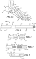
FIG. 1 is a perspective view of a fully assembled fixation system of a preferred embodiment of the present invention incorporating internal fixation, external fixation, and a weight bearing platform; -
FIG. 1A is a perspective view of a human foot; -
FIG. 2 is a side elevational view of a rod component of the internal fixation system shown inFIG. 1 ; -
FIG. 3 is a side elevational view of an intrabody connection mechanism facilitating modularity of the rod component of the internal fixation system; -
FIG. 4 is a side elevational view of an alternative connection mechanism to that shown inFIG. 3 ; -
FIG. 5 is a side elevational view of an alternative end of the rod component; -
FIG. 6 is a top view of a connection plate component of the internal fixation system shown inFIG. 1 ; -
FIG. 7 is a side elevational view of the connection plate component; -
FIG. 8 is a top view of an alternate embodiment of the connection plate component; -
FIG. 9 is a side elevational view of the connection plate component shown inFIG. 8 ; -
FIG. 10 is a front exploded view of the connection plate component shown inFIG. 8 with several fasteners to be used to attach the plate component to bone; -
FIG. 11 is a cross-sectional view of the connection plate component shown inFIG. 8 taken along section line 11-11, connected with the rod component ofFIG. 2 , which is also shown in cross-section for consistency; -
FIG. 12 is a cross-sectional view similar to that ofFIG 11 , but depicting an alternative connection of the rod component to the plate component; -
FIG. 13 is a top view depicting a human foot with several assembled rod-plate constructs of the internal fixation system; -
FIG. 14 is a side elevational view of what is shown inFIG. 13 ; -
FIG. 15 is an exploded elevational view of a shaft component of the internal fixation system; -
FIG. 16 is a partial exploded elevational view of the shaft component ofFIG. 15 shown assembled, along with several fasteners used to attach the shaft component to bone; -
FIG. 17 is a side elevational view of a fully assembled shaft component affixed to two bones prior to reduction; -
FIG. 17A is a side elevational view of what is shown inFIG. 17 , depicting motions that reduce the space between the two bones; -
FIG. 18 is a top view of two shafts implanted in a foot; -
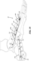
FIG. 19 is a side elevational view of what is shown inFIG. 18 ; -
FIG. 20 is a top view of various internal fixation systems implanted in a foot, including plate-rod constructs, and rods connected to shafts; -
FIG. 21 is a side elevational view of what is shown inFIG. 20 ; -
FIG. 22 is a perspective view of a midfoot plate component of the internal fixation system; -
FIG. 23 is a top plan view of the midfoot plate component implanted in a foot along with the other internal fixation systems depicted inFIGS. 20 and21 ; -
FIG. 24 is a top view of two shaft systems of the internal fixation system implanted in a foot and connected to an external fixation system; -
FIG. 25 is a perspective view of a sole component that is part of the external fixation system; and -
FIG. 26 is an exploded perspective view of various components of the external fixation system, including the sole component forming the weight bearing platform. - For convenience and efficiency of explanation only, the following descriptions of various embodiments of the present invention will be provided with reference to a human foot. However, this part of the body is only meant to be exemplary, non-limiting, and facilitative of a straightforward explanation of the invention, since aspects of the present invention are also envisioned to apply to other skeletal structures.
- Referring to
FIG. 1 , a fixation system 10 for treating Charcot foot and other extremity deformities is depicted. Fixation system 10 comprises an internal fixation system 40 and anexternal fixation system 80. Internal fixation system 40 is comprised of three general subsystems referred to as rod-plate system 50,shaft system 60, andmidfoot plate system 70.External fixation system 80 relevantly includes an optional weight-bearing platform, referred to as sole 400. The various systems, and certain of their various internal and external components, are modular, and may be mixed, matched and used together or independently, as will be discussed in more detail below. - With reference to
FIG. 1A , the human foot comprises theforefoot 12 which includes themetatarsals 14 andphalanges 16, the midfoot 18 which includes the threecuneiform bones 20, the cuboid 22 and thenavicular bone 24, and thehindfoot 26 which includes thetalus 28 andcalcaneus 30. For the sake of conciseness, and because anatomy is well known to those skilled in the art, further reference to the various parts of the foot may be made herein without accompanying reference numbers. - Directional and spatial anatomical terminology that is also used herein is similarly well known to those skilled in the art. For instance, the term "medial" typically means closer to the midline of the body, and "lateral" typically means farther from the midline of the body. Further terms, such as "proximal", "distal", "anterior", "posterior", "superior", "inferior", and other such terms shall have their common and ordinary meanings in the art.
- As used herein, the terms "rod" and "shaft" are chosen to describe the longitudinal members of the internal fixation system for convenience and efficiency of explanation only, and are not meant to be limiting. Thus, "rod" and "shaft" are intended to be non-limiting generic terms that may include such things as a bolt, nail, screw, strut, beam and the like.
- As an overview,
FIGS. 2-14 depict components of rod-plate system 50, which is one of three subsystems of internal fixation system 40.FIGS. 15-19 depict components ofshaft system 60, which is the second of the three subsystems of internal fixation system 40.FIGS. 22-23 depictmidfoot plate system 70, which is the third subsystem of internal fixation system 40.FIGS 20 ,21 , and23 depict various combinations of the various internal fixation subsystems. AndFIGS. 24-26 depict components of theexternal fixation system 80. - With reference to
FIGS. 2-5 ,rod 100 includes abody 108 with afirst end 104 and asecond end 106, which terminates at aflat surface 134. As alternatively depicted inFIG. 5 ,second end 106 may terminate at arounded surface 136. As will be discussed later, roundedsurface 136 is better suited to facilitating the insertion ofrod 100 into a bone canal. -
Rod 100 may be unitary and continuous fromend 104 to end 106, or comprised of two or more joined segments, such asfirst segment 110 joined atconnection 102 tosecond segment 112.Connection 102 generally represents various connection mechanisms that enable the joining of two rod segments together, and will be discussed in more detail, below. -
Body 108 ofrod 100 may have a generally circular transverse cross-sectional shape or may have any other cross-sectional shape such as oval, polygonal or otherwise, as may be suited for various applications.Body 108 may also be roughened, knurled, or otherwise provided with any other surface topography known in the art, for various purposes also known in the art, such as to provide an improved surface for bone adhesion. Furthermore,rod 100, or any of its segments, may be solid or hollow. - The first and
second segments rod 100 are joined together atconnection 102.FIG. 3 depicts a Morse taper-type connection, andFIG. 4 depicts a threaded connection, both of which will be described in more detail, below. Of course, other alternative connections are envisioned. It is further envisioned that in the case of multiple segments of a rod, the same type of connection, or different types of connections, may be employed to join each two segments of arod 100 together, depending on a wide array of factors, as known to those skilled in the art. Similarly, if it is desired to use more than onerod 100 in an implantation, it is envisioned that one segmented rod may be assembled with one type of connection and another segmented rod may be assembled with another type of connection. The rationale for doing so may be due to, for example, the various details and advantages of one type of connection over another, and the resultant properties of the assembled rods with the different connection types. - As mentioned above,
FIG. 3 depicts a Morse-taper type of connection.Second rod segment 112 has amale end 118.Male end 118 includes aconical shoulder 120 that tapers to aprojection 122 having a smaller diameter thanbody 108.First rod segment 110 has afemale end 114 comprising aconical opening 115 significantly decreasing in diameter and leading to aninner bore 116. In general,female end 114 is dimensioned to matingly receivemale end 118. Thus,shoulder 120 has a general correspondence and sizing relationship to opening 115, and similarly,projection 122 to bore 116. More specifically, as is known in the art of Morse tapers, one or both ofmale end 118'sshoulder 120 andprojection 122 have circumferential dimensions that are slightly larger than those of the correspondingfemale end 114'sopening 115 and bore 116. Whenmale end 118 is inserted intofemale end 114, the interference in dimensions results in a press-fit, lockingsecond rod segment 112 tofirst rod segment 110. - If it is desired to not have a rotational preference to the axial alignment, or no keying effect, of
first rod segment 110 tosecond rod segment 112, then the Morse-taper mating surfaces described just above would all have circular cross sections. Of course, if a keying effect would be desired, then the cross-sectional shapes of the mating surfaces may be oval, polygonal, or any other shape known in the art. -
FIG. 4 , as an alternative embodiment, depicts a threadedconnection mechanism 102 betweenfirst rod segment 110 andsecond rod segment 112.Female end 114 offirst rod segment 110 comprises abore 123 withinternal threads 124.Male end 118 ofsecond rod segment 112 comprises acorresponding projection 126 withexternal threads 128.Projection 126 withexternal threads 128 is configured to be matingly received in a threaded fashion in threadedbore 123 offemale end 114. When so assembled,first rod segment 110 is securely connected tosecond rod segment 112. - With reference to
FIG. 5 ,rod 100 may have one or more through-holes 130 configured to receive a fastener (not shown), such as a bone screw, or other fastener known in the art. As will be evident to those skilled in the art, through-hole 130 may be internally threaded so as to threadably receive a corresponding threaded fastener, or may be provided with any other connection mechanism known in the art. In other embodiments, through-hole 130 is smooth and does not contain any form of connection mechanism. Through-hole 130 can receive a fastener to facilitate fixation ofrod 100 within the medullary canal within whichrod 100 may be positioned. Alternatively, through-hole 130 may receive a fastener that is also connected to one or moreother rods 100 which themselves may be positioned and fixed relative to other human bones in the foot to provide fixation across such bones. In yet other embodiments, hole 130 may receive fixation elements fromexternal fixation system 80. -
Slot 132 is depicted onsecond end 106 ofrod 100, and its length is oriented generally along the long axis ofrod 100. The purpose and function ofslot 132 will be discussed in more detail with reference toFIGS. 15-17A , whereshaft 200 has a relativelysimilar slot 240. - With reference to
FIG. 2 ,first end 104 ofrod 100 includes aprojection 138 havingexternal threads 140, and ashoulder 142. As will be described in more detail below,projection 138,external threads 140, andshoulder 142 communicate with connection plate 150 (FIG. 11 ) to form an improved fixation construct. In other embodiments, connection mechanisms other than threads are envisioned such as, for instance, interference fit, cross-screw (FIG. 12 ), nut-and-bolt, ratchet mechanism, and other connection methods known in the art. - In its contemplated embodiments,
rod 100 may be formed of any suitable material known in the art, such as titanium, or other biocompatible materials having mechanical properties suitable for the contemplated uses of fixation system 10. Furthermore,rod 100 may be coated with any suitable biocompatible coating known in the art, such as hydroxyapatite or the like, or may be uncoated, as needed to suit particular mechanical and clinical needs. - In the contemplated embodiments of the present invention,
rods 100 may be provided in various lengths and configured to provide axial stability to the bones in which they reside. In some embodiments, arod 100 is configured to have a length such that therod 100 extends from a portion of a metatarsal into the talus or calcaneus of the hindfoot to provide axial stability.Rods 100 may also be provided in various diameters such as, for instance, a diameter of about 3mm, about 3. 5mm, about 4mm, about 4.5mm or any other diameter known in the art that is suitable for the intended use ofrod 100. As will be evident to one skilled in the art, the selection of one or more appropriatelysized rods 100 may be made by the surgeon in the operating room during surgery, or therods 100 may be selected and prepared prior to surgery. -
FIGS. 6-12 depict embodiments of aconnection plate component 150 that are configured to facilitate connection between a rod, such asrod 100, and a bone, to improve the robustness and rigidity of an internal fixation construct of fixation system 10. As described in an exemplary embodiment herein,plate 150 attaches to a metatarsal of a human foot. However, the description ofplate 150 in the exemplary embodiment is presented for convenience and efficiency of explanation only, and is not meant to be taken as limiting the scope of the invention to the exemplary embodiment. In other embodiments,plate 150 may be fixed to bones other than the metatarsal of a human foot. For instance,plate 150 may be fixed to a metacarpal bone of a human hand or to another human bone.Plate 150 may be generally parallelogram, square, rectangular, oval, or any other shape known in the art that is suitable for fixation to the bone to whichplate 150 is to be affixed. - Referring to
FIGS. 6-12 ,plate 150 includes afirst side 152, asecond side 154 oppositefirst side 152, a thickness T extending therebetween, and aperimeter edge 156. In an embodiment,plate 150 includes fourlobes 158 each having alobe edge 160adjacent lobe 158 and anaperture 162 that extends through the thickness T of theplate 150. In other embodiments,plate 150 may have more orfewer lobes 158, while in still other embodiments,plate 150 may have four lobes, whereinlobes 158 includes more orfewer apertures 162.Apertures 162 are configured to receive fasteners, such asscrews 164, and are generally circular in shape, however other shapes for one ormore apertures 162 may be used, such as slots, for example.Apertures 162 include a first flaredportion 166 onfirst side 152 ofplate 150 and a second flaredportion 168 onsecond side 154 ofplate 150. As will be understood by those skilled in the art, second flaredportions 168 are configured to receive a fastener head therein so that the fastener head may be partially or fully recessed withinplate 150. Additionally, the combination of flaredportions screw 164, throughplate 150. In various embodiments, the flaredportions portions apertures 162 extend perpendicular to thickness T. In such embodiments, fasteners without protruding heads can be used. Additionally, it is envisioned that the one ormore apertures 162 may be designed to accommodate a snap ring (not shown) or other mechanism to prevent ascrew 164 from backing out ofplate 150. Such back-out mechanisms are well known in the art. - Referring to
FIG. 6 , embodiments ofplate 150 may be of various shapes and configurations.Plate 150 includes a long axis A, a short axis C, a length L1 measured as the largest length along the long axis A, and a width W1 measured as the largest width along the short axis C. The shape of theexemplary plate 150 is generally a parallelogram, however the shape and configuration ofplate 150 can be varied. For instance, reducing the length L1 or increasing the width W1 would result in a parallelogram shape that is shaped more like a square. In other embodiments, length L1 can be increased and width W1 can be reduced resulting in a rectangularly shaped parallelogram having one pair of opposing sides ofperimeter edge 156 longer than the other pair. - The length L2 is the shortest distance between opposing sections of
perimeter wall 156 at the intersection of the long axis A and theperimeter wall 156, and width W2 is the shortest distance between opposingperimeter walls 156 at the intersection of the short axis C and theperimeter wall 156. As depicted inFIG. 6 , in an embodiment, the length L2 and width W2 cooperate to provide a generally parallelogram shape. In some embodiments, the length L2 can be increased or reduced to provide a shape that is more rectangular or more square, respectively. In other embodiments, the width W2 can be increased or reduced to provide a shape that is more square or more rectangular, respectively. - The location of the
lobes 158 can also be varied. Length L3 is the length between the center of twoapertures 162 which are both located on the same side of the short axis C, and width W3 is the width between thesame apertures 162. In some embodiments, length L3 can be increased to create a shape that is more diamond-like. In other embodiments, length L3 can be reduced, which results in a shape that is less like a parallelogram. In some embodiments, length L3 can be reduced to zero such that the twoapertures 162 are axially aligned along the short axis C, that is, bothapertures 162 are the same distance from the short axis C. In some embodiments, the width W3 can be increased to create a shape that is more like a square. In other embodiments, width W3 can be reduced, which results in a shape that is more like a rectangle. - The location of each
aperture 162 within itslobe 158 relative to thelobe edge 160 can also be modified. In some embodiments, eachaperture 162 can be disposed closer to itsrespective lobe edge 160, while in other embodiments, eachaperture 162 can be disposed farther from itsrespective lobe edge 160. In still other embodiments, the positions of the apertures relative to their respective lobe edges 160 may be mixed and matched, as may be desirable based on a variety of factors, such as for example, ifplate 150 is made as a custom patient-matched implant that necessitates an altered configuration. - With reference to
FIG. 6 , S1 is the shape of the periphery ofplate 150 along the C axis. S2 is the shape of the periphery ofplate 150 along the A axis. These shapes S1, S2, are depicted as concavities on the periphery ofplate 150. S1, S2 may be complexly formed splines created from transitions of radii of different lengths, or shaped in any other way known in the art, including having no curvature and being straight. In some embodiments, the concavities of S1 and S2 may be grossly exaggerated toward the center of theplate 150, thus resulting in there beingless plate 150 material. In other embodiments, one or both of shapes S1 and S2 may be convexities. - As will be evident to those skilled in the art, there are a myriad of possible configurations of
plate 150. This further facilitates the customizability ofplate 150. For instance,plate 150 may be provided with greater or lesser L3 and W3 dimensions so as to provide more or less distance, respectively, between theapertures 162. Similarly, others of the foregoing dimensions may be arranged to provide an alteredplate 150 according to the surgeon's preference or the particular patient's needs. In some embodiments, various dimensions may be modified together to alter various aspects ofplate 150, such as the locations oflobes 158 relative toperimeter edge 156. - For the foregoing description, it should be understood that, while various lengths and widths were depicted on only one side of axis A or C in
FIG. 6 , such depiction was made for clarity and efficiency of explanation only, and is not meant to be limiting. As such, for any particular length or width described, the same aspects and dimensions on the opposite side of axis A or C exist and can be modified as described above. It should further be understood that the foregoing dimensions do not need to be symmetrical and can be varied from one side of axis A or C relative to the other side of axis A or C, respectively. - Continuing to refer to
FIGS. 6-12 ,plate 150 may include aprojection 180 that extends generally orthogonally away fromfirst side 152 ofplate 150. The purpose ofprojection 180 is to enableplate 150 to be connected to arod 100.Projection 180 includes aninner opening 182 which may be configured to receive afirst end 104 orsecond end 106 of therod 100 ofFIGS. 2-4 , and also includes an external face 184 (FIG. 10 ). In an embodiment,inner opening 182 may be formed withinternal threads 186 to communicate withexternal threads 140 ofprojection 138 of rod 100 (seeFIGS. 2 and11 ). In some embodiments,inner opening 182 is a blind bore (see, for instance,FIGS. 7 and9 ), while in other embodiments,inner opening 182 may extend completely throughprojection 180. In still other embodiments,inner opening 182 may be unthreaded, and the connection betweenopening 182 androd 100 may be a Morse-taper type connection. - With reference to
FIGS. 2 and11 , as will be evident to those skilled in the art, during assembly ofrod 100 toplate 150, asrod 100 is inserted intoopening 182 to a sufficient depth, theshoulder 142 ofrod 100 will contactface 184 ofprojection 180 ofplate 150, thereby halting the movement ofrod 100 intoprojection 180 and ensuring thatrod 100 does not pass beyondprojection 180. - In still other embodiments,
plate 150 and, optionally,rod 100 may be configured with other structures or mechanisms known in the art that facilitate connection ofplate 150 to arod 100. - Referring to the exemplary embodiment of
FIG. 12 ,rod 100 does not havethreads 140 on itsprojection 138 but has a through-hole 178 passing transversely throughprojection 138.Plate 150 is provided with a partially threadedtransverse hole 170 having threads proximal tosecond side 154 ofplate 150.Transverse hole 170 is configured to receive a partially threadedscrew 176 and threadably communicate withscrew 176 in the region shown as 172. Afterrod 100 is inserted into opening 182 ofprojection 180,rod 100's through-hole 178 is axially aligned withtransverse hole 170. Optionally, this alignment may be further facilitated by having cooperating keyed surfaces onprojection 138 andopening 182, as is known in the art. Then, screw 176 is inserted intohole 170 and throughrod 100's through-hole 178, and threadably fixed to plate 150 atregion 172. A portion ofhole 170 may be countersunk, or otherwise formed, to accept in whole or in part, a head of a fastener, such ashead 174 ofscrew 176, to enablehead 174 to be countersunk into theprojection 180 ofplate 150. - Referring to
FIGS. 6-8 and11 , opening 182 inprojection 180 ofplate 150 is formed around longitudinal axis D (FIG. 7 ). In this embodiment, axis D is in the same plane as axis A, which plane is defined by the cross-section line 11-11. Axis D travels through point P which is a point in space withinopening 182. Line E is a reference line drawn parallel to axis A ofplate 150, and offset from axis A by virtue of also traveling through point P. As better seen inFIG. 11 whererod 100 is assembled withplate 150, angle α, which is the angle between axis D and line E, represents the angle betweenrod 100 andplate 150. Angle α may range anywhere from about 5° to about 30° with reference to line E, or may be any other angle that may suit various clinical needs, as is evident to those skilled in the art. In an alternate embodiment (not shown), angle α may even be a negative angle, and in such case,plate 150 would be shaped to accommodaterod 100 projecting through and above itssecond side 154. For example,plate 150 may have an opening through its thickness T to accommodaterod 100, orperimeter edge 156 ofplate 150 may be concavely shaped so as to make room forrod 100 to pass adjacent to plate 150. - In other alternative embodiments, the orientation of
rod 100 to plate 150 may be different. For example, axis D may be oriented at an angle to the plane formed by cross-section line 11-11. This is depicted inFIG. 6 with reference to axis D'. Axis D' is depicted at angle β relative to axis A. Angle β, like angle α, represents the angle ofrod 100 to plate 150 when they are assembled together. Of course, many other alternative configurations are envisioned. - It is further envisioned that to accomplish the angulation of
rod 100 toplate 150, opening 182 inprojection 180 may be designed at different angles as discussed above. Or as will be apparent to those skilled in the art,projection 180, itself, may be designed onplate 150 at different angles and configurations. - Optionally,
plate 150 may be flat, as inFIG. 7 for example, or curved, as inFIG. 9 . The curvature ofplate 150 inFIG. 9 is along long axis A. However, as will be readily apparent to those skilled in the art, many other curves and shapes ofplate 150 are possible, as dictated by different considerations such as manufacturability, or various clinical factors such as anatomical configurations of specific patients. Furthermore, it is contemplated thatplate 150 may be provided as a rigid, non-bendable plate, or alternatively, as a deformable plate, enabling intra-operative bending, as needed. -
Plate 150 may be formed of any one or more suitable biocompatible materials known in the art, such as titanium, PEEK or other biocompatible materials having mechanical properties suitable for the contemplated uses ofplate 150.Plate 150 may also be coated in whole, or in part, with any suitable biocompatible material coating known in the art. - For ease of reference, when
rod 100 is assembled withplate 150, this may also be referred to as a rod-plate construct, and so the rod-plate system 50 may be comprised of one or more rod-plate constructs. -
FIGS. 13 and14 depict an embodiment of the rod-plate system 50, in this case comprising multiple rod-plate constructs implanted in a human foot. Of course, it is readily recognized that the number of rod-plate constructs needed for a particular patient may be determined by the surgeon. - In use, implantation of a rod-plate construct may begin by first aligning and preparing each of the targeted bones for fusion. An appropriately sized opening into the medullary canal of a targeted metatarsal is made on its dorsal aspect at its midportion. A guidewire is then passed through the opening, through the medullary canal, and continues through the other bones to be fused. Optionally, the guidewire may be passed through to the talus or calcaneus. An appropriately-sized cannulated drill is then passed over the guidewire and used to create a passage within the bones to receive
rod 100. -
Rod 100, having the selected and corresponding length to that of the drilled passage, is connected to plate 150. Thesecond end 106 ofrod 100 is then inserted into the opening and through the passage untilprojection 180 ofplate 150 comes to rest within the dorsal aspect opening in the metatarsal. Optionally,plate 150 may be shaped to conform to the topography of the metatarsal after insertion, or beforehand. In other embodiments, a rigidpre-contoured plate 150 may be used. Once the rod-plate construct is in place, fasteners, such asscrews 164, are then used to fixedly connectplate 150 to the metatarsal. -
FIGS. 15-17A depict an exemplary embodiment ofshaft system 60 which is a subsystem of internal fixation system 40.Shaft system 60 may be used independently, or in conjunction with other systems, to facilitate the alignment, reduction and fixation of bones. - The prominent component of
shaft system 60 isshaft 200.Shaft 200 may be a unitary device, or a modular one comprised of various segments that may be joined together, thus enabling customization ofshaft 200. With specific reference toFIG. 15 ,shaft 200 is modular, and is comprised of segments referred to ascap 202,intermediate spacer 204a,intermediate spacer 204b, andbase 206. These segments may each be joined to each other at a connection 203 (shown joined inFIGS. 16-17A ).Connection 203 may be a threaded connection, a Morse-taper type connection, or any other suitable connection known in the art. It is further understood that one or more different types ofconnections 203 may be used to assembleshaft 200. -
Cap 202 is a hollow body comprising abore 215.Cap 202 further comprises afirst end 210 having a roundedterminal portion 214 which facilitatesshaft 200's insertion into bone during implantation, and asecond end 212 wherebore 215 hasinternal threads 216 to enablecap 202 to be connected to another mateable segment ofshaft 200.Cap 202 further has a transverse through-hole 218 to receive fixation element 220 (FIG. 16 ) to fixcap 202, and thereby facilitate fixingshaft 200, to bone. More detail about the optional configurations and uses of through-hole 218 will be discussed in more detail later with reference tobase 206. -
Intermediate spacers hole 218, whilespacer 204b does not have any such through-holes. Bothspacers first end 222, an oppositesecond end 224, and bore 215 extending therebetween, thereby making them hollow. Onfirst end 222, there is aprojection 225 withexternal threads 226.External threads 226 are configured to mate withinternal threads 216, to enable asecure connection 203 therebetween, and thus between any onespacer cap 202. As is evident from this description, the intention is to enable the easy interchangeability and interconnectability of different segments. -
Base 206 also has afirst end 232, an oppositesecond end 234, and bore 215 extending therebetween, thereby making it hollow. On itsfirst end 232,base 206 has asimilar projection 225 withexternal threads 226 as discussed above with reference to other segments, for purposes of interchangeability.Base 206 is also depicted with through-hole 218 to enable its connection to bone. At itssecond end 234,base 206 also has aslot 240 therethrough to facilitate bringing two bone segments together, otherwise known as reduction, as will be discussed in more detail below. Lastly,base 206 hasinternal threads 248 at itssecond end 234. Theseinternal threads 248 are configured to cooperate withexternal threads 226 of the various segments, as well as withexternal threads 256 ofplug 208. Notably,internal threads 248 may run deeper intobore 215 ofbase 206 than comparableinternal threads 216 in other segments. This is becauseinternal threads 248 are also configured to receiveplug 208. -
Plug 208 comprisesbody 255 withexternal threads 256 that are similar toexternal threads 226 on the other segments ofshaft 200, again for interchangeability, acompression element 260, and aninstrument engagement area 265. The insertion ofplug 208 into thesecond end 234 ofbase 206, and its movement throughbore 215, together withslot 240, and the use of a fastener 242 (FIG. 16 ), enables reduction, as will be discussed yet further in more detail below. - With reference to
FIGS. 16-17A , in order to perform reduction, one segment of bone must be stationary, and an adjacent segment of bone must be moved toward the stationary bone segment. In the present embodiment, bone B1 is the stationary bone.Shaft 200 is fixed to bone B1 withscrew 220 positioned through through-hole 218 inbase 206. Notably, through-hole 218 also provides for further variability of fixation methods ofshaft 200 to bone as discussed next. - It is recognized that there are at least two common approaches to fixating
shaft 200 in space relative to bone, among various other approaches known in the art. In one such common approach, this is accomplished by fixing proximal bone portion Bp toshaft 200. In the other common approach, this is accomplished by pinningshaft 200 in between two segments of bone. - With reference to the first approach, when
shaft 200 is in a bone canal (FIG. 17 ), abore 230 is drilled from the proximal bone surface Bp of proximal bone B1 to the exterior ofshaft 200.Bore 230 is coaxial with through-hole 218 and sized to allow the head ofscrew 220 to pass.Screw 220 is then inserted throughbore 230 and threaded into a threaded version of through-hole 218. As is evident, and known in the art, it is not necessary forscrew 220 to go all the way throughbase 206, so long as there is sufficient threaded engagement in the first area of contact betweenscrew 220 andbase 206. Of course, if more thread engagement is desired, screw 220 may be progressed further to threadably engage base 206 at its second area of contact withbase 206. As will be readily recognized, the approach just described from bone surface Bp may be similarly accomplished from the opposite distal bone surface Bd. For this reason, it is desirable to have through-hole 218 fully threaded. - With respect to the second approach of fixating
shaft 200 in space relative to bone, the intention is forscrew 220 to enter throughbore 230, completely extend throughshaft 200, and threadably purchase bone portion Bd. While this approach may better call for through-hole 218 to be unthreaded, to increase the variability of usage ofshaft 200, the threaded version of through-hole 218 may continue to be employed. Of course, having described the foregoing, it will be readily recognized that various alternatives and permutations of the above configurations of structure and usage may be employed. Additionally, it is noted that through-hole 218 has the same characteristics as through-hole 130 ofrod 100. - With further reference to
FIGS. 16-17A , in the context of reduction, the bone segment that will be moved toward stationary bone segment B1 is movable bone segment B2. Of course, it is generally recognized that movement is relative. In similar fashion as described for puttingscrew 220 through through-hole 218 ofbase 206, a partially threadedscrew 242 is put throughslot 240, and specifically throughslot area 244 which is most distal to base 206'sfirst end 232, and screwed into bone B2. Plug 208 may be introduced into threaded engagement withinternal threads 248 ofsecond end 234 ofbase 206 before or after insertion ofscrew 242, and positioned atslot area 244. A driver (not shown) is then engaged to plug 208'sinstrument engagement area 265, and actuated so as to rotateplug 208 in direction F (FIG. 17A ), thus translatingplug 208 towardsslot area 246 by virtue of the translational component of threaded rotation. In so doing,compression element 260 ofplug 208 pushes screw 242 linearly alongslot 240 fromslot area 244 to slotarea 246, a distance M. Consequently, this pushes bone segment B2 towards bone segment B1, which is fixedly connected to base 206 via through-hole 218, the same distance M, thus producing reduction. - It will be readily understood by those skilled in the art that the reduction mechanism described above, inclusive of such elements as
slot 240 and plug 208, may be positioned on any other one or more segments ofshaft 200 for increased variability of the segments ofshaft 200. Of course, other means to rotate or otherwise advanceplug 208 may be needed in instances where itsinstrument engagement area 265 is not accessible as in the embodiment described above. - While
slot 240 has been described in the context and functionality depicted with reference toshaft 200, a somewhatsimilar slot 132 is positioned on rod 100 (FIG. 5 ) as mentioned earlier. The specific mechanism forreduction using slot 132 will be different from that described forslot 240, but such other ways to perform reduction are known in the art. For example, with reference toFIG. 24 , if apin 310 were inserted throughslot 132 ofrod 100 into one bone, and ascrew 220 were inserted through hole 130 ofrod 100 into another bone, then a surgeon may manually grip and translatepin 310 and screw 220 toward each other, thereby bringing the two bones together. - The ability to rotationally align one segment of
shaft 200 to a desired position relative to another segment ofshaft 200, for a variety of purposes, is an engineering function that has many different solutions known in the art. For example, with reference toFIG. 16 , it may be desirable to have through-hole 218 oncap 202 oriented 30° in either direction from where it is shown. Similarly, on thesame shaft 200, it may be desired for through-hole 218 on spacer 204a to be oriented 15° from where it is shown. One way to accomplish such desired alignment of through-holes 218 in an assembledshaft 200 is to have keyed, timed, orprecision threads - The ability to target and insert
screws rods 100 andshafts 200 is also an engineering function that has various different solutions known in the art. For example, targeting jigs are known to facilitate the location and identify the orientation of through-holes 218 whenshaft 200 is inside bone.Rods 100 andshafts 200 may be configured to cooperate with such targeting jigs. - As was noted earlier with respect to
rod 100,shaft 200, and the various other elements described above, may be formed of any suitable material known in the art. For example,shaft 200 may be formed of titanium, or other biocompatible materials having mechanical properties suitable for its contemplated uses. Furthermore,shaft 200 may be coated with any suitable biocompatible coating known in the art, such as hydroxyapatite or the like, or may be uncoated, as needed to suit particular mechanical and clinical needs. - Notably, as will be apparent to those skilled in the art,
shafts 200 may be solid rather than hollow, androds 100 may be hollow rather than solid. Of course, various other adjustments to their respective features may then be made to result in those features maintaining their respective intended functionalities. For example, ifshaft 200 were solid rather than hollow,second end 234 ofbase 206 would still maintain a hollow passageway to enableplug 208 to travel therethrough to effectuate reduction. - Referring to
FIGS. 18 and19 , twoshafts 200 ofshaft system 60 are shown implanted in a human foot. Themedial shaft 200 is assembled from acap 202, followed by twospacers 204a, and then abase 206, and is oriented such thatbase 206 is located in the first metatarsal, and thecap 202 is in the talus. Thelateral shaft 200 is assembled from anothercap 202 and abase 206. It is oriented such thatbase 206 is in the calcaneus, andcap 202 is in the cuboid. Eachshaft 200 is depicted as fixed in place to bone byvarious screws - Each of the bones targeted for fusion are first manually aligned and prepared for accepting
shaft system 60. For example, to implant themedial shaft 200, the first metatarsal phalangeal joint is exposed via a dorsal incision. A guidewire to direct reaming of the medullary canal is then introduced near the center of the metatarsal head, directed through the metatarsal body, medial cuneiform navicular, and into the talar neck. Reaming is then conducted iteratively over the guidewire until a canal having an appropriate internal diameter to receiveshaft 200 is formed through the bones. Of course, it is recognized that various anatomical landmarks and sizes of bones will ultimately determine the selection of the diameter and length of the canal, and therefore the diameter and length ofshaft 200 to be used in it, as well as which segments ofshaft 200 should be selected and the order in which they should be assembled. - Prior to insertion of
shaft 200, it may be connected to a targeting jig (not shown). The targeting jig projects the positions of the relevant through-holes onshaft 200, such asholes 218, and thus enables a surgeon to accurately placescrews 220 through the targeting jig directly into or through each targetedhole 218, for example, as the case may be, aftershaft 200 is placed in the reamed bone canal. - Once the targeting jig is attached to the
medial shaft 200,medial shaft 200 is then inserted into the reamed bone canal. Ascrew 220 is then placed through the jig and throughhole 218 ofcap 202 which is located in the talus. Then, screw 242 is placed through the jig and throughslot 240, which, in such embodiment, is in the first metatarsal. Plug 208, located insecond end 234 ofbase 206 is then rotationally actuated to translate axially alongslot 240, thus compressing all the bones betweenscrew 242 and screw 220 alongshaft 200, to a desired orientation, at which point,other screws 220 will be inserted throughshaft 200 to lock the compressed bones in place relative toshaft 200. Alternatively, some or all of the compression may also be performed by other techniques known in the art. - In light of the foregoing, the preparation of bones, the selection, assembly, and insertion of
lateral shaft 200, and the reduction and fixation of the associated bones, will be apparent to those skilled in the art. - With reference to
FIGS. 20-21 , there is depicted the implanted combination of a rod-plate system 50 andshaft system 60. Specifically, there are two rod-plate constructs, and twoshafts 200. Notably, arod 100 may be connected to ashaft 200, and is depicted as such. This may be accomplished usingscrew 220, or by other means. As will be apparent to those skilled in the art, any number, combination, and configuration of rod-plate constructs and shafts may be employed, and also connected to each other at different points, as necessary to address various clinical needs. -
FIG. 22 depicts a midfoot component in the form ofplate 280, havingscrew holes 281 adapted to receive screws 282 (FIG. 23 ) that attachplate 280 to bone.Plate 280 is generally known in the art.Plate 280 may be malleable, to enable it to be shaped in situ to conform to target anatomy to which it will be attached, or provided in multiple generic rigid shapes, or otherwise custom manufactured through patient-matching technologies. It is intended to be used on its own, or in combination with one or more systems and subsystems of fixation system 10. -
FIG. 23 depictsplate 280 implanted in a foot in combination with rod-plate constructs andshafts 200, wherein certain of therods 100 andshafts 200 are interconnected. The possibility to combine all these subsystems offers increased variability and flexibility to treat a greater variety of clinical needs. -
FIG. 24 depicts an internal fixation subsystem, namelyshaft system 60, connected to anexternal fixation system 80.External fixation system 80 comprises one ormore frames 302 each having a plurality ofopenings 304, a plurality ofconnectors 306, and pins 310.Pins 310 are depicted as partially threaded on their distal ends, and may also optionally be unthreaded, or fully threaded, as is known in the art. This basicexternal fixation system 80 is also well known in the art. - Notably, an aspect of the present invention is the connection of
external fixation system 80 to theshaft system 60, as depicted inFIG. 24 . Specifically,frame 302 is connected usingpins 310 inserted throughconnectors 306 toshafts 200. It is thusly evident that many other configurations, arrangements and connections ofexternal fixation system 80 with one or more of certain subsystems of internal fixation system 40 are possible. For example,external fixation system 80 may be connected to an implanted rod-plate system 50. - The added ability to combine and connect
external fixation system 80 with the various subsystems of internal fixation system 40 increases yet further the variability and flexibility of the overall fixation system 10 to treat a yet greater variety of clinical needs. -
FIG. 25 depicts asole component 400 ofexternal fixation system 80.Sole component 400 is intended to be used in conjunction withexternal fixation system 80 and is meant to provide a weight-bearing platform underneath a patient's foot to enable a patient with fixation system 10 to walk. -
Sole 400 comprises ahousing 402 adapted to hold aremovable liner 404 therein. With reference fromfront 410 to back 412,housing 402 has atop surface 406,side walls 407 and abottom surface 408 that spanshousing 402 fromfront 410 to back 412.Bottom surface 408 is the surface that comes in contact with the ground when a patient walks while wearing fixation system 10. As such, its shape, texture and materials may be adapted as known in the art to facilitate safer walking. For example,bottom surface 408 may be made of, or coated with, rubber to increase the coefficient of friction between sole 400 and the ground, thus diminishing the chances of a patient slipping while they walk with fixation system 10. Other embodiments are envisioned to accomplish this goal. - The profile of
bottom surface 408 may be a complex series of continuous curves, such as a tighter curve toward the back 412, which may be known as the heel-strike area, eventually transitioning to a gradual curve toward the front 410, over which the forefoot rolls during gait. Of course, other shapes are contemplated. -
Liner 404 may include an inflatable air bladder (not specifically shown) and be filled with any appropriate fluid. The bladder may have a valve (not specifically shown) through which air or other fluid may be introduced or evacuated to achieve the optimal density and size to support a particular weight or pressure requirement.Liner 404 may optionally be housed in a fabric shell (not specifically shown). The shell can be moisture wicking and machine washable for easy cleaning and maintenance. The shell may also be removable via a zipper, hook-and-loop fasteners, snaps, and the like. -
Sole 400 also hasslots 424, enabling it to be connected to frame 302 (FIG. 26 ), as will be discussed in more detail below.Slots 424 may be formed within the material ofhousing 402, or may alternatively be solid tubes affixed to either the inside or outside ofhousing 402, as may be readily understood by those skilled in the art. -
FIG. 26 is an exploded view of certain components ofexternal fixation system 80 used to assemble sole 400 to frame 302. More specifically,connectors 306 have threadedopenings 307 on their various faces, enabling them to be connected to frame 302 and to othercomponents using bolts 308, thus making them universal. -
Struts 426 are used to connect sole 400 to frame 302.Struts 426 haveeyelets 428 to enable such a connection. For example, afterconnectors 306 are connected to frame 302 withbolts 308,eyelets 428 ofstruts 426 would be aligned withconnectors 306, andadditional bolts 308 would be put througheyelets 428 and screwed intoconnectors 306, thus pinning and fixingstruts 426 to frame 302.Struts 426 shall also be connected to sole 400 in any variety of ways known to those skilled in the art. For example, struts 426 may be inserted and glued intoslots 424. -
Struts 426 may be of unitary construction, or alternatively, may be comprised of two or morecomponents enabling strut 426 to expand and compress as well as be fixed in place at a desired length.Struts 426 may also be made from various materials, from stiff metals, to more elastomeric materials that may further facilitate absorption of striking forces during gait. - Having thus described the invention in detail, it is to be understood that the foregoing description is not intended to limit the scope thereof. It will be understood that the embodiments of the present disclosure described herein are merely exemplary and that a person skilled in the art may make any variations and modification falling under the scope of the claims without departing from the scope of the disclosure. All such variations and modifications, including those discussed above, are intended to be included within the scope of the disclosure.
Claims (8)
- A fixation system (10) for immobilizing a skeletal structure, comprising:an internal fixation system (40) comprisinga rod-plate system (50), anda shaft system (60); andan external fixation system (80);wherein the rod-plate system (50) comprises
a rod (100) affixed to a plate (150), the rod (100) being adapted to be positioned in a bone canal, and the plate (150) being adapted to be positioned on bone near the bone canal;wherein the shaft system (60) comprises a shaft (200) with a longitudinal axis, a slot (240) on the shaft (200) oriented in the direction of the longitudinal axis, and a hole (218) on the shaft (200) oriented at an angle to the longitudinal axis, the shaft (200) further adapted to be positioned in a bone canal and configured to move two bone segments that comprise the bone canal toward each other;wherein the external fixation system (80) comprises a frame (302) connected to a sole (400), the sole having a bottom (408) adapted to contact ground; andwherein the rod-plate system (50) is configured to be connected to the shaft system (60) when both systems are positioned in bone. - The fixation system (10) of claim 1, wherein the external fixation system (80) further comprises a pin (310), and the external fixation system (80) is configured to be connected to the rod-plate system (50) or the shaft system (60) via the pin (310) when the rod-plate system (50) or the shaft system (60) is positioned in bone.
- The fixation system (10) of claim 1, further comprising a midfoot plate system (70) configured to be attached to bone, the midfoot plate system (70) comprising a plate and a fastener.
- The fixation system (10) of claim 1, wherein the rod (100) of the rod-plate system (50) is modularly comprised of multiple segments each joinable by a connection.
- The fixation system (10) of claim 1, wherein the plate (150) of the rod-plate system (50) comprises a first side (152) adapted to face bone, an opposite second side (154), a length, a width, a plate axis along the length, and a projection (180) extending from the first side (152).
- The fixation system (10) of claim 5, wherein the projection (180) includes an opening (182) to communicate with the rod (100) of the rod-plate system (50).
- The fixation system (10) of claim 6, wherein the opening (182) in the projection (180) communicates with the rod (100) via a threaded connection.
- The fixation system (10) of claim 6, wherein the opening (182) is cylindrical and has a longitudinal opening axis, and the opening (182) is oriented such that the opening axis is at an angle to the plate axis.
Applications Claiming Priority (2)
| Application Number | Priority Date | Filing Date | Title |
|---|---|---|---|
| US201862626324P | 2018-02-05 | 2018-02-05 | |
| PCT/US2019/016257 WO2019152784A2 (en) | 2018-02-05 | 2019-02-01 | Implants and methods for treating charcot foot and other conditions |
Publications (4)
| Publication Number | Publication Date |
|---|---|
| EP3749235A2 EP3749235A2 (en) | 2020-12-16 |
| EP3749235A4 EP3749235A4 (en) | 2022-03-02 |
| EP3749235B1 true EP3749235B1 (en) | 2025-04-09 |
| EP3749235C0 EP3749235C0 (en) | 2025-04-09 |
Family
ID=67479990
Family Applications (1)
| Application Number | Title | Priority Date | Filing Date |
|---|---|---|---|
| EP19746853.1A Active EP3749235B1 (en) | 2018-02-05 | 2019-02-01 | Fixation systems for treating charcot foot and other conditions |
Country Status (5)
| Country | Link |
|---|---|
| US (2) | US11446061B2 (en) |
| EP (1) | EP3749235B1 (en) |
| CN (1) | CN111683611B (en) |
| ES (1) | ES3032757T3 (en) |
| WO (1) | WO2019152784A2 (en) |
Families Citing this family (4)
| Publication number | Priority date | Publication date | Assignee | Title |
|---|---|---|---|---|
| WO2019152784A2 (en) * | 2018-02-05 | 2019-08-08 | Bespa Global, Llc | Implants and methods for treating charcot foot and other conditions |
| US20230190342A1 (en) * | 2021-12-17 | 2023-06-22 | Mark Robert BRINKER | Surgical device |
| CN115998407B (en) * | 2023-03-29 | 2023-06-06 | 中国人民解放军总医院第一医学中心 | Reduction fixing device for fracture correction |
| US20260199163A1 (en) * | 2024-11-01 | 2026-07-16 | Automated Intelligent Robotics Llc | Automated dynamic patient positioning system for robotic surgery |
Family Cites Families (30)
| Publication number | Priority date | Publication date | Assignee | Title |
|---|---|---|---|---|
| AUPN289395A0 (en) | 1995-05-09 | 1995-06-01 | University Of Western Australia, The | Intramedullary bone nail |
| WO2004014243A1 (en) * | 2002-08-10 | 2004-02-19 | William H Simon | Method and apparatus for repairing the mid-food region via an intermedullary nail |
| US8012112B2 (en) | 2006-02-14 | 2011-09-06 | Alessandro Aldo Barberio | Orthopedic braces and casts with aerating arrangements |
| ITVR20070017A1 (en) * | 2007-02-01 | 2008-08-02 | Giuseppe Lodola | PLANT FOR FIXING TWO BONE FRAMES ONE TO THE OTHER IN OSTEOTOMY INTERVENTIONS |
| US8192434B2 (en) * | 2008-05-02 | 2012-06-05 | Huebner Randall J | External fixation and foot-supporting device |
| US20100121325A1 (en) * | 2008-06-24 | 2010-05-13 | Jeff Tyber | Hybrid intramedullary fixation assembly and method of use |
| US8764750B2 (en) * | 2008-09-11 | 2014-07-01 | The Board Of Regents Of The University Of Texas System | Foot, ankle and lower extremity compression and fixation system and related uses |
| US8540715B2 (en) * | 2008-11-10 | 2013-09-24 | Temple University—Of the Commonwealth System of Higher Education | Locking rod fusion device |
| US8591513B2 (en) * | 2008-12-05 | 2013-11-26 | DePuy Synthes Products, LLC | Anchor-in-anchor system for use in bone fixation |
| US8986353B2 (en) * | 2009-07-09 | 2015-03-24 | Orthohelix Surgical Designs, Inc. | Osteotomy plate, plate driver and method for their use |
| US8764807B2 (en) * | 2010-06-10 | 2014-07-01 | Arthrex, Inc. | Calcaneus step plate |
| US8945128B2 (en) * | 2010-08-11 | 2015-02-03 | Stryker Trauma Sa | External fixator system |
| US20130158608A1 (en) * | 2011-12-20 | 2013-06-20 | Osteomed L.P. | Plate and cannulated transfixation screw system for human implant |
| US9060822B2 (en) * | 2011-12-28 | 2015-06-23 | Orthohelix Surgical Designs, Inc. | Orthopedic compression plate and method of surgery |
| WO2013123366A1 (en) * | 2012-02-16 | 2013-08-22 | Paragon 28, Inc. | Charco-resis implant, alignment instrument, system and method of use |
| US9125695B2 (en) * | 2012-10-18 | 2015-09-08 | Bespa, Inc. | Ankle fusion nail apparatus and method |
| CA2967478C (en) * | 2013-03-14 | 2019-05-14 | Wright Medical Technology, Inc. | Intramedullary ankle technique and system |
| EP3677236A3 (en) * | 2014-05-02 | 2020-11-18 | Wright Medical Technology, Inc. | Circular fixator system |
| DE102014208283B4 (en) * | 2014-05-02 | 2019-01-10 | Peter Brehm | Apparatus for attaching a positioning means to a patient's bone, apparatus for processing a patient's bone and hip implant system |
| JP6629841B2 (en) * | 2014-08-28 | 2020-01-15 | バイオメット シー.ブイ. | Bone plate system and method |
| US10226292B2 (en) * | 2015-06-08 | 2019-03-12 | Andrew Lundquist | Combined intramedullary-extramedullary bone stabilization and alignment system |
| US10182845B2 (en) * | 2015-07-23 | 2019-01-22 | William P. Grant | Bone securement apparatus and method |
| US10687874B2 (en) * | 2015-08-27 | 2020-06-23 | Globus Medical, Inc | Proximal humeral stabilization system |
| EP3150151B1 (en) * | 2015-09-29 | 2018-09-19 | Orthofix S.r.l. | Walking skates system removably coupled to an external ring fixation system |
| US10624674B2 (en) * | 2015-11-12 | 2020-04-21 | Wright Medical Technology, Inc. | Circular fixator system and method |
| US11033303B2 (en) * | 2017-03-13 | 2021-06-15 | Extremity Medical, Llc | Calcaneal cross medullary plate |
| US10779867B2 (en) * | 2017-04-06 | 2020-09-22 | Extremity Medical Llc | Orthopedic plate with modular peg and compression screw |
| US11185356B2 (en) * | 2017-12-08 | 2021-11-30 | Paragon 28, Inc. | Bone fixation assembly, implants and methods of use |
| WO2019152784A2 (en) * | 2018-02-05 | 2019-08-08 | Bespa Global, Llc | Implants and methods for treating charcot foot and other conditions |
| US10413328B1 (en) * | 2018-03-15 | 2019-09-17 | New Standard Device, LLC | External fixation for the correction of bone deformity and trauma |
-
2019
- 2019-02-01 WO PCT/US2019/016257 patent/WO2019152784A2/en not_active Ceased
- 2019-02-01 CN CN201980011418.3A patent/CN111683611B/en active Active
- 2019-02-01 ES ES19746853T patent/ES3032757T3/en active Active
- 2019-02-01 US US16/963,775 patent/US11446061B2/en active Active
- 2019-02-01 EP EP19746853.1A patent/EP3749235B1/en active Active
-
2022
- 2022-08-08 US US17/882,833 patent/US12396757B2/en active Active
Also Published As
| Publication number | Publication date |
|---|---|
| EP3749235A4 (en) | 2022-03-02 |
| CN111683611B (en) | 2023-12-26 |
| US11446061B2 (en) | 2022-09-20 |
| CN111683611A (en) | 2020-09-18 |
| WO2019152784A2 (en) | 2019-08-08 |
| EP3749235C0 (en) | 2025-04-09 |
| ES3032757T3 (en) | 2025-07-24 |
| US20220370099A1 (en) | 2022-11-24 |
| US12396757B2 (en) | 2025-08-26 |
| WO2019152784A3 (en) | 2020-04-23 |
| EP3749235A2 (en) | 2020-12-16 |
| US20210038261A1 (en) | 2021-02-11 |
Similar Documents
| Publication | Publication Date | Title |
|---|---|---|
| US12396757B2 (en) | Implants and methods for treating Charcot foot and other conditions | |
| CN102573682B (en) | Fixed system, intramedullary fixation assembly and using method thereof | |
| JP7470531B2 (en) | Apparatus and method for repairing bone defects | |
| US20240341824A1 (en) | Bone fixation device and method of use | |
| US8920476B2 (en) | Fixation system, an intramedullary fixation assembly and method of use | |
| AU2012296567B2 (en) | Targeting assembly for a compression nail system | |
| US8303589B2 (en) | Fixation system, an intramedullary fixation assembly and method of use | |
| US20120265301A1 (en) | Intraosseous fixation assembly for an osteotomy and method of use | |
| US10869701B2 (en) | Joint compression instrumentation and methods | |
| US20250160909A1 (en) | Implants, systems, and methods of use | |
| JP2024070261A (en) | Sagittal adjustment slot in plate used with intramedullary nail | |
| JP2021065704A (en) | Proximal humeral stabilization systems and methods thereof |
Legal Events
| Date | Code | Title | Description |
|---|---|---|---|
| STAA | Information on the status of an ep patent application or granted ep patent |
Free format text: STATUS: THE INTERNATIONAL PUBLICATION HAS BEEN MADE |
|
| PUAI | Public reference made under article 153(3) epc to a published international application that has entered the european phase |
Free format text: ORIGINAL CODE: 0009012 |
|
| STAA | Information on the status of an ep patent application or granted ep patent |
Free format text: STATUS: REQUEST FOR EXAMINATION WAS MADE |
|
| 17P | Request for examination filed |
Effective date: 20200629 |
|
| AK | Designated contracting states |
Kind code of ref document: A2 Designated state(s): AL AT BE BG CH CY CZ DE DK EE ES FI FR GB GR HR HU IE IS IT LI LT LU LV MC MK MT NL NO PL PT RO RS SE SI SK SM TR |
|
| AX | Request for extension of the european patent |
Extension state: BA ME |
|
| DAV | Request for validation of the european patent (deleted) | ||
| DAX | Request for extension of the european patent (deleted) | ||
| A4 | Supplementary search report drawn up and despatched |
Effective date: 20220202 |
|
| RIC1 | Information provided on ipc code assigned before grant |
Ipc: A61B 17/80 20060101ALI20220127BHEP Ipc: A61B 17/72 20060101ALI20220127BHEP Ipc: A61B 17/64 20060101AFI20220127BHEP |
|
| GRAP | Despatch of communication of intention to grant a patent |
Free format text: ORIGINAL CODE: EPIDOSNIGR1 |
|
| STAA | Information on the status of an ep patent application or granted ep patent |
Free format text: STATUS: GRANT OF PATENT IS INTENDED |
|
| RIC1 | Information provided on ipc code assigned before grant |
Ipc: A61B 17/80 20060101ALI20241021BHEP Ipc: A61B 17/72 20060101ALI20241021BHEP Ipc: A61B 17/64 20060101AFI20241021BHEP |
|
| INTG | Intention to grant announced |
Effective date: 20241108 |
|
| GRAS | Grant fee paid |
Free format text: ORIGINAL CODE: EPIDOSNIGR3 |
|
| GRAA | (expected) grant |
Free format text: ORIGINAL CODE: 0009210 |
|
| STAA | Information on the status of an ep patent application or granted ep patent |
Free format text: STATUS: THE PATENT HAS BEEN GRANTED |
|
| AK | Designated contracting states |
Kind code of ref document: B1 Designated state(s): AL AT BE BG CH CY CZ DE DK EE ES FI FR GB GR HR HU IE IS IT LI LT LU LV MC MK MT NL NO PL PT RO RS SE SI SK SM TR |
|
| REG | Reference to a national code |
Ref country code: GB Ref legal event code: FG4D |
|
| REG | Reference to a national code |
Ref country code: CH Ref legal event code: EP |
|
| REG | Reference to a national code |
Ref country code: DE Ref legal event code: R096 Ref document number: 602019068409 Country of ref document: DE |
|
| REG | Reference to a national code |
Ref country code: IE Ref legal event code: FG4D |
|
| U01 | Request for unitary effect filed |
Effective date: 20250425 |
|
| U07 | Unitary effect registered |
Designated state(s): AT BE BG DE DK EE FI FR IT LT LU LV MT NL PT RO SE SI Effective date: 20250506 |
|
| REG | Reference to a national code |
Ref country code: ES Ref legal event code: FG2A Ref document number: 3032757 Country of ref document: ES Kind code of ref document: T3 Effective date: 20250724 |
|
| PG25 | Lapsed in a contracting state [announced via postgrant information from national office to epo] |
Ref country code: GR Free format text: LAPSE BECAUSE OF FAILURE TO SUBMIT A TRANSLATION OF THE DESCRIPTION OR TO PAY THE FEE WITHIN THE PRESCRIBED TIME-LIMIT Effective date: 20250710 Ref country code: NO Free format text: LAPSE BECAUSE OF FAILURE TO SUBMIT A TRANSLATION OF THE DESCRIPTION OR TO PAY THE FEE WITHIN THE PRESCRIBED TIME-LIMIT Effective date: 20250709 |
|
| PG25 | Lapsed in a contracting state [announced via postgrant information from national office to epo] |
Ref country code: PL Free format text: LAPSE BECAUSE OF FAILURE TO SUBMIT A TRANSLATION OF THE DESCRIPTION OR TO PAY THE FEE WITHIN THE PRESCRIBED TIME-LIMIT Effective date: 20250409 |
|
| PG25 | Lapsed in a contracting state [announced via postgrant information from national office to epo] |
Ref country code: HR Free format text: LAPSE BECAUSE OF FAILURE TO SUBMIT A TRANSLATION OF THE DESCRIPTION OR TO PAY THE FEE WITHIN THE PRESCRIBED TIME-LIMIT Effective date: 20250409 |
|
| PG25 | Lapsed in a contracting state [announced via postgrant information from national office to epo] |
Ref country code: RS Free format text: LAPSE BECAUSE OF FAILURE TO SUBMIT A TRANSLATION OF THE DESCRIPTION OR TO PAY THE FEE WITHIN THE PRESCRIBED TIME-LIMIT Effective date: 20250709 |
|
| PG25 | Lapsed in a contracting state [announced via postgrant information from national office to epo] |
Ref country code: IS Free format text: LAPSE BECAUSE OF FAILURE TO SUBMIT A TRANSLATION OF THE DESCRIPTION OR TO PAY THE FEE WITHIN THE PRESCRIBED TIME-LIMIT Effective date: 20250809 |
|
| PG25 | Lapsed in a contracting state [announced via postgrant information from national office to epo] |
Ref country code: SM Free format text: LAPSE BECAUSE OF FAILURE TO SUBMIT A TRANSLATION OF THE DESCRIPTION OR TO PAY THE FEE WITHIN THE PRESCRIBED TIME-LIMIT Effective date: 20250409 |
|
| PG25 | Lapsed in a contracting state [announced via postgrant information from national office to epo] |
Ref country code: CZ Free format text: LAPSE BECAUSE OF FAILURE TO SUBMIT A TRANSLATION OF THE DESCRIPTION OR TO PAY THE FEE WITHIN THE PRESCRIBED TIME-LIMIT Effective date: 20250409 |
|
| PG25 | Lapsed in a contracting state [announced via postgrant information from national office to epo] |
Ref country code: SK Free format text: LAPSE BECAUSE OF FAILURE TO SUBMIT A TRANSLATION OF THE DESCRIPTION OR TO PAY THE FEE WITHIN THE PRESCRIBED TIME-LIMIT Effective date: 20250409 |
|
| PLBE | No opposition filed within time limit |
Free format text: ORIGINAL CODE: 0009261 |
|
| STAA | Information on the status of an ep patent application or granted ep patent |
Free format text: STATUS: NO OPPOSITION FILED WITHIN TIME LIMIT |
|
| REG | Reference to a national code |
Ref country code: CH Ref legal event code: L10 Free format text: ST27 STATUS EVENT CODE: U-0-0-L10-L00 (AS PROVIDED BY THE NATIONAL OFFICE) Effective date: 20260218 |
|
| 26N | No opposition filed |
Effective date: 20260112 |
|
| U20 | Renewal fee for the european patent with unitary effect paid |
Year of fee payment: 8 Effective date: 20260226 |
|
| PGFP | Annual fee paid to national office [announced via postgrant information from national office to epo] |
Ref country code: GB Payment date: 20260226 Year of fee payment: 8 |
|
| PGFP | Annual fee paid to national office [announced via postgrant information from national office to epo] |
Ref country code: ES Payment date: 20260311 Year of fee payment: 8 |