EP3749015A1 - Channel transmission method and device, and computer storage medium - Google Patents
Channel transmission method and device, and computer storage medium Download PDFInfo
- Publication number
- EP3749015A1 EP3749015A1 EP18904666.7A EP18904666A EP3749015A1 EP 3749015 A1 EP3749015 A1 EP 3749015A1 EP 18904666 A EP18904666 A EP 18904666A EP 3749015 A1 EP3749015 A1 EP 3749015A1
- Authority
- EP
- European Patent Office
- Prior art keywords
- bwp
- terminal
- channel
- control information
- moment
- Prior art date
- Legal status (The legal status is an assumption and is not a legal conclusion. Google has not performed a legal analysis and makes no representation as to the accuracy of the status listed.)
- Granted
Links
Images



Classifications
-
- H—ELECTRICITY
- H04—ELECTRIC COMMUNICATION TECHNIQUE
- H04L—TRANSMISSION OF DIGITAL INFORMATION, e.g. TELEGRAPHIC COMMUNICATION
- H04L5/00—Arrangements affording multiple use of the transmission path
- H04L5/0091—Signalling for the administration of the divided path, e.g. signalling of configuration information
- H04L5/0092—Indication of how the channel is divided
-
- H—ELECTRICITY
- H04—ELECTRIC COMMUNICATION TECHNIQUE
- H04L—TRANSMISSION OF DIGITAL INFORMATION, e.g. TELEGRAPHIC COMMUNICATION
- H04L5/00—Arrangements affording multiple use of the transmission path
- H04L5/003—Arrangements for allocating sub-channels of the transmission path
- H04L5/0044—Allocation of payload; Allocation of data channels, e.g. PDSCH or PUSCH
-
- H—ELECTRICITY
- H04—ELECTRIC COMMUNICATION TECHNIQUE
- H04L—TRANSMISSION OF DIGITAL INFORMATION, e.g. TELEGRAPHIC COMMUNICATION
- H04L5/00—Arrangements affording multiple use of the transmission path
- H04L5/003—Arrangements for allocating sub-channels of the transmission path
- H04L5/0078—Timing of allocation
-
- H—ELECTRICITY
- H04—ELECTRIC COMMUNICATION TECHNIQUE
- H04L—TRANSMISSION OF DIGITAL INFORMATION, e.g. TELEGRAPHIC COMMUNICATION
- H04L5/00—Arrangements affording multiple use of the transmission path
- H04L5/0091—Signalling for the administration of the divided path, e.g. signalling of configuration information
- H04L5/0096—Indication of changes in allocation
- H04L5/0098—Signalling of the activation or deactivation of component carriers, subcarriers or frequency bands
-
- H—ELECTRICITY
- H04—ELECTRIC COMMUNICATION TECHNIQUE
- H04W—WIRELESS COMMUNICATION NETWORKS
- H04W36/00—Hand-off or reselection arrangements
- H04W36/06—Reselecting a communication resource in the serving access point
-
- H—ELECTRICITY
- H04—ELECTRIC COMMUNICATION TECHNIQUE
- H04W—WIRELESS COMMUNICATION NETWORKS
- H04W72/00—Local resource management
- H04W72/04—Wireless resource allocation
- H04W72/044—Wireless resource allocation based on the type of the allocated resource
- H04W72/0453—Resources in frequency domain, e.g. a carrier in FDMA
-
- H—ELECTRICITY
- H04—ELECTRIC COMMUNICATION TECHNIQUE
- H04W—WIRELESS COMMUNICATION NETWORKS
- H04W72/00—Local resource management
- H04W72/12—Wireless traffic scheduling
-
- H—ELECTRICITY
- H04—ELECTRIC COMMUNICATION TECHNIQUE
- H04W—WIRELESS COMMUNICATION NETWORKS
- H04W72/00—Local resource management
- H04W72/20—Control channels or signalling for resource management
- H04W72/23—Control channels or signalling for resource management in the downlink direction of a wireless link, i.e. towards a terminal
-
- H—ELECTRICITY
- H04—ELECTRIC COMMUNICATION TECHNIQUE
- H04W—WIRELESS COMMUNICATION NETWORKS
- H04W72/00—Local resource management
- H04W72/50—Allocation or scheduling criteria for wireless resources
- H04W72/53—Allocation or scheduling criteria for wireless resources based on regulatory allocation policies
-
- H—ELECTRICITY
- H04—ELECTRIC COMMUNICATION TECHNIQUE
- H04W—WIRELESS COMMUNICATION NETWORKS
- H04W80/00—Wireless network protocols or protocol adaptations to wireless operation
- H04W80/02—Data link layer protocols
Definitions
- the disclosure relates to the technical field of wireless communications, and in particular to a channel transmission method and device, and a computer storage medium.
- LTE Long Term Evolution
- NR New Radio
- a base station may configure multiple BWPs via Radio Resource Control (RRC) signaling, and then dynamically activate a certain BWP in Downlink Control Information (DCI).
- RRC Radio Resource Control
- DCI Downlink Control Information
- Each BWP is based on a respective numerology, and the numerology includes subcarrier spacing and a Cyclic Prefix (CP).
- CP Cyclic Prefix
- the BWP1 when the BWP1 is in an activated status, if the BWP2 is activated, the BWP1 will be deactivated. If the BWP1 is activated, the BWP2 will be deactivated. If the BWP1 is time-expired, it will fall back to a default BWP.
- the terminal can receive or transmit a signal in a new BWP upon the completion of the RF retuning.
- RF Radio Frequency
- embodiments of the disclosure provide a channel transmission method and device, and a computer storage medium.
- a channel transmission method provided by the embodiments of the disclosure includes the following operations.
- a terminal determines transmission time corresponding to a first channel as a first moment.
- a BWP activated by the terminal presently is a first BWP.
- the terminal receives first control information from a network device.
- the first control information includes first indication information, and the first indication information is to indicate that a to-be-activated BWP is a second BWP.
- the terminal does not transmit the first channel at the first moment when the first BWP and the second BWP meet a predetermined rule.
- the method may further include the following operation.
- the terminal transmits the first channel at the first moment when the first BWP and the second BWP do not meet the predetermined rule.
- the method may further include the following operation.
- the terminal directly activates the second BWP and deactivates the first BWP in response to receiving the first control information when the first BWP and the second BWP do not meet the predetermined rule.
- the method may further include the following operation.
- the terminal performs RF retuning in response to receiving the first control information when the first BWP and the second BWP meet the predetermined rule, so that an activated BWP is switched from the first BWP to the second BWP.
- the predetermined rule may include at least one of the followings.
- a central frequency point of the first BWP is not consistent with a central frequency point of the second BWP.
- a bandwidth size of the first BWP is not consistent with a bandwidth size of the second BWP.
- a frequency domain range of the second BWP exceeds a frequency domain range of the second BWP.
- An RF bandwidth capacity of the terminal cannot simultaneously cover the frequency domain range of the first BWP and the frequency domain range of the second BWP.
- the operation that the terminal determines the transmission time corresponding to the first channel as the first moment may include the following action.
- the terminal determines, as per a configuration or scheduling from the network device, the transmission time corresponding to the first channel as the first moment.
- the operation that the terminal receives the first control information from the network device may include the following action.
- the terminal receives, at a second moment before the first moment, the first control information from the network device.
- the first channel may be a Physical Downlink Control Channel (PDCCH), or a Physical Downlink Shared Channel (PDSCH), or a Physical Uplink Control Channel (PUCCH), or a Physical Uplink Shared Channel (PUSCH), or a Physical Random Access Channel (PRACH), or a Channel State Information-Reference Signal (CSI-RS), or a Sounding Reference Signal (SRS).
- PDCH Physical Downlink Control Channel
- PDSCH Physical Downlink Shared Channel
- PUCCH Physical Uplink Control Channel
- PUSCH Physical Uplink Shared Channel
- PRACH Physical Random Access Channel
- CSI-RS Channel State Information-Reference Signal
- SRS Sounding Reference Signal
- the first control information may be DCI or a Media Access Control Control Element (MAC CE).
- MAC CE Media Access Control Control Element
- a channel transmission method provided by the embodiments of the disclosure includes the following operation.
- a network device transmits first control information to a terminal.
- a BWP activated by the terminal presently is a first BWP.
- the first control information includes first indication information, and the first indication information is to indicate that a to-be-activated BWP is a second BWP.
- the first control information is used by the terminal to determine that the first BWP and the second BWP meet a predetermined rule, such that the terminal does not transmit a first channel at a first moment.
- the first control information may be further used by the terminal to determine that the first BWP and the second BWP do not meet the predetermined rule, such that the terminal transmits the first channel at the first moment.
- the first control information may be further used by the terminal to determine that the first BWP and the second BWP do not meet the predetermined rule, such that the terminal directly activates the second BWP and deactivates the first BWP in response to receiving the first control information.
- the first control information may be further used by the terminal to determine that the first BWP and the second BWP meet the predetermined rule, such that the terminal performs RF retuning in response to receiving the first control information to switch an activated BWP from the first BWP to the second BWP.
- the predetermined rule may include at least one of the followings.
- a central frequency point of the first BWP is not consistent with a central frequency point of the second BWP.
- a bandwidth size of the first BWP is not consistent with a bandwidth size of the second BWP.
- a frequency domain range of the second BWP exceeds a frequency domain range of the second BWP.
- An RF bandwidth capacity of the terminal cannot simultaneously cover the frequency domain range of the first BWP and the frequency domain range of the second BWP.
- the method may further include the following operation.
- the network device configures or schedules the transmission time corresponding to the first channel as the first moment for the terminal.
- the operation that the network device transmits the first control information to the terminal may include the following action.
- the network device transmits the first control information to the terminal at a second moment before the first moment.
- the first channel may be a PDCCH, or a PDSCH, or a PUCCH, or a PUSCH, or a PRACH, or a CSI-RS, or an SRS.
- the first control information may be DCI or an MAC CE.
- a channel transmission device provided by the embodiments of the disclosure includes: a determination unit, a receiving unit and a transmission unit.
- the determination unit is configured to determine transmission time corresponding to a first channel as a first moment.
- a BWP activated by the terminal presently is a first BWP.
- the receiving unit is configured to receive first control information from a network device.
- the first control information includes first indication information, and the first indication information is to indicate that a to-be-activated BWP is a second BWP.
- the transmission unit is configured to transmit no first channel at the first moment when the first BWP and the second BWP meet a predetermined rule.
- the transmission unit may be further configured to transmit the first channel at the first moment when the first BWP and the second BWP do not meet the predetermined rule.
- the device may further include a first switching unit.
- the first switching unit is configured to directly activate the second BWP and deactivate the first BWP in response to receiving the first control information when the first BWP and the second BWP do not meet the predetermined rule.
- the device may further include a second switching unit.
- the second switching unit is configured to perform RF retuning in response to receiving the first control information when the first BWP and the second BWP meet the predetermined rule, so that an activated BWP is switched from the first BWP to the second BWP.
- the predetermined rule may include at least one of the followings.
- a central frequency point of the first BWP is not consistent with a central frequency point of the second BWP.
- a bandwidth size of the first BWP is not consistent with a bandwidth size of the second BWP.
- a frequency domain range of the second BWP exceeds a frequency domain range of the second BWP.
- An RF bandwidth capacity of the terminal cannot simultaneously cover the frequency domain range of the first BWP and the frequency domain range of the second BWP.
- the determination unit may be configured to determine, as per a configuration or scheduling from the network device, the transmission time corresponding to the first channel as the first moment.
- the receiving unit may be configured to receive, at a second moment before the first moment, the first control information from the network device.
- the first channel may be a PDCCH, or a PDSCH, or a PUCCH, or a PUSCH, or a PRACH, or a CSI-RS, or an SRS.
- the first control information may be DCI or an MAC CE.
- a channel transmission device provided by the embodiments of the disclosure includes a transmitting unit.
- the transmitting unit is configured to transmit first control information to a terminal.
- a BWP activated by the terminal presently is a first BWP.
- the first control information includes first indication information, and the first indication information is to indicate that a to-be-activated BWP is a second BWP.
- the first control information is used by the terminal to determine that the first BWP and the second BWP meet a predetermined rule, such that the terminal does not transmit a first channel at a first moment.
- the first control information may be further used by the terminal to determine that the first BWP and the second BWP do not meet the predetermined rule, such that the terminal transmits the first channel at the first moment.
- the first control information may be further used by the terminal to determine that the first BWP and the second BWP do not meet the predetermined rule, such that the terminal directly activates the second BWP and deactivates the first BWP in response to receiving the first control information.
- the first control information may be further used by the terminal to determine that the first BWP and the second BWP meet the predetermined rule, such that the terminal performs RF retuning in response to receiving the first control information to switch an activated BWP from the first BWP to the second BWP.
- the predetermined rule may include at least one of the followings.
- a central frequency point of the first BWP is not consistent with a central frequency point of the second BWP.
- a bandwidth size of the first BWP is not consistent with a bandwidth size of the second BWP.
- a frequency domain range of the second BWP exceeds a frequency domain range of the second BWP.
- An RF bandwidth capacity of the terminal cannot simultaneously cover the frequency domain range of the first BWP and the frequency domain range of the second BWP.
- the device may further include a configuration unit.
- the configuration unit may be configured to configure or schedule the transmission time corresponding to the first channel as the first moment for the terminal.
- the transmitting unit may be configured to transmit the first control information to the terminal at a second moment before the first moment.
- the first channel may be a PDCCH, or a PDSCH, or a PUCCH, or a PUSCH, or a PRACH, or a CSI-RS, or an SRS.
- the first control information may be DCI or an MAC CE.
- a computer storage medium provided by the embodiments of the disclosure stores computer executable instructions which, when being executed by a processor, cause the processor to implement the above-mentioned channel transmission method.
- a terminal determines transmission time corresponding to a first channel as a first moment, a BWP activated by the terminal presently is a first BWP; the terminal receives first control information from a network device, the first control information includes first indication information, and the first indication information is to indicate that a to-be-activated BWP is a second BWP; and the terminal does not transmit the first channel at the first moment if the first BWP and the second BWP meet a predetermined rule.
- FIG. 2 is a first flowchart schematic diagram of a channel transmission method according to an embodiment of the disclosure. As shown in FIG. 2 , the channel transmission method includes the following operations.
- a terminal determines transmission time corresponding to a first channel as a first moment, a BWP activated by the terminal presently being a first BWP.
- the terminal may be any device capable of communicating with a network such as a mobile phone, a tablet computer, a notebook and a desktop computer.
- the network device may be a base station, such as a gNB in a 5G system.
- the terminal determines, as per a configuration or scheduling from the network device, the transmission time corresponding to the first channel as the first moment. That is, according to the configuration or the scheduling from the network device, the terminal should transmit the first channel at the first moment.
- the terminal receives first control information from a network device.
- the first control information includes first indication information, and the first indication information is used for indicating that a to-be-activated BWP is a second BWP.
- the terminal receives, at a second moment before the first moment, the first control information transmitted by the network device. For example, the terminal receives the first control information at a t1 moment, and is anticipated to transmit the first channel at a t2 moment (later than the t1 moment). At this time, if RF retuning needs to be performed for switchover between the first BWP and the second BWP, the first channel may not be transmitted at the t2 moment.
- the second BWP may be directly utilized to transmit a message in response to receiving the first control information, and in such a case, the first channel may be transmitted at the t2 moment.
- the first channel is not limited in the embodiment of the disclosure.
- the first channel may be any type of channel or signal, for example, a PDCCH, or a PDSCH, or a PUCCH, or a PUSCH, or a PRACH, or a CSI-RS, or an SRS.
- the first control information is DCI or an MAC CE.
- the terminal does not transmit the first channel at the first moment upon a condition that the first BWP and the second BWP meet a predetermined rule.
- the terminal transmits the first channel at the first moment if the first BWP and the second BWP do not meet the predetermined rule.
- the predetermined rule includes at least one of the followings.
- a central frequency point of the first BWP is not consistent with a central frequency point of the second BWP.
- a bandwidth size of the first BWP is not consistent with a bandwidth size of the second BWP.
- a frequency domain range of the second BWP exceeds a frequency domain range of the second BWP.
- An RF bandwidth capacity of the terminal cannot simultaneously cover the frequency domain range of the first BWP and the frequency domain range of the second BWP.
- the terminal does not need to perform the RF retuning.
- the terminal directly activates the second BWP and deactivates the first BWP in response to receiving the first control information if the first BWP and the second BWP do not meet the predetermined rule; and 2) the terminal performs the RF retuning in response to receiving the first control information if the first BWP and the second BWP meet the predetermined rule, so that an activated BWP is switched from the first BWP to the second BWP.
- FIG. 3 is a second flowchart schematic diagram of a channel transmission method according to an embodiment of the disclosure. As shown in FIG. 3 , the channel transmission method includes the following operations.
- a network device transmits first control information to a terminal.
- a BWP activated by the terminal presently is a first BWP.
- the first control information includes first indication information, and the first indication information is used for indicating that a to-be-activated BWP is a second BWP.
- the first control information is used by the terminal to determine that the first BWP and the second BWP meet a predetermined rule, such that the terminal does not transmit a first channel at a first moment.
- the first control information is further used by the terminal to determine that the first BWP and the second BWP do not meet the predetermined rule, such that the terminal transmits the first channel at the first moment.
- the first control information is further used by the terminal to determine that the first BWP and the second BWP do not meet the predetermined rule, such that the terminal directly activates the second BWP and deactivates the first BWP in response to receiving the first control information.
- the first control information is further used by the terminal to determine that the first BWP and the second BWP meet the predetermined rule, such that the terminal performs RF retuning in response to receiving the first control information, to switch an activated BWP from the first BWP to the second BWP.
- the predetermined rule includes at least one of the followings.
- a central frequency point of the first BWP is not consistent with a central frequency point of the second BWP.
- a bandwidth size of the first BWP is not consistent with a bandwidth size of the second BWP.
- a frequency domain range of the second BWP exceeds a frequency domain range of the second BWP.
- An RF bandwidth capacity of the terminal cannot simultaneously cover the frequency domain range of the first BWP and the frequency domain range of the second BWP.
- the network device configures or schedules the transmission time corresponding to the first channel as the first moment for the terminal.
- the network device transmits the first control information to the terminal at a second moment before the first moment.
- the first channel is a PDCCH, or a PDSCH, or a PUCCH, or a PUSCH, or a PRACH, or a CSI-RS, or an SRS.
- the first control information is DCI or an MAC CE.
- Example 1 a BWP1 is not consistent with a BWP2 in central frequency point and bandwidth size, and a terminal needs to switch a BWP with RF retuning
- the BWP1 is not consistent with the BWP2 in central frequency point and bandwidth size.
- the terminal needs to perform RF retuning in response to receiving DCI (first control information) for activating the BWP2 and cannot start to use the BWP2 until the completion of the RF tuning. During the RF tuning, the terminal cannot transmit a channel on the BWP2.
- DCI first control information
- Example 2 a BWP1 is consistent with a BWP2 in central frequency point and bandwidth size, and a terminal may switch a BWP without RF retuning
- the BWP1 is consistent with the BWP2 in central frequency point and bandwidth size.
- the terminal does not need to perform the RF retuning, and may immediately start to use the BWP2 to transmit the first channel in response to receiving DCI (first control information) for activating the BWP2.
- the terminal when the terminal switches from the BWP1 to the BWP2, whether the terminal needs to perform the RF retuning is determined according to the predetermined rule, thereby determining whether the terminal may transmit a signal within a new BWP (i.e., the BWP2) in a BWP switching process. Therefore, an unnecessary BWP switching interval is prevented, and the transmission reliability and the spectral efficiency are improved.
- a new BWP i.e., the BWP2
- Example 3 a frequency range of a BWP2 is within a frequency range of a BWP1, and a terminal may switch a BWP without RF retuning
- the frequency range of the BWP2 is within the frequency range of the BWP1.
- the terminal does not need to perform the RF retuning, and may immediately start to use the BWP2 to transmit the first channel in response to receiving DCI (first control information) for activating the BWP2.
- the terminal when the terminal switches from the BWP1 to the BWP2, whether the terminal needs to perform the RF retuning is determined according to the predetermined rule, thereby determining whether the terminal may transmit a signal within a new BWP (i.e., the BWP2) in a BWP switching process. Therefore, an unnecessary BWP switching interval is prevented, and the transmission reliability and the spectral efficiency are improved.
- a new BWP i.e., the BWP2
- FIG. 7 is a first structural schematic diagram of a channel transmission device according to an embodiment of the disclosure. As shown in FIG. 7 , the channel transmission device includes: a determination unit 701, a receiving unit 702 and a transmission unit 703.
- the determination unit 701 is configured to determine transmission time corresponding to a first channel as a first moment.
- a BWP activated by the terminal presently is a first BWP.
- the receiving unit 702 is configured to receive first control information from a network device.
- the first control information includes first indication information, and the first indication information is used for indicating that a to-be-activated BWP is a second BWP.
- the transmission unit 703 is configured to not transmit the first channel at the first moment upon a condition that the first BWP and the second BWP meet a predetermined rule.
- the transmission unit 703 is further configured to transmit the first channel at the first moment upon a condition that the first BWP and the second BWP do not meet the predetermined rule.
- the device further includes a first switching unit 704.
- the first switching unit 704 is configured to, if the first BWP and the second BWP do not meet the predetermined rule, directly activate the second BWP and deactivate the first BWP in response to receiving the first control information.
- the device further includes a second switching unit 705.
- the second switching unit 705 is configured to, if the first BWP and the second BWP meet the predetermined rule, perform RF retuning in response to receiving the first control information, so that an activated BWP is switched from the first BWP to the second BWP.
- the predetermined rule includes at least one of the followings.
- a central frequency point of the first BWP is not consistent with a central frequency point of the second BWP.
- a bandwidth size of the first BWP is not consistent with a bandwidth size of the second BWP.
- a frequency domain range of the second BWP exceeds a frequency domain range of the second BWP.
- An RF bandwidth capacity of the terminal cannot simultaneously cover the frequency domain range of the first BWP and the frequency domain range of the second BWP.
- the determination unit 701 is configured to determine, as per a configuration or scheduling from the network device, the transmission time corresponding to the first channel as the first moment.
- the receiving unit 702 is configured to receive, at a second moment before the first moment, the first control information transmitted by the network device.
- the first channel is a PDCCH, or a PDSCH, or a PUCCH, or a PUSCH, or a PRACH, or a CSI-RS, or an SRS.
- the first control information is DCI or an MAC CE.
- each unit in the resource transmission device shown in FIG. 7 may be understood with reference to related descriptions about the channel transmission method.
- the functions of each unit in the channel transmission device shown in FIG. 7 may be implemented through a program running in a processor, and may also be implemented through a specific logical circuit.
- FIG. 8 is a second structural schematic diagram of a channel transmission device according to an embodiment of the disclosure. As shown in FIG. 8 , the channel transmission device includes a transmitting unit 801.
- the transmitting unit 801 is configured to transmit first control information to a terminal.
- a BWP activated by the terminal presently is a first BWP.
- the first control information includes first indication information, and the first indication information is used for indicating that a to-be-activated BWP is a second BWP.
- the first control information is used by the terminal to determine that the first BWP and the second BWP meet a predetermined rule, such that the terminal does not transmit a first channel at a first moment.
- the first control information is further used by the terminal to determine that the first BWP and the second BWP do not meet the predetermined rule, such that the terminal transmits the first channel at the first moment.
- the first control information is further used by the terminal to determine that the first BWP and the second BWP do not meet the predetermined rule, such that the terminal directly activates the second BWP and deactivates the first BWP in response to receiving the first control information.
- the first control information is further used by the terminal to determine that the first BWP and the second BWP meet the predetermined rule, such that the terminal performs RF retuning in response to receiving the first control information, to switch an activated BWP from the first BWP to the second BWP.
- the predetermined rule includes at least one of the followings.
- a central frequency point of the first BWP is not consistent with a central frequency point of the second BWP.
- a bandwidth size of the first BWP is not consistent with a bandwidth size of the second BWP.
- a frequency domain range of the second BWP exceeds a frequency domain range of the second BWP.
- An RF bandwidth capacity of the terminal cannot simultaneously cover the frequency domain range of the first BWP and the frequency domain range of the second BWP.
- the device further includes a configuration unit 802.
- the configuration unit 802 is configured to configure or schedule the transmission time corresponding to the first channel as the first moment for the terminal.
- the transmitting unit 801 is configured to transmit the first control information to the terminal at a second moment before the first moment.
- the first channel is a PDCCH, or a PDSCH, or a PUCCH, or a PUSCH, or a PRACH, or a CSI-RS, or an SRS.
- the first control information is DCI or an MAC CE.
- each unit in the resource transmission device shown in FIG. 8 may be understood with reference to related descriptions about the channel transmission method.
- the functions of each unit in the channel transmission device shown in FIG. 8 may be implemented through a program running in a processor, and may also be implemented through a specific logical circuit.
- the channel transmission device in the embodiments of the disclosure may also be stored in a computer-readable storage medium.
- the technical solutions in the embodiments of the disclosure substantially or parts making contributions to the conventional art may be embodied in form of software product, and the computer software product is stored in a storage medium, including a plurality of instructions used to enable a computer device (which may be a personal computer, a server, a network device or the like) to execute all or part of the method in each embodiment of the disclosure.
- the storage medium includes: various media capable of storing program codes such as a U disk, a mobile hard disk, a Read Only Memory (ROM), a magnetic disk or an optical disk. Therefore, the embodiments of the disclosure are not limited to any specific hardware and software combination.
- the embodiments of the disclosure also provide a computer storage medium having stored therein computer-executable instructions that, when being executed by a processor, cause the processor to implement the channel transmission method in the embodiments of the disclosure.
- FIG. 9 is a structural schematic diagram of a computer device according to an embodiment of the disclosure.
- the computer device may be a terminal, and may also be a network device.
- the computer device 100 may include one or more (only one is illustrated in the figure) processors 1002 (the processor 1002 may include, but not limited to, a processing device such as a Micro Control Unit (MCU) or a Field Programmable Gate Array (FPGA)), a memory 1004 for storing data and a transmission device 1006 configured for a communication function.
- MCU Micro Control Unit
- FPGA Field Programmable Gate Array
- FIG. 9 is only schematic and not intended to limit the structure of the electronic device.
- the computer device 100 may further include components more or fewer than the components shown in FIG. 9 or has a configuration different from that shown in FIG. 9 .
- the memory 1004 may be configured to store a software program of application software and a module, for example, a program instruction/module corresponding to a method in the embodiments of the disclosure.
- the processor 1002 runs the software program and module stored in the memory 1004, thereby executing various functional applications and data processing, namely implementing the above-mentioned method.
- the memory 1004 may include a high-speed random access memory and may also include a non-volatile memory, for example, one or more magnetic storage devices, flash memories or other non-volatile solid-state memories.
- the memory 1004 may further include a memory arranged remotely relative to the processor 1002 and the remote memory may be connected to the computer device 100 through a network.
- An example of the network includes, but not limited to, the Internet, an intranet, a local area network, a mobile communication network or a combination thereof.
- the transmission device 1006 is configured to receive or transmit data through a network.
- a specific example of the network may include a wireless network provided by a communication provider of the computer device 100.
- the transmission device 1006 includes a Network Interface Controller (NIC), which may be connected with another network device through a base station, thereby communicating with the Internet.
- the transmission device 1006 may be a Radio Frequency (RF) module, configured to communicate with the Internet in a wireless manner.
- NIC Network Interface Controller
- RF Radio Frequency
- the disclosed method and intelligent device may be implemented in another manner.
- the device embodiment described above is only schematic, and for example, division of the units is only logic function division, and other division manners may be adopted during practical implementation. For example, multiple units or components may be combined or integrated into another system, or some characteristics may be neglected or not executed.
- coupling or direct coupling or communication connection between each displayed or discussed component may be indirect coupling or communication connection, implemented through some interfaces, of the device or the units, and may be electrical and mechanical or adopt other forms.
- the units described as separate parts may or may not be physically separated, and parts displayed as units may or may not be physical units, and namely may be located in the same place, or may also be distributed to multiple network units. Part of all of the units may be selected according to a practical requirement to achieve the purposes of the solutions in the embodiments.
- each functional unit in each embodiment of the disclosure may be integrated into a second processing unit, each unit may also serve as an independent unit and two or more than two units may also be integrated into a unit.
- the integrated unit may be implemented in a hardware form and may also be implemented in form of hardware and software functional unit.
Landscapes
- Engineering & Computer Science (AREA)
- Signal Processing (AREA)
- Computer Networks & Wireless Communication (AREA)
- Mobile Radio Communication Systems (AREA)
Abstract
Description
- The disclosure relates to the technical field of wireless communications, and in particular to a channel transmission method and device, and a computer storage medium.
- In a Long Term Evolution (LTE) system, a frequency domain resource for a terminal is allocated in a whole system bandwidth. As the system bandwidth is greatly improved in a 5th Generation (5G) New Radio (NR) system, it is possible that a transmission bandwidth of the terminal takes up only a part of the system bandwidth.
- In a current research of 5G NR, it has been decided to introduce a concept of a Band Width Part (BWP) to implement the allocation of the frequency domain resource within a range smaller than the system bandwidth. A base station may configure multiple BWPs via Radio Resource Control (RRC) signaling, and then dynamically activate a certain BWP in Downlink Control Information (DCI). Each BWP is based on a respective numerology, and the numerology includes subcarrier spacing and a Cyclic Prefix (CP). According to current solutions, only one BWP can be activated for one terminal; and while a new BWP is activated, the previous BWP will be deactivated.
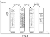
- As shown in
FIG. 1 , when the BWP1 is in an activated status, if the BWP2 is activated, the BWP1 will be deactivated. If the BWP1 is activated, the BWP2 will be deactivated. If the BWP1 is time-expired, it will fall back to a default BWP. - As the switchover of the BWP may cause Radio Frequency (RF) retuning of the terminal, the terminal can receive or transmit a signal in a new BWP upon the completion of the RF retuning. According to solutions in a related art, as long as an activated BWP is switched, it is assumed that the terminal will perform the RF retuning and the terminal does not receive or transmit the signal in the new BWP during the RF retuning. In some cases, data or important signaling that should be received and transmitted cannot be received and transmitted timely, so that the transmission reliability is reduced, and the spectral efficiency is lowered.
- In order to solve the above-mentioned technical problems, embodiments of the disclosure provide a channel transmission method and device, and a computer storage medium.
- A channel transmission method provided by the embodiments of the disclosure includes the following operations.
- A terminal determines transmission time corresponding to a first channel as a first moment. A BWP activated by the terminal presently is a first BWP.
- The terminal receives first control information from a network device. The first control information includes first indication information, and the first indication information is to indicate that a to-be-activated BWP is a second BWP.
- The terminal does not transmit the first channel at the first moment when the first BWP and the second BWP meet a predetermined rule.
- In the embodiment of the disclosure, the method may further include the following operation.
- The terminal transmits the first channel at the first moment when the first BWP and the second BWP do not meet the predetermined rule.
- In the embodiment of the disclosure, the method may further include the following operation.
- The terminal directly activates the second BWP and deactivates the first BWP in response to receiving the first control information when the first BWP and the second BWP do not meet the predetermined rule.
- In the embodiment of the disclosure, the method may further include the following operation.
- The terminal performs RF retuning in response to receiving the first control information when the first BWP and the second BWP meet the predetermined rule, so that an activated BWP is switched from the first BWP to the second BWP.
- In the embodiment of the disclosure, the predetermined rule may include at least one of the followings.
- A central frequency point of the first BWP is not consistent with a central frequency point of the second BWP.
- A bandwidth size of the first BWP is not consistent with a bandwidth size of the second BWP.
- A frequency domain range of the second BWP exceeds a frequency domain range of the second BWP.
- An RF bandwidth capacity of the terminal cannot simultaneously cover the frequency domain range of the first BWP and the frequency domain range of the second BWP.
- In the embodiment of the disclosure, the operation that the terminal determines the transmission time corresponding to the first channel as the first moment may include the following action.
- The terminal determines, as per a configuration or scheduling from the network device, the transmission time corresponding to the first channel as the first moment.
- In the embodiment of the disclosure, the operation that the terminal receives the first control information from the network device may include the following action.
- The terminal receives, at a second moment before the first moment, the first control information from the network device.
- In the embodiment of the disclosure, the first channel may be a Physical Downlink Control Channel (PDCCH), or a Physical Downlink Shared Channel (PDSCH), or a Physical Uplink Control Channel (PUCCH), or a Physical Uplink Shared Channel (PUSCH), or a Physical Random Access Channel (PRACH), or a Channel State Information-Reference Signal (CSI-RS), or a Sounding Reference Signal (SRS).
- In the embodiment of the disclosure, the first control information may be DCI or a Media Access Control Control Element (MAC CE).
- A channel transmission method provided by the embodiments of the disclosure includes the following operation.
- A network device transmits first control information to a terminal. A BWP activated by the terminal presently is a first BWP. The first control information includes first indication information, and the first indication information is to indicate that a to-be-activated BWP is a second BWP. The first control information is used by the terminal to determine that the first BWP and the second BWP meet a predetermined rule, such that the terminal does not transmit a first channel at a first moment.
- In the embodiment of the disclosure, the first control information may be further used by the terminal to determine that the first BWP and the second BWP do not meet the predetermined rule, such that the terminal transmits the first channel at the first moment.
- In the embodiment of the disclosure, the first control information may be further used by the terminal to determine that the first BWP and the second BWP do not meet the predetermined rule, such that the terminal directly activates the second BWP and deactivates the first BWP in response to receiving the first control information.
- In the embodiment of the disclosure, the first control information may be further used by the terminal to determine that the first BWP and the second BWP meet the predetermined rule, such that the terminal performs RF retuning in response to receiving the first control information to switch an activated BWP from the first BWP to the second BWP.
- In the embodiment of the disclosure, the predetermined rule may include at least one of the followings.
- A central frequency point of the first BWP is not consistent with a central frequency point of the second BWP.
- A bandwidth size of the first BWP is not consistent with a bandwidth size of the second BWP.
- A frequency domain range of the second BWP exceeds a frequency domain range of the second BWP.
- An RF bandwidth capacity of the terminal cannot simultaneously cover the frequency domain range of the first BWP and the frequency domain range of the second BWP.
- In the embodiment of the disclosure, the method may further include the following operation.
- The network device configures or schedules the transmission time corresponding to the first channel as the first moment for the terminal.
- In the embodiment of the disclosure, the operation that the network device transmits the first control information to the terminal may include the following action.
- The network device transmits the first control information to the terminal at a second moment before the first moment.
- In the embodiment of the disclosure, the first channel may be a PDCCH, or a PDSCH, or a PUCCH, or a PUSCH, or a PRACH, or a CSI-RS, or an SRS.
- In the embodiment of the disclosure, the first control information may be DCI or an MAC CE.
- A channel transmission device provided by the embodiments of the disclosure includes: a determination unit, a receiving unit and a transmission unit.
- The determination unit is configured to determine transmission time corresponding to a first channel as a first moment. A BWP activated by the terminal presently is a first BWP.
- The receiving unit is configured to receive first control information from a network device. The first control information includes first indication information, and the first indication information is to indicate that a to-be-activated BWP is a second BWP.
- The transmission unit is configured to transmit no first channel at the first moment when the first BWP and the second BWP meet a predetermined rule.
- In the embodiment of the disclosure, the transmission unit may be further configured to transmit the first channel at the first moment when the first BWP and the second BWP do not meet the predetermined rule.
- In the embodiment of the disclosure, the device may further include a first switching unit.
- The first switching unit is configured to directly activate the second BWP and deactivate the first BWP in response to receiving the first control information when the first BWP and the second BWP do not meet the predetermined rule.
- In the embodiment of the disclosure, the device may further include a second switching unit.
- The second switching unit is configured to perform RF retuning in response to receiving the first control information when the first BWP and the second BWP meet the predetermined rule, so that an activated BWP is switched from the first BWP to the second BWP.
- In the embodiment of the disclosure, the predetermined rule may include at least one of the followings.
- A central frequency point of the first BWP is not consistent with a central frequency point of the second BWP.
- A bandwidth size of the first BWP is not consistent with a bandwidth size of the second BWP.
- A frequency domain range of the second BWP exceeds a frequency domain range of the second BWP.
- An RF bandwidth capacity of the terminal cannot simultaneously cover the frequency domain range of the first BWP and the frequency domain range of the second BWP.
- In the embodiment of the disclosure, the determination unit may be configured to determine, as per a configuration or scheduling from the network device, the transmission time corresponding to the first channel as the first moment.
- In the embodiment of the disclosure, the receiving unit may be configured to receive, at a second moment before the first moment, the first control information from the network device.
- In the embodiment of the disclosure, the first channel may be a PDCCH, or a PDSCH, or a PUCCH, or a PUSCH, or a PRACH, or a CSI-RS, or an SRS.
- In the embodiment of the disclosure, the first control information may be DCI or an MAC CE.
- A channel transmission device provided by the embodiments of the disclosure includes a transmitting unit.
- The transmitting unit is configured to transmit first control information to a terminal. A BWP activated by the terminal presently is a first BWP. The first control information includes first indication information, and the first indication information is to indicate that a to-be-activated BWP is a second BWP. The first control information is used by the terminal to determine that the first BWP and the second BWP meet a predetermined rule, such that the terminal does not transmit a first channel at a first moment.
- In the embodiment of the disclosure, the first control information may be further used by the terminal to determine that the first BWP and the second BWP do not meet the predetermined rule, such that the terminal transmits the first channel at the first moment.
- In the embodiment of the disclosure, the first control information may be further used by the terminal to determine that the first BWP and the second BWP do not meet the predetermined rule, such that the terminal directly activates the second BWP and deactivates the first BWP in response to receiving the first control information.
- In the embodiment of the disclosure, the first control information may be further used by the terminal to determine that the first BWP and the second BWP meet the predetermined rule, such that the terminal performs RF retuning in response to receiving the first control information to switch an activated BWP from the first BWP to the second BWP.
- In the embodiment of the disclosure, the predetermined rule may include at least one of the followings.
- A central frequency point of the first BWP is not consistent with a central frequency point of the second BWP.
- A bandwidth size of the first BWP is not consistent with a bandwidth size of the second BWP.
- A frequency domain range of the second BWP exceeds a frequency domain range of the second BWP.
- An RF bandwidth capacity of the terminal cannot simultaneously cover the frequency domain range of the first BWP and the frequency domain range of the second BWP.
- In the embodiment of the disclosure, the device may further include a configuration unit.
- The configuration unit may be configured to configure or schedule the transmission time corresponding to the first channel as the first moment for the terminal.
- In the embodiment of the disclosure, the transmitting unit may be configured to transmit the first control information to the terminal at a second moment before the first moment.
- In the embodiment of the disclosure, the first channel may be a PDCCH, or a PDSCH, or a PUCCH, or a PUSCH, or a PRACH, or a CSI-RS, or an SRS.
- In the embodiment of the disclosure, the first control information may be DCI or an MAC CE.
- A computer storage medium provided by the embodiments of the disclosure stores computer executable instructions which, when being executed by a processor, cause the processor to implement the above-mentioned channel transmission method.
- In the technical solutions provided by the embodiments of the disclosure, a terminal determines transmission time corresponding to a first channel as a first moment, a BWP activated by the terminal presently is a first BWP; the terminal receives first control information from a network device, the first control information includes first indication information, and the first indication information is to indicate that a to-be-activated BWP is a second BWP; and the terminal does not transmit the first channel at the first moment if the first BWP and the second BWP meet a predetermined rule. With the technical solutions in the embodiments of the disclosure, when the terminal switches from the first BWP to the second BWP, whether the terminal needs to perform RF retuning is determined according to the predetermined rule, thereby determining whether the terminal may transmit a signal within a new BWP in a BWP switching process. Therefore, an unnecessary BWP switching interval is prevented, and the transmission reliability and the spectral efficiency are improved.
- The accompanying drawings are described here to provide a further understanding of the disclosure, and form a part of the disclosure. The schematic embodiments of the disclosure and description thereof are used to explain the disclosure, and do not intended to limit the disclosure. In the drawings:
-
FIG. 1 is a schematic diagram showing that only one BWP can be in an activated status. -
FIG. 2 is a first flowchart schematic diagram of a channel transmission method according to an embodiment of the disclosure. -
FIG. 3 is a second flowchart schematic diagram of a channel transmission method according to an embodiment of the disclosure. -
FIG. 4 is a schematic diagram showing that a BWP1 is not consistent with a BWP2 in central frequency point and bandwidth size, and a terminal needs to switch a BWP with RF retuning, according to an embodiment of the disclosure. -
FIG. 5 is a schematic diagram showing that a BWP1 is consistent with a BWP2 in central frequency point and bandwidth size, and a terminal can switch a BWP without RF retuning, according to an embodiment of the disclosure. -
FIG. 6 is a schematic diagram showing that a frequency range of a BWP2 is within a frequency range of a BWP1, and a terminal can switch a BWP without RF retuning, according to an embodiment of the disclosure. -
FIG. 7 is a first structural schematic diagram of a channel transmission device according to an embodiment of the disclosure. -
FIG. 8 is a second structural schematic diagram of a channel transmission device according to an embodiment of the disclosure. -
FIG. 9 is a structural schematic diagram of a computer device according to an embodiment of the disclosure. - For making the characteristics and technical contents of the embodiments of the disclosure understood in more detail, implementation of the embodiments of the disclosure will be described below in combination with the drawings in detail. The drawings are only adopted for description as references and not intended to limit the embodiments of the disclosure.
-
FIG. 2 is a first flowchart schematic diagram of a channel transmission method according to an embodiment of the disclosure. As shown inFIG. 2 , the channel transmission method includes the following operations. - At
block 201, a terminal determines transmission time corresponding to a first channel as a first moment, a BWP activated by the terminal presently being a first BWP. - In the embodiment of the disclosure, the terminal may be any device capable of communicating with a network such as a mobile phone, a tablet computer, a notebook and a desktop computer.
- In the embodiment of the disclosure, the network device may be a base station, such as a gNB in a 5G system.
- In an implementation, the terminal determines, as per a configuration or scheduling from the network device, the transmission time corresponding to the first channel as the first moment. That is, according to the configuration or the scheduling from the network device, the terminal should transmit the first channel at the first moment.
- At
block 202, the terminal receives first control information from a network device. The first control information includes first indication information, and the first indication information is used for indicating that a to-be-activated BWP is a second BWP. - In an implementation, the terminal receives, at a second moment before the first moment, the first control information transmitted by the network device. For example, the terminal receives the first control information at a t1 moment, and is anticipated to transmit the first channel at a t2 moment (later than the t1 moment). At this time, if RF retuning needs to be performed for switchover between the first BWP and the second BWP, the first channel may not be transmitted at the t2 moment. If the RF retuning does not need to be performed for the switchover between the first BWP and the second BWP, the second BWP may be directly utilized to transmit a message in response to receiving the first control information, and in such a case, the first channel may be transmitted at the t2 moment.
- The first channel is not limited in the embodiment of the disclosure. The first channel may be any type of channel or signal, for example, a PDCCH, or a PDSCH, or a PUCCH, or a PUSCH, or a PRACH, or a CSI-RS, or an SRS.
- In an implementation, the first control information is DCI or an MAC CE.
- At
block 203, the terminal does not transmit the first channel at the first moment upon a condition that the first BWP and the second BWP meet a predetermined rule. - In the embodiment of the disclosure, the terminal transmits the first channel at the first moment if the first BWP and the second BWP do not meet the predetermined rule.
- In the embodiment of the disclosure, the predetermined rule includes at least one of the followings.
- A central frequency point of the first BWP is not consistent with a central frequency point of the second BWP.
- A bandwidth size of the first BWP is not consistent with a bandwidth size of the second BWP.
- A frequency domain range of the second BWP exceeds a frequency domain range of the second BWP.
- An RF bandwidth capacity of the terminal cannot simultaneously cover the frequency domain range of the first BWP and the frequency domain range of the second BWP.
- In the embodiment of the disclosure, if the first BWP and the second BWP only have different numerologies and are consistent in the central frequency point and the bandwidth size, or the frequency domain range of the second BWP is within the frequency domain range of the first BWP, the terminal does not need to perform the RF retuning. Upon this, 1) the terminal directly activates the second BWP and deactivates the first BWP in response to receiving the first control information if the first BWP and the second BWP do not meet the predetermined rule; and 2) the terminal performs the RF retuning in response to receiving the first control information if the first BWP and the second BWP meet the predetermined rule, so that an activated BWP is switched from the first BWP to the second BWP.
-
FIG. 3 is a second flowchart schematic diagram of a channel transmission method according to an embodiment of the disclosure. As shown inFIG. 3 , the channel transmission method includes the following operations. - At
block 301, a network device transmits first control information to a terminal. A BWP activated by the terminal presently is a first BWP. The first control information includes first indication information, and the first indication information is used for indicating that a to-be-activated BWP is a second BWP. The first control information is used by the terminal to determine that the first BWP and the second BWP meet a predetermined rule, such that the terminal does not transmit a first channel at a first moment. - In an implementation, the first control information is further used by the terminal to determine that the first BWP and the second BWP do not meet the predetermined rule, such that the terminal transmits the first channel at the first moment.
- In an implementation, the first control information is further used by the terminal to determine that the first BWP and the second BWP do not meet the predetermined rule, such that the terminal directly activates the second BWP and deactivates the first BWP in response to receiving the first control information.
- In an implementation, the first control information is further used by the terminal to determine that the first BWP and the second BWP meet the predetermined rule, such that the terminal performs RF retuning in response to receiving the first control information, to switch an activated BWP from the first BWP to the second BWP.
- In an implementation, the predetermined rule includes at least one of the followings.
- A central frequency point of the first BWP is not consistent with a central frequency point of the second BWP.
- A bandwidth size of the first BWP is not consistent with a bandwidth size of the second BWP.
- A frequency domain range of the second BWP exceeds a frequency domain range of the second BWP.
- An RF bandwidth capacity of the terminal cannot simultaneously cover the frequency domain range of the first BWP and the frequency domain range of the second BWP.
- In an implementation, the network device configures or schedules the transmission time corresponding to the first channel as the first moment for the terminal.
- In an implementation, the network device transmits the first control information to the terminal at a second moment before the first moment.
- In an implementation, the first channel is a PDCCH, or a PDSCH, or a PUCCH, or a PUSCH, or a PRACH, or a CSI-RS, or an SRS.
- In an implementation, the first control information is DCI or an MAC CE.
- The technical solutions of the disclosure are further described below in combination with specific application examples.
- Example 1: a BWP1 is not consistent with a BWP2 in central frequency point and bandwidth size, and a terminal needs to switch a BWP with RF retuning
- As shown in
FIG. 4 , the BWP1 is not consistent with the BWP2 in central frequency point and bandwidth size. The terminal needs to perform RF retuning in response to receiving DCI (first control information) for activating the BWP2 and cannot start to use the BWP2 until the completion of the RF tuning. During the RF tuning, the terminal cannot transmit a channel on the BWP2. - Example 2: a BWP1 is consistent with a BWP2 in central frequency point and bandwidth size, and a terminal may switch a BWP without RF retuning
- As shown in
FIG. 5 , the BWP1 is consistent with the BWP2 in central frequency point and bandwidth size. The terminal does not need to perform the RF retuning, and may immediately start to use the BWP2 to transmit the first channel in response to receiving DCI (first control information) for activating the BWP2. - According to the technical solutions of the embodiments of the disclosure, when the terminal switches from the BWP1 to the BWP2, whether the terminal needs to perform the RF retuning is determined according to the predetermined rule, thereby determining whether the terminal may transmit a signal within a new BWP (i.e., the BWP2) in a BWP switching process. Therefore, an unnecessary BWP switching interval is prevented, and the transmission reliability and the spectral efficiency are improved.
- Example 3: a frequency range of a BWP2 is within a frequency range of a BWP1, and a terminal may switch a BWP without RF retuning
- As shown in
FIG. 6 , the frequency range of the BWP2 is within the frequency range of the BWP1. The terminal does not need to perform the RF retuning, and may immediately start to use the BWP2 to transmit the first channel in response to receiving DCI (first control information) for activating the BWP2. - According to the technical solutions of the embodiments of the disclosure, when the terminal switches from the BWP1 to the BWP2, whether the terminal needs to perform the RF retuning is determined according to the predetermined rule, thereby determining whether the terminal may transmit a signal within a new BWP (i.e., the BWP2) in a BWP switching process. Therefore, an unnecessary BWP switching interval is prevented, and the transmission reliability and the spectral efficiency are improved.
-
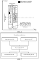
FIG. 7 is a first structural schematic diagram of a channel transmission device according to an embodiment of the disclosure. As shown inFIG. 7 , the channel transmission device includes: adetermination unit 701, a receivingunit 702 and atransmission unit 703. - The
determination unit 701 is configured to determine transmission time corresponding to a first channel as a first moment. A BWP activated by the terminal presently is a first BWP. - The receiving
unit 702 is configured to receive first control information from a network device. The first control information includes first indication information, and the first indication information is used for indicating that a to-be-activated BWP is a second BWP. - The
transmission unit 703 is configured to not transmit the first channel at the first moment upon a condition that the first BWP and the second BWP meet a predetermined rule. - In an implementation, the
transmission unit 703 is further configured to transmit the first channel at the first moment upon a condition that the first BWP and the second BWP do not meet the predetermined rule. - In an implementation, the device further includes a
first switching unit 704. - The
first switching unit 704 is configured to, if the first BWP and the second BWP do not meet the predetermined rule, directly activate the second BWP and deactivate the first BWP in response to receiving the first control information. - In an implementation, the device further includes a
second switching unit 705. - The
second switching unit 705 is configured to, if the first BWP and the second BWP meet the predetermined rule, perform RF retuning in response to receiving the first control information, so that an activated BWP is switched from the first BWP to the second BWP. - In an implementation, the predetermined rule includes at least one of the followings.
- A central frequency point of the first BWP is not consistent with a central frequency point of the second BWP.
- A bandwidth size of the first BWP is not consistent with a bandwidth size of the second BWP.
- A frequency domain range of the second BWP exceeds a frequency domain range of the second BWP.
- An RF bandwidth capacity of the terminal cannot simultaneously cover the frequency domain range of the first BWP and the frequency domain range of the second BWP.
- In an implementation, the
determination unit 701 is configured to determine, as per a configuration or scheduling from the network device, the transmission time corresponding to the first channel as the first moment. - In an implementation, the receiving
unit 702 is configured to receive, at a second moment before the first moment, the first control information transmitted by the network device. - In an implementation, the first channel is a PDCCH, or a PDSCH, or a PUCCH, or a PUSCH, or a PRACH, or a CSI-RS, or an SRS.
- In an implementation, the first control information is DCI or an MAC CE.
- Those skilled in the art will appreciate that functions implemented by each unit in the resource transmission device shown in
FIG. 7 may be understood with reference to related descriptions about the channel transmission method. The functions of each unit in the channel transmission device shown inFIG. 7 may be implemented through a program running in a processor, and may also be implemented through a specific logical circuit. -
FIG. 8 is a second structural schematic diagram of a channel transmission device according to an embodiment of the disclosure. As shown inFIG. 8 , the channel transmission device includes a transmittingunit 801. - The transmitting
unit 801 is configured to transmit first control information to a terminal. A BWP activated by the terminal presently is a first BWP. The first control information includes first indication information, and the first indication information is used for indicating that a to-be-activated BWP is a second BWP. The first control information is used by the terminal to determine that the first BWP and the second BWP meet a predetermined rule, such that the terminal does not transmit a first channel at a first moment. - In an implementation, the first control information is further used by the terminal to determine that the first BWP and the second BWP do not meet the predetermined rule, such that the terminal transmits the first channel at the first moment.
- In an implementation, the first control information is further used by the terminal to determine that the first BWP and the second BWP do not meet the predetermined rule, such that the terminal directly activates the second BWP and deactivates the first BWP in response to receiving the first control information.
- In an implementation, the first control information is further used by the terminal to determine that the first BWP and the second BWP meet the predetermined rule, such that the terminal performs RF retuning in response to receiving the first control information, to switch an activated BWP from the first BWP to the second BWP.
- In an implementation, the predetermined rule includes at least one of the followings.
- A central frequency point of the first BWP is not consistent with a central frequency point of the second BWP.
- A bandwidth size of the first BWP is not consistent with a bandwidth size of the second BWP.
- A frequency domain range of the second BWP exceeds a frequency domain range of the second BWP.
- An RF bandwidth capacity of the terminal cannot simultaneously cover the frequency domain range of the first BWP and the frequency domain range of the second BWP.
- In an implementation, the device further includes a configuration unit 802.
- The configuration unit 802 is configured to configure or schedule the transmission time corresponding to the first channel as the first moment for the terminal.
- In an implementation, the transmitting
unit 801 is configured to transmit the first control information to the terminal at a second moment before the first moment. - In an implementation, the first channel is a PDCCH, or a PDSCH, or a PUCCH, or a PUSCH, or a PRACH, or a CSI-RS, or an SRS.
- In an implementation, the first control information is DCI or an MAC CE.
- Those skilled in the art will appreciate that functions implemented by each unit in the resource transmission device shown in
FIG. 8 may be understood with reference to related descriptions about the channel transmission method. The functions of each unit in the channel transmission device shown inFIG. 8 may be implemented through a program running in a processor, and may also be implemented through a specific logical circuit. - When being implemented in form of software functional module and sold or used as an independent product, the channel transmission device in the embodiments of the disclosure may also be stored in a computer-readable storage medium. Based on such an understanding, the technical solutions in the embodiments of the disclosure substantially or parts making contributions to the conventional art may be embodied in form of software product, and the computer software product is stored in a storage medium, including a plurality of instructions used to enable a computer device (which may be a personal computer, a server, a network device or the like) to execute all or part of the method in each embodiment of the disclosure. The storage medium includes: various media capable of storing program codes such as a U disk, a mobile hard disk, a Read Only Memory (ROM), a magnetic disk or an optical disk. Therefore, the embodiments of the disclosure are not limited to any specific hardware and software combination.
- Correspondingly, the embodiments of the disclosure also provide a computer storage medium having stored therein computer-executable instructions that, when being executed by a processor, cause the processor to implement the channel transmission method in the embodiments of the disclosure.
-
FIG. 9 is a structural schematic diagram of a computer device according to an embodiment of the disclosure. The computer device may be a terminal, and may also be a network device. As shown inFIG. 9 , thecomputer device 100 may include one or more (only one is illustrated in the figure) processors 1002 (theprocessor 1002 may include, but not limited to, a processing device such as a Micro Control Unit (MCU) or a Field Programmable Gate Array (FPGA)), amemory 1004 for storing data and atransmission device 1006 configured for a communication function. Those of ordinary skill in the art will appreciate that the structure shown inFIG. 9 is only schematic and not intended to limit the structure of the electronic device. For example, thecomputer device 100 may further include components more or fewer than the components shown inFIG. 9 or has a configuration different from that shown inFIG. 9 . - The
memory 1004 may be configured to store a software program of application software and a module, for example, a program instruction/module corresponding to a method in the embodiments of the disclosure. Theprocessor 1002 runs the software program and module stored in thememory 1004, thereby executing various functional applications and data processing, namely implementing the above-mentioned method. Thememory 1004 may include a high-speed random access memory and may also include a non-volatile memory, for example, one or more magnetic storage devices, flash memories or other non-volatile solid-state memories. In some examples, thememory 1004 may further include a memory arranged remotely relative to theprocessor 1002 and the remote memory may be connected to thecomputer device 100 through a network. An example of the network includes, but not limited to, the Internet, an intranet, a local area network, a mobile communication network or a combination thereof. - The
transmission device 1006 is configured to receive or transmit data through a network. A specific example of the network may include a wireless network provided by a communication provider of thecomputer device 100. In an example, thetransmission device 1006 includes a Network Interface Controller (NIC), which may be connected with another network device through a base station, thereby communicating with the Internet. In an example, thetransmission device 1006 may be a Radio Frequency (RF) module, configured to communicate with the Internet in a wireless manner. - The technical solutions recited in the embodiments of the disclosure may be freely combined without conflicts.
- In some embodiments provided by the disclosure, it is to be understood that the disclosed method and intelligent device may be implemented in another manner. The device embodiment described above is only schematic, and for example, division of the units is only logic function division, and other division manners may be adopted during practical implementation. For example, multiple units or components may be combined or integrated into another system, or some characteristics may be neglected or not executed. In addition, coupling or direct coupling or communication connection between each displayed or discussed component may be indirect coupling or communication connection, implemented through some interfaces, of the device or the units, and may be electrical and mechanical or adopt other forms.
- The units described as separate parts may or may not be physically separated, and parts displayed as units may or may not be physical units, and namely may be located in the same place, or may also be distributed to multiple network units. Part of all of the units may be selected according to a practical requirement to achieve the purposes of the solutions in the embodiments.
- In addition, each functional unit in each embodiment of the disclosure may be integrated into a second processing unit, each unit may also serve as an independent unit and two or more than two units may also be integrated into a unit. The integrated unit may be implemented in a hardware form and may also be implemented in form of hardware and software functional unit.
- Described above are only specific embodiments of the disclosure and not intended to limit the scope of protection of the disclosure. Any variations or replacements apparent to those skilled in the art within the technical scope disclosed by the disclosure shall fall within the scope of protection of the disclosure.
Claims (37)
- A channel transmission method, comprising:determining, by a terminal, transmission time corresponding to a first channel as a first moment, wherein a Band Width Part (BWP) activated by the terminal presently is a first BWP;receiving, by the terminal, first control information from a network device, wherein the first control information comprises first indication information, and the first indication information is to indicate that a to-be-activated BWP is a second BWP; andtransmitting, by the terminal, no first channel at the first moment when the first BWP and the second BWP meet a predetermined rule.
- The method of claim 1, further comprising:
transmitting, by the terminal, the first channel at the first moment when the first BWP and the second BWP do not meet the predetermined rule. - The method of claim 2, further comprising:
directly activating, by the terminal, the second BWP and deactivating the first BWP in response to receiving the first control information when the first BWP and the second BWP do not meet the predetermined rule. - The method of any one of claims 1 to 3, further comprising:
performing, by the terminal, Radio Frequency (RF) retuning in response to receiving the first control information when the first BWP and the second BWP meet the predetermined rule, so that an activated BWP is switched from the first BWP to the second BWP. - The method of any one of claims 1 to 4, wherein the predetermined rule comprises at least one of the followings:a central frequency point of the first BWP is not consistent with a central frequency point of the second BWP;a bandwidth size of the first BWP is not consistent with a bandwidth size of the second BWP;a frequency domain range of the second BWP exceeds a frequency domain range of the second BWP; oran RF bandwidth capacity of the terminal cannot simultaneously cover the frequency domain range of the first BWP and the frequency domain range of the second BWP.
- The method of any one of claims 1 to 5, wherein determining, by the terminal, the transmission time corresponding to the first channel as the first moment comprises:
determining, by the terminal, as per a configuration or scheduling from the network device, the transmission time corresponding to the first channel as the first moment. - The method of any one of claims 1 to 6, wherein receiving, by the terminal, the first control information from the network device comprises:
receiving, by the terminal, at a second moment before the first moment, the first control information from the network device. - The method of any one of claims 1 to 7, wherein the first channel is a Physical Downlink Control Channel (PDCCH), or a Physical Downlink Shared Channel (PDSCH), or a Physical Uplink Control Channel (PUCCH), or a Physical Uplink Shared Channel (PUSCH), or a Physical Random Access Channel (PRACH), or a Channel State Information-Reference Signal (CSI-RS), or a Sounding Reference Signal (SRS).
- The method of any one of claims 1 to 8, wherein the first control information is Downlink Control Information (DCI) or a Media Access Control Control Element (MAC CE).
- A channel transmission method, comprising:
transmitting, by a network device, first control information to a terminal, wherein a Band Width Part (BWP) activated by the terminal presently is a first BWP, the first control information comprises first indication information, the first indication information is to indicate that a to-be-activated BWP is a second BWP, and wherein the first control information is used by the terminal to determine that the first BWP and the second BWP meet a predetermined rule, such that the terminal does not transmit a first channel at a first moment. - The method of claim 10, wherein the first control information is further used by the terminal to determine that the first BWP and the second BWP do not meet the predetermined rule, such that the terminal transmits the first channel at the first moment.
- The method of claim 11, wherein the first control information is further used by the terminal to determine that the first BWP and the second BWP do not meet the predetermined rule, such that the terminal directly activates the second BWP and deactivates the first BWP in response to receiving the first control information.
- The method of any one of claims 10 to 12, wherein the first control information is further used by the terminal to determine that the first BWP and the second BWP meet the predetermined rule, such that the terminal performs Radio Frequency (RF) retuning in response to receiving the first control information to switch an activated BWP from the first BWP to the second BWP.
- The method of any one of claims 10 to 13, wherein the predetermined rule comprises at least one of the followings:a central frequency point of the first BWP is not consistent with a central frequency point of the second BWP;a bandwidth size of the first BWP is not consistent with a bandwidth size of the second BWP;a frequency domain range of the second BWP exceeds a frequency domain range of the second BWP; oran RF bandwidth capacity of the terminal cannot simultaneously cover the frequency domain range of the first BWP and the frequency domain range of the second BWP.
- The method of any one of claims 10 to 14, further comprising:
configuring or scheduling, by the network device, the transmission time corresponding to the first channel as the first moment for the terminal. - The method of any one of claims 10 to 15, wherein transmitting, by the network device, the first control information to the terminal comprises:
transmitting, by the network device, the first control information to the terminal at a second moment before the first moment. - The method of any one of claims 10 to 16, wherein the first channel is a Physical Downlink Control Channel (PDCCH), or a Physical Downlink Shared Channel (PDSCH), or a Physical Uplink Control Channel (PUCCH), or a Physical Uplink Shared Channel (PUSCH), or a Physical Random Access Channel (PRACH), or a Channel State Information-Reference Signal (CSI-RS), or a Sounding Reference Signal (SRS).
- The method of any one of claims 10 to 17, wherein the first control information is Downlink Control Information (DCI) or a Media Access Control Control Element (MAC CE).
- A channel transmission device, comprising:a determination unit, configured to determine transmission time corresponding to a first channel as a first moment, wherein a Band Width Part (BWP) activated by a terminal presently is a first BWP;a receiving unit, configured to receive first control information from a network device, wherein the first control information comprises first indication information, and the first indication information is to indicate that a to-be-activated BWP is a second BWP; anda transmission unit, configured to transmit no first channel at the first moment when the first BWP and the second BWP meet a predetermined rule.
- The device of claim 19, wherein the transmission unit is further configured to transmit the first channel at the first moment when the first BWP and the second BWP do not meet the predetermined rule.
- The device of claim 20, further comprising:
a first switching unit, configured to directly activate the second BWP and deactivate the first BWP in response to receiving the first control information when the first BWP and the second BWP do not meet the predetermined rule. - The device of any one of claims 19 to 21, further comprising:
a second switching unit, configured to perform Radio Frequency (RF) retuning in response to receiving the first control information when the first BWP and the second BWP meet the predetermined rule, so that an activated BWP is switched from the first BWP to the second BWP. - The device of any one of claims 19 to 22, wherein the predetermined rule comprises at least one of the followings:a central frequency point of the first BWP is not consistent with a central frequency point of the second BWP;a bandwidth size of the first BWP is not consistent with a bandwidth size of the second BWP;a frequency domain range of the second BWP exceeds a frequency domain range of the second BWP; oran RF bandwidth capacity of the terminal cannot simultaneously cover the frequency domain range of the first BWP and the frequency domain range of the second BWP.
- The device of any one of claims 19 to 23, wherein the determination unit is configured to determine, as per a configuration or scheduling from the network device, the transmission time corresponding to the first channel as the first moment.
- The device of any one of claims 19 to 24, wherein the receiving unit is configured to receive, at a second moment before the first moment, the first control information from the network device.
- The device of any one of claims 19 to 25, wherein the first channel is a Physical Downlink Control Channel (PDCCH), or a Physical Downlink Shared Channel (PDSCH), or a Physical Uplink Control Channel (PUCCH), or a Physical Uplink Shared Channel (PUSCH), or a Physical Random Access Channel (PRACH), or a Channel State Information-Reference Signal (CSI-RS), or a Sounding Reference Signal (SRS).
- The device of any one of claims 19 to 26, wherein the first control information is Downlink Control Information (DCI) or a Media Access Control Control Element (MAC CE).
- A channel transmission device, comprising:
a transmitting unit, configured to transmit first control information to a terminal, wherein a Band Width Part (BWP) activated by the terminal presently is a first BWP, the first control information comprises first indication information, the first indication information is to indicate that a to-be-activated BWP is a second BWP, and wherein the first control information is used by the terminal to determine that the first BWP and the second BWP meet a predetermined rule, such that the terminal does not transmit a first channel at a first moment. - The device of claim 28, wherein the first control information is further used by the terminal to determine that the first BWP and the second BWP do not meet the predetermined rule, such that the terminal transmits the first channel at the first moment.
- The device of claim 29, wherein the first control information is further used by the terminal to determine that the first BWP and the second BWP do not meet the predetermined rule, such that the terminal directly activates the second BWP and deactivates the first BWP in response to receiving the first control information.
- The device of any one of claims 28 to 30, wherein the first control information is further used by the terminal to determine that the first BWP and the second BWP meet the predetermined rule, such that the terminal performs Radio Frequency (RF) retuning in response to receiving the first control information to switch an activated BWP from the first BWP to the second BWP.
- The device of any one of claims 28 to 31, wherein the predetermined rule comprises at least one of the followings:a central frequency point of the first BWP is not consistent with a central frequency point of the second BWP;a bandwidth size of the first BWP is not consistent with a bandwidth size of the second BWP;a frequency domain range of the second BWP exceeds a frequency domain range of the second BWP; oran RF bandwidth capacity of the terminal cannot simultaneously cover the frequency domain range of the first BWP and the frequency domain range of the second BWP.
- The device of any one of claims 28 to 32, further comprising:
a configuration unit, configured to configure or schedule the transmission time corresponding to the first channel as the first moment for the terminal. - The device of any one of claims 28 to 33, wherein the transmitting unit is configured to transmit the first control information to the terminal at a second moment before the first moment.
- The device of any one of claims 28 to 34, wherein the first channel is a Physical Downlink Control Channel (PDCCH), or a Physical Downlink Shared Channel (PDSCH), or a Physical Uplink Control Channel (PUCCH), or a Physical Uplink Shared Channel (PUSCH), or a Physical Random Access Channel (PRACH), or a Channel State Information-Reference Signal (CSI-RS), or a Sounding Reference Signal (SRS).
- The device of any one of claims 28 to 35, wherein the first control information is Downlink Control Information (DCI) or a Media Access Control Control Element (MAC CE).
- A computer storage medium having stored therein computer executable instructions which, when being executed by a processor, cause the processor to implement steps of the method of any one of claims 1 to 9, or steps of the method of any one of claims 10 to 18.
Applications Claiming Priority (1)
| Application Number | Priority Date | Filing Date | Title |
|---|---|---|---|
| PCT/CN2018/075865 WO2019153206A1 (en) | 2018-02-08 | 2018-02-08 | Channel transmission method and device, and computer storage medium |
Publications (3)
| Publication Number | Publication Date |
|---|---|
| EP3749015A4 EP3749015A4 (en) | 2020-12-09 |
| EP3749015A1 true EP3749015A1 (en) | 2020-12-09 |
| EP3749015B1 EP3749015B1 (en) | 2024-07-24 |
Family
ID=67548685
Family Applications (1)
| Application Number | Title | Priority Date | Filing Date |
|---|---|---|---|
| EP18904666.7A Active EP3749015B1 (en) | 2018-02-08 | 2018-02-08 | Channel transmission method and device, and computer storage medium |
Country Status (7)
| Country | Link |
|---|---|
| US (1) | US11356230B2 (en) |
| EP (1) | EP3749015B1 (en) |
| JP (1) | JP2021518065A (en) |
| KR (1) | KR20200118188A (en) |
| CN (1) | CN111684836A (en) |
| AU (1) | AU2018407193A1 (en) |
| WO (1) | WO2019153206A1 (en) |
Families Citing this family (2)
| Publication number | Priority date | Publication date | Assignee | Title |
|---|---|---|---|---|
| EP3528538B1 (en) | 2018-02-15 | 2021-08-18 | Panasonic Intellectual Property Corporation of America | Bandwidth part operation during handover procedure |
| CN114586450B (en) * | 2022-01-20 | 2025-08-12 | 北京小米移动软件有限公司 | Method, device, communication equipment and storage medium for switching BWP |
Family Cites Families (4)
| Publication number | Priority date | Publication date | Assignee | Title |
|---|---|---|---|---|
| ES2347747B1 (en) * | 2008-08-06 | 2011-09-07 | Vodafone España, S.A | PROCEDURE AND SYSTEM TO ACCESS TRANSPORT CAPACITY IN SHARED RADIO ACCESS NETWORKS. |
| KR20170134238A (en) * | 2016-05-27 | 2017-12-06 | 주식회사 아이티엘 | Method and apparatus for transmitting and receiving control channel and data channel for nr system |
| BR112020002078A2 (en) * | 2017-08-02 | 2020-07-28 | Ntt Docomo, Inc. | user terminal, base station and radio communication method |
| EP3442304B1 (en) * | 2017-08-07 | 2020-09-23 | HTC Corporation | Method of handling radio link failure and related communication device |
-
2018
- 2018-02-08 AU AU2018407193A patent/AU2018407193A1/en not_active Abandoned
- 2018-02-08 KR KR1020207025946A patent/KR20200118188A/en not_active Withdrawn
- 2018-02-08 WO PCT/CN2018/075865 patent/WO2019153206A1/en not_active Ceased
- 2018-02-08 CN CN201880088721.9A patent/CN111684836A/en active Pending
- 2018-02-08 JP JP2020542738A patent/JP2021518065A/en not_active Withdrawn
- 2018-02-08 EP EP18904666.7A patent/EP3749015B1/en active Active
-
2020
- 2020-08-05 US US16/985,378 patent/US11356230B2/en active Active
Also Published As
| Publication number | Publication date |
|---|---|
| CN111684836A (en) | 2020-09-18 |
| JP2021518065A (en) | 2021-07-29 |
| US20200366453A1 (en) | 2020-11-19 |
| EP3749015A4 (en) | 2020-12-09 |
| AU2018407193A1 (en) | 2020-10-01 |
| US11356230B2 (en) | 2022-06-07 |
| KR20200118188A (en) | 2020-10-14 |
| EP3749015B1 (en) | 2024-07-24 |
| WO2019153206A1 (en) | 2019-08-15 |
Similar Documents
| Publication | Publication Date | Title |
|---|---|---|
| EP3826410B1 (en) | Resource configuration method and device, and computer storage medium | |
| US11589266B2 (en) | Resource configuration method and device, and computer storage medium | |
| US11503578B2 (en) | Resource configuration method and device, and computer storage medium | |
| US20200329483A1 (en) | Method and apparatus for determining transmission direction and transmission channel and computer storage medium | |
| US11356230B2 (en) | Channel transmission methods and device | |
| JP2020513174A5 (en) | ||
| US11539496B2 (en) | Resource configuration method and device, and computer storage medium | |
| EP3734871A1 (en) | Time-domain resource determination method and apparatus, and computer storage medium | |
| JP2021516893A (en) | Resource configuration method and equipment, computer storage medium | |
| US20240008016A1 (en) | Communication method and apparatus | |
| US12432746B2 (en) | Apparatus and method of communication of same | |
| US20200374095A1 (en) | Resource configuration method and device, and computer storage medium | |
| US11284319B2 (en) | Method for activating and deactivating cell, terminal equipment and computer storage medium |
Legal Events
| Date | Code | Title | Description |
|---|---|---|---|
| STAA | Information on the status of an ep patent application or granted ep patent |
Free format text: STATUS: THE INTERNATIONAL PUBLICATION HAS BEEN MADE |
|
| PUAI | Public reference made under article 153(3) epc to a published international application that has entered the european phase |
Free format text: ORIGINAL CODE: 0009012 |
|
| STAA | Information on the status of an ep patent application or granted ep patent |
Free format text: STATUS: REQUEST FOR EXAMINATION WAS MADE |
|
| 17P | Request for examination filed |
Effective date: 20200831 |
|
| A4 | Supplementary search report drawn up and despatched |
Effective date: 20201110 |
|
| AK | Designated contracting states |
Kind code of ref document: A1 Designated state(s): AL AT BE BG CH CY CZ DE DK EE ES FI FR GB GR HR HU IE IS IT LI LT LU LV MC MK MT NL NO PL PT RO RS SE SI SK SM TR |
|
| AX | Request for extension of the european patent |
Extension state: BA ME |
|
| DAV | Request for validation of the european patent (deleted) | ||
| DAX | Request for extension of the european patent (deleted) | ||
| STAA | Information on the status of an ep patent application or granted ep patent |
Free format text: STATUS: EXAMINATION IS IN PROGRESS |
|
| 17Q | First examination report despatched |
Effective date: 20220117 |
|
| GRAP | Despatch of communication of intention to grant a patent |
Free format text: ORIGINAL CODE: EPIDOSNIGR1 |
|
| STAA | Information on the status of an ep patent application or granted ep patent |
Free format text: STATUS: GRANT OF PATENT IS INTENDED |
|
| INTG | Intention to grant announced |
Effective date: 20240216 |
|
| GRAS | Grant fee paid |
Free format text: ORIGINAL CODE: EPIDOSNIGR3 |
|
| GRAA | (expected) grant |
Free format text: ORIGINAL CODE: 0009210 |
|
| STAA | Information on the status of an ep patent application or granted ep patent |
Free format text: STATUS: THE PATENT HAS BEEN GRANTED |
|
| AK | Designated contracting states |
Kind code of ref document: B1 Designated state(s): AL AT BE BG CH CY CZ DE DK EE ES FI FR GB GR HR HU IE IS IT LI LT LU LV MC MK MT NL NO PL PT RO RS SE SI SK SM TR |
|
| REG | Reference to a national code |
Ref country code: GB Ref legal event code: FG4D |
|
| REG | Reference to a national code |
Ref country code: CH Ref legal event code: EP |
|
| REG | Reference to a national code |
Ref country code: IE Ref legal event code: FG4D Ref country code: DE Ref legal event code: R096 Ref document number: 602018072322 Country of ref document: DE |
|
| P01 | Opt-out of the competence of the unified patent court (upc) registered |
Free format text: CASE NUMBER: APP_49580/2024 Effective date: 20240902 |
|
| REG | Reference to a national code |
Ref country code: LT Ref legal event code: MG9D |
|
| REG | Reference to a national code |
Ref country code: NL Ref legal event code: MP Effective date: 20240724 |
|
| PG25 | Lapsed in a contracting state [announced via postgrant information from national office to epo] |
Ref country code: PT Free format text: LAPSE BECAUSE OF FAILURE TO SUBMIT A TRANSLATION OF THE DESCRIPTION OR TO PAY THE FEE WITHIN THE PRESCRIBED TIME-LIMIT Effective date: 20241125 |
|
| REG | Reference to a national code |
Ref country code: AT Ref legal event code: MK05 Ref document number: 1707432 Country of ref document: AT Kind code of ref document: T Effective date: 20240724 |
|
| PG25 | Lapsed in a contracting state [announced via postgrant information from national office to epo] |
Ref country code: NL Free format text: LAPSE BECAUSE OF FAILURE TO SUBMIT A TRANSLATION OF THE DESCRIPTION OR TO PAY THE FEE WITHIN THE PRESCRIBED TIME-LIMIT Effective date: 20240724 |
|
| PG25 | Lapsed in a contracting state [announced via postgrant information from national office to epo] |
Ref country code: PT Free format text: LAPSE BECAUSE OF FAILURE TO SUBMIT A TRANSLATION OF THE DESCRIPTION OR TO PAY THE FEE WITHIN THE PRESCRIBED TIME-LIMIT Effective date: 20241125 Ref country code: NL Free format text: LAPSE BECAUSE OF FAILURE TO SUBMIT A TRANSLATION OF THE DESCRIPTION OR TO PAY THE FEE WITHIN THE PRESCRIBED TIME-LIMIT Effective date: 20240724 |
|
| PG25 | Lapsed in a contracting state [announced via postgrant information from national office to epo] |
Ref country code: NO Free format text: LAPSE BECAUSE OF FAILURE TO SUBMIT A TRANSLATION OF THE DESCRIPTION OR TO PAY THE FEE WITHIN THE PRESCRIBED TIME-LIMIT Effective date: 20241024 |
|
| PG25 | Lapsed in a contracting state [announced via postgrant information from national office to epo] |
Ref country code: GR Free format text: LAPSE BECAUSE OF FAILURE TO SUBMIT A TRANSLATION OF THE DESCRIPTION OR TO PAY THE FEE WITHIN THE PRESCRIBED TIME-LIMIT Effective date: 20241025 Ref country code: FI Free format text: LAPSE BECAUSE OF FAILURE TO SUBMIT A TRANSLATION OF THE DESCRIPTION OR TO PAY THE FEE WITHIN THE PRESCRIBED TIME-LIMIT Effective date: 20240724 Ref country code: PL Free format text: LAPSE BECAUSE OF FAILURE TO SUBMIT A TRANSLATION OF THE DESCRIPTION OR TO PAY THE FEE WITHIN THE PRESCRIBED TIME-LIMIT Effective date: 20240724 |
|
| PG25 | Lapsed in a contracting state [announced via postgrant information from national office to epo] |
Ref country code: BG Free format text: LAPSE BECAUSE OF FAILURE TO SUBMIT A TRANSLATION OF THE DESCRIPTION OR TO PAY THE FEE WITHIN THE PRESCRIBED TIME-LIMIT Effective date: 20240724 |
|
| PG25 | Lapsed in a contracting state [announced via postgrant information from national office to epo] |
Ref country code: LV Free format text: LAPSE BECAUSE OF FAILURE TO SUBMIT A TRANSLATION OF THE DESCRIPTION OR TO PAY THE FEE WITHIN THE PRESCRIBED TIME-LIMIT Effective date: 20240724 |
|
| PG25 | Lapsed in a contracting state [announced via postgrant information from national office to epo] |
Ref country code: IS Free format text: LAPSE BECAUSE OF FAILURE TO SUBMIT A TRANSLATION OF THE DESCRIPTION OR TO PAY THE FEE WITHIN THE PRESCRIBED TIME-LIMIT Effective date: 20241124 Ref country code: AT Free format text: LAPSE BECAUSE OF FAILURE TO SUBMIT A TRANSLATION OF THE DESCRIPTION OR TO PAY THE FEE WITHIN THE PRESCRIBED TIME-LIMIT Effective date: 20240724 |
|
| PG25 | Lapsed in a contracting state [announced via postgrant information from national office to epo] |
Ref country code: HR Free format text: LAPSE BECAUSE OF FAILURE TO SUBMIT A TRANSLATION OF THE DESCRIPTION OR TO PAY THE FEE WITHIN THE PRESCRIBED TIME-LIMIT Effective date: 20240724 |
|
| PG25 | Lapsed in a contracting state [announced via postgrant information from national office to epo] |
Ref country code: ES Free format text: LAPSE BECAUSE OF FAILURE TO SUBMIT A TRANSLATION OF THE DESCRIPTION OR TO PAY THE FEE WITHIN THE PRESCRIBED TIME-LIMIT Effective date: 20240724 Ref country code: RS Free format text: LAPSE BECAUSE OF FAILURE TO SUBMIT A TRANSLATION OF THE DESCRIPTION OR TO PAY THE FEE WITHIN THE PRESCRIBED TIME-LIMIT Effective date: 20241024 |
|
| PG25 | Lapsed in a contracting state [announced via postgrant information from national office to epo] |
Ref country code: RS Free format text: LAPSE BECAUSE OF FAILURE TO SUBMIT A TRANSLATION OF THE DESCRIPTION OR TO PAY THE FEE WITHIN THE PRESCRIBED TIME-LIMIT Effective date: 20241024 Ref country code: PL Free format text: LAPSE BECAUSE OF FAILURE TO SUBMIT A TRANSLATION OF THE DESCRIPTION OR TO PAY THE FEE WITHIN THE PRESCRIBED TIME-LIMIT Effective date: 20240724 Ref country code: NO Free format text: LAPSE BECAUSE OF FAILURE TO SUBMIT A TRANSLATION OF THE DESCRIPTION OR TO PAY THE FEE WITHIN THE PRESCRIBED TIME-LIMIT Effective date: 20241024 Ref country code: LV Free format text: LAPSE BECAUSE OF FAILURE TO SUBMIT A TRANSLATION OF THE DESCRIPTION OR TO PAY THE FEE WITHIN THE PRESCRIBED TIME-LIMIT Effective date: 20240724 Ref country code: IS Free format text: LAPSE BECAUSE OF FAILURE TO SUBMIT A TRANSLATION OF THE DESCRIPTION OR TO PAY THE FEE WITHIN THE PRESCRIBED TIME-LIMIT Effective date: 20241124 Ref country code: HR Free format text: LAPSE BECAUSE OF FAILURE TO SUBMIT A TRANSLATION OF THE DESCRIPTION OR TO PAY THE FEE WITHIN THE PRESCRIBED TIME-LIMIT Effective date: 20240724 Ref country code: GR Free format text: LAPSE BECAUSE OF FAILURE TO SUBMIT A TRANSLATION OF THE DESCRIPTION OR TO PAY THE FEE WITHIN THE PRESCRIBED TIME-LIMIT Effective date: 20241025 Ref country code: FI Free format text: LAPSE BECAUSE OF FAILURE TO SUBMIT A TRANSLATION OF THE DESCRIPTION OR TO PAY THE FEE WITHIN THE PRESCRIBED TIME-LIMIT Effective date: 20240724 Ref country code: ES Free format text: LAPSE BECAUSE OF FAILURE TO SUBMIT A TRANSLATION OF THE DESCRIPTION OR TO PAY THE FEE WITHIN THE PRESCRIBED TIME-LIMIT Effective date: 20240724 Ref country code: BG Free format text: LAPSE BECAUSE OF FAILURE TO SUBMIT A TRANSLATION OF THE DESCRIPTION OR TO PAY THE FEE WITHIN THE PRESCRIBED TIME-LIMIT Effective date: 20240724 Ref country code: AT Free format text: LAPSE BECAUSE OF FAILURE TO SUBMIT A TRANSLATION OF THE DESCRIPTION OR TO PAY THE FEE WITHIN THE PRESCRIBED TIME-LIMIT Effective date: 20240724 |
|
| PG25 | Lapsed in a contracting state [announced via postgrant information from national office to epo] |
Ref country code: RO Free format text: LAPSE BECAUSE OF FAILURE TO SUBMIT A TRANSLATION OF THE DESCRIPTION OR TO PAY THE FEE WITHIN THE PRESCRIBED TIME-LIMIT Effective date: 20240724 Ref country code: DK Free format text: LAPSE BECAUSE OF FAILURE TO SUBMIT A TRANSLATION OF THE DESCRIPTION OR TO PAY THE FEE WITHIN THE PRESCRIBED TIME-LIMIT Effective date: 20240724 Ref country code: SM Free format text: LAPSE BECAUSE OF FAILURE TO SUBMIT A TRANSLATION OF THE DESCRIPTION OR TO PAY THE FEE WITHIN THE PRESCRIBED TIME-LIMIT Effective date: 20240724 |
|
| PG25 | Lapsed in a contracting state [announced via postgrant information from national office to epo] |
Ref country code: EE Free format text: LAPSE BECAUSE OF FAILURE TO SUBMIT A TRANSLATION OF THE DESCRIPTION OR TO PAY THE FEE WITHIN THE PRESCRIBED TIME-LIMIT Effective date: 20240724 |
|
| PG25 | Lapsed in a contracting state [announced via postgrant information from national office to epo] |
Ref country code: CZ Free format text: LAPSE BECAUSE OF FAILURE TO SUBMIT A TRANSLATION OF THE DESCRIPTION OR TO PAY THE FEE WITHIN THE PRESCRIBED TIME-LIMIT Effective date: 20240724 |
|
| REG | Reference to a national code |
Ref country code: DE Ref legal event code: R097 Ref document number: 602018072322 Country of ref document: DE |
|
| PG25 | Lapsed in a contracting state [announced via postgrant information from national office to epo] |
Ref country code: SK Free format text: LAPSE BECAUSE OF FAILURE TO SUBMIT A TRANSLATION OF THE DESCRIPTION OR TO PAY THE FEE WITHIN THE PRESCRIBED TIME-LIMIT Effective date: 20240724 Ref country code: IT Free format text: LAPSE BECAUSE OF FAILURE TO SUBMIT A TRANSLATION OF THE DESCRIPTION OR TO PAY THE FEE WITHIN THE PRESCRIBED TIME-LIMIT Effective date: 20240724 |
|
| PLBE | No opposition filed within time limit |
Free format text: ORIGINAL CODE: 0009261 |
|
| STAA | Information on the status of an ep patent application or granted ep patent |
Free format text: STATUS: NO OPPOSITION FILED WITHIN TIME LIMIT |
|
| 26N | No opposition filed |
Effective date: 20250425 |
|
| REG | Reference to a national code |
Ref country code: DE Ref legal event code: R119 Ref document number: 602018072322 Country of ref document: DE |
|
| PG25 | Lapsed in a contracting state [announced via postgrant information from national office to epo] |
Ref country code: SE Free format text: LAPSE BECAUSE OF FAILURE TO SUBMIT A TRANSLATION OF THE DESCRIPTION OR TO PAY THE FEE WITHIN THE PRESCRIBED TIME-LIMIT Effective date: 20240724 |
|
| PG25 | Lapsed in a contracting state [announced via postgrant information from national office to epo] |
Ref country code: MC Free format text: LAPSE BECAUSE OF FAILURE TO SUBMIT A TRANSLATION OF THE DESCRIPTION OR TO PAY THE FEE WITHIN THE PRESCRIBED TIME-LIMIT Effective date: 20240724 |
|
| REG | Reference to a national code |
Ref country code: CH Ref legal event code: PL |
|
| PG25 | Lapsed in a contracting state [announced via postgrant information from national office to epo] |
Ref country code: LU Free format text: LAPSE BECAUSE OF NON-PAYMENT OF DUE FEES Effective date: 20250208 |
|
| PG25 | Lapsed in a contracting state [announced via postgrant information from national office to epo] |
Ref country code: CH Free format text: LAPSE BECAUSE OF NON-PAYMENT OF DUE FEES Effective date: 20250228 |
|
| REG | Reference to a national code |
Ref country code: BE Ref legal event code: MM Effective date: 20250228 |
|
| PG25 | Lapsed in a contracting state [announced via postgrant information from national office to epo] |
Ref country code: DE Free format text: LAPSE BECAUSE OF NON-PAYMENT OF DUE FEES Effective date: 20250902 |
|
| PG25 | Lapsed in a contracting state [announced via postgrant information from national office to epo] |
Ref country code: FR Free format text: LAPSE BECAUSE OF NON-PAYMENT OF DUE FEES Effective date: 20250228 |
|
| PG25 | Lapsed in a contracting state [announced via postgrant information from national office to epo] |
Ref country code: BE Free format text: LAPSE BECAUSE OF NON-PAYMENT OF DUE FEES Effective date: 20250228 |
|
| PG25 | Lapsed in a contracting state [announced via postgrant information from national office to epo] |
Ref country code: IE Free format text: LAPSE BECAUSE OF NON-PAYMENT OF DUE FEES Effective date: 20250208 |
|
| PGFP | Annual fee paid to national office [announced via postgrant information from national office to epo] |
Ref country code: GB Payment date: 20260224 Year of fee payment: 9 |