EP3748985A1 - Remote control device, communication device, variable device, and lighting device - Google Patents
Remote control device, communication device, variable device, and lighting device Download PDFInfo
- Publication number
- EP3748985A1 EP3748985A1 EP18903878.9A EP18903878A EP3748985A1 EP 3748985 A1 EP3748985 A1 EP 3748985A1 EP 18903878 A EP18903878 A EP 18903878A EP 3748985 A1 EP3748985 A1 EP 3748985A1
- Authority
- EP
- European Patent Office
- Prior art keywords
- period
- remote control
- control device
- sensor
- signal
- Prior art date
- Legal status (The legal status is an assumption and is not a legal conclusion. Google has not performed a legal analysis and makes no representation as to the accuracy of the status listed.)
- Granted
Links
Images



Classifications
-
- H—ELECTRICITY
- H05—ELECTRIC TECHNIQUES NOT OTHERWISE PROVIDED FOR
- H05B—ELECTRIC HEATING; ELECTRIC LIGHT SOURCES NOT OTHERWISE PROVIDED FOR; CIRCUIT ARRANGEMENTS FOR ELECTRIC LIGHT SOURCES, IN GENERAL
- H05B47/00—Circuit arrangements for operating light sources in general, i.e. where the type of light source is not relevant
- H05B47/10—Controlling the light source
-
- H—ELECTRICITY
- H04—ELECTRIC COMMUNICATION TECHNIQUE
- H04Q—SELECTING
- H04Q9/00—Arrangements in telecontrol or telemetry systems for selectively calling a substation from a main station, in which substation desired apparatus is selected for applying a control signal thereto or for obtaining measured values therefrom
-
- H—ELECTRICITY
- H04—ELECTRIC COMMUNICATION TECHNIQUE
- H04Q—SELECTING
- H04Q9/00—Arrangements in telecontrol or telemetry systems for selectively calling a substation from a main station, in which substation desired apparatus is selected for applying a control signal thereto or for obtaining measured values therefrom
- H04Q9/02—Automatically-operated arrangements
-
- F—MECHANICAL ENGINEERING; LIGHTING; HEATING; WEAPONS; BLASTING
- F21—LIGHTING
- F21V—FUNCTIONAL FEATURES OR DETAILS OF LIGHTING DEVICES OR SYSTEMS THEREOF; STRUCTURAL COMBINATIONS OF LIGHTING DEVICES WITH OTHER ARTICLES, NOT OTHERWISE PROVIDED FOR
- F21V21/00—Supporting, suspending, or attaching arrangements for lighting devices; Hand grips
- F21V21/14—Adjustable mountings
- F21V21/15—Adjustable mountings specially adapted for power operation, e.g. by remote control
-
- F—MECHANICAL ENGINEERING; LIGHTING; HEATING; WEAPONS; BLASTING
- F21—LIGHTING
- F21V—FUNCTIONAL FEATURES OR DETAILS OF LIGHTING DEVICES OR SYSTEMS THEREOF; STRUCTURAL COMBINATIONS OF LIGHTING DEVICES WITH OTHER ARTICLES, NOT OTHERWISE PROVIDED FOR
- F21V21/00—Supporting, suspending, or attaching arrangements for lighting devices; Hand grips
- F21V21/14—Adjustable mountings
- F21V21/30—Pivoted housings or frames
-
- H—ELECTRICITY
- H05—ELECTRIC TECHNIQUES NOT OTHERWISE PROVIDED FOR
- H05B—ELECTRIC HEATING; ELECTRIC LIGHT SOURCES NOT OTHERWISE PROVIDED FOR; CIRCUIT ARRANGEMENTS FOR ELECTRIC LIGHT SOURCES, IN GENERAL
- H05B47/00—Circuit arrangements for operating light sources in general, i.e. where the type of light source is not relevant
- H05B47/10—Controlling the light source
- H05B47/175—Controlling the light source by remote control
- H05B47/19—Controlling the light source by remote control via wireless transmission
- H05B47/195—Controlling the light source by remote control via wireless transmission the transmission using visible or infrared light
Definitions
- the present invention relates to a remote control device for transmitting a light signal having a pulse pattern to be detected by a sensor, a communication device including the remote control device and a sensor, a variable device further including an appliance whose state varies by tracking the remote control device, and a lighting device further including a moving light for tracking and illuminating the remote control device.
- a technique is proposed in which, when a speaker carrying a remote control device for transmitting an infrared signal moves on a stage in a theater, a lecture hall, or the like, the infrared signal is detected so that a moving light illuminates the speaker by tracking the speaker (for example, Patent Literature 1).
- Patent Literature 1 Japanese Patent Application Publication No. H05-20904
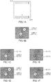
- the CMOS sensor scans from a coordinate (0, 0) to a coordinate (X, Y) in a direction indicated by an arrow.
- a label 1 is allocated to the detected signal (light source A)
- a label 2 is allocated to the detected signal (light source B).
- the CMOS sensor when the light source A is turned off, the CMOS sensor sets the label 1 to a dead number. Thereafter, as illustrated in Fig. 1(d) , when the light source A is turned on, the CMOS sensor allocates the label 1 to the light source A again. In this case, the label 1 is constantly allocated to the light source A and the label 2 is constantly allocated to the light source B, and thus no problem occurs.
- the CMOS sensor sets the labels 1 and 2 to dead numbers. Thereafter, as illustrated in Fig. 1(f) , when the light source B is turned on, the CMOS sensor allocates the label 1 to the light source B. In this case, although the label 2 is first allocated to the light source B, the label 1 is allocated when the light source B is turned off and then is turned on again, and thus the CMOS sensor erroneously detects the light source A in place of the light source B. In other words, the CMOS sensor erroneously detects the first remote control device and the second remote control device as each other.
- a remote control device for transmitting a light signal having a pulse pattern capable of reducing the possibility of false detection
- a communication device including the remote control device and a sensor
- a variable device further including an appliance whose state varies by tracking the remote control device
- a lighting device further including a moving light for tracking and illuminating the remote control device.
- a remote control device transmits a light signal having a pulse pattern to be detected by a sensor, in which the pulse pattern includes a first ON period, a second ON period and an OFF period between the first ON period and the second ON period, the first ON period and the second ON period being repeated alternately, the first ON period and the second ON period are more than twice as long as a sampling time T of the sensor, the first ON period and the second ON period are different from each other, and the OFF period is longer than the sampling time T.
- the first ON period and the second ON period be (n + 0.5) x T and the OFF period be 1.5 T, where T is the sampling time and n is an integer of 2 or more.
- a communication device includes:
- the senor it is preferable for the sensor to assume a period including two of the first ON periods and two of the second ON periods to be one cycle.
- the senor it is preferable for the sensor to detect the light signal based on a detected area of a light source or a change rate of a coordinate.
- a variable device includes:
- a lighting device includes:
- the moving light it is preferable for the moving light to disregard the detected light signal when direction information about a tilt exceeds a predetermined threshold.
- Fig. 2 is a perspective view of a lighting device according to the present invention.
- a lighting device 100 includes four remote control devices 10a to 10d, a sensor 20 which is, for example, a CMOS sensor 20, and a moving light 30.
- a sensor 20 which is, for example, a CMOS sensor 20, and a moving light 30.
- the remote control devices 10a to 10d are simply referred to as the remote control device 10.
- a light signal (for example, a pulse signal of light having any wavelength range, such as an infrared signal, a visible light signal, or an ultraviolet light signal) from each remote control device 10 is received by the CMOS sensor 20, and the moving light 30 is controlled to track and illuminate the remote control device 10 that has transmitted the signal.
- a device including the remote control device 10 and the CMOS sensor 20 is referred to as a communication device.
- Fig. 3 is a block diagram of the remote control device.
- the remote control device 10 includes a control unit 11, a signal storage unit 12 and a signal transmission unit 13. Upon detecting that a user has turned on a power supply of the remote control device 10, the control unit 11 transmits a signal as the light signal based on a signal pattern stored in the signal storage unit 12 through the signal transmission unit 13. As described below with reference to Fig. 6 , the signal patterns stored in the signal storage unit 12 are unique for each of the remote control devices 10a to 10d (i.e., the signal patterns stored in the signal storage unit 12 are different in the respective remote control devices 10a to 10d).
- the remote control devices 10a to 10d are used such that, for example, the remote control devices 10a to 10d are held by four users, respectively, with their hands, or are attached to the clothes or the like of the respective users.
- Fig. 4 is a block diagram of the CMOS sensor.
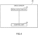
- the CMOS sensor 20 includes a signal detection unit 21 and a control unit 22.
- the signal detection unit 21 detects signals from the remote control devices 10a to 10d. Specifically, as described above with reference to Fig. 1(a) , the signal detection unit 21 scans from a coordinate (0, 0) to a coordinate (X, Y).
- a CMOS sampling time (a time required for scanning from the coordinate (0, 0) to the coordinate (X, Y)) is, for example, 8 ms, but any time can be set as the sampling time.
- the CMOS sensor detects the signal (light source A) from the remote control device 10a at a coordinate (X1, Y1) and detects the signal (light source B) from the remote control device 10b at a coordinate (X2, Y2). Note that for simplicity of explanation, the illustration of the signals from the remote control devices 10c and 10d is omitted.
- the control unit 22 allocates labels to signals detected at each sampling time in the order of scanning.
- a label 1 is allocated to the signal (light source A) from the remote control device 10a
- a label 2 is allocated to the signal (light source B) from the remote control device 10b.
- the control unit 22 transmits label information to the moving light 30 by a wired connection or a wireless connection.
- the label information includes coordinate (position) information of the light sources to which the labels are allocated.
- the moving light 30 includes a clockwise/counterclockwise rotation unit 31, an arm 32 fixed to a lower side of the clockwise/counterclockwise rotation unit 31, a hood 33 held by the arm 32 and a lighting appliance 34 placed inside the hood 33.
- the clockwise/counterclockwise rotation unit 31 includes a pan motor Mp and a variable control unit 35.
- the clockwise/counterclockwise rotation unit 31 is connected to a fixing portion of a ceiling and configured to be rotatable clockwise or counterclockwise by the pan motor Mp. Further, the clockwise/counterclockwise rotation unit 31 can hold the arm 32 and pan an illumination direction L of the lighting appliance 34 in a left-right direction by the rotation of the pan motor Mp.
- the hood 33 is held by the arm 32 and configured to be rotatable upward or downward by a tilt motor Mt attached to the arm 32.
- the illumination direction L of the lighting appliance 34 can be tilted up and down by the rotation of the tilt motor Mt.
- the hood 33 is configured to be able to adjust a focal length of the lighting appliance 34 using the focus motor Mf and a lens which is not illustrated.
- Fig. 5 is a block diagram of the moving light.
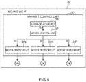
- the variable control unit 35 includes a communication unit 36 for receiving label information from the CMOS sensor 20, a motor control unit 37 for controlling the motor, and motor drive circuits 38p, 38t and 38f.
- the variable control unit 35 variably controls the rotational speed of each of the pan motor Mp, the tilt motor Mt and the focus motor Mf.
- the motor drive circuits 38p, 38t and 38f are simply referred to as the motor drive circuit 38
- the pan motor Mp, the tilt motor Mt and the focus motor Mf are simply referred to as the motor M.
- the communication unit 36 receives label information from the CMOS sensor 20 by a wired connection or a wireless connection, and outputs a reception signal Sm based on the label information.
- the communication unit 36 decodes an ON signal or an OFF signal based on the label information, specifies a target light source to be tracked depending on the decoding result, determines direction information (pan, tilt, focus) and a rotation direction (plus, minus) of the motor, and outputs these signals to the motor control unit 37.
- the motor control unit 37 generates instruction signals Sp, St and Sf for controlling the rotational speed of any one of the motors M based on the reception signal Sm.
- the instruction signals Sp, St and Sf are not particularly distinguished, the instruction signals Sp, St and Sf are simply referred to as the instruction signal S.
- the instruction signal S output to the motor drive circuit 38 by the motor control unit 37 includes an instruction for the rotation direction of the motor M. For example, if the instruction signal S is switched from plus to minus, the rotation direction of the motor M is reversed.
- the motor drive circuit 38p drives the pan motor Mp at the rotational speed in response to the instruction signal Sp.
- the pan motor Mp adjusts the illumination direction L of the lighting appliance 34 leftward or rightward.
- the motor drive circuit 38t drives the tilt motor Mt at the rotational speed in response to the instruction signal St.
- the tilt motor Mt adjusts the illumination direction L of the lighting appliance 34 upward or downward.
- the motor drive circuit 38f drives the focus motor Mf at the rotational speed in response to the instruction signal Sf.
- the focus motor Mf adjusts the focal length of the lighting appliance 34 forward or backward.
- the present embodiment illustrates an example where all of pan, tilt and zoom states of the lighting appliance 34 are adjusted (controlled), but any one of the pan, tilt and zoom states may be adjusted (controlled).
- a broadcast appliance such as a monitoring camera or a camera for broadcasting may be used as a control target appliance to adjust (control) states such as pan, tilt and zoom states.
- a projector as typified by a liquid crystal projector, a DLP projector (R), and the like may be used as a control target appliance to adjust (control) states such as focus and a projection angle on a screen by the motor.
- a device including the communication device (including the remote control device 10 and the CMOS sensor 20) and an appliance (a camera, a projector, etc.) whose state varies by tracking the remote control device 10 is referred to as a variable device.
- Fig. 6 illustrates pulse patterns of transmission signals from the remote control devices 10a to 10d.
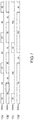
- the pulse pattern includes a first ON period (20 ms) and a second ON period (68 ms), which are repeated alternately, and an OFF period (12 ms) is included between the first ON period and the second ON period.
- the CMOS sensor 20 detects the OFF signal at least once in the OFF period.
- the first ON period and the second ON period are more than twice as long as the sampling time T, and the first ON period and the second ON period are different from each other. Accordingly, the ON signal can be detected twice or more in each of the first ON period and the second ON period. Since the OFF period is longer than the sampling time T, the OFF signal can be detected once or more in the OFF period.
- the remote control devices 10a to 10d include respectively different first ON periods and different second ON periods, which makes it possible to reduce the possibility of false detection in the remote control devices 10a to 10d.
- the first ON period and the second ON period are (n + 0.5) x T and the OFF period is 1.5 T, where T is the sampling time and n is an integer of 2 or more.
- the first ON period and the second ON period are more than twice as long as the sampling time T and different from each other, the first ON period and the second ON period may be 2.1 T, for example.
- the OFF period may be 1.1 T, for example.
- CMOS sensor 20 it is preferable for the CMOS sensor 20 to perform detection, assuming that a period including two first ON periods and two second ON periods is one cycle.
- one cycle of each of the remote control devices 10a and 10b is 224 ms and one cycle of each of the remote control devices 10c and 10d is 480 ms.
- Fig. 7 illustrates pulse patterns of transmission signals from remote control devices according to a Comparative Example.
- the CMOS sensor 20 cannot detect the ON signal in a portion indicated by a dashed circle in Fig. 7 . In this case, assuming that a period including one ON period and one OFF period is one cycle, the CMOS sensor 20 cannot distinguish the remote control devices 10a' and 10b'.
- a remote control device 10c' if the OFF period (160 ms) is longer than the ON period (40 ms), the problem of false detection due to the replacement as described above is likely to occur.
- the OFF period be shorter than each of the first ON period and the second ON period.
- the control unit 22 of the CMOS sensor 20 can allocate labels in consideration of not only the above-described pulse pattern, but also a detected area of a light source or a change rate of a coordinate.
- the CMOS sensor 20 detects a predetermined pattern of the remote control device 10a as illustrated in Fig. 6 , if the sensor light receiving area where the CMOS sensor 20 has received light from the light source greatly varies, or if the coordinate (position) of the light source greatly varies, the label 1 cannot be allocated to the detected light source, and it is determined that the light source is not an object to be tracked (the tracked object is lost).
- This configuration makes it possible to further reduce the possibility of false detection by performing detection with higher accuracy.
- the variable control unit 35 of the moving light 30 can also disregard the label information.
- the moving light 30 installed on the ceiling can avoid erroneously recognizing a light source of a lighting appliance installed near the same ceiling as the light source of the remote control device 10.
Landscapes
- Engineering & Computer Science (AREA)
- Computer Networks & Wireless Communication (AREA)
- Selective Calling Equipment (AREA)
- Circuit Arrangement For Electric Light Sources In General (AREA)
Abstract
Description
- The present invention relates to a remote control device for transmitting a light signal having a pulse pattern to be detected by a sensor, a communication device including the remote control device and a sensor, a variable device further including an appliance whose state varies by tracking the remote control device, and a lighting device further including a moving light for tracking and illuminating the remote control device.
- A technique is proposed in which, when a speaker carrying a remote control device for transmitting an infrared signal moves on a stage in a theater, a lecture hall, or the like, the infrared signal is detected so that a moving light illuminates the speaker by tracking the speaker (for example, Patent Literature 1).
- Patent Literature 1: Japanese Patent Application Publication No.
H05-20904 - If a plurality of speakers each carrying remote control devices are on the stage, it is necessary to distinguish and detect signals from the respective remote control devices. In this regard, a case where signals transmitted by two remote control devices are detected by a CMOS sensor is hereinafter considered.
- As illustrated in
Fig. 1(a) , the CMOS sensor scans from a coordinate (0, 0) to a coordinate (X, Y) in a direction indicated by an arrow. Here, as illustrated inFig. 1(b) , when the CMOS sensor detects a signal (light source A) from a first remote control device at a coordinate (X1, Y1), a label 1 is allocated to the detected signal (light source A), and when the CMOS sensor detects a signal (light source B) from a second remote control device at a coordinate (X2, Y2), a label 2 is allocated to the detected signal (light source B). Thereafter, as illustrated inFig. 1(c) , when the light source A is turned off, the CMOS sensor sets the label 1 to a dead number. Thereafter, as illustrated inFig. 1(d) , when the light source A is turned on, the CMOS sensor allocates the label 1 to the light source A again. In this case, the label 1 is constantly allocated to the light source A and the label 2 is constantly allocated to the light source B, and thus no problem occurs. - However, in the case illustrated in
Figs. 1(e) and 1(f) afterFig. 1(b) , a problem to be described below occurs. - After
Fig. 1(b) , as illustrated inFig. 1(e) , when both the light source A and the light source B are turned off, the CMOS sensor sets the labels 1 and 2 to dead numbers. Thereafter, as illustrated inFig. 1(f) , when the light source B is turned on, the CMOS sensor allocates the label 1 to the light source B. In this case, although the label 2 is first allocated to the light source B, the label 1 is allocated when the light source B is turned off and then is turned on again, and thus the CMOS sensor erroneously detects the light source A in place of the light source B. In other words, the CMOS sensor erroneously detects the first remote control device and the second remote control device as each other. - In view of the above-described problem, it is an object of the present invention to provide a remote control device for transmitting a light signal having a pulse pattern capable of reducing the possibility of false detection, a communication device including the remote control device and a sensor, a variable device further including an appliance whose state varies by tracking the remote control device, and a lighting device further including a moving light for tracking and illuminating the remote control device.
- A remote control device according to the present invention transmits a light signal having a pulse pattern to be detected by a sensor, in which
the pulse pattern includes a first ON period, a second ON period and an OFF period between the first ON period and the second ON period, the first ON period and the second ON period being repeated alternately,
the first ON period and the second ON period are more than twice as long as a sampling time T of the sensor,
the first ON period and the second ON period are different from each other, and
the OFF period is longer than the sampling time T. - In the remote control device according to the present invention, it is preferable that the first ON period and the second ON period be (n + 0.5) x T and the OFF period be 1.5 T, where T is the sampling time and n is an integer of 2 or more.
- A communication device according to the present invention includes:
- the remote control device; and
- a sensor for detecting a light signal transmitted by the remote control device.
- In the communication device according to the present invention, it is preferable for the sensor to assume a period including two of the first ON periods and two of the second ON periods to be one cycle.
- In the communication device according to the present invention, it is preferable for the sensor to detect the light signal based on a detected area of a light source or a change rate of a coordinate.
- A variable device according to the present invention includes:
- the communication device; and
- an appliance whose state varies by tracking the remote control device based on information from the sensor.
- A lighting device according to the present invention includes:
- the communication device; and
- a moving light for tracking and illuminating the remote control device based on information from the sensor.
- In the lighting device according to the present invention, it is preferable for the moving light to disregard the detected light signal when direction information about a tilt exceeds a predetermined threshold.
-
- [
Fig. 1 ] A diagram for explaining an operation of a CMOS sensor. - [
Fig. 2 ] A perspective view of a lighting device according to the present invention. - [
Fig. 3 ] A block diagram of a remote control device. - [
Fig. 4 ] A block diagram of the CMOS sensor. - [
Fig. 5 ] A block diagram of a moving light. - [
Fig. 6 ] Pulse patterns of transmission signals from the remote control devices according to the present invention. - [
Fig. 7 ] Pulse patterns of transmission signals from remote control devices according to a Comparative Example. -
Fig. 2 is a perspective view of a lighting device according to the present invention. - A
lighting device 100 includes fourremote control devices 10a to 10d, asensor 20 which is, for example, aCMOS sensor 20, and a movinglight 30. Hereinafter, when theremote control devices 10a to 10d are not particularly distinguished, theremote control devices 10a to 10d are simply referred to as theremote control device 10. A light signal (for example, a pulse signal of light having any wavelength range, such as an infrared signal, a visible light signal, or an ultraviolet light signal) from eachremote control device 10 is received by theCMOS sensor 20, and the movinglight 30 is controlled to track and illuminate theremote control device 10 that has transmitted the signal. - Herein, a device including the
remote control device 10 and theCMOS sensor 20 is referred to as a communication device. -
Fig. 3 is a block diagram of the remote control device. - The
remote control device 10 includes acontrol unit 11, asignal storage unit 12 and asignal transmission unit 13. Upon detecting that a user has turned on a power supply of theremote control device 10, thecontrol unit 11 transmits a signal as the light signal based on a signal pattern stored in thesignal storage unit 12 through thesignal transmission unit 13. As described below with reference toFig. 6 , the signal patterns stored in thesignal storage unit 12 are unique for each of theremote control devices 10a to 10d (i.e., the signal patterns stored in thesignal storage unit 12 are different in the respectiveremote control devices 10a to 10d). - The
remote control devices 10a to 10d are used such that, for example, theremote control devices 10a to 10d are held by four users, respectively, with their hands, or are attached to the clothes or the like of the respective users. -
Fig. 4 is a block diagram of the CMOS sensor. - The
CMOS sensor 20 includes asignal detection unit 21 and acontrol unit 22. Thesignal detection unit 21 detects signals from theremote control devices 10a to 10d. Specifically, as described above with reference toFig. 1(a) , thesignal detection unit 21 scans from a coordinate (0, 0) to a coordinate (X, Y). A CMOS sampling time (a time required for scanning from the coordinate (0, 0) to the coordinate (X, Y)) is, for example, 8 ms, but any time can be set as the sampling time. Here, as illustrated inFig. 1(b) , the CMOS sensor detects the signal (light source A) from theremote control device 10a at a coordinate (X1, Y1) and detects the signal (light source B) from theremote control device 10b at a coordinate (X2, Y2). Note that for simplicity of explanation, the illustration of the signals from theremote control devices - Thereafter, the
control unit 22 allocates labels to signals detected at each sampling time in the order of scanning. In the case ofFig. 1(b) , a label 1 is allocated to the signal (light source A) from theremote control device 10a, and a label 2 is allocated to the signal (light source B) from theremote control device 10b. Thecontrol unit 22 transmits label information to the movinglight 30 by a wired connection or a wireless connection. The label information includes coordinate (position) information of the light sources to which the labels are allocated. - Referring again to
Fig. 2 , the configuration and operation of the moving light will be described. - The moving
light 30 includes a clockwise/counterclockwise rotation unit 31, anarm 32 fixed to a lower side of the clockwise/counterclockwise rotation unit 31, ahood 33 held by thearm 32 and alighting appliance 34 placed inside thehood 33. - The clockwise/
counterclockwise rotation unit 31 includes a pan motor Mp and avariable control unit 35. The clockwise/counterclockwise rotation unit 31 is connected to a fixing portion of a ceiling and configured to be rotatable clockwise or counterclockwise by the pan motor Mp. Further, the clockwise/counterclockwise rotation unit 31 can hold thearm 32 and pan an illumination direction L of thelighting appliance 34 in a left-right direction by the rotation of the pan motor Mp. - The
hood 33 is held by thearm 32 and configured to be rotatable upward or downward by a tilt motor Mt attached to thearm 32. The illumination direction L of thelighting appliance 34 can be tilted up and down by the rotation of the tilt motor Mt. Thehood 33 is configured to be able to adjust a focal length of thelighting appliance 34 using the focus motor Mf and a lens which is not illustrated. -
Fig. 5 is a block diagram of the moving light. - The
variable control unit 35 includes acommunication unit 36 for receiving label information from theCMOS sensor 20, amotor control unit 37 for controlling the motor, andmotor drive circuits variable control unit 35 variably controls the rotational speed of each of the pan motor Mp, the tilt motor Mt and the focus motor Mf. Hereinafter, when themotor drive circuits motor drive circuits - The
communication unit 36 receives label information from theCMOS sensor 20 by a wired connection or a wireless connection, and outputs a reception signal Sm based on the label information. Thecommunication unit 36 decodes an ON signal or an OFF signal based on the label information, specifies a target light source to be tracked depending on the decoding result, determines direction information (pan, tilt, focus) and a rotation direction (plus, minus) of the motor, and outputs these signals to themotor control unit 37. - The
motor control unit 37 generates instruction signals Sp, St and Sf for controlling the rotational speed of any one of the motors M based on the reception signal Sm. Hereinafter, when the instruction signals Sp, St and Sf are not particularly distinguished, the instruction signals Sp, St and Sf are simply referred to as the instruction signal S. The instruction signal S output to the motor drive circuit 38 by themotor control unit 37 includes an instruction for the rotation direction of the motor M. For example, if the instruction signal S is switched from plus to minus, the rotation direction of the motor M is reversed. - The
motor drive circuit 38p drives the pan motor Mp at the rotational speed in response to the instruction signal Sp. The pan motor Mp adjusts the illumination direction L of thelighting appliance 34 leftward or rightward. - The
motor drive circuit 38t drives the tilt motor Mt at the rotational speed in response to the instruction signal St. The tilt motor Mt adjusts the illumination direction L of thelighting appliance 34 upward or downward. - The
motor drive circuit 38f drives the focus motor Mf at the rotational speed in response to the instruction signal Sf. The focus motor Mf adjusts the focal length of thelighting appliance 34 forward or backward. - Note that the present embodiment illustrates an example where all of pan, tilt and zoom states of the
lighting appliance 34 are adjusted (controlled), but any one of the pan, tilt and zoom states may be adjusted (controlled). Further, a broadcast appliance such as a monitoring camera or a camera for broadcasting may be used as a control target appliance to adjust (control) states such as pan, tilt and zoom states. Furthermore, a projector as typified by a liquid crystal projector, a DLP projector (R), and the like may be used as a control target appliance to adjust (control) states such as focus and a projection angle on a screen by the motor. - Herein, a device including the communication device (including the
remote control device 10 and the CMOS sensor 20) and an appliance (a camera, a projector, etc.) whose state varies by tracking theremote control device 10 is referred to as a variable device. -
Fig. 6 illustrates pulse patterns of transmission signals from theremote control devices 10a to 10d. - In the
remote control device 10a, the pulse pattern includes a first ON period (20 ms) and a second ON period (68 ms), which are repeated alternately, and an OFF period (12 ms) is included between the first ON period and the second ON period. As described above, since a sampling time T of theCMOS sensor 20 is 8 ms, theCMOS sensor 20 detects the ON signal twice or three times (which indicates that theremote control device 10a is turned on) in the first ON period (20 ms = 2.5 T). For example, if sampling is performed at 8 ms and 16 ms, theCMOS sensor 20 detects the ON signal twice, and if sampling is performed at 3 ms, 11 ms, and 19 ms, theCMOS sensor 20 detects theON signal 3 times. Further, theCMOS sensor 20 detects the ON signal 8 times or 9 times in the second ON period (68 ms = 8.5 T) and detects the OFF signal at least once (which indicates that theremote control device 10a is turned off) in the OFF period (12 ms = 1.5 T). - In the
remote control device 10b, the pulse pattern includes the first ON period (36 ms) and the second ON period (52 ms), which are repeated alternately. Therefore, theCMOS sensor 20 detects the ON signal 4 times or 5 times in the first ON period (36 ms = 4.5 T) and detects the ON signal 6 times or 7 times in the second ON period (52 ms = 6.5 T). - In the
remote control device 10c, the pulse pattern includes the first ON period (84 ms) and the second ON period (132 ms), which are repeated alternately. Therefore, theCMOS sensor 20 detects theON signal 10 times or 11 times in the first ON period (84 ms = 10.5 T) and detects the ON signal 16 times or 17 times in the second ON period (132 ms = 16.5 T). - In the
remote control device 10d, the pulse pattern includes the first ON period (100 ms) and the second ON period (116 ms), which are repeated alternately. Therefore, theCMOS sensor 20 detects theON signal 12 times or 13 times in the first ON period (100 ms = 12.5 T) and detects the ON signal 14 times or 15 times in the second ON period (116 ms = 14.5 T). - Since the
remote control devices 10a to 10d have the same OFF period of 12 ms, theCMOS sensor 20 detects the OFF signal at least once in the OFF period. - As described above, the first ON period and the second ON period are more than twice as long as the sampling time T, and the first ON period and the second ON period are different from each other. Accordingly, the ON signal can be detected twice or more in each of the first ON period and the second ON period. Since the OFF period is longer than the sampling time T, the OFF signal can be detected once or more in the OFF period.
- Further, the
remote control devices 10a to 10d include respectively different first ON periods and different second ON periods, which makes it possible to reduce the possibility of false detection in theremote control devices 10a to 10d. - Preferably, the first ON period and the second ON period are (n + 0.5) x T and the OFF period is 1.5 T, where T is the sampling time and n is an integer of 2 or more. Through use of these settings, even when the sampling start of the
CMOS sensor 20 is not synchronized with the pulse pattern of each of theremote control devices 10a to 10d, theCMOS sensor 20 can reliably detect the ON signal twice or more in each of the first ON period and the second ON period and can reliably detect the OFF signal once or more in the OFF period. - As long as the first ON period and the second ON period are more than twice as long as the sampling time T and different from each other, the first ON period and the second ON period may be 2.1 T, for example. As long as the OFF period is longer than the sampling time T, the OFF period may be 1.1 T, for example.
- It is preferable for the
CMOS sensor 20 to perform detection, assuming that a period including two first ON periods and two second ON periods is one cycle. In the case of the pulse pattern illustrated inFig. 6 , one cycle of each of theremote control devices remote control devices -
Fig. 7 illustrates pulse patterns of transmission signals from remote control devices according to a Comparative Example. - In a
remote control device 10a', the pulse pattern includes the ON period (40 ms) and the OFF period (80 ms), which are repeated alternately. Accordingly, theCMOS sensor 20 detects the ON signal 5 times or 6 times in the ON period (40 ms = 5 T) and detects theOFF signal 10 times or 11 times in the OFF period (80 ms = 10 T). - In a
remote control device 10b', the pulse pattern includes the ON period (80 ms) and the OFF period (40 ms), which are repeated alternately. Accordingly, theCMOS sensor 20 detects theON signal 10 times or 11 times in the ON period (80 ms = 10 T) and detects the OFF signal 5 times or 6 times in the OFF period (40 ms = 5 T). - A case is assumed: although the
remote control device 10b' transmits the above-described pulse pattern, when the user carrying theremote control device 10b' substantially moves or when the signal transmission unit of theremote control device 10b' is hidden, theCMOS sensor 20 cannot detect the ON signal in a portion indicated by a dashed circle inFig. 7 . In this case, assuming that a period including one ON period and one OFF period is one cycle, theCMOS sensor 20 cannot distinguish theremote control devices 10a' and 10b'. - Therefore, according to the present invention, it is possible to reduce the possibility of false detection in the remote control devices by increasing the complexity of the pulse pattern using two ON signals with different widths as illustrated in
Fig. 6 . - Further, as illustrated in a
remote control device 10c', if the OFF period (160 ms) is longer than the ON period (40 ms), the problem of false detection due to the replacement as described above is likely to occur. - Therefore, according to the present invention, it is preferable that the OFF period be shorter than each of the first ON period and the second ON period.
- Note that there is a possibility that false detection may occur due to light signals, such as sunlight, from light sources different from the
remote control device 10. Therefore, it is possible to reduce the possibility of false detection by increasing the complexity of the pulse pattern. - The
control unit 22 of theCMOS sensor 20 can allocate labels in consideration of not only the above-described pulse pattern, but also a detected area of a light source or a change rate of a coordinate. - For example, even when the
CMOS sensor 20 detects a predetermined pattern of theremote control device 10a as illustrated inFig. 6 , if the sensor light receiving area where theCMOS sensor 20 has received light from the light source greatly varies, or if the coordinate (position) of the light source greatly varies, the label 1 cannot be allocated to the detected light source, and it is determined that the light source is not an object to be tracked (the tracked object is lost). This configuration makes it possible to further reduce the possibility of false detection by performing detection with higher accuracy. - Further, on the premise that the
remote control device 10 is carried by the user and present on the stage or the like and thus not present in the vicinity of the ceiling, if direction information about a tilt exceeds a predetermined threshold, or if the movinglight 30 receives label information indicating that the vicinity of the ceiling is illuminated, thevariable control unit 35 of the movinglight 30 can also disregard the label information. Through use of this configuration, the movinglight 30 installed on the ceiling can avoid erroneously recognizing a light source of a lighting appliance installed near the same ceiling as the light source of theremote control device 10. - The present invention is not limited to the above-described embodiments and can be modified and implemented without departing from the scope of the present invention. Examples of modifications include the following (a) to (c).
- (a) The plurality of
remote control devices 10a to 10d is not indispensable. A plurality of pulse patterns may be stored in thesignal storage unit 12 of a single remote control device, and the pulse patterns may be switched by a pulse pattern selection switch. - (b) The number of pulse patterns is not limited to four. Two, three, five, or more pulse patterns may be used.
- (c) The sensor is not limited to a CMOS sensor and is not particularly limited as long as the sensor can detect light. Any type of sensor may be used.
-
- 10, 10a, 10b, 10c, 10d
- remote control device
- 11
- control unit
- 12
- signal storage unit
- 13
- signal transmission unit
- 20
- CMOS sensor (sensor)
- 21
- signal detection unit
- 22
- control unit
- 30
- moving light
- 31
- clockwise/counterclockwise rotation unit
- 34
- lighting appliance
- 35
- variable control unit
- 36
- communication unit
- 37
- motor control unit
- 38p, 38t, 38f
- motor drive circuit
- 100
- lighting device
- Mp
- pan motor
- Mt
- tilt motor
- Mf
- focus motor
- Sm
- reception signal
- Sp, St, Sf
- instruction signal
Claims (8)
- A remote control device for transmitting a light signal having a pulse pattern to be detected by a sensor, wherein
the pulse pattern includes a first ON period, a second ON period and an OFF period between the first ON period and the second ON period, the first ON period and the second ON period being repeated alternately,
the first ON period and the second ON period are more than twice as long as a sampling time T of the sensor,
the first ON period and the second ON period are different from each other, and
the OFF period is longer than the sampling time T. - The remote control device according to claim 1, wherein
the first ON period and the second ON period are (n + 0.5) x T and the OFF period is 1.5 T,
where T is the sampling time and n is an integer of 2 or more. - A communication device comprising:the remote control device according to claim 1 or 2; anda sensor for detecting a light signal transmitted by the remote control device.
- The communication device according to claim 3, wherein
the sensor assumes a period including two of the first ON periods and two of the second ON periods to be one cycle. - The communication device according to claim 3 or 4, wherein
the sensor detects the light signal based on a detected area of a light source or a change rate of a coordinate. - A variable device comprising:the communication device according to any one of claims 3 to 5; andan appliance whose state varies by tracking the remote control device based on information from the sensor.
- A lighting device comprising:the communication device according to any one of claims 3 to 5; anda moving light for tracking and illuminating the remote control device based on information from the sensor.
- The lighting device according to claim 7, wherein
the moving light disregards the detected light signal when direction information about a tilt exceeds a predetermined threshold.
Applications Claiming Priority (2)
| Application Number | Priority Date | Filing Date | Title |
|---|---|---|---|
| JP2018014914A JP6975057B2 (en) | 2018-01-31 | 2018-01-31 | Remote control device, communication device, variable device and lighting device |
| PCT/JP2018/046293 WO2019150795A1 (en) | 2018-01-31 | 2018-12-17 | Remote control device, communication device, variable device, and lighting device |
Publications (3)
| Publication Number | Publication Date |
|---|---|
| EP3748985A1 true EP3748985A1 (en) | 2020-12-09 |
| EP3748985A4 EP3748985A4 (en) | 2021-10-13 |
| EP3748985B1 EP3748985B1 (en) | 2024-10-30 |
Family
ID=67479389
Family Applications (1)
| Application Number | Title | Priority Date | Filing Date |
|---|---|---|---|
| EP18903878.9A Active EP3748985B1 (en) | 2018-01-31 | 2018-12-17 | Remote control device, communication device, variable device, and lighting device |
Country Status (5)
| Country | Link |
|---|---|
| US (1) | US11206723B2 (en) |
| EP (1) | EP3748985B1 (en) |
| JP (1) | JP6975057B2 (en) |
| CN (1) | CN111656798B (en) |
| WO (1) | WO2019150795A1 (en) |
Family Cites Families (19)
| Publication number | Priority date | Publication date | Assignee | Title |
|---|---|---|---|---|
| JPS5636887A (en) * | 1979-08-31 | 1981-04-10 | Matsushita Electric Works Ltd | Spotlight with automatic tracking device |
| US6430358B1 (en) * | 1988-12-23 | 2002-08-06 | Gemstar Development Corporation | Universal remote including apparatus using compressed codes for video recorder control |
| US5113438A (en) * | 1990-06-25 | 1992-05-12 | Cablesoft, Inc. | Method and apparatus for jamming infrared remote controls |
| JPH0520904A (en) * | 1991-07-12 | 1993-01-29 | Sony Corp | Lighting system |
| US5379453A (en) * | 1992-09-24 | 1995-01-03 | Colorado Meadowlark Corporation | Remote control system |
| WO1995031871A1 (en) * | 1994-05-16 | 1995-11-23 | Mankovitz Roy J | Television program record scheduling and satellite receiver control using compressed codes |
| US6909471B2 (en) * | 2002-12-03 | 2005-06-21 | Scientific-Atlanta, Inc. | Audio volume control |
| JP4590171B2 (en) * | 2003-08-29 | 2010-12-01 | オリンパス株式会社 | Capsule type medical device and medical device equipped with the capsule type medical device |
| US7332877B2 (en) * | 2003-11-24 | 2008-02-19 | Glowleds, Inc. | Light controller |
| JP2006155346A (en) | 2004-11-30 | 2006-06-15 | Sharp Corp | Remote control device and display device |
| US7663489B2 (en) * | 2006-04-28 | 2010-02-16 | Checkpoint Systems, Inc. | Alarm systems, wireless alarm devices, and article security methods |
| US8804483B2 (en) * | 2009-07-31 | 2014-08-12 | Qualcomm Incorporated | System and method for transmission and detection of frame including bursts of pulses |
| JP5466995B2 (en) * | 2010-05-24 | 2014-04-09 | パナソニック株式会社 | Remote control system for lighting |
| CN203519822U (en) | 2013-04-09 | 2014-04-02 | 北京半导体照明科技促进中心 | Visible-light-based indoor positioning device and system |
| JP6216145B2 (en) * | 2013-04-22 | 2017-10-18 | シナプティクス・ジャパン合同会社 | Touch panel controller and semiconductor device |
| EP3197539B1 (en) * | 2014-09-26 | 2025-03-19 | Duke University | Systems for spinal cord stimulation |
| US9885776B2 (en) * | 2015-07-29 | 2018-02-06 | Raytheon Company | Electronic enhanced receiver scheduler system |
| US20170104534A1 (en) * | 2015-10-12 | 2017-04-13 | Performance Designed Products Llc | Systems and methods for transmitting data between a remote device and a computing device |
| US10184807B2 (en) * | 2016-09-26 | 2019-01-22 | Infineon Technologies Ag | True-power-on and diagnostic-capable incremental interface for angular sensors |
-
2018
- 2018-01-31 JP JP2018014914A patent/JP6975057B2/en active Active
- 2018-12-17 CN CN201880087844.0A patent/CN111656798B/en active Active
- 2018-12-17 EP EP18903878.9A patent/EP3748985B1/en active Active
- 2018-12-17 US US16/965,404 patent/US11206723B2/en active Active
- 2018-12-17 WO PCT/JP2018/046293 patent/WO2019150795A1/en not_active Ceased
Also Published As
| Publication number | Publication date |
|---|---|
| US20210076473A1 (en) | 2021-03-11 |
| WO2019150795A1 (en) | 2019-08-08 |
| EP3748985A4 (en) | 2021-10-13 |
| CN111656798B (en) | 2022-06-14 |
| CN111656798A (en) | 2020-09-11 |
| JP2019134305A (en) | 2019-08-08 |
| JP6975057B2 (en) | 2021-12-01 |
| US11206723B2 (en) | 2021-12-21 |
| EP3748985B1 (en) | 2024-10-30 |
Similar Documents
| Publication | Publication Date | Title |
|---|---|---|
| ES2708695T3 (en) | Coded light detector | |
| ES2426751T3 (en) | Method, system and remote control to control the parameters of each of a multitude of light projectors | |
| JP6457910B2 (en) | Dimmer, lighting control system, control unit, and equipment control system | |
| EP3177866B1 (en) | Instrument control device, variable device, lighting control device, and variable lighting device | |
| CN108027123A (en) | LED projection lamp tool with additional lights effect | |
| CN101529978A (en) | System and method for light control | |
| WO2016031359A1 (en) | Control device, control method, and program | |
| EP3329616B1 (en) | Light emitting device for generating light with embedded information | |
| US11206723B2 (en) | Remote control device, communication device, variable device and lighting device | |
| TWI345128B (en) | Displaying method of digital light processing (dlp) projector and dlp projector | |
| JP2007295490A (en) | Visible light communication apparatus and visible light receiving method | |
| EP3635484A1 (en) | Image and light projection | |
| US20210259071A1 (en) | Self-identifying light fixture | |
| JP2014154068A (en) | Moving body detection device | |
| CN107370540B (en) | Localized explanation method based on visible light communication | |
| JP2012053603A (en) | Information display system | |
| JP2016225247A (en) | Optical projection device | |
| ATE223073T1 (en) | DIGITAL CAMERA WITH PANORAMA AND/OR ROTATION FUNCTION, AND ITS IMAGE ROTATION DEVICE | |
| JP2018010423A (en) | Alarm system | |
| TWI631874B (en) | Automatically adjustable directional control system and method thereof | |
| KR101340259B1 (en) | Lighting control apparatus | |
| JP2024050102A (en) | Illumination system, illumination device and transmission module | |
| EP4595705A1 (en) | Device and method for lighting control | |
| TR2023019810A2 (en) | A LIGHTING SYSTEM THAT CAN BE CONTROLLED WITH A SLIDING BODY | |
| JP2008099165A (en) | Electronics |
Legal Events
| Date | Code | Title | Description |
|---|---|---|---|
| STAA | Information on the status of an ep patent application or granted ep patent |
Free format text: STATUS: THE INTERNATIONAL PUBLICATION HAS BEEN MADE |
|
| PUAI | Public reference made under article 153(3) epc to a published international application that has entered the european phase |
Free format text: ORIGINAL CODE: 0009012 |
|
| STAA | Information on the status of an ep patent application or granted ep patent |
Free format text: STATUS: REQUEST FOR EXAMINATION WAS MADE |
|
| 17P | Request for examination filed |
Effective date: 20200826 |
|
| AK | Designated contracting states |
Kind code of ref document: A1 Designated state(s): AL AT BE BG CH CY CZ DE DK EE ES FI FR GB GR HR HU IE IS IT LI LT LU LV MC MK MT NL NO PL PT RO RS SE SI SK SM TR |
|
| AX | Request for extension of the european patent |
Extension state: BA ME |
|
| DAV | Request for validation of the european patent (deleted) | ||
| DAX | Request for extension of the european patent (deleted) | ||
| A4 | Supplementary search report drawn up and despatched |
Effective date: 20210915 |
|
| RIC1 | Information provided on ipc code assigned before grant |
Ipc: H05B 47/10 20200101ALI20210909BHEP Ipc: H05B 47/195 20200101ALI20210909BHEP Ipc: F21V 23/04 20060101ALI20210909BHEP Ipc: H04Q 9/00 20060101AFI20210909BHEP |
|
| STAA | Information on the status of an ep patent application or granted ep patent |
Free format text: STATUS: EXAMINATION IS IN PROGRESS |
|
| 17Q | First examination report despatched |
Effective date: 20221214 |
|
| REG | Reference to a national code |
Ref country code: DE Ref legal event code: R079 Ipc: F21V0021300000 Ref country code: DE Ref legal event code: R079 Ref document number: 602018076120 Country of ref document: DE Free format text: PREVIOUS MAIN CLASS: H04Q0009000000 Ipc: F21V0021300000 |
|
| GRAP | Despatch of communication of intention to grant a patent |
Free format text: ORIGINAL CODE: EPIDOSNIGR1 |
|
| STAA | Information on the status of an ep patent application or granted ep patent |
Free format text: STATUS: GRANT OF PATENT IS INTENDED |
|
| RIC1 | Information provided on ipc code assigned before grant |
Ipc: H04Q 9/00 20060101ALI20240425BHEP Ipc: H05B 47/195 20200101ALI20240425BHEP Ipc: H05B 47/10 20200101ALI20240425BHEP Ipc: F21V 21/15 20060101ALI20240425BHEP Ipc: F21V 21/30 20060101AFI20240425BHEP |
|
| INTG | Intention to grant announced |
Effective date: 20240524 |
|
| GRAS | Grant fee paid |
Free format text: ORIGINAL CODE: EPIDOSNIGR3 |
|
| GRAA | (expected) grant |
Free format text: ORIGINAL CODE: 0009210 |
|
| STAA | Information on the status of an ep patent application or granted ep patent |
Free format text: STATUS: THE PATENT HAS BEEN GRANTED |
|
| AK | Designated contracting states |
Kind code of ref document: B1 Designated state(s): AL AT BE BG CH CY CZ DE DK EE ES FI FR GB GR HR HU IE IS IT LI LT LU LV MC MK MT NL NO PL PT RO RS SE SI SK SM TR |
|
| REG | Reference to a national code |
Ref country code: GB Ref legal event code: FG4D |
|
| REG | Reference to a national code |
Ref country code: CH Ref legal event code: EP |
|
| P01 | Opt-out of the competence of the unified patent court (upc) registered |
Free format text: CASE NUMBER: APP_52601/2024 Effective date: 20240919 |
|
| REG | Reference to a national code |
Ref country code: IE Ref legal event code: FG4D |
|
| REG | Reference to a national code |
Ref country code: DE Ref legal event code: R096 Ref document number: 602018076120 Country of ref document: DE |
|
| REG | Reference to a national code |
Ref country code: LT Ref legal event code: MG9D |
|
| REG | Reference to a national code |
Ref country code: NL Ref legal event code: MP Effective date: 20241030 |
|
| PG25 | Lapsed in a contracting state [announced via postgrant information from national office to epo] |
Ref country code: HR Free format text: LAPSE BECAUSE OF FAILURE TO SUBMIT A TRANSLATION OF THE DESCRIPTION OR TO PAY THE FEE WITHIN THE PRESCRIBED TIME-LIMIT Effective date: 20241030 Ref country code: IS Free format text: LAPSE BECAUSE OF FAILURE TO SUBMIT A TRANSLATION OF THE DESCRIPTION OR TO PAY THE FEE WITHIN THE PRESCRIBED TIME-LIMIT Effective date: 20250228 Ref country code: PT Free format text: LAPSE BECAUSE OF FAILURE TO SUBMIT A TRANSLATION OF THE DESCRIPTION OR TO PAY THE FEE WITHIN THE PRESCRIBED TIME-LIMIT Effective date: 20250228 |
|
| PG25 | Lapsed in a contracting state [announced via postgrant information from national office to epo] |
Ref country code: FI Free format text: LAPSE BECAUSE OF FAILURE TO SUBMIT A TRANSLATION OF THE DESCRIPTION OR TO PAY THE FEE WITHIN THE PRESCRIBED TIME-LIMIT Effective date: 20241030 Ref country code: NL Free format text: LAPSE BECAUSE OF FAILURE TO SUBMIT A TRANSLATION OF THE DESCRIPTION OR TO PAY THE FEE WITHIN THE PRESCRIBED TIME-LIMIT Effective date: 20241030 |
|
| REG | Reference to a national code |
Ref country code: AT Ref legal event code: MK05 Ref document number: 1737181 Country of ref document: AT Kind code of ref document: T Effective date: 20241030 |
|
| PG25 | Lapsed in a contracting state [announced via postgrant information from national office to epo] |
Ref country code: BG Free format text: LAPSE BECAUSE OF FAILURE TO SUBMIT A TRANSLATION OF THE DESCRIPTION OR TO PAY THE FEE WITHIN THE PRESCRIBED TIME-LIMIT Effective date: 20241030 |
|
| PG25 | Lapsed in a contracting state [announced via postgrant information from national office to epo] |
Ref country code: ES Free format text: LAPSE BECAUSE OF FAILURE TO SUBMIT A TRANSLATION OF THE DESCRIPTION OR TO PAY THE FEE WITHIN THE PRESCRIBED TIME-LIMIT Effective date: 20241030 |
|
| PG25 | Lapsed in a contracting state [announced via postgrant information from national office to epo] |
Ref country code: NO Free format text: LAPSE BECAUSE OF FAILURE TO SUBMIT A TRANSLATION OF THE DESCRIPTION OR TO PAY THE FEE WITHIN THE PRESCRIBED TIME-LIMIT Effective date: 20250130 |
|
| PG25 | Lapsed in a contracting state [announced via postgrant information from national office to epo] |
Ref country code: AT Free format text: LAPSE BECAUSE OF FAILURE TO SUBMIT A TRANSLATION OF THE DESCRIPTION OR TO PAY THE FEE WITHIN THE PRESCRIBED TIME-LIMIT Effective date: 20241030 Ref country code: GR Free format text: LAPSE BECAUSE OF FAILURE TO SUBMIT A TRANSLATION OF THE DESCRIPTION OR TO PAY THE FEE WITHIN THE PRESCRIBED TIME-LIMIT Effective date: 20250131 Ref country code: LV Free format text: LAPSE BECAUSE OF FAILURE TO SUBMIT A TRANSLATION OF THE DESCRIPTION OR TO PAY THE FEE WITHIN THE PRESCRIBED TIME-LIMIT Effective date: 20241030 |
|
| PG25 | Lapsed in a contracting state [announced via postgrant information from national office to epo] |
Ref country code: PL Free format text: LAPSE BECAUSE OF FAILURE TO SUBMIT A TRANSLATION OF THE DESCRIPTION OR TO PAY THE FEE WITHIN THE PRESCRIBED TIME-LIMIT Effective date: 20241030 |
|
| PG25 | Lapsed in a contracting state [announced via postgrant information from national office to epo] |
Ref country code: RS Free format text: LAPSE BECAUSE OF FAILURE TO SUBMIT A TRANSLATION OF THE DESCRIPTION OR TO PAY THE FEE WITHIN THE PRESCRIBED TIME-LIMIT Effective date: 20250130 |
|
| PG25 | Lapsed in a contracting state [announced via postgrant information from national office to epo] |
Ref country code: SM Free format text: LAPSE BECAUSE OF FAILURE TO SUBMIT A TRANSLATION OF THE DESCRIPTION OR TO PAY THE FEE WITHIN THE PRESCRIBED TIME-LIMIT Effective date: 20241030 |
|
| PG25 | Lapsed in a contracting state [announced via postgrant information from national office to epo] |
Ref country code: MC Free format text: LAPSE BECAUSE OF FAILURE TO SUBMIT A TRANSLATION OF THE DESCRIPTION OR TO PAY THE FEE WITHIN THE PRESCRIBED TIME-LIMIT Effective date: 20241030 |
|
| PG25 | Lapsed in a contracting state [announced via postgrant information from national office to epo] |
Ref country code: DK Free format text: LAPSE BECAUSE OF FAILURE TO SUBMIT A TRANSLATION OF THE DESCRIPTION OR TO PAY THE FEE WITHIN THE PRESCRIBED TIME-LIMIT Effective date: 20241030 |
|
| PG25 | Lapsed in a contracting state [announced via postgrant information from national office to epo] |
Ref country code: EE Free format text: LAPSE BECAUSE OF FAILURE TO SUBMIT A TRANSLATION OF THE DESCRIPTION OR TO PAY THE FEE WITHIN THE PRESCRIBED TIME-LIMIT Effective date: 20241030 |
|
| PG25 | Lapsed in a contracting state [announced via postgrant information from national office to epo] |
Ref country code: RO Free format text: LAPSE BECAUSE OF FAILURE TO SUBMIT A TRANSLATION OF THE DESCRIPTION OR TO PAY THE FEE WITHIN THE PRESCRIBED TIME-LIMIT Effective date: 20241030 |
|
| PG25 | Lapsed in a contracting state [announced via postgrant information from national office to epo] |
Ref country code: SK Free format text: LAPSE BECAUSE OF FAILURE TO SUBMIT A TRANSLATION OF THE DESCRIPTION OR TO PAY THE FEE WITHIN THE PRESCRIBED TIME-LIMIT Effective date: 20241030 |
|
| PG25 | Lapsed in a contracting state [announced via postgrant information from national office to epo] |
Ref country code: CZ Free format text: LAPSE BECAUSE OF FAILURE TO SUBMIT A TRANSLATION OF THE DESCRIPTION OR TO PAY THE FEE WITHIN THE PRESCRIBED TIME-LIMIT Effective date: 20241030 |
|
| REG | Reference to a national code |
Ref country code: CH Ref legal event code: PL Ref country code: DE Ref legal event code: R097 Ref document number: 602018076120 Country of ref document: DE |
|
| PG25 | Lapsed in a contracting state [announced via postgrant information from national office to epo] |
Ref country code: LU Free format text: LAPSE BECAUSE OF NON-PAYMENT OF DUE FEES Effective date: 20241217 |
|
| PLBE | No opposition filed within time limit |
Free format text: ORIGINAL CODE: 0009261 |
|
| STAA | Information on the status of an ep patent application or granted ep patent |
Free format text: STATUS: NO OPPOSITION FILED WITHIN TIME LIMIT |
|
| PG25 | Lapsed in a contracting state [announced via postgrant information from national office to epo] |
Ref country code: SE Free format text: LAPSE BECAUSE OF FAILURE TO SUBMIT A TRANSLATION OF THE DESCRIPTION OR TO PAY THE FEE WITHIN THE PRESCRIBED TIME-LIMIT Effective date: 20241030 |
|
| GBPC | Gb: european patent ceased through non-payment of renewal fee |
Effective date: 20250130 |
|
| 26N | No opposition filed |
Effective date: 20250731 |
|
| REG | Reference to a national code |
Ref country code: BE Ref legal event code: MM Effective date: 20241231 |
|
| PG25 | Lapsed in a contracting state [announced via postgrant information from national office to epo] |
Ref country code: GB Free format text: LAPSE BECAUSE OF NON-PAYMENT OF DUE FEES Effective date: 20250130 Ref country code: BE Free format text: LAPSE BECAUSE OF NON-PAYMENT OF DUE FEES Effective date: 20241231 |
|
| PG25 | Lapsed in a contracting state [announced via postgrant information from national office to epo] |
Ref country code: CH Free format text: LAPSE BECAUSE OF NON-PAYMENT OF DUE FEES Effective date: 20241231 |
|
| PG25 | Lapsed in a contracting state [announced via postgrant information from national office to epo] |
Ref country code: IE Free format text: LAPSE BECAUSE OF NON-PAYMENT OF DUE FEES Effective date: 20241217 |
|
| PGFP | Annual fee paid to national office [announced via postgrant information from national office to epo] |
Ref country code: DE Payment date: 20251211 Year of fee payment: 8 |
|
| PGFP | Annual fee paid to national office [announced via postgrant information from national office to epo] |
Ref country code: IT Payment date: 20251223 Year of fee payment: 8 |
|
| PGFP | Annual fee paid to national office [announced via postgrant information from national office to epo] |
Ref country code: FR Payment date: 20251229 Year of fee payment: 8 |