EP3748983A1 - Video playback method, terminal apparatus, and storage medium - Google Patents
Video playback method, terminal apparatus, and storage medium Download PDFInfo
- Publication number
- EP3748983A1 EP3748983A1 EP19747355.6A EP19747355A EP3748983A1 EP 3748983 A1 EP3748983 A1 EP 3748983A1 EP 19747355 A EP19747355 A EP 19747355A EP 3748983 A1 EP3748983 A1 EP 3748983A1
- Authority
- EP
- European Patent Office
- Prior art keywords
- image frame
- window
- image
- determining
- video stream
- Prior art date
- Legal status (The legal status is an assumption and is not a legal conclusion. Google has not performed a legal analysis and makes no representation as to the accuracy of the status listed.)
- Granted
Links
Images






Classifications
-
- H—ELECTRICITY
- H04—ELECTRIC COMMUNICATION TECHNIQUE
- H04N—PICTORIAL COMMUNICATION, e.g. TELEVISION
- H04N21/00—Selective content distribution, e.g. interactive television or video on demand [VOD]
- H04N21/20—Servers specifically adapted for the distribution of content, e.g. VOD servers; Operations thereof
- H04N21/23—Processing of content or additional data; Elementary server operations; Server middleware
- H04N21/234—Processing of video elementary streams, e.g. splicing of video streams or manipulating encoded video stream scene graphs
- H04N21/2343—Processing of video elementary streams, e.g. splicing of video streams or manipulating encoded video stream scene graphs involving reformatting operations of video signals for distribution or compliance with end-user requests or end-user device requirements
- H04N21/23439—Processing of video elementary streams, e.g. splicing of video streams or manipulating encoded video stream scene graphs involving reformatting operations of video signals for distribution or compliance with end-user requests or end-user device requirements for generating different versions
-
- H—ELECTRICITY
- H04—ELECTRIC COMMUNICATION TECHNIQUE
- H04N—PICTORIAL COMMUNICATION, e.g. TELEVISION
- H04N21/00—Selective content distribution, e.g. interactive television or video on demand [VOD]
- H04N21/20—Servers specifically adapted for the distribution of content, e.g. VOD servers; Operations thereof
- H04N21/23—Processing of content or additional data; Elementary server operations; Server middleware
- H04N21/234—Processing of video elementary streams, e.g. splicing of video streams or manipulating encoded video stream scene graphs
- H04N21/23424—Processing of video elementary streams, e.g. splicing of video streams or manipulating encoded video stream scene graphs involving splicing one content stream with another content stream, e.g. for inserting or substituting an advertisement
-
- H—ELECTRICITY
- H04—ELECTRIC COMMUNICATION TECHNIQUE
- H04N—PICTORIAL COMMUNICATION, e.g. TELEVISION
- H04N21/00—Selective content distribution, e.g. interactive television or video on demand [VOD]
- H04N21/40—Client devices specifically adapted for the reception of or interaction with content, e.g. set-top-box [STB]; Operations thereof
- H04N21/43—Processing of content or additional data, e.g. demultiplexing additional data from a digital video stream; Elementary client operations, e.g. monitoring of home network or synchronising decoder's clock; Client middleware
- H04N21/431—Generation of visual interfaces for content selection or interaction; Content or additional data rendering
- H04N21/4312—Generation of visual interfaces for content selection or interaction; Content or additional data rendering involving specific graphical features, e.g. screen layout, special fonts or colors, blinking icons, highlights or animations
-
- H—ELECTRICITY
- H04—ELECTRIC COMMUNICATION TECHNIQUE
- H04N—PICTORIAL COMMUNICATION, e.g. TELEVISION
- H04N21/00—Selective content distribution, e.g. interactive television or video on demand [VOD]
- H04N21/40—Client devices specifically adapted for the reception of or interaction with content, e.g. set-top-box [STB]; Operations thereof
- H04N21/43—Processing of content or additional data, e.g. demultiplexing additional data from a digital video stream; Elementary client operations, e.g. monitoring of home network or synchronising decoder's clock; Client middleware
- H04N21/44—Processing of video elementary streams, e.g. splicing a video clip retrieved from local storage with an incoming video stream or rendering scenes according to encoded video stream scene graphs
- H04N21/44008—Processing of video elementary streams, e.g. splicing a video clip retrieved from local storage with an incoming video stream or rendering scenes according to encoded video stream scene graphs involving operations for analysing video streams, e.g. detecting features or characteristics in the video stream
-
- H—ELECTRICITY
- H04—ELECTRIC COMMUNICATION TECHNIQUE
- H04N—PICTORIAL COMMUNICATION, e.g. TELEVISION
- H04N21/00—Selective content distribution, e.g. interactive television or video on demand [VOD]
- H04N21/40—Client devices specifically adapted for the reception of or interaction with content, e.g. set-top-box [STB]; Operations thereof
- H04N21/43—Processing of content or additional data, e.g. demultiplexing additional data from a digital video stream; Elementary client operations, e.g. monitoring of home network or synchronising decoder's clock; Client middleware
- H04N21/44—Processing of video elementary streams, e.g. splicing a video clip retrieved from local storage with an incoming video stream or rendering scenes according to encoded video stream scene graphs
- H04N21/44016—Processing of video elementary streams, e.g. splicing a video clip retrieved from local storage with an incoming video stream or rendering scenes according to encoded video stream scene graphs involving splicing one content stream with another content stream, e.g. for substituting a video clip
-
- H—ELECTRICITY
- H04—ELECTRIC COMMUNICATION TECHNIQUE
- H04N—PICTORIAL COMMUNICATION, e.g. TELEVISION
- H04N21/00—Selective content distribution, e.g. interactive television or video on demand [VOD]
- H04N21/40—Client devices specifically adapted for the reception of or interaction with content, e.g. set-top-box [STB]; Operations thereof
- H04N21/47—End-user applications
- H04N21/472—End-user interface for requesting content, additional data or services; End-user interface for interacting with content, e.g. for content reservation or setting reminders, for requesting event notification, for manipulating displayed content
- H04N21/47202—End-user interface for requesting content, additional data or services; End-user interface for interacting with content, e.g. for content reservation or setting reminders, for requesting event notification, for manipulating displayed content for requesting content on demand, e.g. video on demand
-
- H—ELECTRICITY
- H04—ELECTRIC COMMUNICATION TECHNIQUE
- H04N—PICTORIAL COMMUNICATION, e.g. TELEVISION
- H04N21/00—Selective content distribution, e.g. interactive television or video on demand [VOD]
- H04N21/40—Client devices specifically adapted for the reception of or interaction with content, e.g. set-top-box [STB]; Operations thereof
- H04N21/47—End-user applications
- H04N21/472—End-user interface for requesting content, additional data or services; End-user interface for interacting with content, e.g. for content reservation or setting reminders, for requesting event notification, for manipulating displayed content
- H04N21/47217—End-user interface for requesting content, additional data or services; End-user interface for interacting with content, e.g. for content reservation or setting reminders, for requesting event notification, for manipulating displayed content for controlling playback functions for recorded or on-demand content, e.g. using progress bars, mode or play-point indicators or bookmarks
-
- H—ELECTRICITY
- H04—ELECTRIC COMMUNICATION TECHNIQUE
- H04N—PICTORIAL COMMUNICATION, e.g. TELEVISION
- H04N21/00—Selective content distribution, e.g. interactive television or video on demand [VOD]
- H04N21/80—Generation or processing of content or additional data by content creator independently of the distribution process; Content per se
- H04N21/83—Generation or processing of protective or descriptive data associated with content; Content structuring
- H04N21/845—Structuring of content, e.g. decomposing content into time segments
- H04N21/8456—Structuring of content, e.g. decomposing content into time segments by decomposing the content in the time domain, e.g. in time segments
-
- H—ELECTRICITY
- H04—ELECTRIC COMMUNICATION TECHNIQUE
- H04N—PICTORIAL COMMUNICATION, e.g. TELEVISION
- H04N21/00—Selective content distribution, e.g. interactive television or video on demand [VOD]
- H04N21/80—Generation or processing of content or additional data by content creator independently of the distribution process; Content per se
- H04N21/85—Assembly of content; Generation of multimedia applications
- H04N21/854—Content authoring
- H04N21/85406—Content authoring involving a specific file format, e.g. MP4 format
-
- H—ELECTRICITY
- H04—ELECTRIC COMMUNICATION TECHNIQUE
- H04N—PICTORIAL COMMUNICATION, e.g. TELEVISION
- H04N21/00—Selective content distribution, e.g. interactive television or video on demand [VOD]
- H04N21/80—Generation or processing of content or additional data by content creator independently of the distribution process; Content per se
- H04N21/85—Assembly of content; Generation of multimedia applications
- H04N21/854—Content authoring
- H04N21/8547—Content authoring involving timestamps for synchronizing content
Definitions
- This application relates to the field of video play, and in particular, to a video play method, a terminal device, and a storage medium.
- a user may play video content by using different computing devices.
- the video content may be transcoded into a plurality of bitstreams for the user to select.
- bitstream switching in an existing solution, a new file slice or an intra frame (I frame) in a target video stream is usually selected and played.
- I frame intra frame
- This application provides a video play solution, to improve picture continuity during bitstream switching.
- a video play method including: obtaining a first image frame sequence and a second image frame sequence in response to an instruction of switching from a first video stream to a second video stream, the first image frame sequence being from the first video stream, and the second image frame sequence being from the second video stream; determining a first image frame as a switching point in the first image frame sequence and a second image frame matching the first image frame in the second image frame sequence; and playing the first video stream until the first image frame, and then starting to play the second video stream by using the second image frame as a starting point.
- a terminal device including: one or more processors, a memory, and one or more programs.
- the programs are stored in the memory and configured to be executed by the one or more processors, the one or more programs including instructions used for performing the video play method of this application.
- a storage medium storing one or more programs.
- the one or more programs include instructions.
- the instructions when executed by a terminal device, cause the terminal device to perform the video play method of this application.
- the switching point (that is, the first image frame) of the first video stream and the starting point (that is, the second image frame) of the second video stream can be determined. Because the first image frame matches the second image frame, the video play solution can avoid a problem of picture playback or picture skipping during picture switching, so that smooth switching can be performed between video stream pictures, thereby improving picture continuity.
- FIG. 1 is a schematic diagram of an application scenario 100 according to some embodiments of this application.
- the application scenario 100 may include a terminal device 110 and a media service system 120.
- the terminal device 110 may be different intelligent devices such as a mobile phone, a desktop computer, a laptop, a TV box, a projection device, a head-mounted display device, or a tablet computer.
- the terminal device 110 may include a video play application 111.
- the video play application 111 may be, for example, a video client (for example, Tencent Video client or Youku Video client), a social application capable of playing a video, or a browser, which is not limited in this application.
- the media service system 120 may include one or more servers, and provide video content to the terminal device 110 through a network 130.
- the video content herein may be a video on demand or a live video.
- the media service system 120 may generate video data in different data formats by using one piece of video content.
- one piece of video content may correspond to a plurality of pieces of video data.
- the data formats may be classified based on one or more of parameters such as a frame rate, a bit rate, and a resolution. Using the resolution as an example, a range of the data formats may include standard definition, high definition, super definition, and the like.
- the media service system 120 may transmit the video data to the terminal device 110 in a stream form.
- the video data transmitted in the stream form may be referred to as a video stream.
- the terminal device 110 may request one or more video streams of the video content from the media service system 120.
- FIG. 2 is a schematic diagram of a media service system 120 according to some embodiments of this application.
- the media service system 120 may include a transcoding server 210 and a content server 220.
- the transcoding server 210 may include an encoding unit 211 and a slicing unit 212.
- the encoding unit 211 may encode media content, to generate video data in a plurality of formats corresponding to the media content.
- the encoding unit 211 herein may perform encoding based on the second of several standards developed by the Moving Pictures Expert Group (MPEG-2), but this application is not limited hereto.
- MPEG-2 Moving Pictures Expert Group
- the slicing unit 212 may slice video data to obtain a corresponding slice file and index file.
- the index file is, for example, in a format of M3U8.
- the slice file is, for example, in a format of a transport stream (TS) slice.
- the content server 220 may include the slice file and the index file of the video data.
- the content server 220 may provide the index file to the terminal device 110, so that the terminal device 110 requests, from the content server 220 according to the index file, a slice file corresponding to the index file.
- the content server 220 may provide two video streams to the terminal device 110: a first video stream 221 and a second video stream 222.
- the first video stream 221 may include a first index file M 1 and a first slice file TSi.
- the second video stream 222 may include a second index file M 2 and a second slice file TS 2 .
- the content server 220 further includes an index service unit 223.
- the index service unit 223 may send, to the terminal device 110 according to a request of the terminal device 110 for a video stream, an index file corresponding to the video stream.
- the index service unit 223 may send the first index file M 1 to the terminal device 110.
- the terminal device 110 may request the first slice file TS 1 from the content server 220 according to the first index file M 1 .
- the content server 220 may include an index server and a video stream server (not shown in FIG. 2 ).
- the terminal device 110 may send an access request for a video stream to the index server, so that the index server returns a video address (that is, an index file) corresponding to the video stream.
- the terminal device 110 may receive the video address, and obtain an image frame sequence from the video stream server according to the video address.
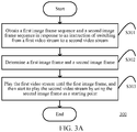
- FIG. 3A is a flowchart of a video play method 300 according to some embodiments of this application.
- the video play method 300 may be performed by the terminal device 110, for example, may be performed by the video play application 111 in the terminal device 110.
- the video play method 300 includes steps S301 to S303.
- step S301 a first image frame sequence and a second image frame sequence are obtained in response to an instruction of switching from a first video stream to a second video stream.
- the first video stream is a currently played video stream.
- the first image frame sequence is from the first video stream, and the second image frame sequence is from the second video stream.
- the first image frame sequence is a plurality of image frames that have not been played by the video play application 111.
- a presentation time stamp (PTS) range of image frames in the first image frame sequence may correspond to a first time interval.
- a PTS range of image frames in the second image frame sequence may correspond to a second time interval.
- a play time of the second image frame sequence may correspond to a play time of the first image frame sequence.
- the corresponding of the play times means that there is an overlap between the first time interval and the second time interval.
- a bitstream of the first video stream is greater than that of the second video stream.
- the video play application 111 may adaptively determine whether to switch between the video streams. When it is detected that a video stream transmission bandwidth is less than a threshold, the video play application 111 may generate the instruction of switching from the first video stream to the second video stream.
- the video play interface may display a check box 302.
- the check box 302 may include, for example, three resolution options: a standard definition option A, a high definition option B, and a super definition option C.
- Each resolution option corresponds to one video stream.
- the standard definition corresponds to the first video stream
- the super definition corresponds to the second video stream.
- the video play application 111 may generate the instruction of switching from the first video stream to the second video stream.
- step S301 a video address, for example, the second index file M 2 , of the second video stream is requested from the content server 220.
- the corresponding second image frame sequence is requested from the content server 220 according to the video address.
- the first image frame sequence may be obtained from the content server 220, and details are not further described herein.
- the media service server 120 may include an index server 121 and a video stream server 122.
- the index server 121 may store video addresses of video streams.
- the video stream server 122 may store image frame sequences of video streams.
- step S301 an access request for the second video stream is sent to the index server 121, so that the index server 121 returns the video address corresponding to the second video stream.
- the video address corresponding to the second video stream may be received, and the second image frame sequence may be obtained from the video stream server 122 according to the video address.
- the first image frame sequence may be obtained from the video stream server 122, and details are not further described herein.
- a first image frame as a switching point in the first image frame sequence and a second image frame matching the first image frame in the second image frame sequence are determined.
- that the first image frame matches the second image frame means that the two image frames match in an image feature aspect.
- a higher matching degree between the first image frame and the second image frame indicates closer capturing time points between the two image frames.
- the capturing time point is a sampling time (which may also be referred to as a shooting time) corresponding to a picture in the image frame.
- the first video stream is played until the first image frame, and then the second video stream starts to be played by using the second image frame as a starting point.
- the second image frame matching the first image frame may be determined based on different proper image matching algorithms.
- the second video stream may be played starting form the second image frame.
- the second video stream may be played starting form an image frame right after the second image frame.
- step S302 the switching point (that is, the first image frame) of the first video stream and the starting point (that is, the second image frame) of the second video stream that match each other may be determined. Because the first image frame matches the second image frame, the method 300 can avoid a problem of picture playback or picture skipping during picture switching in step S303, so that smooth switching can be performed between video stream pictures, thereby improving picture continuity.
- the following describes a process of determining the first image frame and the second image frame by using an example.
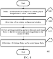
- step S302 may be implemented as a method 400.
- a PTS of a currently played image frame in the first video stream may be obtained, and the PTS is used as a reference PTS.
- a first window and a second window are determined according to the reference PTS.
- the first window belongs to the first image frame sequence.
- the second window belongs to the second image frame sequence.
- an image frame in the first image frame sequence that is spaced by a switching threshold from the reference PTS is determined, the image frame is used as a first reference image frame, and the first window centered on the first reference image frame is determined.
- the first window may include the first reference image frame and one adjacent image frame before (or after) the first reference image frame.
- the first window may include more than two image frames.
- the switching threshold may be a default configured value.
- the switching threshold may be obtained from the media service system 120.
- the media service system 120 may store one or more switching operation records about switching from the first video stream to the second video stream.
- a switching operation record may include a time length or a quantity of frames from a play position (that is, a PTS of a currently played image frame when an instruction of switching to the second video stream is received) to a switching point in the first video stream on the terminal device.
- the media service system 120 may use an average value of time lengths (or quantities of frames) in the one or more switching records as the switching threshold.
- the video play application 111 may obtain, from the media service system 120, the switching threshold determined according to the switching operation records.
- a reference switching point (that is, the first reference image frame) may be determined according to the switching threshold.
- the reference switching point (the first reference image frame) is determined by using the switching threshold determined according to the switching operation records, so that the reference switching point may be closer to a finally determined actual switching point (that is, the first image frame), thereby improving efficiency of determining the switching point.
- an image frame in the second image frame sequence whose PTS is the closest to that of the first reference image frame may be further determined, and the image frame is used as a second reference image frame.
- the second window in the second image frame that is centered on the second reference image frame may be determined.
- the second window may include one or more image frames, which is not limited in this application.
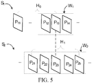
- FIG. 5 shows a process of determining a first window and a second window according to some embodiments of this application.
- a currently displayed image frame in a first image frame sequence S 1 is P 11 .
- PTS 0 that is, a reference PTS, of Pn may be obtained.
- an image frame P 13 that is spaced by a switching threshold Ho from P 11 may be determined, and P 13 is used as a first reference image frame.
- P 13 is in the middle of a first window W 1 .
- the first window W 1 may include, for example, P 12 , P 13 , and P 14 .
- a second reference image frame P 23 may be determined.
- a second window W 2 may be determined.
- the second window W 2 includes a plurality of consecutive image frames in the second image frame sequence, for example, includes P 21 , P 22 , P 23 , P 24 , and P 25 .
- the size of the second window may be, for example, an image frame quantity threshold or a time length threshold, which is not limited in this application.
- step S403 of the method 400 may be performed.
- an image matching operation is performed between each image frame in the first window and each image frame in the second window to determine two image frames having the highest matching degree.
- the image frames in the first window and the second window may be decoded (for example, decoded to be in a format such as YUV), and then the image matching operation is performed according to a histogram of oriented gradient (HOG) algorithm.
- the image matching operation may alternatively be performed by using another proper image matching algorithm, which is not limited in this application.
- a decoding operation may be performed according to dependencies between each image frame and other image frames.
- a to-be-decoded image frame is a predictive frame (P frame)
- decoding may be performed based on an I frame on which the P frame depends, and details are not further described herein.
- step S404 one of the two image frames that belongs to the first window is used as the first image frame, and the other image frame that belongs to the second window is used as the second image frame.
- two corresponding image frame sets (that is, the first window and the second window) may be determined in the first image frame sequence and the second image frame sequence.
- two matching image frames (that is, the first image frame and the second image frame) may be flexibly determined as the switching point and the starting point, to improve continuity between a picture before switching and a picture after switching.
- FIG. 6A is a flowchart of a method 600 for performing step S302 according to some embodiments of this application. As shown in FIG. 6A , the method 600 may include steps S601 to S604. Herein, implementations of steps S601 to S604 are the same as those of steps S401 to S404, and details are not described herein again.
- the method 600 may further include steps S605 and S606.
- step S605 the first window and the second window are slid in a case that a matching degree between the first image frame and the second image frame is less than a matching degree threshold, so that the first image frame is in the middle of the slid first window, and the second image frame is in the middle of the slid window.
- step S606 the first image frame and the second image frame are updated based on the slid first window and the slid second window. Specifically, in step S606, an image matching operation may be performed between each image frame in the slid first window and each image frame in the slid second window to determine two image frames having the highest matching degree.
- step S606 one of the two image frames that belongs to the first window may be used as an updated first image frame, and the other image frame that belongs to the second window may be used as an updated second image frame. Based on this, in the method 600, it may be further determined whether a matching degree between the updated first image frame and the updated second image frame reaches the matching degree threshold. If the matching degree threshold is not reached, steps S605 and S606 of the method 600 may be further performed iteratively until a matching degree reaches the matching degree threshold.
- FIG. 6B is a schematic diagram of the first window and the second window in FIG. 5 after sliding.
- the first window W 1 may include image frames P 13 , P 14 , and P 15
- the second window W 2 includes image frames P 23 , P 24 , P 25 , P 26 , and P 27 .
- step S606 of the method 600 may be performed, to update the first image frame and the second image frame.
- the matching degree between the first image frame and the second image frame may be increased by performing steps S605 and S606, thereby improving picture continuity during picture switching in step S303.
- FIG. 7A is a flowchart of a method 700 for performing step S302 according to some embodiments of this application. As shown in FIG. 7A , the method 700 includes steps S701 to S703. An implementation of step S701 is the same as that of step S401, and details are not described herein again.
- step S702 the first image frame is determined according to the reference PTS, and a window belonging to the second image frame sequence is determined.
- step S702 an image frame in the first image frame sequence that is spaced by a switching threshold from the reference PTS may be determined, and the image frame is used as the first image frame.
- step S702 an image frame in the second image frame sequence whose PTS is the closest to that of the first image frame may be determined, and the image frame is used as a second reference image frame. In this way, in step S702, the window in the second image frame sequence that is centered on the second reference image frame may be determined.
- step S703 an image matching operation is performed between each image frame in the window and the first image frame, to determine an image frame having the highest matching degree with the first image frame in the window, and the image frame is used as the second image frame.
- a currently displayed image frame in a first image frame sequence S 1 is P 11 .
- PTS 0 that is, a reference PTS, of Pn may be obtained.
- an image frame P 13 that is spaced by a switching threshold Ho from PTS 0 may be determined, and P 13 is used as a first image frame.
- a second reference image frame P 23 may be determined.
- a window W 0 may be determined, which may include, for example, P 21 , P 22 , P 23 , P 24 , and P 25 .
- the first image frame may be quickly determined according to the switching threshold, and the second image frame may be selected within a range (that is, the window determined in step S702) in the second image frame sequence that is close to the PTS of the first image frame.
- a range that is, the window determined in step S702
- an image matching degree between the switching point and the starting point may be improved, thereby improving smoothness of picture switching.
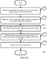
- FIG. 8A is a flowchart of a method 800 for performing step S302 according to some embodiments of this application.
- the method 800 may include steps S801 to S803.
- steps S801 to S803 are the same as those of steps S701 to S703, and details are not described herein again.
- the method 800 may further include steps S804 and S805.
- step S804 the window is slid according to a variation trend of matching degrees corresponding to image frames in the window in a case that a matching degree between the first image frame and the second image frame is less than a matching degree threshold.
- step S805 an image frame having the highest matching degree with the first image frame is determined in the slid window, and the second image frame is updated to the determined image frame.
- step S804 the window is slid forward in a case that the matching degrees corresponding to the image frames in the window increase progressively, that is, a sliding direction is the same as an increasing direction.
- step S804 the window is slid backward in a case that the matching degrees corresponding to the image frames in the window decrease progressively.
- a sliding step length of the window may be determined according to a difference between the matching degree between the first image frame and the second image frame and the matching degree threshold.
- a larger difference corresponds to a larger sliding step length.
- an image frame range of the window may be adjusted based on the variation trend of the matching degrees according to the sliding step length. To explain more vividly, a process of sliding the window is described below by using FIG. 8B and FIG. 8C as examples.
- FIG. 8B is a line graph of a variation trend of matching degrees corresponding to image frames in a window.
- an x-axis indicates a serial number of each image frame
- a y-axis indicates a matching degree.
- a value range of the matching degree is, for example, [0, 1].
- FIG. 8C is a schematic diagram of the window in FIG. 7B after a sliding operation is performed.
- the matching degrees corresponding to the image frames increase progressively in FIG. 8B
- the second image frame in the window in FIG. 7B is P 25 . Therefore, in step S805, the window may be slid forward (that is, in a rightward direction in FIG. 8C ).
- the slid window may include image frames P 26 to P 30 .
- the sliding direction may be determined according to the variation trend of the matching degrees corresponding to the image frames in the second image frame , to accurately update the second image frame, thereby increasing the matching degree between the second image frame and the first image frame.
- a speed of determining the second image frame may be increased, that is, efficiency of determining a starting point is improved.
- FIG. 9 is a flowchart of a method 900 for performing step S302 according to some embodiments of this application.
- the method 900 may include steps S901 to S903.
- steps S901 to S903 are the same as those of steps S701 to S703, and details are not described herein again.
- the method 900 may further include step S904 and step S905.
- step S904 the window is slid in a case that a matching degree between the first image frame and the second image frame is less than a matching degree threshold, so that the second image frame is in the middle of the slid window.
- step S905 an image frame having the highest matching degree with the first image frame is determined in the slid window, and the second image frame is updated to the determined image frame.
- a range of the window can be quickly adjusted and the second image frame can be quickly updated, thereby increasing the matching degree between the switching point and the starting point.
- FIG. 10A is a schematic diagram of a video play apparatus 1000 according to some embodiments of this application.
- the terminal device 110 may include a video play apparatus 1000.
- the video play apparatus 1000 may include an image obtaining unit 1010, a switching control unit 1020, and a video play unit 1030.
- the image obtaining unit 1010 is configured to obtain a first image frame sequence and a second image frame sequence in response to an instruction of switching from a first video stream to a second video stream.
- the first image frame sequence is from the first video stream
- the second image frame sequence is from the second video stream.
- the switching control unit 1020 is configured to determine a first image frame as a switching point in the first image frame sequence and a second image frame matching the first image frame in the second image frame sequence.
- the video play unit 1030 is configured to play the first video stream until the first image frame, and then start to play the second video stream by using the second image frame as a starting point.
- the switching control unit 1020 further includes a window determining module 1021 and an image matching unit 1022.
- the window determining module 1021 is configured to obtain a reference PTS of a currently played image frame in the first video stream upon reception of the instruction. In this way, according to the reference PTS, the window determining module 1021 may determine a first window and a second window.
- the first window belongs to the first image frame sequence.
- the second window belongs to the second image frame sequence.
- the window determining module 1021 may determine an image frame in the first image frame sequence that is spaced by a switching threshold from the reference PTS, use the image frame as a first reference image frame, and determine the first window centered on the first reference image frame. In addition, the window determining module 1021 may determine an image frame in the second image frame sequence whose PTS is the closest to that of the first reference image frame, and use the image frame as a second reference image frame. Based on this, the window determining module 1021 may determine the second window in the second image frame that is centered on the second reference image frame.
- the image matching module 1022 is configured to perform an image matching operation between each image frame in the first window and each image frame in the second window, to determine two image frames having the highest matching degree.
- the image matching module 1022 may use one of the two image frames that belongs to the first window as the first image frame, and use the other image frame that belongs to the second window as the second image frame.
- the window determining module 1021 is further configured to slide the first window and the second window in a case that a matching degree between the first image frame and the second image frame is less than a matching degree threshold, so that the first image frame is in the middle of the slid first window, and the second image frame is in the middle of the slid second window.
- the image matching module 1022 is further configured to update the first image frame and the second image frame according to the slid first window and the slid second window. Specifically, the image matching module 1022 may perform an image matching operation between each image frame in the slid first window and each image frame in the slid second window to determine two image frames having the highest matching degree.
- the image matching module 1022 may use one of the two image frames that belongs to the first window as an updated first image frame, and use the other image frame that belongs to the second window as an updated second image frame. Based on this, the switching control unit 1020 may further determine whether a matching degree between the updated first image frame and the updated second image frame reaches a matching degree threshold by using the window determining module 1021. If the matching degree threshold is not reached, the switching control unit 1020 may further iteratively slide the first window and the second window and update the first image frame and the second image frame until the matching degree reaches the matching degree threshold.
- the switching control unit 1020 further includes a window determining module 1023 and an image matching unit 1024.
- the window determining module 1023 is configured to obtain a reference PTS of a currently played image frame in the first video stream upon reception of the instruction. According to the reference PTS, the window determining module 1023 may determine the first image frame and determine a window belonging to the second image frame sequence. In an embodiment, the window determining module 1023 may determine an image frame in the first image frame sequence that is spaced by a switching threshold from the reference PTS, and use the image frame as the first image frame. In an embodiment, the window determining module 1023 may determine an image frame in the second image frame sequence whose PTS is the closest to that of the first image frame, and use the image frame as a second reference image frame. In this way, the window determining module 1023 may determine the window in the second image frame sequence that is centered on the second reference image frame.
- the image matching module 1024 is configured to perform an image matching operation between each image frame in the window and the first image frame, to determine an image frame having the highest matching degree with the first image frame in the window, and use the image frame as the second image frame.
- the window determining module 1023 is further configured to slide the window according to a variation trend of matching degrees corresponding to image frames in the window in a case that a matching degree between the first image frame and the second image frame is less than a matching degree threshold. In an embodiment, in a case that the matching degrees corresponding to the image frames increase progressively, the window determining module 1023 slides the window forward. In a case that the matching degrees corresponding to the image frames decrease progressively, the window determining module 1023 slides the window backward. In an embodiment, the window determining module 1023 may determine a sliding step length of the window according to a difference between the matching degree between the first image frame and the second image frame and the matching degree threshold.
- the window determining module 1023 may adjust an image frame range of the window according to the sliding step length.
- the image matching module 1024 is further configured to determine an image frame having the highest matching degree with the first image frame in the slid window, and update the second image frame to the determined image frame.
- the window determining module 1023 is further configured to slide the window in a case that a matching degree between the first image frame and the second image frame is less than a matching degree threshold, so that the second image frame is in the middle of the slid window.
- the image matching module is further configured to determine an image frame having the highest matching degree with the first image frame in the slid window, and update the second image frame to the determined image frame.
- the video play apparatus 1000 may determine the switching point (that is, the first image frame) of the first video stream and the starting point (that is, the second image frame) of the second video stream that match each other. Because the first image frame matches the second image frame, the video play apparatus 1000 can avoid a problem of picture playback or picture skipping during picture switching, so that smooth switching can be performed between video stream pictures, thereby improving picture continuity.
- FIG. 11 is a structural diagram of composition of a terminal device.
- the terminal device includes one or more processors (CPUs or GPUs) 1102, a communications module 1104, a memory 1106, a user interface 1110, and a communications bus 1108 for connecting the components.
- the processor 1102 may receive and send data by using the communications module 1104 to implement network communication and/or local communication.
- the user interface 1110 includes one or more output devices 1112, including one or more speakers and/or one or more visualization displays.
- the user interface 1110 further includes one or more input devices 1114, including, for example, a keyboard, a mouse, a sound command input unit or a microphone, a touch display, a touch-sensitive input panel, a posture capturing camera, or another input key or control.
- the memory 1106 may be a high-speed random access memory (RAM) such as a DRAM, an SRAM, a DDR RAM, or another random access solid-state memory device; or a non-volatile memory such as one or more magnetic disk storage devices, optical disk storage devices, flash memory devices, or other non-volatile solid-state memory devices.
- RAM random access memory
- SRAM SRAM
- DDR RAM DDR RAM
- non-volatile memory such as one or more magnetic disk storage devices, optical disk storage devices, flash memory devices, or other non-volatile solid-state memory devices.
- the memory 1106 stores an instruction set that can be executed by the processor 1102 and includes:
- each embodiment of this application may be implemented by a data processing program executed by a data processing device such as a computer.
- the data processing program constitutes this application.
- a data processing program stored in a storage medium is directly read from the storage medium for execution or the program is installed on or replicated to a storage device (such as a hard disk or an internal memory) of a data processing device for execution. Therefore, such a storage medium also constitutes the present invention.
- the storage medium may use any recording manner, for example, a paper storage medium (such as paper tape), a magnetic storage medium (such as a floppy disk, a hard disk, and a flash memory), an optical storage medium (such as a CD-ROM), and a magneto-optical storage medium (such as an MO).
- a paper storage medium such as paper tape
- a magnetic storage medium such as a floppy disk, a hard disk, and a flash memory
- an optical storage medium such as a CD-ROM
- a magneto-optical storage medium such as an MO
- this application further discloses a non-volatile storage medium, which stores a data processing program.
- the data processing program is configured to perform any embodiment of the foregoing video play method of this application.
- the steps of the method of this application may be implemented not only by the data processing program, but also by hardware, such as a logic gate, a switch, an application-specific integrated circuit (ASIC), a programmable logic controller, and an embedded microcontroller. Therefore, the hardware that may implement the method of this application may also constitute this application.
- hardware such as a logic gate, a switch, an application-specific integrated circuit (ASIC), a programmable logic controller, and an embedded microcontroller. Therefore, the hardware that may implement the method of this application may also constitute this application.
Landscapes
- Engineering & Computer Science (AREA)
- Multimedia (AREA)
- Signal Processing (AREA)
- Databases & Information Systems (AREA)
- Human Computer Interaction (AREA)
- Computer Security & Cryptography (AREA)
- Marketing (AREA)
- Business, Economics & Management (AREA)
- Two-Way Televisions, Distribution Of Moving Picture Or The Like (AREA)
- Television Signal Processing For Recording (AREA)
- Computer Vision & Pattern Recognition (AREA)
- Physics & Mathematics (AREA)
- General Physics & Mathematics (AREA)
- Theoretical Computer Science (AREA)
- Compression Or Coding Systems Of Tv Signals (AREA)
Abstract
Description
- This application claims priority to Chinese Patent Application No.
201810101152.9 - This application relates to the field of video play, and in particular, to a video play method, a terminal device, and a storage medium.
- With the development of multimedia technologies, a user may play video content by using different computing devices. The video content may be transcoded into a plurality of bitstreams for the user to select. During bitstream switching, in an existing solution, a new file slice or an intra frame (I frame) in a target video stream is usually selected and played. However, a problem such as picture skipping exists during bitstream switching in the existing solution.
- This application provides a video play solution, to improve picture continuity during bitstream switching.
- According to an aspect of this application, a video play method is provided, including: obtaining a first image frame sequence and a second image frame sequence in response to an instruction of switching from a first video stream to a second video stream, the first image frame sequence being from the first video stream, and the second image frame sequence being from the second video stream; determining a first image frame as a switching point in the first image frame sequence and a second image frame matching the first image frame in the second image frame sequence; and playing the first video stream until the first image frame, and then starting to play the second video stream by using the second image frame as a starting point.
- According to an aspect of this application, a terminal device is provided, including: one or more processors, a memory, and one or more programs. The programs are stored in the memory and configured to be executed by the one or more processors, the one or more programs including instructions used for performing the video play method of this application.
- According to an aspect of this application, a storage medium is provided, storing one or more programs. The one or more programs include instructions. The instructions, when executed by a terminal device, cause the terminal device to perform the video play method of this application.
- In conclusion, in the video play solution of this application, the switching point (that is, the first image frame) of the first video stream and the starting point (that is, the second image frame) of the second video stream can be determined. Because the first image frame matches the second image frame, the video play solution can avoid a problem of picture playback or picture skipping during picture switching, so that smooth switching can be performed between video stream pictures, thereby improving picture continuity.
- To describe the technical solutions in embodiments of this application more clearly, the following briefly describes the accompanying drawings required for describing the embodiments. Apparently, the accompanying drawings in the following description show merely some embodiments of this application, and a person of ordinary skill in the art may derive other drawings from these accompanying drawings without creative efforts.
-
FIG. 1 is a schematic diagram of an application scenario 100 according to some embodiments of this application. -
FIG. 2 is a schematic diagram of amedia service system 120 according to some embodiments of this application. -
FIG. 3A is a flowchart of avideo play method 300 according to some embodiments of this application. -
FIG. 3B is a video play interface according to an embodiment of this application. -
FIG. 3C is a schematic diagram of amedia service system 120 according to an embodiment of this application. -
FIG. 4 is a flowchart of amethod 400 for performing step S302 according to some embodiments of this application. -
FIG. 5 is a schematic diagram of a first window and a second window according to some embodiments of this application. -
FIG. 6A is a flowchart of amethod 600 for performing step S302 according to some embodiments of this application. -
FIG. 6B is a schematic diagram of the first window and the second window inFIG. 5 after sliding. -
FIG. 7A is a flowchart of amethod 700 for performing step S302 according to some embodiments of this application. -
FIG. 7B is a schematic diagram of a determined window according to an embodiment of this application. -
FIG. 8A is a flowchart of amethod 800 for performing step S302 according to some embodiments of this application. -
FIG. 8B is a line graph of a variation trend according to an embodiment of this application. -
FIG. 8C is a schematic diagram of the window inFIG. 7B after a sliding operation is performed. -
FIG. 9 is a flowchart of amethod 900 for performing step S302 according to some embodiments of this application. -
FIG. 10A is a schematic diagram of a video play apparatus 1000 according to some embodiments of this application. -
FIG. 10B is a structural diagram of a switching control unit according to some embodiments of this application. -
FIG. 10C is a structural diagram of a switching control unit according to some embodiments of this application. -
FIG. 11 is a structural diagram of composition of a terminal device. - The technical solutions in the embodiments of this application will be clearly and completely described in the following with reference to the accompanying drawings in the embodiments of this application. It is obvious that the embodiments to be described are only some rather than all of the embodiments of this application. All other embodiments obtained by a person of ordinary skill in the art based on the embodiments of this application without creative efforts shall fall within the protection scope of this application.
- The technical solutions in the embodiments of this application will be clearly and completely described in the following with reference to the accompanying drawings in the embodiments of this application. It is obvious that the embodiments to be described are only some rather than all of the embodiments of this application. All other embodiments obtained by a person of ordinary skill in the art based on the embodiments of this application without creative efforts shall fall within the protection scope of this application.
-
FIG. 1 is a schematic diagram of an application scenario 100 according to some embodiments of this application. As shown inFIG. 1 , the application scenario 100 may include aterminal device 110 and amedia service system 120. Theterminal device 110 may be different intelligent devices such as a mobile phone, a desktop computer, a laptop, a TV box, a projection device, a head-mounted display device, or a tablet computer. Theterminal device 110 may include avideo play application 111. Herein, thevideo play application 111 may be, for example, a video client (for example, Tencent Video client or Youku Video client), a social application capable of playing a video, or a browser, which is not limited in this application. Themedia service system 120 may include one or more servers, and provide video content to theterminal device 110 through anetwork 130. The video content herein may be a video on demand or a live video. Themedia service system 120 may generate video data in different data formats by using one piece of video content. In other words, one piece of video content may correspond to a plurality of pieces of video data. For example, the data formats may be classified based on one or more of parameters such as a frame rate, a bit rate, and a resolution. Using the resolution as an example, a range of the data formats may include standard definition, high definition, super definition, and the like. In addition, themedia service system 120 may transmit the video data to theterminal device 110 in a stream form. The video data transmitted in the stream form may be referred to as a video stream. For a piece of video content, theterminal device 110 may request one or more video streams of the video content from themedia service system 120. -
FIG. 2 is a schematic diagram of amedia service system 120 according to some embodiments of this application. As shown inFIG. 2 , themedia service system 120 may include atranscoding server 210 and acontent server 220. Thetranscoding server 210 may include anencoding unit 211 and aslicing unit 212. Theencoding unit 211 may encode media content, to generate video data in a plurality of formats corresponding to the media content. For example, theencoding unit 211 herein may perform encoding based on the second of several standards developed by the Moving Pictures Expert Group (MPEG-2), but this application is not limited hereto. Theslicing unit 212 may slice video data to obtain a corresponding slice file and index file. The index file is, for example, in a format of M3U8. The slice file is, for example, in a format of a transport stream (TS) slice. Thecontent server 220 may include the slice file and the index file of the video data. Thecontent server 220 may provide the index file to theterminal device 110, so that theterminal device 110 requests, from thecontent server 220 according to the index file, a slice file corresponding to the index file. In an embodiment, for a piece of video content, thecontent server 220 may provide two video streams to the terminal device 110: afirst video stream 221 and asecond video stream 222. Thefirst video stream 221 may include a first index file M1 and a first slice file TSi. Thesecond video stream 222 may include a second index file M2 and a second slice file TS2. Thecontent server 220 further includes anindex service unit 223. Theindex service unit 223 may send, to theterminal device 110 according to a request of theterminal device 110 for a video stream, an index file corresponding to the video stream. For example, theindex service unit 223 may send the first index file M1 to theterminal device 110. In this way, theterminal device 110 may request the first slice file TS1 from thecontent server 220 according to the first index file M1. In an embodiment, thecontent server 220 may include an index server and a video stream server (not shown inFIG. 2 ). Theterminal device 110 may send an access request for a video stream to the index server, so that the index server returns a video address (that is, an index file) corresponding to the video stream. Theterminal device 110 may receive the video address, and obtain an image frame sequence from the video stream server according to the video address. -
FIG. 3A is a flowchart of avideo play method 300 according to some embodiments of this application. Thevideo play method 300 may be performed by theterminal device 110, for example, may be performed by thevideo play application 111 in theterminal device 110. - As shown in
FIG. 3A , thevideo play method 300 includes steps S301 to S303. In step S301, a first image frame sequence and a second image frame sequence are obtained in response to an instruction of switching from a first video stream to a second video stream. The first video stream is a currently played video stream. The first image frame sequence is from the first video stream, and the second image frame sequence is from the second video stream. Herein, the first image frame sequence is a plurality of image frames that have not been played by thevideo play application 111. - In an embodiment, a presentation time stamp (PTS) range of image frames in the first image frame sequence may correspond to a first time interval. Similarly, a PTS range of image frames in the second image frame sequence may correspond to a second time interval. A play time of the second image frame sequence may correspond to a play time of the first image frame sequence. Herein, the corresponding of the play times means that there is an overlap between the first time interval and the second time interval.
- In an embodiment, a bitstream of the first video stream is greater than that of the second video stream. The
video play application 111 may adaptively determine whether to switch between the video streams. When it is detected that a video stream transmission bandwidth is less than a threshold, thevideo play application 111 may generate the instruction of switching from the first video stream to the second video stream. - According to an embodiment, in a video play interface shown in
FIG. 3B , when a user clicks/taps abutton 301, the video play interface may display acheck box 302. Thecheck box 302 may include, for example, three resolution options: a standard definition option A, a high definition option B, and a super definition option C. Each resolution option corresponds to one video stream. For example, the standard definition corresponds to the first video stream, and the super definition corresponds to the second video stream. When the currently played video stream is in a standard definition format and the user clicks/taps the super definition option C in the check box, thevideo play application 111 may generate the instruction of switching from the first video stream to the second video stream. - According to an embodiment, in step S301, a video address, for example, the second index file M2, of the second video stream is requested from the
content server 220. When the video address is received, in step S301, the corresponding second image frame sequence is requested from thecontent server 220 according to the video address. Similarly, in step S301, the first image frame sequence may be obtained from thecontent server 220, and details are not further described herein. - As shown in
FIG. 3C , in an embodiment, themedia service server 120 may include anindex server 121 and avideo stream server 122. Theindex server 121 may store video addresses of video streams. Thevideo stream server 122 may store image frame sequences of video streams. In step S301, an access request for the second video stream is sent to theindex server 121, so that theindex server 121 returns the video address corresponding to the second video stream. Based on this, in step S301, the video address corresponding to the second video stream may be received, and the second image frame sequence may be obtained from thevideo stream server 122 according to the video address. Similarly, in step S301, the first image frame sequence may be obtained from thevideo stream server 122, and details are not further described herein. - In step S302, a first image frame as a switching point in the first image frame sequence and a second image frame matching the first image frame in the second image frame sequence are determined. Herein, that the first image frame matches the second image frame means that the two image frames match in an image feature aspect. In some embodiments, a higher matching degree between the first image frame and the second image frame indicates closer capturing time points between the two image frames. The capturing time point is a sampling time (which may also be referred to as a shooting time) corresponding to a picture in the image frame. In step S303, the first video stream is played until the first image frame, and then the second video stream starts to be played by using the second image frame as a starting point. Herein, in step S302, the second image frame matching the first image frame may be determined based on different proper image matching algorithms. In an embodiment, in step S303, the second video stream may be played starting form the second image frame. In an embodiment, in step S303, the second video stream may be played starting form an image frame right after the second image frame.
- In an application scenario of video stream switching, frame rates of different video streams may be different. Therefore, PTSs of image frames of different video streams usually cannot accurately correspond to each other. In other words, the
video play application 111 usually cannot perform smooth switching between two video streams directly according to PTSs. In themethod 300, by performing step S302, the switching point (that is, the first image frame) of the first video stream and the starting point (that is, the second image frame) of the second video stream that match each other may be determined. Because the first image frame matches the second image frame, themethod 300 can avoid a problem of picture playback or picture skipping during picture switching in step S303, so that smooth switching can be performed between video stream pictures, thereby improving picture continuity. The following describes a process of determining the first image frame and the second image frame by using an example. - In an embodiment, step S302 may be implemented as a
method 400. As shown inFIG. 4 , when the instruction of switching to the second video stream is received, in step S401, a PTS of a currently played image frame in the first video stream may be obtained, and the PTS is used as a reference PTS. - In step S402, a first window and a second window are determined according to the reference PTS. The first window belongs to the first image frame sequence. The second window belongs to the second image frame sequence. According to an embodiment, in step S402, an image frame in the first image frame sequence that is spaced by a switching threshold from the reference PTS is determined, the image frame is used as a first reference image frame, and the first window centered on the first reference image frame is determined. Herein, when the first window includes two image frames, the first window may include the first reference image frame and one adjacent image frame before (or after) the first reference image frame. Alternatively, the first window may include more than two image frames. In an embodiment, the switching threshold may be a default configured value. In an embodiment, the switching threshold may be obtained from the
media service system 120. Herein, themedia service system 120 may store one or more switching operation records about switching from the first video stream to the second video stream. A switching operation record may include a time length or a quantity of frames from a play position (that is, a PTS of a currently played image frame when an instruction of switching to the second video stream is received) to a switching point in the first video stream on the terminal device. In this way, themedia service system 120 may use an average value of time lengths (or quantities of frames) in the one or more switching records as the switching threshold. For example, when step S301 is performed, thevideo play application 111 may obtain, from themedia service system 120, the switching threshold determined according to the switching operation records. In this way, in step S402, a reference switching point (that is, the first reference image frame) may be determined according to the switching threshold. Herein, in step S402, the reference switching point (the first reference image frame) is determined by using the switching threshold determined according to the switching operation records, so that the reference switching point may be closer to a finally determined actual switching point (that is, the first image frame), thereby improving efficiency of determining the switching point. Based on the determined first reference image frame, in step S402, an image frame in the second image frame sequence whose PTS is the closest to that of the first reference image frame may be further determined, and the image frame is used as a second reference image frame. In this way, in step S402, the second window in the second image frame that is centered on the second reference image frame may be determined. Herein, the second window may include one or more image frames, which is not limited in this application. -
FIG. 5 shows a process of determining a first window and a second window according to some embodiments of this application. As shown inFIG. 5 , a currently displayed image frame in a first image frame sequence S1 is P11. In step S401, PTS0, that is, a reference PTS, of Pn may be obtained. In step S402, an image frame P13 that is spaced by a switching threshold Ho from P11 may be determined, and P13 is used as a first reference image frame. P13 is in the middle of a first window W1. The first window W1 may include, for example, P12, P13, and P14. - For a second image frame sequence S2, in step S402, a second reference image frame P23 may be determined. According to a size H1 of the second window, in step S402, a second window W2 may be determined. Herein, the second window W2 includes a plurality of consecutive image frames in the second image frame sequence, for example, includes P21, P22, P23, P24, and P25. The size of the second window may be, for example, an image frame quantity threshold or a time length threshold, which is not limited in this application.
- Based on the first window and the second window determined in step S402, step S403 of the
method 400 may be performed. In step S403, an image matching operation is performed between each image frame in the first window and each image frame in the second window to determine two image frames having the highest matching degree. In an embodiment, in step S403, the image frames in the first window and the second window may be decoded (for example, decoded to be in a format such as YUV), and then the image matching operation is performed according to a histogram of oriented gradient (HOG) algorithm. Herein, in step S403, the image matching operation may alternatively be performed by using another proper image matching algorithm, which is not limited in this application. In addition, in step S403, when the first image frame and the second image frame are decoded, a decoding operation may be performed according to dependencies between each image frame and other image frames. For example, a to-be-decoded image frame is a predictive frame (P frame), then in step S403, decoding may be performed based on an I frame on which the P frame depends, and details are not further described herein. - In step S404, one of the two image frames that belongs to the first window is used as the first image frame, and the other image frame that belongs to the second window is used as the second image frame.
- In conclusion, in the
method 400, two corresponding image frame sets (that is, the first window and the second window) may be determined in the first image frame sequence and the second image frame sequence. Based on this, in themethod 400, two matching image frames (that is, the first image frame and the second image frame) may be flexibly determined as the switching point and the starting point, to improve continuity between a picture before switching and a picture after switching. -
FIG. 6A is a flowchart of amethod 600 for performing step S302 according to some embodiments of this application. As shown inFIG. 6A , themethod 600 may include steps S601 to S604. Herein, implementations of steps S601 to S604 are the same as those of steps S401 to S404, and details are not described herein again. - In addition, the
method 600 may further include steps S605 and S606. In step S605, the first window and the second window are slid in a case that a matching degree between the first image frame and the second image frame is less than a matching degree threshold, so that the first image frame is in the middle of the slid first window, and the second image frame is in the middle of the slid window. In step S606, the first image frame and the second image frame are updated based on the slid first window and the slid second window. Specifically, in step S606, an image matching operation may be performed between each image frame in the slid first window and each image frame in the slid second window to determine two image frames having the highest matching degree. Based on this, in step S606, one of the two image frames that belongs to the first window may be used as an updated first image frame, and the other image frame that belongs to the second window may be used as an updated second image frame. Based on this, in themethod 600, it may be further determined whether a matching degree between the updated first image frame and the updated second image frame reaches the matching degree threshold. If the matching degree threshold is not reached, steps S605 and S606 of themethod 600 may be further performed iteratively until a matching degree reaches the matching degree threshold. - Using
FIG. 5 as an example, the first image frame determined in step S604 is P14, and the second image frame is P25.FIG. 6B is a schematic diagram of the first window and the second window inFIG. 5 after sliding. As shown inFIG. 6B , after the first window and the second window are slid in step S605, the first window W1 may include image frames P13, P14, and P15, and the second window W2 includes image frames P23, P24, P25, P26, and P27. For the slid first window and the second window, step S606 of themethod 600 may be performed, to update the first image frame and the second image frame. - In conclusion, in the
method 600, the matching degree between the first image frame and the second image frame may be increased by performing steps S605 and S606, thereby improving picture continuity during picture switching in step S303. -
FIG. 7A is a flowchart of amethod 700 for performing step S302 according to some embodiments of this application. As shown inFIG. 7A , themethod 700 includes steps S701 to S703. An implementation of step S701 is the same as that of step S401, and details are not described herein again. - In step S702, the first image frame is determined according to the reference PTS, and a window belonging to the second image frame sequence is determined. In an embodiment, in step S702, an image frame in the first image frame sequence that is spaced by a switching threshold from the reference PTS may be determined, and the image frame is used as the first image frame. In an embodiment, in step S702, an image frame in the second image frame sequence whose PTS is the closest to that of the first image frame may be determined, and the image frame is used as a second reference image frame. In this way, in step S702, the window in the second image frame sequence that is centered on the second reference image frame may be determined.
- In step S703, an image matching operation is performed between each image frame in the window and the first image frame, to determine an image frame having the highest matching degree with the first image frame in the window, and the image frame is used as the second image frame.
- To explain more vividly, the following describes a process of determining the window by using
FIG. 7B as an example. As shown inFIG. 7B , a currently displayed image frame in a first image frame sequence S1 is P11. In step S701, PTS0, that is, a reference PTS, of Pn may be obtained. In step S702, an image frame P13 that is spaced by a switching threshold Ho from PTS0 may be determined, and P13 is used as a first image frame. For a second image frame sequence S2, in step S702, a second reference image frame P23 may be determined. According to a size H1 of the window, in step S702, a window W0 may be determined, which may include, for example, P21, P22, P23, P24, and P25. - In conclusion, in the
method 700, the first image frame may be quickly determined according to the switching threshold, and the second image frame may be selected within a range (that is, the window determined in step S702) in the second image frame sequence that is close to the PTS of the first image frame. In this way, in themethod 700, through a matching operation between the first image frame and each image frame within the range, an image matching degree between the switching point and the starting point may be improved, thereby improving smoothness of picture switching. -
FIG. 8A is a flowchart of amethod 800 for performing step S302 according to some embodiments of this application. As shown inFIG. 8A , themethod 800 may include steps S801 to S803. Herein, implementations of steps S801 to S803 are the same as those of steps S701 to S703, and details are not described herein again. In addition, themethod 800 may further include steps S804 and S805. - In step S804, the window is slid according to a variation trend of matching degrees corresponding to image frames in the window in a case that a matching degree between the first image frame and the second image frame is less than a matching degree threshold. In step S805, an image frame having the highest matching degree with the first image frame is determined in the slid window, and the second image frame is updated to the determined image frame.
- In some embodiments, in step S804, the window is slid forward in a case that the matching degrees corresponding to the image frames in the window increase progressively, that is, a sliding direction is the same as an increasing direction. In step S804, the window is slid backward in a case that the matching degrees corresponding to the image frames in the window decrease progressively. In an embodiment, in step S804, a sliding step length of the window may be determined according to a difference between the matching degree between the first image frame and the second image frame and the matching degree threshold. Herein, a larger difference corresponds to a larger sliding step length. In this way, in step S804, an image frame range of the window may be adjusted based on the variation trend of the matching degrees according to the sliding step length. To explain more vividly, a process of sliding the window is described below by using
FIG. 8B and FIG. 8C as examples. -
FIG. 8B is a line graph of a variation trend of matching degrees corresponding to image frames in a window. As shown inFIG. 8B , an x-axis indicates a serial number of each image frame, and a y-axis indicates a matching degree. Herein, a value range of the matching degree is, for example, [0, 1].FIG. 8C is a schematic diagram of the window inFIG. 7B after a sliding operation is performed. The matching degrees corresponding to the image frames increase progressively inFIG. 8B , and the second image frame in the window inFIG. 7B is P25. Therefore, in step S805, the window may be slid forward (that is, in a rightward direction inFIG. 8C ). As shown inFIG. 8C , the slid window may include image frames P26 to P30. - In conclusion, in the
method 800, the sliding direction may be determined according to the variation trend of the matching degrees corresponding to the image frames in the second image frame , to accurately update the second image frame, thereby increasing the matching degree between the second image frame and the first image frame. In addition, in themethod 800, by dynamically adjusting the sliding step length, a speed of determining the second image frame may be increased, that is, efficiency of determining a starting point is improved. -
FIG. 9 is a flowchart of amethod 900 for performing step S302 according to some embodiments of this application. As shown inFIG. 9 , themethod 900 may include steps S901 to S903. Herein, implementations of steps S901 to S903 are the same as those of steps S701 to S703, and details are not described herein again. Themethod 900 may further include step S904 and step S905. - In step S904, the window is slid in a case that a matching degree between the first image frame and the second image frame is less than a matching degree threshold, so that the second image frame is in the middle of the slid window.
- In step S905, an image frame having the highest matching degree with the first image frame is determined in the slid window, and the second image frame is updated to the determined image frame.
- In conclusion, in the
method 900, by keeping the second image frame in the middle of the slid window, a range of the window can be quickly adjusted and the second image frame can be quickly updated, thereby increasing the matching degree between the switching point and the starting point. -
FIG. 10A is a schematic diagram of a video play apparatus 1000 according to some embodiments of this application. Theterminal device 110 may include a video play apparatus 1000. As shown inFIG. 10 , the video play apparatus 1000 may include animage obtaining unit 1010, a switchingcontrol unit 1020, and avideo play unit 1030. - The
image obtaining unit 1010 is configured to obtain a first image frame sequence and a second image frame sequence in response to an instruction of switching from a first video stream to a second video stream. The first image frame sequence is from the first video stream, and the second image frame sequence is from the second video stream. - The switching
control unit 1020 is configured to determine a first image frame as a switching point in the first image frame sequence and a second image frame matching the first image frame in the second image frame sequence. - The
video play unit 1030 is configured to play the first video stream until the first image frame, and then start to play the second video stream by using the second image frame as a starting point. - As shown in
FIG. 10B , in some embodiments, the switchingcontrol unit 1020 further includes awindow determining module 1021 and animage matching unit 1022. Thewindow determining module 1021 is configured to obtain a reference PTS of a currently played image frame in the first video stream upon reception of the instruction. In this way, according to the reference PTS, thewindow determining module 1021 may determine a first window and a second window. The first window belongs to the first image frame sequence. The second window belongs to the second image frame sequence. - In an embodiment, the
window determining module 1021 may determine an image frame in the first image frame sequence that is spaced by a switching threshold from the reference PTS, use the image frame as a first reference image frame, and determine the first window centered on the first reference image frame. In addition, thewindow determining module 1021 may determine an image frame in the second image frame sequence whose PTS is the closest to that of the first reference image frame, and use the image frame as a second reference image frame. Based on this, thewindow determining module 1021 may determine the second window in the second image frame that is centered on the second reference image frame. - The
image matching module 1022 is configured to perform an image matching operation between each image frame in the first window and each image frame in the second window, to determine two image frames having the highest matching degree. Theimage matching module 1022 may use one of the two image frames that belongs to the first window as the first image frame, and use the other image frame that belongs to the second window as the second image frame. - In an embodiment, the
window determining module 1021 is further configured to slide the first window and the second window in a case that a matching degree between the first image frame and the second image frame is less than a matching degree threshold, so that the first image frame is in the middle of the slid first window, and the second image frame is in the middle of the slid second window. Theimage matching module 1022 is further configured to update the first image frame and the second image frame according to the slid first window and the slid second window. Specifically, theimage matching module 1022 may perform an image matching operation between each image frame in the slid first window and each image frame in the slid second window to determine two image frames having the highest matching degree. Based on this, theimage matching module 1022 may use one of the two image frames that belongs to the first window as an updated first image frame, and use the other image frame that belongs to the second window as an updated second image frame. Based on this, the switchingcontrol unit 1020 may further determine whether a matching degree between the updated first image frame and the updated second image frame reaches a matching degree threshold by using thewindow determining module 1021. If the matching degree threshold is not reached, the switchingcontrol unit 1020 may further iteratively slide the first window and the second window and update the first image frame and the second image frame until the matching degree reaches the matching degree threshold. - As shown in
FIG. 10C , in some embodiments, the switchingcontrol unit 1020 further includes awindow determining module 1023 and an image matching unit 1024. - The
window determining module 1023 is configured to obtain a reference PTS of a currently played image frame in the first video stream upon reception of the instruction. According to the reference PTS, thewindow determining module 1023 may determine the first image frame and determine a window belonging to the second image frame sequence. In an embodiment, thewindow determining module 1023 may determine an image frame in the first image frame sequence that is spaced by a switching threshold from the reference PTS, and use the image frame as the first image frame. In an embodiment, thewindow determining module 1023 may determine an image frame in the second image frame sequence whose PTS is the closest to that of the first image frame, and use the image frame as a second reference image frame. In this way, thewindow determining module 1023 may determine the window in the second image frame sequence that is centered on the second reference image frame. - The image matching module 1024 is configured to perform an image matching operation between each image frame in the window and the first image frame, to determine an image frame having the highest matching degree with the first image frame in the window, and use the image frame as the second image frame.
- In some embodiments, the
window determining module 1023 is further configured to slide the window according to a variation trend of matching degrees corresponding to image frames in the window in a case that a matching degree between the first image frame and the second image frame is less than a matching degree threshold. In an embodiment, in a case that the matching degrees corresponding to the image frames increase progressively, thewindow determining module 1023 slides the window forward. In a case that the matching degrees corresponding to the image frames decrease progressively, thewindow determining module 1023 slides the window backward. In an embodiment, thewindow determining module 1023 may determine a sliding step length of the window according to a difference between the matching degree between the first image frame and the second image frame and the matching degree threshold. Based on the variation trend of the matching degrees, thewindow determining module 1023 may adjust an image frame range of the window according to the sliding step length. The image matching module 1024 is further configured to determine an image frame having the highest matching degree with the first image frame in the slid window, and update the second image frame to the determined image frame. - In some embodiments, the
window determining module 1023 is further configured to slide the window in a case that a matching degree between the first image frame and the second image frame is less than a matching degree threshold, so that the second image frame is in the middle of the slid window. The image matching module is further configured to determine an image frame having the highest matching degree with the first image frame in the slid window, and update the second image frame to the determined image frame. A more specific implementation of the video play apparatus 1000 is the same as that of thevideo play method 300, and details are not described herein again. - In conclusion, the video play apparatus 1000 may determine the switching point (that is, the first image frame) of the first video stream and the starting point (that is, the second image frame) of the second video stream that match each other. Because the first image frame matches the second image frame, the video play apparatus 1000 can avoid a problem of picture playback or picture skipping during picture switching, so that smooth switching can be performed between video stream pictures, thereby improving picture continuity.
-
FIG. 11 is a structural diagram of composition of a terminal device. As shown inFIG. 11 , the terminal device includes one or more processors (CPUs or GPUs) 1102, acommunications module 1104, amemory 1106, a user interface 1110, and acommunications bus 1108 for connecting the components. - The
processor 1102 may receive and send data by using thecommunications module 1104 to implement network communication and/or local communication. - The user interface 1110 includes one or
more output devices 1112, including one or more speakers and/or one or more visualization displays. The user interface 1110 further includes one ormore input devices 1114, including, for example, a keyboard, a mouse, a sound command input unit or a microphone, a touch display, a touch-sensitive input panel, a posture capturing camera, or another input key or control. - The
memory 1106 may be a high-speed random access memory (RAM) such as a DRAM, an SRAM, a DDR RAM, or another random access solid-state memory device; or a non-volatile memory such as one or more magnetic disk storage devices, optical disk storage devices, flash memory devices, or other non-volatile solid-state memory devices. - The
memory 1106 stores an instruction set that can be executed by theprocessor 1102 and includes: - an
operating system 1116, including a program for processing basic system services and for executing hardware-related tasks; and - an
application 1118, including programs for implementing the video play method, where the program can implement the processing procedures in the foregoing embodiments, for example, theapplication 1118 may include the video play apparatus 1000 shown inFIG. 10 . - In addition, each embodiment of this application may be implemented by a data processing program executed by a data processing device such as a computer. Apparently, the data processing program constitutes this application. In addition, generally, a data processing program stored in a storage medium is directly read from the storage medium for execution or the program is installed on or replicated to a storage device (such as a hard disk or an internal memory) of a data processing device for execution. Therefore, such a storage medium also constitutes the present invention. The storage medium may use any recording manner, for example, a paper storage medium (such as paper tape), a magnetic storage medium (such as a floppy disk, a hard disk, and a flash memory), an optical storage medium (such as a CD-ROM), and a magneto-optical storage medium (such as an MO).
- Therefore, this application further discloses a non-volatile storage medium, which stores a data processing program. The data processing program is configured to perform any embodiment of the foregoing video play method of this application.
- In addition, the steps of the method of this application may be implemented not only by the data processing program, but also by hardware, such as a logic gate, a switch, an application-specific integrated circuit (ASIC), a programmable logic controller, and an embedded microcontroller. Therefore, the hardware that may implement the method of this application may also constitute this application.
- The foregoing descriptions are merely exemplary embodiments of this application, but are not intended to limit this application. Any modification, equivalent replacement, or improvement made within the spirit and principle of this application shall fall within the protection scope of this application.
Claims (13)
- A video play method, performed by a terminal device, the method comprising:obtaining a first image frame sequence and a second image frame sequence in response to an instruction of switching from a first video stream to a second video stream, the first image frame sequence being from the first video stream, and the second image frame sequence being from the second video stream;determining a first image frame as a switching point in the first image frame sequence and a second image frame matching the first image frame in the second image frame sequence; andplaying the first video stream until the first image frame, and then starting to play the second video stream by using the second image frame as a starting point.
- The method according to claim 1, wherein the determining a first image frame as a switching point in the first image frame sequence and a second image frame matching the first image frame in the second image frame sequence comprises:obtaining a reference presentation time stamp (PTS) of a currently played image frame in the first video stream upon reception of the instruction;determining a first window and a second window according to the reference PTS, the first window belonging to the first image frame sequence, and the second window belonging to the second image frame sequence;performing an image matching operation between each image frame in the first window and each image frame in the second window, to determine two image frames having the highest matching degree; andusing one of the two image frames that belongs to the first window as the first image frame, and using the other image frame that belongs to the second window as the second image frame.
- The method according to claim 2, wherein the determining a first window and a second window according to the reference PTS comprises:determining an image frame in the first image frame sequence that is spaced by a switching threshold from the reference PTS, using the image frame as a first reference image frame, and determining the first window centered on the first reference image frame;determining an image frame in the second image frame sequence whose PTS is the closest to that of the first reference image frame, and using the image frame as a second reference image frame; anddetermining the second window in the second image frame that is centered on the second reference image frame.
- The method according to claim 2, further comprising:sliding the first window and the second window in a case that a matching degree between the first image frame and the second image frame is less than a matching degree threshold, so that the first image frame is in the middle of the slid first window, and the second image frame is in the middle of the slid second window; andupdating the first image frame and the second image frame based on the slid first window and the slid second window.
- The method according to claim 1, wherein the determining a first image frame as a switching point in the first image frame sequence and a second image frame matching the first image frame in the second image frame sequence comprises:obtaining a reference PTS of a currently played image frame in the first video stream upon reception of the instruction;determining the first image frame according to the reference PTS, and determining a window belonging to the second image frame sequence; andperforming an image matching operation between each image frame in the window and the first image frame, to determine an image frame having the highest matching degree with the first image frame in the window, and using the image frame as the second image frame.
- The method according to claim 5, wherein the determining the first image frame according to the reference PTS comprises:
determining an image frame in the first image frame sequence that is spaced by a switching threshold from the reference PTS, and using the image frame as the first image frame. - The method according to claim 5, wherein the determining the first image frame according to the reference PTS, and determining a window belonging to the second image frame sequence comprises:determining an image frame in the second image frame sequence whose PTS is the closest to that of the first image frame, and using the image frame as a second reference image frame; anddetermining the window in the second image frame sequence that is centered on the second reference image frame.
- The method according to claim 5, further comprising:sliding the window according to a variation trend of matching degrees corresponding to image frames in the window in a case that a matching degree between the first image frame and the second image frame is less than a matching degree threshold; anddetermining an image frame having the highest matching degree with the first image frame in the slid window, and updating the second image frame to the determined image frame.
- The method according to claim 8, wherein the sliding the window according to a variation trend of matching degrees corresponding to image frames in the window comprises:sliding the window forward in a case that the matching degrees corresponding to the image frames increase progressively; andsliding the window backward in a case that the matching degrees corresponding to the image frames decrease progressively.
- The method according to claim 8, wherein the sliding the window according to a variation trend of matching degrees corresponding to image frames in the window comprises:determining a sliding step length of the window according to a difference between the matching degree between the first image frame and the second image frame and the matching degree threshold; andadjusting an image frame range of the window based on the variation trend of the matching degrees according to the sliding step length.
- The method according to claim 5, further comprising:sliding the window in a case that a matching degree between the first image frame and the second image frame is less than a matching degree threshold, so that the second image frame is in the middle of the slid window; anddetermining an image frame having the highest matching degree with the first image frame in the slid window, and updating the second image frame to the determined image frame.
- A terminal device, comprising:one or more processors;a memory; andone or more programs, stored in the memory and configured to be executed by the one or more processors, the one or more programs comprising instructions used for performing the method according to any one of claims 1 to 11.
- A non-volatile storage medium, storing one or more programs, the one or more programs comprising instructions, and the instructions, when executed by a terminal device, causing the terminal device to perform the method according to any one of claims 1 to 11.
Applications Claiming Priority (2)
| Application Number | Priority Date | Filing Date | Title |
|---|---|---|---|
| CN201810101152.9A CN108307248B (en) | 2018-02-01 | 2018-02-01 | Video broadcasting method, calculates equipment and storage medium at device |
| PCT/CN2019/071914 WO2019149066A1 (en) | 2018-02-01 | 2019-01-16 | Video playback method, terminal apparatus, and storage medium |
Publications (3)
| Publication Number | Publication Date |
|---|---|
| EP3748983A1 true EP3748983A1 (en) | 2020-12-09 |
| EP3748983A4 EP3748983A4 (en) | 2020-12-16 |
| EP3748983B1 EP3748983B1 (en) | 2024-04-24 |
Family
ID=62850823
Family Applications (1)
| Application Number | Title | Priority Date | Filing Date |
|---|---|---|---|
| EP19747355.6A Active EP3748983B1 (en) | 2018-02-01 | 2019-01-16 | Video playback method, terminal apparatus, and storage medium |
Country Status (4)
| Country | Link |
|---|---|
| US (1) | US11356739B2 (en) |
| EP (1) | EP3748983B1 (en) |
| CN (1) | CN108307248B (en) |
| WO (1) | WO2019149066A1 (en) |
Families Citing this family (5)
| Publication number | Priority date | Publication date | Assignee | Title |
|---|---|---|---|---|
| CN108307248B (en) | 2018-02-01 | 2019-10-29 | 腾讯科技(深圳)有限公司 | Video broadcasting method, calculates equipment and storage medium at device |
| CN110830813B (en) * | 2019-10-31 | 2020-11-06 | 北京达佳互联信息技术有限公司 | Video switching method and device, electronic equipment and storage medium |
| CN110769174B (en) * | 2019-10-31 | 2022-05-06 | 维沃移动通信有限公司 | Video viewing method and electronic device |
| CN112543342B (en) * | 2020-11-26 | 2023-03-14 | 腾讯科技(深圳)有限公司 | Virtual video live broadcast processing method and device, storage medium and electronic equipment |
| CN115941951B (en) * | 2022-11-10 | 2026-03-27 | 北京环境特性研究所 | Image compression methods, apparatus, computing devices, and storage media with frame rate switching |
Family Cites Families (20)
| Publication number | Priority date | Publication date | Assignee | Title |
|---|---|---|---|---|
| US7809154B2 (en) * | 2003-03-07 | 2010-10-05 | Technology, Patents & Licensing, Inc. | Video entity recognition in compressed digital video streams |
| JP4534997B2 (en) * | 2006-02-13 | 2010-09-01 | ソニー株式会社 | Transmission / reception system, reception apparatus, and reception method |
| JP5224862B2 (en) * | 2008-03-25 | 2013-07-03 | キヤノン株式会社 | Content switching device and content switching method |
| CN102187667B (en) * | 2008-08-26 | 2014-07-23 | Csir公司 | Method of switching from a first coded video stream to a second coded video stream |
| CN102957672A (en) * | 2011-08-25 | 2013-03-06 | 中国电信股份有限公司 | Method, client side and system for self-adaptive playing of FLV (flash video) media streams |
| US20130055326A1 (en) * | 2011-08-30 | 2013-02-28 | Microsoft Corporation | Techniques for dynamic switching between coded bitstreams |
| CN202799004U (en) * | 2012-06-04 | 2013-03-13 | 深圳市景阳科技股份有限公司 | Video playback terminal and video playback system |
| US9900629B2 (en) * | 2013-03-13 | 2018-02-20 | Apple Inc. | Codec techniques for fast switching with intermediate sequence |
| CN104240224B (en) * | 2013-06-20 | 2018-04-27 | 富泰华工业(深圳)有限公司 | Video analytic system and method |
| US9654531B2 (en) * | 2013-08-01 | 2017-05-16 | Spotify Ab | System and method for transitioning between receiving different compressed media streams |
| EP3092806A4 (en) * | 2014-01-07 | 2017-08-23 | Nokia Technologies Oy | Method and apparatus for video coding and decoding |
| CN105657520A (en) * | 2014-11-18 | 2016-06-08 | 乐视网信息技术(北京)股份有限公司 | Video definition switching method and video player |
| CN104394486B (en) * | 2014-11-26 | 2018-03-13 | 中标软件有限公司 | A kind of video stream processing method and device based on cloud desktop |
| CN104967884B (en) * | 2015-04-17 | 2018-01-26 | 北京奇艺世纪科技有限公司 | A kind of bitstreams switching method and apparatus |
| CN105430449B (en) * | 2015-11-25 | 2018-12-18 | 小米科技有限责任公司 | Media file playing method, apparatus and system |
| CN106937114B (en) * | 2015-12-30 | 2020-09-25 | 株式会社日立制作所 | Method and device for detecting video scene switching |
| CN106162235B (en) * | 2016-08-17 | 2018-06-01 | 北京百度网讯科技有限公司 | For the method and apparatus of Switch Video stream |
| CN106454395B (en) * | 2016-09-20 | 2018-10-12 | 北京百度网讯科技有限公司 | It is used to adaptively provide the method and device of multi code Rate of Chinese character Streaming Media in the server |
| US10873775B2 (en) * | 2017-06-12 | 2020-12-22 | Netflix, Inc. | Staggered key frame video encoding |
| CN108307248B (en) * | 2018-02-01 | 2019-10-29 | 腾讯科技(深圳)有限公司 | Video broadcasting method, calculates equipment and storage medium at device |
-
2018
- 2018-02-01 CN CN201810101152.9A patent/CN108307248B/en active Active
-
2019
- 2019-01-16 EP EP19747355.6A patent/EP3748983B1/en active Active
- 2019-01-16 WO PCT/CN2019/071914 patent/WO2019149066A1/en not_active Ceased
-
2020
- 2020-06-01 US US16/889,282 patent/US11356739B2/en active Active
Also Published As
| Publication number | Publication date |
|---|---|
| WO2019149066A1 (en) | 2019-08-08 |
| EP3748983A4 (en) | 2020-12-16 |
| CN108307248A (en) | 2018-07-20 |
| US11356739B2 (en) | 2022-06-07 |
| CN108307248B (en) | 2019-10-29 |
| US20200296470A1 (en) | 2020-09-17 |
| EP3748983B1 (en) | 2024-04-24 |
Similar Documents
| Publication | Publication Date | Title |
|---|---|---|
| US11356739B2 (en) | Video playback method, terminal apparatus, and storage medium | |
| US10652506B2 (en) | High quality multimedia transmission from a mobile device for live and on-demand viewing | |
| CN110582012B (en) | Video switching method, video processing device and storage medium | |
| CN113141522B (en) | Resource transmission method, device, computer equipment and storage medium | |
| JP2023520651A (en) | Media streaming method and apparatus | |
| CN112637661B (en) | Video stream switching method and device, computer storage medium and electronic equipment | |
| CN118540541A (en) | A video processing method and related equipment | |
| EP4226601B1 (en) | Method and apparatus for supporting preroll and midroll during media streaming and playback | |
| CN116547960B (en) | Method and apparatus for indicating auxiliary media in a primary DASH media stream | |
| US11882170B2 (en) | Extended W3C media extensions for processing dash and CMAF inband events | |
| CN108319493A (en) | Data processing method, device and machine readable storage medium | |
| EP4463999A1 (en) | Auxiliary mpds for mpeg dash to support prerolls, midrolls and endrolls with stacking properties | |
| HK40018734A (en) | Video switching method, video processing method, device and storage medium | |
| HK40018734B (en) | Video switching method, video processing method, device and storage medium |
Legal Events
| Date | Code | Title | Description |
|---|---|---|---|
| STAA | Information on the status of an ep patent application or granted ep patent |
Free format text: STATUS: THE INTERNATIONAL PUBLICATION HAS BEEN MADE |
|
| PUAI | Public reference made under article 153(3) epc to a published international application that has entered the european phase |
Free format text: ORIGINAL CODE: 0009012 |
|
| STAA | Information on the status of an ep patent application or granted ep patent |
Free format text: STATUS: REQUEST FOR EXAMINATION WAS MADE |
|
| 17P | Request for examination filed |
Effective date: 20200730 |
|
| AK | Designated contracting states |
Kind code of ref document: A1 Designated state(s): AL AT BE BG CH CY CZ DE DK EE ES FI FR GB GR HR HU IE IS IT LI LT LU LV MC MK MT NL NO PL PT RO RS SE SI SK SM TR |
|
| AX | Request for extension of the european patent |
Extension state: BA ME |
|
| A4 | Supplementary search report drawn up and despatched |
Effective date: 20201117 |
|
| RIC1 | Information provided on ipc code assigned before grant |
Ipc: H04N 21/44 20110101ALI20201112BHEP Ipc: H04N 21/2343 20110101ALI20201112BHEP Ipc: H04N 21/845 20110101AFI20201112BHEP Ipc: H04N 21/431 20110101ALI20201112BHEP Ipc: H04N 21/8547 20110101ALI20201112BHEP Ipc: H04N 21/234 20110101ALI20201112BHEP |
|
| DAV | Request for validation of the european patent (deleted) | ||
| DAX | Request for extension of the european patent (deleted) | ||
| STAA | Information on the status of an ep patent application or granted ep patent |
Free format text: STATUS: EXAMINATION IS IN PROGRESS |
|
| 17Q | First examination report despatched |
Effective date: 20210928 |
|
| RAP3 | Party data changed (applicant data changed or rights of an application transferred) |
Owner name: TENCENT TECHNOLOGY (SHENZHEN) COMPANY LIMITED |
|
| GRAP | Despatch of communication of intention to grant a patent |
Free format text: ORIGINAL CODE: EPIDOSNIGR1 |
|
| STAA | Information on the status of an ep patent application or granted ep patent |
Free format text: STATUS: GRANT OF PATENT IS INTENDED |
|
| INTG | Intention to grant announced |
Effective date: 20231024 |
|
| GRAS | Grant fee paid |
Free format text: ORIGINAL CODE: EPIDOSNIGR3 |
|
| GRAA | (expected) grant |
Free format text: ORIGINAL CODE: 0009210 |
|
| STAA | Information on the status of an ep patent application or granted ep patent |
Free format text: STATUS: THE PATENT HAS BEEN GRANTED |
|
| AK | Designated contracting states |
Kind code of ref document: B1 Designated state(s): AL AT BE BG CH CY CZ DE DK EE ES FI FR GB GR HR HU IE IS IT LI LT LU LV MC MK MT NL NO PL PT RO RS SE SI SK SM TR |
|
| REG | Reference to a national code |
Ref country code: GB Ref legal event code: FG4D |
|
| REG | Reference to a national code |
Ref country code: CH Ref legal event code: EP |
|
| REG | Reference to a national code |
Ref country code: DE Ref legal event code: R096 Ref document number: 602019050900 Country of ref document: DE |
|
| REG | Reference to a national code |
Ref country code: IE Ref legal event code: FG4D |
|
| REG | Reference to a national code |
Ref country code: LT Ref legal event code: MG9D |
|
| REG | Reference to a national code |
Ref country code: NL Ref legal event code: MP Effective date: 20240424 |
|
| REG | Reference to a national code |
Ref country code: AT Ref legal event code: MK05 Ref document number: 1680884 Country of ref document: AT Kind code of ref document: T Effective date: 20240424 |
|
| PG25 | Lapsed in a contracting state [announced via postgrant information from national office to epo] |
Ref country code: NL Free format text: LAPSE BECAUSE OF FAILURE TO SUBMIT A TRANSLATION OF THE DESCRIPTION OR TO PAY THE FEE WITHIN THE PRESCRIBED TIME-LIMIT Effective date: 20240424 |
|
| PG25 | Lapsed in a contracting state [announced via postgrant information from national office to epo] |
Ref country code: NL Free format text: LAPSE BECAUSE OF FAILURE TO SUBMIT A TRANSLATION OF THE DESCRIPTION OR TO PAY THE FEE WITHIN THE PRESCRIBED TIME-LIMIT Effective date: 20240424 |
|
| PG25 | Lapsed in a contracting state [announced via postgrant information from national office to epo] |
Ref country code: IS Free format text: LAPSE BECAUSE OF FAILURE TO SUBMIT A TRANSLATION OF THE DESCRIPTION OR TO PAY THE FEE WITHIN THE PRESCRIBED TIME-LIMIT Effective date: 20240824 |
|
| PG25 | Lapsed in a contracting state [announced via postgrant information from national office to epo] |
Ref country code: BG Free format text: LAPSE BECAUSE OF FAILURE TO SUBMIT A TRANSLATION OF THE DESCRIPTION OR TO PAY THE FEE WITHIN THE PRESCRIBED TIME-LIMIT Effective date: 20240424 |
|
| PG25 | Lapsed in a contracting state [announced via postgrant information from national office to epo] |
Ref country code: FI Free format text: LAPSE BECAUSE OF FAILURE TO SUBMIT A TRANSLATION OF THE DESCRIPTION OR TO PAY THE FEE WITHIN THE PRESCRIBED TIME-LIMIT Effective date: 20240424 Ref country code: HR Free format text: LAPSE BECAUSE OF FAILURE TO SUBMIT A TRANSLATION OF THE DESCRIPTION OR TO PAY THE FEE WITHIN THE PRESCRIBED TIME-LIMIT Effective date: 20240424 |
|
| PG25 | Lapsed in a contracting state [announced via postgrant information from national office to epo] |
Ref country code: GR Free format text: LAPSE BECAUSE OF FAILURE TO SUBMIT A TRANSLATION OF THE DESCRIPTION OR TO PAY THE FEE WITHIN THE PRESCRIBED TIME-LIMIT Effective date: 20240725 |
|
| PG25 | Lapsed in a contracting state [announced via postgrant information from national office to epo] |
Ref country code: PT Free format text: LAPSE BECAUSE OF FAILURE TO SUBMIT A TRANSLATION OF THE DESCRIPTION OR TO PAY THE FEE WITHIN THE PRESCRIBED TIME-LIMIT Effective date: 20240826 |
|
| PG25 | Lapsed in a contracting state [announced via postgrant information from national office to epo] |
Ref country code: ES Free format text: LAPSE BECAUSE OF FAILURE TO SUBMIT A TRANSLATION OF THE DESCRIPTION OR TO PAY THE FEE WITHIN THE PRESCRIBED TIME-LIMIT Effective date: 20240424 |
|
| PG25 | Lapsed in a contracting state [announced via postgrant information from national office to epo] |
Ref country code: AT Free format text: LAPSE BECAUSE OF FAILURE TO SUBMIT A TRANSLATION OF THE DESCRIPTION OR TO PAY THE FEE WITHIN THE PRESCRIBED TIME-LIMIT Effective date: 20240424 |
|
| PG25 | Lapsed in a contracting state [announced via postgrant information from national office to epo] |
Ref country code: PL Free format text: LAPSE BECAUSE OF FAILURE TO SUBMIT A TRANSLATION OF THE DESCRIPTION OR TO PAY THE FEE WITHIN THE PRESCRIBED TIME-LIMIT Effective date: 20240424 |
|
| PG25 | Lapsed in a contracting state [announced via postgrant information from national office to epo] |
Ref country code: LV Free format text: LAPSE BECAUSE OF FAILURE TO SUBMIT A TRANSLATION OF THE DESCRIPTION OR TO PAY THE FEE WITHIN THE PRESCRIBED TIME-LIMIT Effective date: 20240424 |
|
| PG25 | Lapsed in a contracting state [announced via postgrant information from national office to epo] |
Ref country code: PT Free format text: LAPSE BECAUSE OF FAILURE TO SUBMIT A TRANSLATION OF THE DESCRIPTION OR TO PAY THE FEE WITHIN THE PRESCRIBED TIME-LIMIT Effective date: 20240826 Ref country code: PL Free format text: LAPSE BECAUSE OF FAILURE TO SUBMIT A TRANSLATION OF THE DESCRIPTION OR TO PAY THE FEE WITHIN THE PRESCRIBED TIME-LIMIT Effective date: 20240424 Ref country code: NO Free format text: LAPSE BECAUSE OF FAILURE TO SUBMIT A TRANSLATION OF THE DESCRIPTION OR TO PAY THE FEE WITHIN THE PRESCRIBED TIME-LIMIT Effective date: 20240724 Ref country code: LV Free format text: LAPSE BECAUSE OF FAILURE TO SUBMIT A TRANSLATION OF THE DESCRIPTION OR TO PAY THE FEE WITHIN THE PRESCRIBED TIME-LIMIT Effective date: 20240424 Ref country code: IS Free format text: LAPSE BECAUSE OF FAILURE TO SUBMIT A TRANSLATION OF THE DESCRIPTION OR TO PAY THE FEE WITHIN THE PRESCRIBED TIME-LIMIT Effective date: 20240824 Ref country code: HR Free format text: LAPSE BECAUSE OF FAILURE TO SUBMIT A TRANSLATION OF THE DESCRIPTION OR TO PAY THE FEE WITHIN THE PRESCRIBED TIME-LIMIT Effective date: 20240424 Ref country code: GR Free format text: LAPSE BECAUSE OF FAILURE TO SUBMIT A TRANSLATION OF THE DESCRIPTION OR TO PAY THE FEE WITHIN THE PRESCRIBED TIME-LIMIT Effective date: 20240725 Ref country code: FI Free format text: LAPSE BECAUSE OF FAILURE TO SUBMIT A TRANSLATION OF THE DESCRIPTION OR TO PAY THE FEE WITHIN THE PRESCRIBED TIME-LIMIT Effective date: 20240424 Ref country code: ES Free format text: LAPSE BECAUSE OF FAILURE TO SUBMIT A TRANSLATION OF THE DESCRIPTION OR TO PAY THE FEE WITHIN THE PRESCRIBED TIME-LIMIT Effective date: 20240424 Ref country code: BG Free format text: LAPSE BECAUSE OF FAILURE TO SUBMIT A TRANSLATION OF THE DESCRIPTION OR TO PAY THE FEE WITHIN THE PRESCRIBED TIME-LIMIT Effective date: 20240424 Ref country code: AT Free format text: LAPSE BECAUSE OF FAILURE TO SUBMIT A TRANSLATION OF THE DESCRIPTION OR TO PAY THE FEE WITHIN THE PRESCRIBED TIME-LIMIT Effective date: 20240424 Ref country code: RS Free format text: LAPSE BECAUSE OF FAILURE TO SUBMIT A TRANSLATION OF THE DESCRIPTION OR TO PAY THE FEE WITHIN THE PRESCRIBED TIME-LIMIT Effective date: 20240724 |
|
| PG25 | Lapsed in a contracting state [announced via postgrant information from national office to epo] |
Ref country code: DK Free format text: LAPSE BECAUSE OF FAILURE TO SUBMIT A TRANSLATION OF THE DESCRIPTION OR TO PAY THE FEE WITHIN THE PRESCRIBED TIME-LIMIT Effective date: 20240424 |
|
| PG25 | Lapsed in a contracting state [announced via postgrant information from national office to epo] |
Ref country code: EE Free format text: LAPSE BECAUSE OF FAILURE TO SUBMIT A TRANSLATION OF THE DESCRIPTION OR TO PAY THE FEE WITHIN THE PRESCRIBED TIME-LIMIT Effective date: 20240424 |
|
| PG25 | Lapsed in a contracting state [announced via postgrant information from national office to epo] |
Ref country code: CZ Free format text: LAPSE BECAUSE OF FAILURE TO SUBMIT A TRANSLATION OF THE DESCRIPTION OR TO PAY THE FEE WITHIN THE PRESCRIBED TIME-LIMIT Effective date: 20240424 |
|
| PG25 | Lapsed in a contracting state [announced via postgrant information from national office to epo] |
Ref country code: SK Free format text: LAPSE BECAUSE OF FAILURE TO SUBMIT A TRANSLATION OF THE DESCRIPTION OR TO PAY THE FEE WITHIN THE PRESCRIBED TIME-LIMIT Effective date: 20240424 Ref country code: RO Free format text: LAPSE BECAUSE OF FAILURE TO SUBMIT A TRANSLATION OF THE DESCRIPTION OR TO PAY THE FEE WITHIN THE PRESCRIBED TIME-LIMIT Effective date: 20240424 |
|
| REG | Reference to a national code |
Ref country code: DE Ref legal event code: R097 Ref document number: 602019050900 Country of ref document: DE |
|
| PG25 | Lapsed in a contracting state [announced via postgrant information from national office to epo] |
Ref country code: SM Free format text: LAPSE BECAUSE OF FAILURE TO SUBMIT A TRANSLATION OF THE DESCRIPTION OR TO PAY THE FEE WITHIN THE PRESCRIBED TIME-LIMIT Effective date: 20240424 |
|
| PG25 | Lapsed in a contracting state [announced via postgrant information from national office to epo] |
Ref country code: SM Free format text: LAPSE BECAUSE OF FAILURE TO SUBMIT A TRANSLATION OF THE DESCRIPTION OR TO PAY THE FEE WITHIN THE PRESCRIBED TIME-LIMIT Effective date: 20240424 Ref country code: SK Free format text: LAPSE BECAUSE OF FAILURE TO SUBMIT A TRANSLATION OF THE DESCRIPTION OR TO PAY THE FEE WITHIN THE PRESCRIBED TIME-LIMIT Effective date: 20240424 Ref country code: RO Free format text: LAPSE BECAUSE OF FAILURE TO SUBMIT A TRANSLATION OF THE DESCRIPTION OR TO PAY THE FEE WITHIN THE PRESCRIBED TIME-LIMIT Effective date: 20240424 Ref country code: EE Free format text: LAPSE BECAUSE OF FAILURE TO SUBMIT A TRANSLATION OF THE DESCRIPTION OR TO PAY THE FEE WITHIN THE PRESCRIBED TIME-LIMIT Effective date: 20240424 Ref country code: DK Free format text: LAPSE BECAUSE OF FAILURE TO SUBMIT A TRANSLATION OF THE DESCRIPTION OR TO PAY THE FEE WITHIN THE PRESCRIBED TIME-LIMIT Effective date: 20240424 Ref country code: CZ Free format text: LAPSE BECAUSE OF FAILURE TO SUBMIT A TRANSLATION OF THE DESCRIPTION OR TO PAY THE FEE WITHIN THE PRESCRIBED TIME-LIMIT Effective date: 20240424 |
|
| PLBE | No opposition filed within time limit |
Free format text: ORIGINAL CODE: 0009261 |
|
| STAA | Information on the status of an ep patent application or granted ep patent |
Free format text: STATUS: NO OPPOSITION FILED WITHIN TIME LIMIT |
|
| 26N | No opposition filed |
Effective date: 20250127 |
|
| PG25 | Lapsed in a contracting state [announced via postgrant information from national office to epo] |
Ref country code: SI Free format text: LAPSE BECAUSE OF FAILURE TO SUBMIT A TRANSLATION OF THE DESCRIPTION OR TO PAY THE FEE WITHIN THE PRESCRIBED TIME-LIMIT Effective date: 20240424 |
|
| REG | Reference to a national code |
Ref country code: CH Ref legal event code: PL |
|
| PG25 | Lapsed in a contracting state [announced via postgrant information from national office to epo] |
Ref country code: SE Free format text: LAPSE BECAUSE OF FAILURE TO SUBMIT A TRANSLATION OF THE DESCRIPTION OR TO PAY THE FEE WITHIN THE PRESCRIBED TIME-LIMIT Effective date: 20240424 |
|
| PG25 | Lapsed in a contracting state [announced via postgrant information from national office to epo] |
Ref country code: LU Free format text: LAPSE BECAUSE OF NON-PAYMENT OF DUE FEES Effective date: 20250116 Ref country code: MC Free format text: LAPSE BECAUSE OF FAILURE TO SUBMIT A TRANSLATION OF THE DESCRIPTION OR TO PAY THE FEE WITHIN THE PRESCRIBED TIME-LIMIT Effective date: 20240424 |
|
| PG25 | Lapsed in a contracting state [announced via postgrant information from national office to epo] |
Ref country code: BE Free format text: LAPSE BECAUSE OF NON-PAYMENT OF DUE FEES Effective date: 20250131 |
|
| PG25 | Lapsed in a contracting state [announced via postgrant information from national office to epo] |
Ref country code: CH Free format text: LAPSE BECAUSE OF NON-PAYMENT OF DUE FEES Effective date: 20250131 |
|
| REG | Reference to a national code |
Ref country code: BE Ref legal event code: MM Effective date: 20250131 |
|
| PG25 | Lapsed in a contracting state [announced via postgrant information from national office to epo] |
Ref country code: IE Free format text: LAPSE BECAUSE OF NON-PAYMENT OF DUE FEES Effective date: 20250116 |
|
| PG25 | Lapsed in a contracting state [announced via postgrant information from national office to epo] |
Ref country code: IT Free format text: LAPSE BECAUSE OF FAILURE TO SUBMIT A TRANSLATION OF THE DESCRIPTION OR TO PAY THE FEE WITHIN THE PRESCRIBED TIME-LIMIT Effective date: 20240424 |
|
| PGFP | Annual fee paid to national office [announced via postgrant information from national office to epo] |
Ref country code: GB Payment date: 20260122 Year of fee payment: 8 |
|
| PGFP | Annual fee paid to national office [announced via postgrant information from national office to epo] |
Ref country code: DE Payment date: 20260120 Year of fee payment: 8 |
|
| PGFP | Annual fee paid to national office [announced via postgrant information from national office to epo] |
Ref country code: FR Payment date: 20260121 Year of fee payment: 8 |