EP3748942A1 - Method of controlling screen to turn on or off, and mobile terminal - Google Patents
Method of controlling screen to turn on or off, and mobile terminal Download PDFInfo
- Publication number
- EP3748942A1 EP3748942A1 EP19748179.9A EP19748179A EP3748942A1 EP 3748942 A1 EP3748942 A1 EP 3748942A1 EP 19748179 A EP19748179 A EP 19748179A EP 3748942 A1 EP3748942 A1 EP 3748942A1
- Authority
- EP
- European Patent Office
- Prior art keywords
- detection
- channel
- screen
- mobile terminal
- far
- Prior art date
- Legal status (The legal status is an assumption and is not a legal conclusion. Google has not performed a legal analysis and makes no representation as to the accuracy of the status listed.)
- Granted
Links
Images

Classifications
-
- G—PHYSICS
- G06—COMPUTING OR CALCULATING; COUNTING
- G06F—ELECTRIC DIGITAL DATA PROCESSING
- G06F1/00—Details not covered by groups G06F3/00 - G06F13/00 and G06F21/00
- G06F1/26—Power supply means, e.g. regulation thereof
- G06F1/32—Means for saving power
- G06F1/3203—Power management, i.e. event-based initiation of a power-saving mode
- G06F1/3206—Monitoring of events, devices or parameters that trigger a change in power modality
- G06F1/3215—Monitoring of peripheral devices
- G06F1/3218—Monitoring of peripheral devices of display devices
-
- H—ELECTRICITY
- H04—ELECTRIC COMMUNICATION TECHNIQUE
- H04M—TELEPHONIC COMMUNICATION
- H04M1/00—Substation equipment, e.g. for use by subscribers
- H04M1/72—Mobile telephones; Cordless telephones, i.e. devices for establishing wireless links to base stations without route selection
- H04M1/724—User interfaces specially adapted for cordless or mobile telephones
- H04M1/72448—User interfaces specially adapted for cordless or mobile telephones with means for adapting the functionality of the device according to specific conditions
- H04M1/72454—User interfaces specially adapted for cordless or mobile telephones with means for adapting the functionality of the device according to specific conditions according to context-related or environment-related conditions
-
- H—ELECTRICITY
- H04—ELECTRIC COMMUNICATION TECHNIQUE
- H04M—TELEPHONIC COMMUNICATION
- H04M1/00—Substation equipment, e.g. for use by subscribers
- H04M1/72—Mobile telephones; Cordless telephones, i.e. devices for establishing wireless links to base stations without route selection
- H04M1/725—Cordless telephones
-
- H—ELECTRICITY
- H04—ELECTRIC COMMUNICATION TECHNIQUE
- H04N—PICTORIAL COMMUNICATION, e.g. TELEVISION
- H04N23/00—Cameras or camera modules comprising electronic image sensors; Control thereof
- H04N23/20—Cameras or camera modules comprising electronic image sensors; Control thereof for generating image signals from infrared radiation only
- H04N23/21—Cameras or camera modules comprising electronic image sensors; Control thereof for generating image signals from infrared radiation only from near infrared [NIR] radiation
-
- H—ELECTRICITY
- H04—ELECTRIC COMMUNICATION TECHNIQUE
- H04M—TELEPHONIC COMMUNICATION
- H04M2250/00—Details of telephonic subscriber devices
- H04M2250/12—Details of telephonic subscriber devices including a sensor for measuring a physical value, e.g. temperature or motion
-
- Y—GENERAL TAGGING OF NEW TECHNOLOGICAL DEVELOPMENTS; GENERAL TAGGING OF CROSS-SECTIONAL TECHNOLOGIES SPANNING OVER SEVERAL SECTIONS OF THE IPC; TECHNICAL SUBJECTS COVERED BY FORMER USPC CROSS-REFERENCE ART COLLECTIONS [XRACs] AND DIGESTS
- Y02—TECHNOLOGIES OR APPLICATIONS FOR MITIGATION OR ADAPTATION AGAINST CLIMATE CHANGE
- Y02D—CLIMATE CHANGE MITIGATION TECHNOLOGIES IN INFORMATION AND COMMUNICATION TECHNOLOGIES [ICT], I.E. INFORMATION AND COMMUNICATION TECHNOLOGIES AIMING AT THE REDUCTION OF THEIR OWN ENERGY USE
- Y02D30/00—Reducing energy consumption in communication networks
- Y02D30/70—Reducing energy consumption in communication networks in wireless communication networks
Definitions
- the present disclosure relates to the field of a terminal, in particular to a screen ON-and-OFF state control method, and a mobile terminal.
- IR infrared
- a dual IR distance detection system is used by the mobile terminal to perform the distance detection.
- the dual IR distance detection system one emitter is used for both far-channel IR detection and near-channel IR detection.
- the distance detection is performed by the mobile terminal using the dual IR distance detection system.
- the far-channel IR detection is enabled, and an IR light beam at a first transmission power is emitted by the emitter for the distance detection.
- the far-channel IR detection is switched to the near-channel IR detection, and, an IR light beam at a second transmission power smaller than the first transmission power, is emitted by the emitter for the distance detection.
- the screen of the mobile terminal is controlled to be in the OFF state.
- the conventional dual-IR distance detection system it is necessary to trigger the switching to the near-channel IR detection in accordance with a distance detection result of the far-channel IR detection.
- the far-channel IR detection is abnormal, it is impossible to switch the far-channel IR detection to the near-channel IR detection.
- the distance detection accuracy of the dual-IR distance detection system is relatively low and it is impossible to control an ON state and the OFF state of the screen accurately, so the user experience may be affected adversely.
- An object of the present disclosure is to provide a screen ON-and-OFF state control method, so as to solve the problem in the related art that it is impossible to accurately control ON and OFF states of a screen of a mobile terminal due to relatively low distance detection accuracy of an IR distance detection system.
- the present disclosure provides in some embodiments a screen ON-and-OFF state control method, including: during the distance detection through the far-channel IR detection, when a timing start condition for the near-channel IR detection has been met, interrupting the far-channel IR detection, and enabling the near-channel IR detection for the distance detection; and controlling ON and OFF states of a screen of the mobile terminal in accordance with a distance detection result of the near-channel IR detection.
- a transmission power of an IR light beam corresponding to the far-channel IR detection is greater than a transmission power of an IR light beam corresponding to the near-channel IR detection.
- the present disclosure provides in some embodiments a mobile terminal, including: a processing module configured to, during the distance detection through the far-channel IR detection, when a timing start condition for the near-channel IR detection has been met, interrupt the far-channel IR detection, and enable the near-channel IR detection for the distance detection; and a control module configured to control ON and OFF states of a screen of the mobile terminal in accordance with a distance detection result of the near-channel IR detection.
- the transmission power of an IR light beam corresponding to the far-channel IR detection is greater than the transmission power of an IR light beam corresponding to the near-channel IR detection.
- the present disclosure provides in some embodiments a mobile terminal, including a processor, a memory, and a screen ON-and-OFF state control program stored in the memory and executed by the processor.
- the processor is configured to execute the screen ON-and-OFF state control program so as to implement the above-mentioned screen ON-and-OFF state control method.
- the present disclosure provides in some embodiments a computer-readable storage medium storing therein a screen ON-and-OFF state control program.
- the screen ON-and-OFF state control program is executed by a processor so as to implement the above-mentioned screen ON-and-OFF state control method.
- the far-channel IR detection may be interrupted, and the near-channel IR detection may be enabled for the distance detection.
- the transmission power of the IR light beam corresponding to the far-channel IR detection may be greater than the transmission power of the IR light beam corresponding to the near-channel IR detection. Then, the ON and OFF states of the screen of the mobile terminal may be controlled in accordance with the distance detection result of the near-channel IR detection.
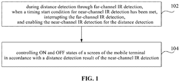
- the present disclosure provides in this embodiment a screen ON-and-OFF state control method which, as shown in FIG. 1 , includes the following steps.
- Step 102 during a distance detection through a far-channel IR detection, when a timing start condition for near-channel IR detection has been met, interrupting the far-channel IR detection, and enabling the near-channel IR detection for the distance detection.
- a transmission power of an IR light beam corresponding to the far-channel IR detection may be greater than a transmission power of an IR light beam corresponding to the near-channel IR detection.
- the far-channel IR detection may be enabled by a dual IR distance detection system for the distance detection.
- the far-channel IR detection may be interrupted periodically in accordance with the predetermined timing start condition of the near-channel IR detection, and the near-channel IR detection may be enabled for the distance detection, so as to determine whether there is an obstacle too close to a screen.
- one emitter may be used by both the far-channel IR detection and the near-channel IR detection.
- an IR light beam at a first transmission power may be emitted by the emitter, so as to perform the distance detection through the far-channel IR detection.
- the transmission power of the IR light beam emitted by the emitter may be reduced from the first transmission power down to a second transmission power, so as to perform the distance detection through the near-channel IR detection.
- the first transmission power may be greater than the second transmission power.
- the first transmission power and the second transmission power may be determined according to the practical need, and thus will not be particularly defined herein.
- the step of, during the distance detection through the far-channel IR detection, when the timing start condition for the near-channel IR detection has been met, interrupting the far-channel IR detection and enabling the near-channel IR detection for the distance detection may include: receiving a timing signal from a timer, the timing signal being transmitted by the timer at a predetermined frequency; upon the receipt of the timing signal, determining an ON/OFF state of the screen of the mobile terminal; and when the screen of the mobile terminal is in the ON state, interrupting the far-channel IR detection, and enabling the near-channel IR detection for the distance detection.
- the timer may be preset in the dual IR distance detection system and configured to transmit the timing signal to the dual IR distance detection system at the predetermined frequency.
- the predetermined frequency may be set according to the practical need, and thus will not be particularly defined herein.
- the dual IR distance detection system may determine the ON/OFF state of the screen of the mobile terminal.
- the dual IR distance detection system may be still maintained to perform the distance detection through the far-channel IR detection and wait for a next timing signal from the timer.
- the far-channel IR detection may be interrupted by the dual IR distance detection system, and the near-channel IR detection may be enabled for the distance detection.
- the near-channel IR detection Through the predetermined timing start condition of the near-channel IR detection, it is able to switch the far-channel IR detection to the near-channel IR detection independent of a distance detection result of the far-channel IR detection, thereby to perform the distance detection independently through the far-channel IR detection and the near-channel IR detection.
- Step 104 controlling the ON and OFF states of the screen of the mobile terminal in accordance with a distance detection result of the near-channel IR detection.
- the controlling the ON and OFF states of the screen of the mobile terminal in accordance with the distance detection result of the near-channel IR detection may include: determining a first proximity distance acquired through the near-channel IR detection; when the first proximity distance is smaller than or equal to a predetermined screen-off threshold corresponding to the near-channel IR detection, controlling the screen of the mobile terminal to be in the OFF state; and when the first proximity distance is greater than the predetermined screen-off threshold corresponding to the near-channel IR detection, interrupting the near-channel IR detection and enabling the far-channel IR detection for the distance detection.
- the predetermined screen-off threshold corresponding to the near-channel IR detection may be preset.
- the ON and OFF states of the screen of the mobile terminal may be controlled in accordance with the predetermined screen-off threshold corresponding to the near-channel IR detection and the first proximity distance acquired through the near-channel IR detection.
- the screen of the mobile terminal may be controlled to be in the OFF state, so as to prevent the occurrence of the misoperation made by the obstacle on the screen of the mobile terminal.
- the dual IR distance detection system may interrupt the near-channel IR detection, enable the far-channel IR detection for the distance detection, and wait for a next timing signal from the timer.
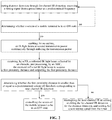
- FIG. 2 is a flow chart of the near-channel IR detection, which includes the following steps.
- Step 202 during the distance detection through the far-channel IR detection, receiving the timing signal from the preset timer at the predetermined frequency.
- the emitter may emit the IR light beam at the first transmission power continuously.
- Step 204 determining whether the screen of the mobile terminal is in the ON state, if yes, proceeding to Step 206, and otherwise, returning to Step 202 and waiting for a next timing signal from the timer.
- Step 206 emitting, by the emitter, the IR light beam at the second transmission power continuously through reducing the transmission power.
- the first transmission power may be greater than the second transmission power.
- Step 208 receiving, by a photodiode (PD), a reflected IR light beam reflected by the obstacle, and processing the received reflected IR light beam to acquire the first proximity distance and outputting the first proximity distance by an analog-to-digital converter (ADC), i.e., the first proximity distance acquired through the near-channel IR detection.
- PD photodiode
- ADC analog-to-digital converter
- Step 210 determining whether the first proximity distance is smaller than or equal to the predetermined screen-off threshold corresponding to the near-channel IR detection, if yes, proceeding to Step 212, and otherwise, proceeding to Step 214.
- Step 212 when the obstacle is close to the screen of the mobile terminal, controlling the screen of the mobile terminal to be in the OFF state, so as to prevent the occurrence of the misoperation made by the obstacle on the screen of the mobile terminal.
- Step 214 when there is no obstacle close to the screen of the mobile terminal, interrupting the near-channel IR detection by the dual IR distance detection system, enabling the far-channel IR detection for the distance detection, and waiting for a next timing signal from the timer.
- the far-channel IR detection may be switched to the near-channel IR detection periodically in accordance with the timing start condition of the near-channel IR detection.
- the far-channel IR detection may perform the distance detection independently through the far-channel IR detection and the near-channel IR detection. Even when failure occurs for the far-channel IR detection, it is still able to perform the distance detection through the near-channel IR detection, thereby to improve the distance detection accuracy.
- the method may further include: determining a second proximity distance acquired through the far-channel IR detection; and when the second proximity distance is smaller than or equal to a predetermined screen-off threshold corresponding to the far-channel IR detection, controlling the screen of the mobile terminal to be in the OFF state.
- the predetermined screen-off threshold corresponding to the far-channel IR detection may be preset.
- the ON and OFF states of the screen of the mobile terminal may be controlled in accordance with the predetermined screen-off threshold corresponding to the far-channel IR detection and the second proximity distance acquired through the far-channel IR detection.
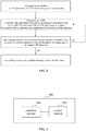
- FIG. 3 is a flow chart of the far-channel IR detection, which includes the following steps.
- Step 302 emitting the IR light beam at the first transmission power continuously by the emitter.
- Step 304 receiving, by the PD, a reflected IR light beam reflected by the obstacle, and processing the received reflected IR light beam to acquire the second proximity distance and outputting the second proximity distance by the ADC, i.e., the second proximity distance acquired through the far-channel IR detection.
- Step 306 determining whether the second proximity distance is smaller than or equal to the predetermined screen-off threshold corresponding to the far-channel IR detection, if yes, proceeding to Step 308, and otherwise, returning to Step 304 and continuously monitoring the second proximity distance acquired through the far-channel IR detection.
- Step 308 when the obstacle is close to the screen of the mobile terminal, controlling the screen of the mobile terminal to be in the OFF state, so as to prevent the occurrence of the misoperation made by the obstacle on the screen of the mobile terminal.
- a predetermined screen-on threshold corresponding to the far-channel IR detection may be preset.
- the ON and OFF states of the screen of the mobile terminal may be controlled in accordance with the predetermined screen-on threshold corresponding to the far-channel IR detection and the second proximity distance acquired through the far-channel IR detection.
- the screen of the mobile terminal may be controlled to be in the ON state, so as to prevent a normal operation made by a user on the mobile terminal from being adversely affected.
- the far-channel IR detection may be interrupted, and the near-channel IR detection may be enabled for the distance detection.
- the transmission power of the IR light beam corresponding to the far-channel IR detection may be greater than the transmission power of the IR light beam corresponding to the near-channel IR detection. Then, the ON and OFF states of the screen of the mobile terminal may be controlled in accordance with the distance detection result of the near-channel IR detection.
- the present disclosure further provides in this embodiment a mobile terminal 400 which, as shown in FIG. 4 , includes: a switching module 401 configured to, during distance detection through the far-channel IR detection, when a timing start condition for the near-channel IR detection has been met, interrupt the far-channel IR detection, and enable the near-channel IR detection for the distance detection; and a control module 402 configured to control ON and OFF states of a screen of the mobile terminal in accordance with a distance detection result of the near-channel IR detection.
- the transmission power of an IR light beam corresponding to the far-channel IR detection may be greater than transmission power of an IR light beam corresponding to the near-channel IR detection.
- the switching module 402 may further include: a reception unit configured to receive a timing signal from a timer, the timing signal being transmitted by the timer at a predetermined frequency; a determination unit configured to, upon the receipt of the timing signal, determine an ON/OFF state of the screen of the mobile terminal; and a switching unit configured to, when the screen of the mobile terminal is in the ON state, interrupt the far-channel IR detection, and enable the near-channel IR detection for the distance detection.
- control module 403 may further include: a determination unit configured to determine a first proximity distance acquired through the near-channel IR detection; and a control unit configured to, when the first proximity distance is smaller than or equal to a predetermined screen-off threshold corresponding to the near-channel IR detection, control the screen of the mobile terminal to be in the OFF state.
- the switching module 402 is further configured to, when the first proximity distance is greater than the predetermined screen-off threshold corresponding to the near-channel IR detection, interrupt the near-channel IR detection and enable the far-channel IR detection for the distance detection.
- the mobile terminal 400 may further include: a determination module 403 configured to determine a second proximity distance acquired through the far-channel IR detection, a control module 402 which is further configured to, when the second proximity distance is smaller than or equal to a predetermined screen-off threshold corresponding to the far-channel IR detection, control the screen of the mobile terminal to be in the OFF state.
- the mobile terminal in this embodiment is capable of implementing the procedures for the mobile terminal in the first embodiment, and thus will not be particularly defined herein.
- FIG. 5 shows a hardware structure of a mobile terminal according to some embodiments of the present disclosure.
- the mobile terminal 500 may include, but not limited to, a Radio Frequency (RF) unit 501, a network module 502, an audio output unit 503, an input unit 504, a sensor 505, a display unit 506, a user input unit 507, an interface unit 508, a memory 509, a processor 510, and a power source 511.
- RF Radio Frequency
- the mobile terminal may include more or fewer members, or some members may be combined, or the mobile terminal may include some other members not shown in FIG. 5 .
- the mobile terminal may include, but not limited to, mobile phone, flat-panel computer, laptop computer, Personal Digital Assistant (PDA), vehicle-mounted terminal, wearable device or pedometer.
- PDA Personal Digital Assistant
- the processor 501 is configured to: during distance detection through the far-channel IR detection, when a timing start condition for the near-channel IR detection has been met, interrupt the far-channel IR detection, and enable the near-channel IR detection for the distance detection; and control ON and OFF states of a screen of the mobile terminal in accordance with a distance detection result of the near-channel IR detection.
- the transmission power of an IR light beam corresponding to the far-channel IR detection may be greater than transmission power of an IR light beam corresponding to the near-channel IR detection.
- the far-channel IR detection may be interrupted, and the near-channel IR detection may be enabled for the distance detection.
- the transmission power of the IR light beam corresponding to the far-channel IR detection may be greater than the transmission power of the IR light beam corresponding to the near-channel IR detection. Then, the ON and OFF states of the screen of the mobile terminal may be controlled in accordance with the distance detection result of the near-channel IR detection.
- the RF unit 501 is configured to transmit and receive signals during the information transmission or phone call.
- the RF unit 501 may, upon the receipt of downlink data from a base station, transmit the downlink data to the processor 510 for subsequent treatment.
- the RF unit 501 may transmit uplink data to the base station.
- the RF unit 501 may include, but not limited to, an antenna, at least one amplifier, a transceiver, a coupler, a low-noise amplifier and a duplexer.
- the RF unit 501 may communicate with a network and the other devices via a wireless communication system.
- the network module 502 is configured to enable the mobile terminal to access the broadband Internet in a wireless manner, e.g., help a user to receive and send an e-mail, browse a web page or access a streaming media.
- the audio output unit 503 is configured to convert audio data received by the RF unit 501 or the network module 502, or audio data stored in the memory 509, into an audio signal and output the audio signal as a sound.
- the audio output unit 503 is further configured to provide an audio output related to a specific function executed by the mobile terminal 500 (e.g., a sound occurring when a calling signal or a message has been received).
- the audio output unit 503 may include a loudspeaker, a buzzer and a receiver.
- the input unit 504 is configured to receive an audio or video signal. It may include a Graphics Processing Unit (GPU) 5041 and a microphone 5042.
- the GPU 5041 is configured to process image data of a static image or video acquired by an image collection unit (e.g., a camera) in a video capturing mode or an image capturing mode, and a processed image frame may be displayed by the display unit 506.
- the image frame processed by the GPU 5041 may be stored in the memory 509 (or any other storage medium) or transmitted via the RF unit 501 or network module 502.
- the microphone 5042 is configured to receive a sound, and convert the sound into voice data. In a call mode, the processed audio data may be converted into data in a format capable of being transmitted by the RF unit 501 to a mobile communication base station.
- the mobile terminal 500 contains at least one sensor 505, which may include a light sensor, a movement sensor and the other sensors.
- the light sensor may include an ambient light sensor or a proximity sensor.
- the ambient light sensor is configured to adjust a brightness value of a display panel 5061 in accordance with ambient light.
- the proximity sensor is configured to turn off the display panel 5061 and/or a backlight source when the mobile terminal 500 moves close to an ear.
- an accelerometer may detect acceleration in various directions (usually a three-axis accelerometer), and detect a level and a direction of a gravity force in a static state.
- the accelerometer it is able to identify a posture of the mobile terminal (e.g., perform a switching operation between portrait and landscape orientations, play relevant games, and calibrate a posture of a magnetometer), and perform vibration-related functions (e.g., count steps and strikes).
- the sensor 505 may further include a fingerprint sensor, a pressure sensor, an iris sensor, a molecule sensor, a gyroscope, a barometer, a hygrometer, a thermometer or an infrared sensor, which will not be particularly defined herein.
- the display unit 506 is configured to display information inputted by the user or provided to the user.
- the display unit 506 may include the display panel 5061, e.g., a Liquid Crystal Display (LCD) panel, or an Organic Light-Emitting Diode (OLED) panel.
- LCD Liquid Crystal Display
- OLED Organic Light-Emitting Diode
- the user input unit 507 is configured to receive digital or character information inputted by the user, and generate a key signal input related to user settings and function control of the mobile terminal.
- the user input unit 507 may include a touch panel 5071 and another input device 5072.
- the touch panel 5071 also called as touch screen, is configured to collect a touch operation made by the user on or in proximity to the touch panel (e.g., an operation made by the user through any appropriate object or attachment (e.g., finger or stylus) on or in the proximity to the touch panel 5071).
- the touch panel 5071 may include a touch detection unit and a touch controller.
- the touch detection unit is configured to detect a touch position and a signal generated due to the touch operation, and to transmit the signal to the touch controller.
- the touch controller is configured to receive touch information from the touch detection unit, convert it into coordinates of a touch point, transmit the coordinates to the processor 510, and receive and execute a command from the processor 510.
- the touch panel 5071 may be of a resistive type, a capacitive type, an infrared type or a surface acoustic wave (SAW) type.
- the other input device 5072 may include, but not limited to, a physical keyboard, a functional button (e.g., a volume control button or an on/off button), a trackball, a mouse, and a joystick, which will not be particularly defined herein.
- the touch panel 5071 may cover the display panel 5061.
- the touch panel 5071 may transmit the touch information to the processor 510, so as to determine a type of a touch event.
- the processor 510 may control the display panel 5061 to provide a corresponding visual output in accordance with the type of the touch event.
- the touch panel 5071 and the display panel 5061 are configured as two separate members in FIG. 5 , in some embodiments of the present disclosure, they may be integrated so as to achieve the input and output functions of the electronic device, which will not be particularly defined herein.
- the interface unit 508 is configured to provide an interface between an external device and the mobile terminal 500.
- the external device may include a wired or wireless headset port, an external power source port (or a charging port), a wired or wireless data port, a memory card port, a port for a device having an identification module, an audio input/output (I/O) port, a video I/O port, and an earphone port.
- the interface unit 508 is configured to receive an input from the external device (e.g., data information and electricity) and transmit the input to one or more elements of the mobile terminal 500, or transmit data between the mobile terminal 500 and the external device.
- the memory 509 is configured to store therein a software application and various data. It may mainly include an application storage area and a data storage area. An operating system and at least one application for the functions (e.g., an audio/image playing function) may be stored in the application storage area. Data created in accordance with the operation of the mobile phone (e.g., audio data and textbook) may be stored in the data storage area.
- the memory 509 may include a high-speed random access memory (RAM), or a non-volatile memory (e.g., at least one magnetic disk or flash memory), or any other volatile solid state memory.
- the processor 510 may be connected to the other members of the electronic device via various interfaces and circuits, and configured to run or execute the software program and/or module stored in the memory 509, and call the data stored in the memory 509, so as to execute the functions of the electronic device and process the data, thereby to monitor the entire electronic device.
- the processor 510 may include one or more processing units.
- an application processor and a modem may be integrated into the processor 510.
- the application processor is mainly configured to process the operating system, a user interface and the application.
- the modem is mainly configured to process wireless communication. It should be appreciated that, the modem may also not be integrated into the processor 510.
- the power source 511 (e.g., a battery) is configured to supply power to the members of the mobile terminal 500.
- the power source 511 is logically connected to the processor 510 via a power source management system, so as to achieve such functions as charging, discharging and power consumption management through the power source management system.
- the mobile terminal 500 may include some functional modules not shown in FIG. 5 , which will not be particularly defined herein.
- the present disclosure further provides in some embodiments a mobile terminal, which includes a processor 510, a memory 509, and a screen ON-and-OFF state control program stored in the memory 509 and executed by the processor 510.
- the processor 510 is configured to execute the screen ON-and-OFF state control program so as to implement the above-mentioned screen ON-and-OFF state control method with a same technical effect, which will not be particularly defined herein.
- the present disclosure further provides in some embodiments a computer-readable storage medium storing therein a screen ON-and-OFF state control program.
- the screen ON-and-OFF state control program is executed by a processor so as to implement the above-mentioned screen ON-and-OFF state control method with a same technical effect, which will not be particularly defined herein.
- the computer-readable storage medium may be a ROM, an RAM, a magnetic disk or an optical disk.
- the present disclosure may be implemented by software as well as a necessary common hardware platform, or by hardware, and the former may be better in most cases.
- the technical solutions of the present disclosure partial or full, or parts of the technical solutions of the present disclosure contributing to the related art, may appear in the form of software products, which may be stored in a storage medium (e.g., ROM/RAM, magnetic disk or optical disk) and include several instructions so as to enable a terminal device (mobile phone, computer, server, air conditioner or network device) to execute the method in the embodiments of the present disclosure.
- a storage medium e.g., ROM/RAM, magnetic disk or optical disk
Landscapes
- Engineering & Computer Science (AREA)
- Signal Processing (AREA)
- Multimedia (AREA)
- Computer Networks & Wireless Communication (AREA)
- Health & Medical Sciences (AREA)
- Toxicology (AREA)
- Human Computer Interaction (AREA)
- Environmental & Geological Engineering (AREA)
- Theoretical Computer Science (AREA)
- Physics & Mathematics (AREA)
- General Engineering & Computer Science (AREA)
- General Physics & Mathematics (AREA)
- Telephone Function (AREA)
- Mobile Radio Communication Systems (AREA)
- Photometry And Measurement Of Optical Pulse Characteristics (AREA)
Abstract
Description
- The present application claims a priority of the Chinese patent application No.
201810090932.8 filed on January 30th, 2018 - The present disclosure relates to the field of a terminal, in particular to a screen ON-and-OFF state control method, and a mobile terminal.
- Current, distance detection is performed by a mobile terminal through an infrared (IR) sensor, so as to determine whether there is an obstacle too close to a screen of the mobile terminal, e.g., determine whether a user's face is too close to the screen during a call. When the user's face is too close to the screen, the screen is controlled to be in an OFF state, so as to prevent the occurrence of a misoperation for the reason that the screen is touched by the user's face unnecessarily.
- In actual use, usually a dual IR distance detection system is used by the mobile terminal to perform the distance detection. In the dual IR distance detection system, one emitter is used for both far-channel IR detection and near-channel IR detection. During the call, the distance detection is performed by the mobile terminal using the dual IR distance detection system. To be specific, at first, the far-channel IR detection is enabled, and an IR light beam at a first transmission power is emitted by the emitter for the distance detection. Next, when a proximity distance acquired through the far-channel IR detection reaches a switching threshold, the far-channel IR detection is switched to the near-channel IR detection, and, an IR light beam at a second transmission power smaller than the first transmission power, is emitted by the emitter for the distance detection. When the obstacle detected by the near-channel IR detection is too close to the screen, the screen of the mobile terminal is controlled to be in the OFF state.
- However, in the conventional dual-IR distance detection system, it is necessary to trigger the switching to the near-channel IR detection in accordance with a distance detection result of the far-channel IR detection. When the far-channel IR detection is abnormal, it is impossible to switch the far-channel IR detection to the near-channel IR detection. Under this circumstance, it is impossible to control the screen to be in the OFF state when the obstacle is too close to the screen. The distance detection accuracy of the dual-IR distance detection system is relatively low and it is impossible to control an ON state and the OFF state of the screen accurately, so the user experience may be affected adversely.
- An object of the present disclosure is to provide a screen ON-and-OFF state control method, so as to solve the problem in the related art that it is impossible to accurately control ON and OFF states of a screen of a mobile terminal due to relatively low distance detection accuracy of an IR distance detection system.
- In one aspect, the present disclosure provides in some embodiments a screen ON-and-OFF state control method, including: during the distance detection through the far-channel IR detection, when a timing start condition for the near-channel IR detection has been met, interrupting the far-channel IR detection, and enabling the near-channel IR detection for the distance detection; and controlling ON and OFF states of a screen of the mobile terminal in accordance with a distance detection result of the near-channel IR detection. Herein, a transmission power of an IR light beam corresponding to the far-channel IR detection is greater than a transmission power of an IR light beam corresponding to the near-channel IR detection.
- In another aspect, the present disclosure provides in some embodiments a mobile terminal, including: a processing module configured to, during the distance detection through the far-channel IR detection, when a timing start condition for the near-channel IR detection has been met, interrupt the far-channel IR detection, and enable the near-channel IR detection for the distance detection; and a control module configured to control ON and OFF states of a screen of the mobile terminal in accordance with a distance detection result of the near-channel IR detection. Herein, the transmission power of an IR light beam corresponding to the far-channel IR detection is greater than the transmission power of an IR light beam corresponding to the near-channel IR detection.
- In yet another aspect, the present disclosure provides in some embodiments a mobile terminal, including a processor, a memory, and a screen ON-and-OFF state control program stored in the memory and executed by the processor. The processor is configured to execute the screen ON-and-OFF state control program so as to implement the above-mentioned screen ON-and-OFF state control method.
- In still yet another aspect, the present disclosure provides in some embodiments a computer-readable storage medium storing therein a screen ON-and-OFF state control program. The screen ON-and-OFF state control program is executed by a processor so as to implement the above-mentioned screen ON-and-OFF state control method.
- According to the embodiments of the present disclosure, during the distance detection through the far-channel IR detection, when the timing start condition for the near-channel IR detection has been met, the far-channel IR detection may be interrupted, and the near-channel IR detection may be enabled for the distance detection. The transmission power of the IR light beam corresponding to the far-channel IR detection may be greater than the transmission power of the IR light beam corresponding to the near-channel IR detection. Then, the ON and OFF states of the screen of the mobile terminal may be controlled in accordance with the distance detection result of the near-channel IR detection. As a result, it is able to periodically switch the far-channel IR detection to the near-channel IR detection, improve the distance detection accuracy of the dual IR detection and accurately control the ON and OFF states of the screen of the mobile terminal, thereby to improve the user experience.
- The following drawings are provided to facilitate the understanding of the present disclosure, and constitute a portion of the description. These drawings and the following embodiments are for illustrative purposes only, but shall not be comprehended as limiting the present disclosure. In these drawings,
-
FIG. 1 is a flow chart of a screen ON-and-OFF state control method according to some embodiments of the present disclosure; -
FIG. 2 is a flow chart of the near-channel IR detection according to some embodiments of the present disclosure; -
FIG. 3 is a flow chart of the far-channel IR detection according to some embodiments of the present disclosure; -
FIG. 4 is a schematic view showing a mobile terminal according to some embodiments of the present disclosure; and -
FIG. 5 is a schematic view showing a hardware structure of the mobile terminal according to some embodiments of the present disclosure. - In order to make the objects, the technical solutions and the advantages of the present disclosure more apparent, the present disclosure will be described hereinafter in a clear and complete manner in conjunction with the drawings and embodiments. Obviously, the following embodiments merely relate to a part of, rather than all of, the embodiments of the present disclosure, and based on these embodiments, a person skilled in the art may, without any creative effort, obtain the other embodiments, which also fall within the scope of the present disclosure.
- The present disclosure will be described hereinafter in conjunction with the drawings and embodiments.
- The present disclosure provides in this embodiment a screen ON-and-OFF state control method which, as shown in
FIG. 1 , includes the following steps. - Step 102: during a distance detection through a far-channel IR detection, when a timing start condition for near-channel IR detection has been met, interrupting the far-channel IR detection, and enabling the near-channel IR detection for the distance detection. A transmission power of an IR light beam corresponding to the far-channel IR detection may be greater than a transmission power of an IR light beam corresponding to the near-channel IR detection.
- When a user is using a mobile terminal, the far-channel IR detection may be enabled by a dual IR distance detection system for the distance detection. During the distance detection through the far-channel IR detection, the far-channel IR detection may be interrupted periodically in accordance with the predetermined timing start condition of the near-channel IR detection, and the near-channel IR detection may be enabled for the distance detection, so as to determine whether there is an obstacle too close to a screen.
- In the dual IR distance detection system, one emitter may be used by both the far-channel IR detection and the near-channel IR detection. During the far-channel IR detection, an IR light beam at a first transmission power may be emitted by the emitter, so as to perform the distance detection through the far-channel IR detection. When the timing start condition of the near-channel IR detection has been met, the transmission power of the IR light beam emitted by the emitter may be reduced from the first transmission power down to a second transmission power, so as to perform the distance detection through the near-channel IR detection. Herein, the first transmission power may be greater than the second transmission power.
- It should be appreciated that, the first transmission power and the second transmission power may be determined according to the practical need, and thus will not be particularly defined herein.
- In the embodiments of the present disclosure, the step of, during the distance detection through the far-channel IR detection, when the timing start condition for the near-channel IR detection has been met, interrupting the far-channel IR detection and enabling the near-channel IR detection for the distance detection may include: receiving a timing signal from a timer, the timing signal being transmitted by the timer at a predetermined frequency; upon the receipt of the timing signal, determining an ON/OFF state of the screen of the mobile terminal; and when the screen of the mobile terminal is in the ON state, interrupting the far-channel IR detection, and enabling the near-channel IR detection for the distance detection.
- The timer may be preset in the dual IR distance detection system and configured to transmit the timing signal to the dual IR distance detection system at the predetermined frequency.
- It should be appreciated that, the predetermined frequency may be set according to the practical need, and thus will not be particularly defined herein.
- Upon the receipt of the timing signal, the dual IR distance detection system may determine the ON/OFF state of the screen of the mobile terminal.
- When the screen of the mobile terminal is in the OFF state, it means that the obstacle close to the screen of the mobile terminal has been detected through the far-channel IR detection, and the screen of the mobile terminal has been controlled to be in the OFF state. At this time, the dual IR distance detection system may be still maintained to perform the distance detection through the far-channel IR detection and wait for a next timing signal from the timer.
- When the screen of the mobile terminal is in the ON state, it means that no obstacle close to the screen of the mobile terminal has been detected through the far-channel IR detection, and at this time, the far-channel IR detection may be interrupted by the dual IR distance detection system, and the near-channel IR detection may be enabled for the distance detection.
- Through reducing the transmission power of the emitter, it is able to switch the far-channel IR detection to the near-channel IR detection for the dual IR distance detection system.
- Through the predetermined timing start condition of the near-channel IR detection, it is able to switch the far-channel IR detection to the near-channel IR detection independent of a distance detection result of the far-channel IR detection, thereby to perform the distance detection independently through the far-channel IR detection and the near-channel IR detection.
- Step 104: controlling the ON and OFF states of the screen of the mobile terminal in accordance with a distance detection result of the near-channel IR detection.
- To be specific, the controlling the ON and OFF states of the screen of the mobile terminal in accordance with the distance detection result of the near-channel IR detection may include: determining a first proximity distance acquired through the near-channel IR detection; when the first proximity distance is smaller than or equal to a predetermined screen-off threshold corresponding to the near-channel IR detection, controlling the screen of the mobile terminal to be in the OFF state; and when the first proximity distance is greater than the predetermined screen-off threshold corresponding to the near-channel IR detection, interrupting the near-channel IR detection and enabling the far-channel IR detection for the distance detection.
- With respect to the near-channel IR detection, the predetermined screen-off threshold corresponding to the near-channel IR detection may be preset. During the distance detection through the near-channel IR detection, the ON and OFF states of the screen of the mobile terminal may be controlled in accordance with the predetermined screen-off threshold corresponding to the near-channel IR detection and the first proximity distance acquired through the near-channel IR detection.
- When the first proximity distance is smaller than or equal to the predetermined screen-off threshold corresponding to the near-channel IR detection, it means that there is an obstacle close to the screen of the mobile terminal, and at this time, the screen of the mobile terminal may be controlled to be in the OFF state, so as to prevent the occurrence of the misoperation made by the obstacle on the screen of the mobile terminal.
- When the first proximity distance is greater than the predetermined screen-off threshold corresponding to the near-channel IR detection, it means that there is no obstacle close to the screen of the mobile terminal. At this time, the dual IR distance detection system may interrupt the near-channel IR detection, enable the far-channel IR detection for the distance detection, and wait for a next timing signal from the timer.
-
FIG. 2 is a flow chart of the near-channel IR detection, which includes the following steps. - Step 202: during the distance detection through the far-channel IR detection, receiving the timing signal from the preset timer at the predetermined frequency. During the distance detection through the far-channel IR detection, the emitter may emit the IR light beam at the first transmission power continuously.
- Step 204: determining whether the screen of the mobile terminal is in the ON state, if yes, proceeding to Step 206, and otherwise, returning to Step 202 and waiting for a next timing signal from the timer.
- Step 206: emitting, by the emitter, the IR light beam at the second transmission power continuously through reducing the transmission power. Herein, the first transmission power may be greater than the second transmission power.
- Step 208: receiving, by a photodiode (PD), a reflected IR light beam reflected by the obstacle, and processing the received reflected IR light beam to acquire the first proximity distance and outputting the first proximity distance by an analog-to-digital converter (ADC), i.e., the first proximity distance acquired through the near-channel IR detection.
- Step 210: determining whether the first proximity distance is smaller than or equal to the predetermined screen-off threshold corresponding to the near-channel IR detection, if yes, proceeding to Step 212, and otherwise, proceeding to Step 214.
- Step 212: when the obstacle is close to the screen of the mobile terminal, controlling the screen of the mobile terminal to be in the OFF state, so as to prevent the occurrence of the misoperation made by the obstacle on the screen of the mobile terminal.
- Step 214: when there is no obstacle close to the screen of the mobile terminal, interrupting the near-channel IR detection by the dual IR distance detection system, enabling the far-channel IR detection for the distance detection, and waiting for a next timing signal from the timer.
- During the continuous distance detection through the far-channel IR detection, the far-channel IR detection may be switched to the near-channel IR detection periodically in accordance with the timing start condition of the near-channel IR detection. Hence, in the case that one emitter is used by both the far-channel IR detection and the near-channel IR detection, it is able to perform the distance detection independently through the far-channel IR detection and the near-channel IR detection. Even when failure occurs for the far-channel IR detection, it is still able to perform the distance detection through the near-channel IR detection, thereby to improve the distance detection accuracy.
- In the embodiments of the present disclosure, the method may further include: determining a second proximity distance acquired through the far-channel IR detection; and when the second proximity distance is smaller than or equal to a predetermined screen-off threshold corresponding to the far-channel IR detection, controlling the screen of the mobile terminal to be in the OFF state.
- With respect to the far-channel IR detection, the predetermined screen-off threshold corresponding to the far-channel IR detection may be preset. During the distance detection through the far-channel IR detection, the ON and OFF states of the screen of the mobile terminal may be controlled in accordance with the predetermined screen-off threshold corresponding to the far-channel IR detection and the second proximity distance acquired through the far-channel IR detection.
-
FIG. 3 is a flow chart of the far-channel IR detection, which includes the following steps. - Step 302: emitting the IR light beam at the first transmission power continuously by the emitter.
- Step 304: receiving, by the PD, a reflected IR light beam reflected by the obstacle, and processing the received reflected IR light beam to acquire the second proximity distance and outputting the second proximity distance by the ADC, i.e., the second proximity distance acquired through the far-channel IR detection.
- Step 306: determining whether the second proximity distance is smaller than or equal to the predetermined screen-off threshold corresponding to the far-channel IR detection, if yes, proceeding to Step 308, and otherwise, returning to Step 304 and continuously monitoring the second proximity distance acquired through the far-channel IR detection.
- Step 308: when the obstacle is close to the screen of the mobile terminal, controlling the screen of the mobile terminal to be in the OFF state, so as to prevent the occurrence of the misoperation made by the obstacle on the screen of the mobile terminal.
- With respect to the far-channel IR detection, a predetermined screen-on threshold corresponding to the far-channel IR detection may be preset. During the distance detection through the far-channel IR detection, when the screen of the mobile terminal is in the OFF state, the ON and OFF states of the screen of the mobile terminal may be controlled in accordance with the predetermined screen-on threshold corresponding to the far-channel IR detection and the second proximity distance acquired through the far-channel IR detection.
- When the second proximity distance is greater than or equal to the predetermined screen-on threshold corresponding to the far-channel IR detection, the screen of the mobile terminal may be controlled to be in the ON state, so as to prevent a normal operation made by a user on the mobile terminal from being adversely affected.
- According to the embodiments of the present disclosure, during the distance detection through the far-channel IR detection, when the timing start condition for the near-channel IR detection has been met, the far-channel IR detection may be interrupted, and the near-channel IR detection may be enabled for the distance detection. The transmission power of the IR light beam corresponding to the far-channel IR detection may be greater than the transmission power of the IR light beam corresponding to the near-channel IR detection. Then, the ON and OFF states of the screen of the mobile terminal may be controlled in accordance with the distance detection result of the near-channel IR detection. As a result, it is able to periodically switch the far-channel IR detection to the near-channel IR detection, improve the distance detection accuracy of the dual IR detection and accurately control the ON and OFF states of the screen of the mobile terminal, thereby to improve the user experience.
- The present disclosure further provides in this embodiment a
mobile terminal 400 which, as shown inFIG. 4 , includes: a switchingmodule 401 configured to, during distance detection through the far-channel IR detection, when a timing start condition for the near-channel IR detection has been met, interrupt the far-channel IR detection, and enable the near-channel IR detection for the distance detection; and acontrol module 402 configured to control ON and OFF states of a screen of the mobile terminal in accordance with a distance detection result of the near-channel IR detection. The transmission power of an IR light beam corresponding to the far-channel IR detection may be greater than transmission power of an IR light beam corresponding to the near-channel IR detection. - In a possible embodiment of the present disclosure, the
switching module 402 may further include: a reception unit configured to receive a timing signal from a timer, the timing signal being transmitted by the timer at a predetermined frequency; a determination unit configured to, upon the receipt of the timing signal, determine an ON/OFF state of the screen of the mobile terminal; and a switching unit configured to, when the screen of the mobile terminal is in the ON state, interrupt the far-channel IR detection, and enable the near-channel IR detection for the distance detection. - In a possible embodiment of the present disclosure, the control module 403 may further include: a determination unit configured to determine a first proximity distance acquired through the near-channel IR detection; and a control unit configured to, when the first proximity distance is smaller than or equal to a predetermined screen-off threshold corresponding to the near-channel IR detection, control the screen of the mobile terminal to be in the OFF state.
- In a possible embodiment of the present disclosure, the
switching module 402 is further configured to, when the first proximity distance is greater than the predetermined screen-off threshold corresponding to the near-channel IR detection, interrupt the near-channel IR detection and enable the far-channel IR detection for the distance detection. - In a possible embodiment of the present disclosure, the
mobile terminal 400 may further include: a determination module 403 configured to determine a second proximity distance acquired through the far-channel IR detection, acontrol module 402 which is further configured to, when the second proximity distance is smaller than or equal to a predetermined screen-off threshold corresponding to the far-channel IR detection, control the screen of the mobile terminal to be in the OFF state. - The mobile terminal in this embodiment is capable of implementing the procedures for the mobile terminal in the first embodiment, and thus will not be particularly defined herein.
-
FIG. 5 shows a hardware structure of a mobile terminal according to some embodiments of the present disclosure. Themobile terminal 500 may include, but not limited to, a Radio Frequency (RF)unit 501, a network module 502, anaudio output unit 503, an input unit 504, asensor 505, adisplay unit 506, auser input unit 507, aninterface unit 508, amemory 509, aprocessor 510, and apower source 511. It should be appreciated that, the structure inFIG. 5 shall not be comprehended as limiting the mobile terminal. The mobile terminal may include more or fewer members, or some members may be combined, or the mobile terminal may include some other members not shown inFIG. 5 . In the embodiments of the present disclosure, the mobile terminal may include, but not limited to, mobile phone, flat-panel computer, laptop computer, Personal Digital Assistant (PDA), vehicle-mounted terminal, wearable device or pedometer. - The
processor 501 is configured to: during distance detection through the far-channel IR detection, when a timing start condition for the near-channel IR detection has been met, interrupt the far-channel IR detection, and enable the near-channel IR detection for the distance detection; and control ON and OFF states of a screen of the mobile terminal in accordance with a distance detection result of the near-channel IR detection. The transmission power of an IR light beam corresponding to the far-channel IR detection may be greater than transmission power of an IR light beam corresponding to the near-channel IR detection. - During the distance detection through the far-channel IR detection, when the timing start condition for the near-channel IR detection has been met, the far-channel IR detection may be interrupted, and the near-channel IR detection may be enabled for the distance detection. The transmission power of the IR light beam corresponding to the far-channel IR detection may be greater than the transmission power of the IR light beam corresponding to the near-channel IR detection. Then, the ON and OFF states of the screen of the mobile terminal may be controlled in accordance with the distance detection result of the near-channel IR detection. As a result, it is able to periodically switch the far-channel IR detection to the near-channel IR detection, improve the distance detection accuracy of the dual IR detection and accurately control the ON and OFF states of the screen of the mobile terminal, thereby to improve the user experience.
- It should be appreciated that, in the embodiments of the present disclosure, the
RF unit 501 is configured to transmit and receive signals during the information transmission or phone call. To be specific, theRF unit 501 may, upon the receipt of downlink data from a base station, transmit the downlink data to theprocessor 510 for subsequent treatment. In addition, theRF unit 501 may transmit uplink data to the base station. Usually, theRF unit 501 may include, but not limited to, an antenna, at least one amplifier, a transceiver, a coupler, a low-noise amplifier and a duplexer. In addition, theRF unit 501 may communicate with a network and the other devices via a wireless communication system. - The network module 502 is configured to enable the mobile terminal to access the broadband Internet in a wireless manner, e.g., help a user to receive and send an e-mail, browse a web page or access a streaming media.
- The
audio output unit 503 is configured to convert audio data received by theRF unit 501 or the network module 502, or audio data stored in thememory 509, into an audio signal and output the audio signal as a sound. In addition, theaudio output unit 503 is further configured to provide an audio output related to a specific function executed by the mobile terminal 500 (e.g., a sound occurring when a calling signal or a message has been received). Theaudio output unit 503 may include a loudspeaker, a buzzer and a receiver. - The input unit 504 is configured to receive an audio or video signal. It may include a Graphics Processing Unit (GPU) 5041 and a
microphone 5042. TheGPU 5041 is configured to process image data of a static image or video acquired by an image collection unit (e.g., a camera) in a video capturing mode or an image capturing mode, and a processed image frame may be displayed by thedisplay unit 506. The image frame processed by theGPU 5041 may be stored in the memory 509 (or any other storage medium) or transmitted via theRF unit 501 or network module 502. Themicrophone 5042 is configured to receive a sound, and convert the sound into voice data. In a call mode, the processed audio data may be converted into data in a format capable of being transmitted by theRF unit 501 to a mobile communication base station. - The
mobile terminal 500 contains at least onesensor 505, which may include a light sensor, a movement sensor and the other sensors. To be specific, the light sensor may include an ambient light sensor or a proximity sensor. The ambient light sensor is configured to adjust a brightness value of adisplay panel 5061 in accordance with ambient light. The proximity sensor is configured to turn off thedisplay panel 5061 and/or a backlight source when themobile terminal 500 moves close to an ear. As one of the movement sensors, an accelerometer may detect acceleration in various directions (usually a three-axis accelerometer), and detect a level and a direction of a gravity force in a static state. Through the accelerometer, it is able to identify a posture of the mobile terminal (e.g., perform a switching operation between portrait and landscape orientations, play relevant games, and calibrate a posture of a magnetometer), and perform vibration-related functions (e.g., count steps and strikes). Thesensor 505 may further include a fingerprint sensor, a pressure sensor, an iris sensor, a molecule sensor, a gyroscope, a barometer, a hygrometer, a thermometer or an infrared sensor, which will not be particularly defined herein. - The
display unit 506 is configured to display information inputted by the user or provided to the user. Thedisplay unit 506 may include thedisplay panel 5061, e.g., a Liquid Crystal Display (LCD) panel, or an Organic Light-Emitting Diode (OLED) panel. - The
user input unit 507 is configured to receive digital or character information inputted by the user, and generate a key signal input related to user settings and function control of the mobile terminal. To be specific, theuser input unit 507 may include atouch panel 5071 and anotherinput device 5072. Thetouch panel 5071, also called as touch screen, is configured to collect a touch operation made by the user on or in proximity to the touch panel (e.g., an operation made by the user through any appropriate object or attachment (e.g., finger or stylus) on or in the proximity to the touch panel 5071). Thetouch panel 5071 may include a touch detection unit and a touch controller. The touch detection unit is configured to detect a touch position and a signal generated due to the touch operation, and to transmit the signal to the touch controller. The touch controller is configured to receive touch information from the touch detection unit, convert it into coordinates of a touch point, transmit the coordinates to theprocessor 510, and receive and execute a command from theprocessor 510. In addition, thetouch panel 5071 may be of a resistive type, a capacitive type, an infrared type or a surface acoustic wave (SAW) type. Theother input device 5072 may include, but not limited to, a physical keyboard, a functional button (e.g., a volume control button or an on/off button), a trackball, a mouse, and a joystick, which will not be particularly defined herein. - Further, the
touch panel 5071 may cover thedisplay panel 5061. When the touch operation made on or in proximity to thetouch panel 5071 has been detected, thetouch panel 5071 may transmit the touch information to theprocessor 510, so as to determine a type of a touch event. Then, theprocessor 510 may control thedisplay panel 5061 to provide a corresponding visual output in accordance with the type of the touch event. Although thetouch panel 5071 and thedisplay panel 5061 are configured as two separate members inFIG. 5 , in some embodiments of the present disclosure, they may be integrated so as to achieve the input and output functions of the electronic device, which will not be particularly defined herein. - The
interface unit 508 is configured to provide an interface between an external device and themobile terminal 500. For example, the external device may include a wired or wireless headset port, an external power source port (or a charging port), a wired or wireless data port, a memory card port, a port for a device having an identification module, an audio input/output (I/O) port, a video I/O port, and an earphone port. Theinterface unit 508 is configured to receive an input from the external device (e.g., data information and electricity) and transmit the input to one or more elements of themobile terminal 500, or transmit data between themobile terminal 500 and the external device. - The
memory 509 is configured to store therein a software application and various data. It may mainly include an application storage area and a data storage area. An operating system and at least one application for the functions (e.g., an audio/image playing function) may be stored in the application storage area. Data created in accordance with the operation of the mobile phone (e.g., audio data and textbook) may be stored in the data storage area. In addition, thememory 509 may include a high-speed random access memory (RAM), or a non-volatile memory (e.g., at least one magnetic disk or flash memory), or any other volatile solid state memory. - As a control center of the electronic device, the
processor 510 may be connected to the other members of the electronic device via various interfaces and circuits, and configured to run or execute the software program and/or module stored in thememory 509, and call the data stored in thememory 509, so as to execute the functions of the electronic device and process the data, thereby to monitor the entire electronic device. Theprocessor 510 may include one or more processing units. In a possible embodiment of the present disclosure, an application processor and a modem may be integrated into theprocessor 510. The application processor is mainly configured to process the operating system, a user interface and the application. The modem is mainly configured to process wireless communication. It should be appreciated that, the modem may also not be integrated into theprocessor 510. - The power source 511 (e.g., a battery) is configured to supply power to the members of the
mobile terminal 500. In a possible embodiment of the present disclosure, thepower source 511 is logically connected to theprocessor 510 via a power source management system, so as to achieve such functions as charging, discharging and power consumption management through the power source management system. - In addition, the
mobile terminal 500 may include some functional modules not shown inFIG. 5 , which will not be particularly defined herein. - The present disclosure further provides in some embodiments a mobile terminal, which includes a
processor 510, amemory 509, and a screen ON-and-OFF state control program stored in thememory 509 and executed by theprocessor 510. Theprocessor 510 is configured to execute the screen ON-and-OFF state control program so as to implement the above-mentioned screen ON-and-OFF state control method with a same technical effect, which will not be particularly defined herein. - The present disclosure further provides in some embodiments a computer-readable storage medium storing therein a screen ON-and-OFF state control program. The screen ON-and-OFF state control program is executed by a processor so as to implement the above-mentioned screen ON-and-OFF state control method with a same technical effect, which will not be particularly defined herein. The computer-readable storage medium may be a ROM, an RAM, a magnetic disk or an optical disk.
- It should be appreciated that, such words as "include" or "including" or any other variations involved in the present disclosure intend to provide non-exclusive coverage, so that a procedure, method, article or device including a series of elements may also include any other elements not listed herein, or may include any inherent elements of the procedure, method, article or device. If without any further limitations, for the elements defined by such sentence as "including one ...", it is not excluded that the procedure, method, article or device including the elements may also include any other identical elements.
- Through the above-mentioned description, it may be apparent for a person skilled in the art that the present disclosure may be implemented by software as well as a necessary common hardware platform, or by hardware, and the former may be better in most cases. Based on this, the technical solutions of the present disclosure, partial or full, or parts of the technical solutions of the present disclosure contributing to the related art, may appear in the form of software products, which may be stored in a storage medium (e.g., ROM/RAM, magnetic disk or optical disk) and include several instructions so as to enable a terminal device (mobile phone, computer, server, air conditioner or network device) to execute the method in the embodiments of the present disclosure.
- The above embodiments are for illustrative purposes only, but the present disclosure is not limited thereto. Obviously, a person skilled in the art may make further modifications and improvements without departing from the spirit of the present disclosure, and these modifications and improvements shall also fall within the scope of the present disclosure.
Claims (12)
- A screen ON-and-OFF state control method, comprising:during a distance detection through a far-channel Infrared (IR) detection, when a timing start condition for a near-channel IR detection has been met, interrupting the far-channel IR detection, and enabling the near-channel IR detection for the distance detection; andcontrolling ON and OFF states of a screen of the mobile terminal in accordance with a distance detection result of the near-channel IR detection,wherein a transmission power of an IR light beam corresponding to the far-channel IR detection is greater than a transmission power of an IR light beam corresponding to the near-channel IR detection.
- The screen ON-and-OFF state control method according to claim 1, wherein during the distance detection through the far-channel IR detection, when the timing start condition for the near-channel IR detection has been met, the interrupting the far-channel IR detection and enabling the near-channel IR detection for the distance detection comprises:receiving a timing signal from a timer, the timing signal being transmitted by the timer at a predetermined frequency;upon the receipt of the timing signal, determining an ON/OFF state of the screen of the mobile terminal; andwhen the screen of the mobile terminal is in the ON state, interrupting the far-channel IR detection, and enabling the near-channel IR detection for the distance detection.
- The screen ON-and-OFF state control method according to claim 2, wherein the controlling the ON and OFF states of the screen of the mobile terminal in accordance with the distance detection result of the near-channel IR detection comprises:determining a first proximity distance acquired through the near-channel IR detection; andwhen the first proximity distance is smaller than or equal to a predetermined screen-off threshold corresponding to the near-channel IR detection, controlling the screen of the mobile terminal to be in the OFF state.
- The screen ON-and-OFF state control method according to claim 3, further comprising:
when the first proximity distance is greater than the predetermined screen-off threshold corresponding to the near-channel IR detection, interrupting the near-channel IR detection and enabling the far-channel IR detection for the distance detection. - The screen ON-and-OFF state control method according to claim 4, further comprising:determining a second proximity distance acquired through the far-channel IR detection; andwhen the second proximity distance is smaller than or equal to a predetermined screen-off threshold corresponding to the far-channel IR detection, controlling the screen of the mobile terminal to be in the OFF state.
- A mobile terminal, comprising:a switching module configured to, during distance detection through far-channel Infrared (IR) detection, when a timing start condition for near-channel IR detection has been met, interrupt the far-channel IR detection, and enable the near-channel IR detection for the distance detection; anda control module configured to control ON and OFF states of a screen of the mobile terminal in accordance with a distance detection result of the near-channel IR detection,wherein a transmission power of an IR light beam corresponding to the far-channel IR detection is greater than a transmission power of an IR light beam corresponding to the near-channel IR detection.
- The mobile terminal according to claim 6, wherein the switching module further comprises:a reception unit configured to receive a timing signal from a timer, the timing signal being transmitted by the timer at a predetermined frequency;a determination unit configured to, upon the receipt of the timing signal, determine an ON/OFF state of the screen of the mobile terminal; anda switching unit configured to, when the screen of the mobile terminal is in the ON state, interrupt the far-channel IR detection, and enable the near-channel IR detection for the distance detection.
- The mobile terminal according to claim 7, wherein the control module further comprises:a determination unit configured to determine a first proximity distance acquired through the near-channel IR detection; anda control unit configured to, when the first proximity distance is smaller than or equal to a predetermined screen-off threshold corresponding to the near-channel IR detection, control the screen of the mobile terminal to be in the OFF state.
- The mobile terminal according to claim 8, wherein the switching module is further configured to, when the first proximity distance is greater than the predetermined screen-off threshold corresponding to the near-channel IR detection, interrupt the near-channel IR detection and enable the far-channel IR detection for the distance detection.
- The mobile terminal according to claim 9, further comprising:a determination module configured to determine a second proximity distance acquired through the far-channel IR detection,wherein the control module is further configured to, when the second proximity distance is smaller than or equal to a predetermined screen-off threshold corresponding to the far-channel IR detection, control the screen of the mobile terminal to be in the OFF state.
- A mobile terminal, comprising a processor, a memory, and a screen ON-and-OFF state control program stored in the memory and executed by the processor, wherein the processor is configured to execute the screen ON-and-OFF state control program so as to implement the screen ON-and-OFF state control method according to any one of claims 1 to 5.
- A computer-readable storage medium storing therein a screen ON-and-OFF state control program, wherein the screen ON-and-OFF state control program is executed by a processor so as to implement the screen ON-and-OFF state control method according to any one of claims 1 to 5.
Applications Claiming Priority (2)
| Application Number | Priority Date | Filing Date | Title |
|---|---|---|---|
| CN201810090932.8A CN108322608B (en) | 2018-01-30 | 2018-01-30 | A kind of screen on-off control method, mobile terminal |
| PCT/CN2019/071161 WO2019149044A1 (en) | 2018-01-30 | 2019-01-10 | Method of controlling screen to turn on or off, and mobile terminal |
Publications (3)
| Publication Number | Publication Date |
|---|---|
| EP3748942A1 true EP3748942A1 (en) | 2020-12-09 |
| EP3748942A4 EP3748942A4 (en) | 2021-03-31 |
| EP3748942B1 EP3748942B1 (en) | 2021-09-15 |
Family
ID=62888275
Family Applications (1)
| Application Number | Title | Priority Date | Filing Date |
|---|---|---|---|
| EP19748179.9A Active EP3748942B1 (en) | 2018-01-30 | 2019-01-10 | Screen on-and-off state control method and mobile terminal |
Country Status (8)
| Country | Link |
|---|---|
| US (1) | US11316967B2 (en) |
| EP (1) | EP3748942B1 (en) |
| CN (1) | CN108322608B (en) |
| CA (1) | CA3087731C (en) |
| ES (1) | ES2899707T3 (en) |
| RU (1) | RU2741058C1 (en) |
| UA (1) | UA127544C2 (en) |
| WO (1) | WO2019149044A1 (en) |
Families Citing this family (9)
| Publication number | Priority date | Publication date | Assignee | Title |
|---|---|---|---|---|
| CN108322608B (en) | 2018-01-30 | 2019-11-19 | 维沃移动通信有限公司 | A kind of screen on-off control method, mobile terminal |
| CN109525711B (en) * | 2018-10-25 | 2020-10-30 | 维沃移动通信有限公司 | Electronic equipment and distance detection method |
| CN112637417A (en) * | 2019-09-23 | 2021-04-09 | 深圳市万普拉斯科技有限公司 | Infrared proximity sensor control method and device and mobile terminal |
| CN113986034B (en) * | 2019-11-26 | 2024-11-29 | 华为技术有限公司 | Electronic equipment and display screen control method thereof |
| US12050264B2 (en) | 2020-07-30 | 2024-07-30 | Google Llc | Emissive display configured with through-display zero-distance proximity sensor |
| CN114172983A (en) * | 2020-09-10 | 2022-03-11 | 华为技术有限公司 | Proximity optical sensor control method and related equipment |
| CN112153217B (en) * | 2020-09-17 | 2022-06-10 | Oppo广东移动通信有限公司 | Terminal, screen state control method, computer device and storage medium |
| CN112687214B (en) * | 2020-12-28 | 2023-12-19 | 维沃移动通信有限公司 | Screen control circuits and electronic equipment |
| CN118055180B (en) * | 2024-04-16 | 2024-07-26 | 深圳市志奋领科技有限公司 | Screen on-off detection system, method and sensor |
Family Cites Families (21)
| Publication number | Priority date | Publication date | Assignee | Title |
|---|---|---|---|---|
| GB2170907B (en) * | 1985-02-06 | 1988-08-24 | Sonic Tape Plc | Improvements relating to distance measuring devices |
| JP3688879B2 (en) * | 1998-01-30 | 2005-08-31 | 株式会社東芝 | Image recognition apparatus, image recognition method, and recording medium therefor |
| AU2011202836B2 (en) * | 2010-12-21 | 2014-04-10 | Lg Electronics Inc. | Mobile terminal and method of controlling a mode screen display therein |
| CN102204232B (en) * | 2011-05-24 | 2014-01-01 | 华为终端有限公司 | Method for reducing mobile phone power consumption, apparatus and mobile phone |
| CN102523351B (en) | 2011-12-27 | 2013-12-11 | 惠州Tcl移动通信有限公司 | Mobile phone touch screen anti-mistriggering circuit and realization method thereof |
| EP2800367A4 (en) * | 2011-12-28 | 2015-11-25 | Sony Corp | DISPLAY DEVICE, DISPLAY CONTROL METHOD, AND PROGRAM THEREOF |
| CN103324276A (en) | 2012-03-22 | 2013-09-25 | 华为终端有限公司 | Method and device for controlling standby operation |
| CN102778950B (en) * | 2012-06-14 | 2016-03-30 | 惠州Tcl移动通信有限公司 | A kind of screen unlock method, system and mobile terminal |
| RU2523040C2 (en) * | 2012-10-02 | 2014-07-20 | ЭлДжи ЭЛЕКТРОНИКС ИНК. | Screen brightness control for mobile device |
| CN103885588B (en) * | 2014-03-05 | 2016-03-30 | 小米科技有限责任公司 | Automatic switching method and device |
| CN103997608A (en) | 2014-06-12 | 2014-08-20 | 浪潮(山东)电子信息有限公司 | Device and method for automatically alighting surveillance camera with human face |
| CN104123006B (en) | 2014-07-24 | 2017-03-08 | Tcl通讯(宁波)有限公司 | The control device of the screen light on and off based on proximity transducer and mobile terminal |
| KR20170003193A (en) * | 2015-06-30 | 2017-01-09 | 엘지전자 주식회사 | Mobile terminal and method for controlling the same |
| CN105391852A (en) * | 2015-10-13 | 2016-03-09 | 广东欧珀移动通信有限公司 | A standby method and device for a mobile terminal |
| CN105915717A (en) * | 2016-05-26 | 2016-08-31 | 广东欧珀移动通信有限公司 | Screen on and off control method, device and mobile terminal |
| CN106375606B (en) * | 2016-11-14 | 2020-05-15 | 青岛海信移动通信技术股份有限公司 | Control method, device and system for display screen of intelligent communication equipment in call state |
| CN106650383A (en) * | 2016-12-30 | 2017-05-10 | 深圳天珑无线科技有限公司 | Terminal control method and terminal control device |
| CN106873879B (en) * | 2017-01-25 | 2019-10-29 | 维沃移动通信有限公司 | A kind of electronic equipment and put out screen processing method, device |
| CN107422876B (en) * | 2017-07-18 | 2019-06-28 | Oppo广东移动通信有限公司 | A kind of control method of proximity sensor, device, storage medium and mobile terminal |
| CN107454270B (en) * | 2017-09-12 | 2018-07-03 | 江苏赛博宇华科技有限公司 | mobile terminal screen brightness control method, device and terminal |
| CN108322608B (en) * | 2018-01-30 | 2019-11-19 | 维沃移动通信有限公司 | A kind of screen on-off control method, mobile terminal |
-
2018
- 2018-01-30 CN CN201810090932.8A patent/CN108322608B/en active Active
-
2019
- 2019-01-10 US US16/962,525 patent/US11316967B2/en active Active
- 2019-01-10 RU RU2020125220A patent/RU2741058C1/en active
- 2019-01-10 UA UAA202005524A patent/UA127544C2/en unknown
- 2019-01-10 EP EP19748179.9A patent/EP3748942B1/en active Active
- 2019-01-10 WO PCT/CN2019/071161 patent/WO2019149044A1/en not_active Ceased
- 2019-01-10 ES ES19748179T patent/ES2899707T3/en active Active
- 2019-01-10 CA CA3087731A patent/CA3087731C/en active Active
Also Published As
| Publication number | Publication date |
|---|---|
| US20200382631A1 (en) | 2020-12-03 |
| CA3087731A1 (en) | 2019-08-08 |
| CN108322608B (en) | 2019-11-19 |
| UA127544C2 (en) | 2023-10-04 |
| US11316967B2 (en) | 2022-04-26 |
| CN108322608A (en) | 2018-07-24 |
| RU2741058C1 (en) | 2021-01-22 |
| WO2019149044A1 (en) | 2019-08-08 |
| EP3748942A4 (en) | 2021-03-31 |
| EP3748942B1 (en) | 2021-09-15 |
| ES2899707T3 (en) | 2022-03-14 |
| CA3087731C (en) | 2023-04-04 |
Similar Documents
| Publication | Publication Date | Title |
|---|---|---|
| US11316967B2 (en) | Screen on and off state control method and mobile terminal | |
| CN106791894B (en) | A kind of method and apparatus playing live video | |
| KR102640072B1 (en) | Screen display control methods and electronic devices | |
| US20170315777A1 (en) | Method, terminal, and storage medium for starting voice input function of terminal | |
| CN107734175A (en) | Method for prompting notification message and mobile terminal | |
| US12082062B2 (en) | Handover method and terminal | |
| CN109257505B (en) | A screen control method and mobile terminal | |
| CN109542279B (en) | Terminal device control method and terminal device | |
| CN107291280A (en) | A kind of method of adjustment of sensitivity of touch screen, device and terminal device | |
| US20220360709A1 (en) | Mobile terminal, shooting mode detection method, and storage medium | |
| US12096366B2 (en) | Terminal device control method and terminal device | |
| CN110058686B (en) | Control method and terminal equipment | |
| CN109343811B (en) | Display adjustment method and terminal equipment | |
| CN109126127B (en) | Game control method, dual-screen mobile terminal and computer-readable storage medium | |
| CN108632469A (en) | Method for prompting location of mobile terminal and mobile terminal | |
| US20230037238A1 (en) | Audio output mode switching method and electronic device | |
| CN108170310B (en) | A touch screen control method and mobile terminal | |
| WO2020083105A1 (en) | Distance-sensing apparatus, electronic device, and distance detection method | |
| US11523442B2 (en) | Random access resource selection method and terminal device | |
| US20250048208A1 (en) | Handover method and terminal | |
| CN108459796B (en) | A function key response method and mobile terminal | |
| CN110673761A (en) | A kind of detection method of touch key and terminal device thereof | |
| CN108509015A (en) | A kind of display module, display control method, display control unit and terminal | |
| CN110286822B (en) | An operation response method and terminal device | |
| CN109828652B (en) | Control method of power consumption mode and terminal equipment |
Legal Events
| Date | Code | Title | Description |
|---|---|---|---|
| STAA | Information on the status of an ep patent application or granted ep patent |
Free format text: STATUS: THE INTERNATIONAL PUBLICATION HAS BEEN MADE |
|
| PUAI | Public reference made under article 153(3) epc to a published international application that has entered the european phase |
Free format text: ORIGINAL CODE: 0009012 |
|
| STAA | Information on the status of an ep patent application or granted ep patent |
Free format text: STATUS: REQUEST FOR EXAMINATION WAS MADE |
|
| 17P | Request for examination filed |
Effective date: 20200626 |
|
| AK | Designated contracting states |
Kind code of ref document: A1 Designated state(s): AL AT BE BG CH CY CZ DE DK EE ES FI FR GB GR HR HU IE IS IT LI LT LU LV MC MK MT NL NO PL PT RO RS SE SI SK SM TR |
|
| AX | Request for extension of the european patent |
Extension state: BA ME |
|
| A4 | Supplementary search report drawn up and despatched |
Effective date: 20210301 |
|
| RIC1 | Information provided on ipc code assigned before grant |
Ipc: H04M 1/725 20210101AFI20210223BHEP Ipc: H04M 1/72454 20210101ALI20210223BHEP |
|
| DAV | Request for validation of the european patent (deleted) | ||
| DAX | Request for extension of the european patent (deleted) | ||
| GRAP | Despatch of communication of intention to grant a patent |
Free format text: ORIGINAL CODE: EPIDOSNIGR1 |
|
| STAA | Information on the status of an ep patent application or granted ep patent |
Free format text: STATUS: GRANT OF PATENT IS INTENDED |
|
| GRAS | Grant fee paid |
Free format text: ORIGINAL CODE: EPIDOSNIGR3 |
|
| INTG | Intention to grant announced |
Effective date: 20210713 |
|
| GRAA | (expected) grant |
Free format text: ORIGINAL CODE: 0009210 |
|
| STAA | Information on the status of an ep patent application or granted ep patent |
Free format text: STATUS: THE PATENT HAS BEEN GRANTED |
|
| AK | Designated contracting states |
Kind code of ref document: B1 Designated state(s): AL AT BE BG CH CY CZ DE DK EE ES FI FR GB GR HR HU IE IS IT LI LT LU LV MC MK MT NL NO PL PT RO RS SE SI SK SM TR |
|
| REG | Reference to a national code |
Ref country code: CH Ref legal event code: EP |
|
| REG | Reference to a national code |
Ref country code: DE Ref legal event code: R096 Ref document number: 602019007749 Country of ref document: DE |
|
| REG | Reference to a national code |
Ref country code: IE Ref legal event code: FG4D |
|
| REG | Reference to a national code |
Ref country code: AT Ref legal event code: REF Ref document number: 1431433 Country of ref document: AT Kind code of ref document: T Effective date: 20211015 |
|
| REG | Reference to a national code |
Ref country code: NL Ref legal event code: FP |
|
| REG | Reference to a national code |
Ref country code: LT Ref legal event code: MG9D |
|
| PG25 | Lapsed in a contracting state [announced via postgrant information from national office to epo] |
Ref country code: RS Free format text: LAPSE BECAUSE OF FAILURE TO SUBMIT A TRANSLATION OF THE DESCRIPTION OR TO PAY THE FEE WITHIN THE PRESCRIBED TIME-LIMIT Effective date: 20210915 Ref country code: SE Free format text: LAPSE BECAUSE OF FAILURE TO SUBMIT A TRANSLATION OF THE DESCRIPTION OR TO PAY THE FEE WITHIN THE PRESCRIBED TIME-LIMIT Effective date: 20210915 Ref country code: HR Free format text: LAPSE BECAUSE OF FAILURE TO SUBMIT A TRANSLATION OF THE DESCRIPTION OR TO PAY THE FEE WITHIN THE PRESCRIBED TIME-LIMIT Effective date: 20210915 Ref country code: FI Free format text: LAPSE BECAUSE OF FAILURE TO SUBMIT A TRANSLATION OF THE DESCRIPTION OR TO PAY THE FEE WITHIN THE PRESCRIBED TIME-LIMIT Effective date: 20210915 Ref country code: NO Free format text: LAPSE BECAUSE OF FAILURE TO SUBMIT A TRANSLATION OF THE DESCRIPTION OR TO PAY THE FEE WITHIN THE PRESCRIBED TIME-LIMIT Effective date: 20211215 Ref country code: BG Free format text: LAPSE BECAUSE OF FAILURE TO SUBMIT A TRANSLATION OF THE DESCRIPTION OR TO PAY THE FEE WITHIN THE PRESCRIBED TIME-LIMIT Effective date: 20211215 Ref country code: LT Free format text: LAPSE BECAUSE OF FAILURE TO SUBMIT A TRANSLATION OF THE DESCRIPTION OR TO PAY THE FEE WITHIN THE PRESCRIBED TIME-LIMIT Effective date: 20210915 |
|
| REG | Reference to a national code |
Ref country code: AT Ref legal event code: MK05 Ref document number: 1431433 Country of ref document: AT Kind code of ref document: T Effective date: 20210915 |
|
| PG25 | Lapsed in a contracting state [announced via postgrant information from national office to epo] |
Ref country code: LV Free format text: LAPSE BECAUSE OF FAILURE TO SUBMIT A TRANSLATION OF THE DESCRIPTION OR TO PAY THE FEE WITHIN THE PRESCRIBED TIME-LIMIT Effective date: 20210915 Ref country code: GR Free format text: LAPSE BECAUSE OF FAILURE TO SUBMIT A TRANSLATION OF THE DESCRIPTION OR TO PAY THE FEE WITHIN THE PRESCRIBED TIME-LIMIT Effective date: 20211216 |
|
| REG | Reference to a national code |
Ref country code: ES Ref legal event code: FG2A Ref document number: 2899707 Country of ref document: ES Kind code of ref document: T3 Effective date: 20220314 |
|
| PG25 | Lapsed in a contracting state [announced via postgrant information from national office to epo] |
Ref country code: AT Free format text: LAPSE BECAUSE OF FAILURE TO SUBMIT A TRANSLATION OF THE DESCRIPTION OR TO PAY THE FEE WITHIN THE PRESCRIBED TIME-LIMIT Effective date: 20210915 |
|
| PG25 | Lapsed in a contracting state [announced via postgrant information from national office to epo] |
Ref country code: IS Free format text: LAPSE BECAUSE OF FAILURE TO SUBMIT A TRANSLATION OF THE DESCRIPTION OR TO PAY THE FEE WITHIN THE PRESCRIBED TIME-LIMIT Effective date: 20220115 Ref country code: SM Free format text: LAPSE BECAUSE OF FAILURE TO SUBMIT A TRANSLATION OF THE DESCRIPTION OR TO PAY THE FEE WITHIN THE PRESCRIBED TIME-LIMIT Effective date: 20210915 Ref country code: SK Free format text: LAPSE BECAUSE OF FAILURE TO SUBMIT A TRANSLATION OF THE DESCRIPTION OR TO PAY THE FEE WITHIN THE PRESCRIBED TIME-LIMIT Effective date: 20210915 Ref country code: RO Free format text: LAPSE BECAUSE OF FAILURE TO SUBMIT A TRANSLATION OF THE DESCRIPTION OR TO PAY THE FEE WITHIN THE PRESCRIBED TIME-LIMIT Effective date: 20210915 Ref country code: PT Free format text: LAPSE BECAUSE OF FAILURE TO SUBMIT A TRANSLATION OF THE DESCRIPTION OR TO PAY THE FEE WITHIN THE PRESCRIBED TIME-LIMIT Effective date: 20220117 Ref country code: PL Free format text: LAPSE BECAUSE OF FAILURE TO SUBMIT A TRANSLATION OF THE DESCRIPTION OR TO PAY THE FEE WITHIN THE PRESCRIBED TIME-LIMIT Effective date: 20210915 Ref country code: EE Free format text: LAPSE BECAUSE OF FAILURE TO SUBMIT A TRANSLATION OF THE DESCRIPTION OR TO PAY THE FEE WITHIN THE PRESCRIBED TIME-LIMIT Effective date: 20210915 Ref country code: CZ Free format text: LAPSE BECAUSE OF FAILURE TO SUBMIT A TRANSLATION OF THE DESCRIPTION OR TO PAY THE FEE WITHIN THE PRESCRIBED TIME-LIMIT Effective date: 20210915 Ref country code: AL Free format text: LAPSE BECAUSE OF FAILURE TO SUBMIT A TRANSLATION OF THE DESCRIPTION OR TO PAY THE FEE WITHIN THE PRESCRIBED TIME-LIMIT Effective date: 20210915 |
|
| REG | Reference to a national code |
Ref country code: DE Ref legal event code: R097 Ref document number: 602019007749 Country of ref document: DE |
|
| PLBE | No opposition filed within time limit |
Free format text: ORIGINAL CODE: 0009261 |
|
| STAA | Information on the status of an ep patent application or granted ep patent |
Free format text: STATUS: NO OPPOSITION FILED WITHIN TIME LIMIT |
|
| PG25 | Lapsed in a contracting state [announced via postgrant information from national office to epo] |
Ref country code: DK Free format text: LAPSE BECAUSE OF FAILURE TO SUBMIT A TRANSLATION OF THE DESCRIPTION OR TO PAY THE FEE WITHIN THE PRESCRIBED TIME-LIMIT Effective date: 20210915 |
|
| 26N | No opposition filed |
Effective date: 20220616 |
|
| PG25 | Lapsed in a contracting state [announced via postgrant information from national office to epo] |
Ref country code: MC Free format text: LAPSE BECAUSE OF FAILURE TO SUBMIT A TRANSLATION OF THE DESCRIPTION OR TO PAY THE FEE WITHIN THE PRESCRIBED TIME-LIMIT Effective date: 20210915 |
|
| REG | Reference to a national code |
Ref country code: CH Ref legal event code: PL |
|
| REG | Reference to a national code |
Ref country code: BE Ref legal event code: MM Effective date: 20220131 |
|
| PG25 | Lapsed in a contracting state [announced via postgrant information from national office to epo] |
Ref country code: LU Free format text: LAPSE BECAUSE OF NON-PAYMENT OF DUE FEES Effective date: 20220110 |
|
| PG25 | Lapsed in a contracting state [announced via postgrant information from national office to epo] |
Ref country code: BE Free format text: LAPSE BECAUSE OF NON-PAYMENT OF DUE FEES Effective date: 20220131 |
|
| PG25 | Lapsed in a contracting state [announced via postgrant information from national office to epo] |
Ref country code: LI Free format text: LAPSE BECAUSE OF NON-PAYMENT OF DUE FEES Effective date: 20220131 Ref country code: CH Free format text: LAPSE BECAUSE OF NON-PAYMENT OF DUE FEES Effective date: 20220131 |
|
| PG25 | Lapsed in a contracting state [announced via postgrant information from national office to epo] |
Ref country code: IT Free format text: LAPSE BECAUSE OF FAILURE TO SUBMIT A TRANSLATION OF THE DESCRIPTION OR TO PAY THE FEE WITHIN THE PRESCRIBED TIME-LIMIT Effective date: 20210915 Ref country code: IE Free format text: LAPSE BECAUSE OF NON-PAYMENT OF DUE FEES Effective date: 20220110 |
|
| P01 | Opt-out of the competence of the unified patent court (upc) registered |
Effective date: 20230704 |
|
| PG25 | Lapsed in a contracting state [announced via postgrant information from national office to epo] |
Ref country code: MK Free format text: LAPSE BECAUSE OF FAILURE TO SUBMIT A TRANSLATION OF THE DESCRIPTION OR TO PAY THE FEE WITHIN THE PRESCRIBED TIME-LIMIT Effective date: 20210915 Ref country code: CY Free format text: LAPSE BECAUSE OF FAILURE TO SUBMIT A TRANSLATION OF THE DESCRIPTION OR TO PAY THE FEE WITHIN THE PRESCRIBED TIME-LIMIT Effective date: 20210915 |
|
| PG25 | Lapsed in a contracting state [announced via postgrant information from national office to epo] |
Ref country code: HU Free format text: LAPSE BECAUSE OF FAILURE TO SUBMIT A TRANSLATION OF THE DESCRIPTION OR TO PAY THE FEE WITHIN THE PRESCRIBED TIME-LIMIT; INVALID AB INITIO Effective date: 20190110 |
|
| PG25 | Lapsed in a contracting state [announced via postgrant information from national office to epo] |
Ref country code: TR Free format text: LAPSE BECAUSE OF FAILURE TO SUBMIT A TRANSLATION OF THE DESCRIPTION OR TO PAY THE FEE WITHIN THE PRESCRIBED TIME-LIMIT Effective date: 20210915 |
|
| PG25 | Lapsed in a contracting state [announced via postgrant information from national office to epo] |
Ref country code: MT Free format text: LAPSE BECAUSE OF FAILURE TO SUBMIT A TRANSLATION OF THE DESCRIPTION OR TO PAY THE FEE WITHIN THE PRESCRIBED TIME-LIMIT Effective date: 20210915 |
|
| PGFP | Annual fee paid to national office [announced via postgrant information from national office to epo] |
Ref country code: GB Payment date: 20251127 Year of fee payment: 8 |
|
| PGFP | Annual fee paid to national office [announced via postgrant information from national office to epo] |
Ref country code: FR Payment date: 20251128 Year of fee payment: 8 Ref country code: NL Payment date: 20251215 Year of fee payment: 8 |
|
| PG25 | Lapsed in a contracting state [announced via postgrant information from national office to epo] |
Ref country code: SI Free format text: LAPSE BECAUSE OF FAILURE TO SUBMIT A TRANSLATION OF THE DESCRIPTION OR TO PAY THE FEE WITHIN THE PRESCRIBED TIME-LIMIT Effective date: 20210915 |
|
| PGFP | Annual fee paid to national office [announced via postgrant information from national office to epo] |
Ref country code: ES Payment date: 20260213 Year of fee payment: 8 |
|
| PGFP | Annual fee paid to national office [announced via postgrant information from national office to epo] |
Ref country code: DE Payment date: 20251203 Year of fee payment: 8 |