EP3748824A1 - Eddy current-type speed-reduction device - Google Patents
Eddy current-type speed-reduction device Download PDFInfo
- Publication number
- EP3748824A1 EP3748824A1 EP19744431.8A EP19744431A EP3748824A1 EP 3748824 A1 EP3748824 A1 EP 3748824A1 EP 19744431 A EP19744431 A EP 19744431A EP 3748824 A1 EP3748824 A1 EP 3748824A1
- Authority
- EP
- European Patent Office
- Prior art keywords
- permanent magnets
- primary
- secondary permanent
- permanent magnet
- brake member
- Prior art date
- Legal status (The legal status is an assumption and is not a legal conclusion. Google has not performed a legal analysis and makes no representation as to the accuracy of the status listed.)
- Granted
Links
Images

Classifications
-
- H—ELECTRICITY
- H02—GENERATION; CONVERSION OR DISTRIBUTION OF ELECTRIC POWER
- H02K—DYNAMO-ELECTRIC MACHINES
- H02K49/00—Dynamo-electric clutches; Dynamo-electric brakes
- H02K49/02—Dynamo-electric clutches; Dynamo-electric brakes of the asynchronous induction type
- H02K49/04—Dynamo-electric clutches; Dynamo-electric brakes of the asynchronous induction type of the eddy-current hysteresis type
- H02K49/043—Dynamo-electric clutches; Dynamo-electric brakes of the asynchronous induction type of the eddy-current hysteresis type with a radial airgap
-
- H—ELECTRICITY
- H02—GENERATION; CONVERSION OR DISTRIBUTION OF ELECTRIC POWER
- H02K—DYNAMO-ELECTRIC MACHINES
- H02K49/00—Dynamo-electric clutches; Dynamo-electric brakes
- H02K49/10—Dynamo-electric clutches; Dynamo-electric brakes of the permanent-magnet type
-
- H—ELECTRICITY
- H02—GENERATION; CONVERSION OR DISTRIBUTION OF ELECTRIC POWER
- H02K—DYNAMO-ELECTRIC MACHINES
- H02K51/00—Dynamo-electric gears, i.e. dynamo-electric means for transmitting mechanical power from a driving shaft to a driven shaft and comprising structurally interrelated motor and generator parts
-
- H—ELECTRICITY
- H02—GENERATION; CONVERSION OR DISTRIBUTION OF ELECTRIC POWER
- H02K—DYNAMO-ELECTRIC MACHINES
- H02K7/00—Arrangements for handling mechanical energy structurally associated with dynamo-electric machines, e.g. structural association with mechanical driving motors or auxiliary dynamo-electric machines
- H02K7/10—Structural association with clutches, brakes, gears, pulleys or mechanical starters
- H02K7/104—Structural association with clutches, brakes, gears, pulleys or mechanical starters with eddy-current brakes
-
- H—ELECTRICITY
- H02—GENERATION; CONVERSION OR DISTRIBUTION OF ELECTRIC POWER
- H02K—DYNAMO-ELECTRIC MACHINES
- H02K2213/00—Specific aspects, not otherwise provided for and not covered by codes H02K2201/00 - H02K2211/00
- H02K2213/09—Machines characterised by the presence of elements which are subject to variation, e.g. adjustable bearings, reconfigurable windings, variable pitch ventilators
-
- H—ELECTRICITY
- H02—GENERATION; CONVERSION OR DISTRIBUTION OF ELECTRIC POWER
- H02K—DYNAMO-ELECTRIC MACHINES
- H02K49/00—Dynamo-electric clutches; Dynamo-electric brakes
-
- H—ELECTRICITY
- H02—GENERATION; CONVERSION OR DISTRIBUTION OF ELECTRIC POWER
- H02K—DYNAMO-ELECTRIC MACHINES
- H02K49/00—Dynamo-electric clutches; Dynamo-electric brakes
- H02K49/02—Dynamo-electric clutches; Dynamo-electric brakes of the asynchronous induction type
- H02K49/04—Dynamo-electric clutches; Dynamo-electric brakes of the asynchronous induction type of the eddy-current hysteresis type
-
- H—ELECTRICITY
- H02—GENERATION; CONVERSION OR DISTRIBUTION OF ELECTRIC POWER
- H02K—DYNAMO-ELECTRIC MACHINES
- H02K49/00—Dynamo-electric clutches; Dynamo-electric brakes
- H02K49/02—Dynamo-electric clutches; Dynamo-electric brakes of the asynchronous induction type
- H02K49/04—Dynamo-electric clutches; Dynamo-electric brakes of the asynchronous induction type of the eddy-current hysteresis type
- H02K49/046—Dynamo-electric clutches; Dynamo-electric brakes of the asynchronous induction type of the eddy-current hysteresis type with an axial airgap
-
- H—ELECTRICITY
- H02—GENERATION; CONVERSION OR DISTRIBUTION OF ELECTRIC POWER
- H02K—DYNAMO-ELECTRIC MACHINES
- H02K49/00—Dynamo-electric clutches; Dynamo-electric brakes
- H02K49/10—Dynamo-electric clutches; Dynamo-electric brakes of the permanent-magnet type
- H02K49/104—Magnetic couplings consisting of only two coaxial rotary elements, i.e. the driving element and the driven element
-
- H—ELECTRICITY
- H02—GENERATION; CONVERSION OR DISTRIBUTION OF ELECTRIC POWER
- H02K—DYNAMO-ELECTRIC MACHINES
- H02K7/00—Arrangements for handling mechanical energy structurally associated with dynamo-electric machines, e.g. structural association with mechanical driving motors or auxiliary dynamo-electric machines
- H02K7/10—Structural association with clutches, brakes, gears, pulleys or mechanical starters
- H02K7/102—Structural association with clutches, brakes, gears, pulleys or mechanical starters with friction brakes
-
- H—ELECTRICITY
- H02—GENERATION; CONVERSION OR DISTRIBUTION OF ELECTRIC POWER
- H02K—DYNAMO-ELECTRIC MACHINES
- H02K7/00—Arrangements for handling mechanical energy structurally associated with dynamo-electric machines, e.g. structural association with mechanical driving motors or auxiliary dynamo-electric machines
- H02K7/10—Structural association with clutches, brakes, gears, pulleys or mechanical starters
- H02K7/102—Structural association with clutches, brakes, gears, pulleys or mechanical starters with friction brakes
- H02K7/1021—Magnetically influenced friction brakes
Definitions
- the present disclosure relates to a decelerating apparatus to be mounted in a vehicle, such as a truck, a bus or the like, as an auxiliary brake. More particularly, the present disclosure relates to an eddy current decelerating apparatus that uses permanent magnets to generate braking force.
- an eddy current decelerating apparatus includes a cylindrical brake member.
- the brake member is fixed to a rotary shaft of a vehicle.
- a plurality of permanent magnets are arranged around the rotary shaft.
- a plurality of pole pieces are arranged around the rotary shaft.
- Eddy current decelerating apparatuses are classified into an axially sliding type and a circumferentially rotating type, depending on how the switching mechanism changes the positions of the magnets.
- an actuator moves the magnets along the axis of the rotary shaft and thereby switches the eddy current decelerating apparatus between a braking state and a non-braking state.
- the magnets are positioned inside the brake member, and magnetic fluxes outgoing from the magnets reach the brake member through the pole pieces.
- the non-braking state the magnets are moved along the axis of the rotary shaft by the actuator to go away from the brake member. Accordingly, magnetic fluxes outgoing from the magnets do not reach the brake member.
- the eddy current decelerating apparatus of an axially sliding type requires a large space for the axial movements of the magnets.
- an eddy current decelerating apparatus of a circumferential rotating type as described in Japanese Patent Application Publication No. 2004-48963 (Patent Literature 2) for example, the magnets are moved along the circumference of the brake member, and thereby, the eddy current decelerating apparatus is switched between a braking state and a non-braking state.
- Patent Literature 2 Japanese Patent Application Publication No. 2004-48963
- Patent Literature 3 An eddy current decelerating apparatus disclosed in Japanese Patent Application No. 2004-32927 (Patent Literature 3) and an eddy current decelerating apparatus disclosed in Japanese Patent Application No. 2007-82333 (Patent Literature 4) each have primary magnets and secondary magnets that are arranged around a rotary shaft.
- the secondary magnets are provided between the primary magnets and a brake member and embedded in a magnetic member.
- the primary magnets are circumferentially moved, and thereby, the positional relationship between the primary magnets and the secondary magnets is adjusted.
- Patent Literatures 3 and 4 in the braking state, magnetic fluxes outgoing from the primary magnets and the secondary magnets reach the brake member.
- In the non-braking state magnetic short-circuiting is caused between the primary magnets and the secondary magnets, and magnetic blocking circuits are formed.
- decelerating apparatuses are required to generate higher braking torque at a time of braking.
- the decelerating apparatuses are also required to suppress unnecessary braking torque generation at a time of non-braking.
- An object of the present disclosure is to provide an eddy current decelerating apparatus that is capable of suppressing unnecessary braking torque generation at a time of non-braking and is capable of generating higher braking torque at a time of braking.
- An eddy current decelerating apparatus includes a cylindrical brake member, a plurality of primary permanent magnets, a cylindrical magnet holder, a plurality of secondary permanent magnets, a plurality of pole pieces, a stator, and a switching mechanism.
- the brake member is fixed to a rotary shaft.
- the primary permanent magnets are placed to face an inner or outer peripheral surface of the brake member with a gap in between.
- the primary permanent magnets are arranged in a circumferential direction of the brake member at regular intervals.
- Each of the primary permanent magnets has two opposite magnetic poles arranged in a radial direction of the brake member.
- the magnet holder holds the primary permanent magnets.
- the secondary permanent magnets are placed in the gap.
- the secondary permanent magnets are arranged in the circumferential direction at a pitch corresponding to the pitch of angular positions of the primary permanent magnets.
- Each of the secondary permanent magnets has two opposite magnetic poles arranged in the circumferential direction.
- the pole pieces are placed in the gap.
- Each of the pole pieces is positioned between and is in contact with two circumferentially adjacent ones of the secondary permanent magnets.
- the stator holds the secondary permanent magnets and the pole pieces.
- the switching mechanism is configured to rotate the magnet holder to switch the eddy current decelerating apparatus between a braking state and a non-braking state.
- Magnetic pole arrangements of two circumferentially adjacent ones of the primary permanent magnets are opposite to each other.
- Magnetic pole arrangements of two circumferentially adjacent ones of the secondary permanent magnets are opposite to each other.
- Each of the secondary permanent magnets has a trapezoidal cross-sectional shape including an upper base and a lower base.
- the upper base is on a side near the brake member.
- the lower base is on a side near the primary permanent magnets.
- the lower base is longer than the upper base.
- the one primary permanent magnet has, on a side near the secondary permanent magnet, a magnetic pole same as the magnetic pole of the one end of the secondary permanent magnet.
- the other permanent primary magnet has, on a side near the secondary permanent magnet, a magnetic pole same as the other end of the secondary permanent magnet.
- each of the secondary permanent magnets is positioned such that one end of the secondary permanent magnet with respect to the circumferential direction lies over, in the radial direction, one of the primary permanent magnets and such that the other end of the secondary permanent magnet with respect to the circumferential direction lies over, in the radial direction, another one of the primary permanent magnets.
- the one primary permanent magnet has, on a side near the secondary permanent magnet, a magnetic pole opposite to the magnetic pole of the one end of the secondary permanent magnet.
- the other primary magnet has, on a side near the secondary permanent magnet, a magnetic pole opposite to the other end of the secondary permanent magnet.
- An eddy current decelerating apparatus is capable of suppressing unnecessary braking torque generation at a time of non-braking and is capable of generating higher braking torque at a time of braking.
- An eddy current decelerating apparatus includes a cylindrical brake member, a plurality of primary permanent magnets, a cylindrical magnet holder, a plurality of secondary permanent magnets, a plurality of pole pieces, a stator, and a switching mechanism.
- the brake member is fixed to a rotary shaft.
- the primary permanent magnets are placed to face an inner or outer peripheral surface of the brake member with a gap in between.
- the primary permanent magnets are arranged in a circumferential direction of the brake member at regular intervals.
- Each of the primary permanent magnets has two opposite magnetic poles arranged in a radial direction of the brake member.
- the magnetic holder holds the primary permanent magnets.
- the secondary permanent magnets are placed in the gap.
- the secondary permanent magnets are arranged in the circumferential direction at a pitch corresponding to the pitch of angular positions of the primary permanent magnets.
- Each of the secondary permanent magnets has two opposite magnetic poles arranged in the circumferential direction.
- the pole pieces are placed in the gap.
- Each of the pole pieces is positioned between and is in contact with two circumferentially adjacent ones of the secondary permanent magnets.
- the stator holds the secondary permanent magnets and the pole pieces.
- the switching mechanism is configured to rotate the magnet holder to switch the decelerating apparatus between a braking state and a non-braking state.
- Magnetic pole arrangements of two circumferentially adjacent ones of the primary permanent magnets are opposite to each other.
- Magnetic pole arrangements of two circumferentially adjacent ones of the secondary permanent magnets are opposite to each other.
- Each of the secondary permanent magnets has a trapezoidal cross-sectional shape including an upper base and a lower base.
- the upper base is on a side near the brake member.
- the lower base is on a side near the primary permanent magnets.
- the lower base is longer than the upper base.
- the one primary permanent magnet has, on a side near the secondary permanent magnet, a magnetic pole same as the magnetic pole of the one end of the secondary permanent magnet.
- the other primary magnet has, on a side near the secondary permanent magnet, a magnetic pole same as the other end of the secondary permanent magnet.
- each of the secondary permanent magnets is positioned such that one end of the secondary permanent magnet with respect to the circumferential direction lies over, in the radial direction, one of the primary permanent magnets and such that the other end of the secondary permanent magnet with respect to the circumferential direction lies over, in the radial direction, another one of the primary permanent magnets.
- the one primary permanent magnet has, on a side near the secondary permanent magnet, a magnetic pole opposite to the magnetic pole of the one end of the secondary permanent magnet.
- the other primary magnet has, on a side near the secondary permanent magnet, a magnetic pole opposite to the other end of the secondary permanent magnet.
- the magnet holder is rotated relative to the stator by the switching mechanism, and thereby, the decelerating apparatus is switched between the braking state and the non-braking state.
- Each of the secondary permanent magnets has a trapezoidal cross-sectional shape, and therefore, in either of the braking state or the non-braking state, one pole piece and circumferential end portions of two secondary permanent magnets in contact with the pole piece lie over, in the radial direction, each of the primary permanent magnets.
- the end portions of the secondary permanent magnets lie over the primary permanent magnets.
- each end portion of each of the secondary permanent magnets has a magnetic pole (for example, N) same as the magnetic pole (for example, N) of the side of the primary permanent magnet facing the end portion of the secondary permanent magnet.
- each end portion of each of the secondary permanent magnets has a magnetic pole (for example, S) opposite to the magnetic pole (for example, N) of the side of the primary permanent magnet facing the end portion of the secondary permanent magnet.
- cross section means a section perpendicular to the rotation axis.
- two circumferentially adjacent primary permanent magnets form a magnetic circuit between the two adjacent primary permanent magnets, two circumferentially adjacent pole pieces, the magnetic holder, and the brake member.
- one secondary permanent magnet forms a magnetic circuit between the secondary permanent magnet, two circumferentially adjacent pole pieces, and the brake member.
- two circumferentially adjacent primary permanent magnets and one secondary permanent magnet mainly form a magnetic circuit between the two adjacent primary permanent magnets, the secondary permanent magnet, and the magnet holder.
- the plurality of primary permanent magnets are arranged at an inner side of the brake member to face an inner peripheral surface of the brake member with a gap in between.
- the plurality of secondary primary magnets and the plurality of pole pieces are arranged in the gap between the inner peripheral surface of the brake member and the outer peripheral surfaces of the primary permanent magnets.
- the pitch of angular positions of the secondary permanent magnets around the rotary shaft is the same as the pitch of angular positions of the primary permanent magnets around the rotary shaft.
- the pitch of angular positions of the pole pieces around the rotation axis of the rotary shaft is the same as the pitch of angular positions of the primary permanent magnets around the rotary shaft.
- each of the secondary permanent magnets which are trapezoidal in cross section, may have round corners.
- the upper base may be connected to legs via circular arcs, and/or the lower base may be connected to the legs via circular arcs.
- the corners may be beveled.
- there may be a straight line between the upper base and each of the legs and/or between the lower base and each of the legs.
- primary air gaps are provided between the secondary permanent magnets such that each of the primary air gaps lies between mutually facing ends, with respect to the circumferential direction, of two circumferentially adjacent ones of the secondary permanent magnets.
- the primary air gaps serve as some magnetic resistance.
- two circumferentially adjacent primary permanent magnets and one secondary permanent form a magnetic circuit between the two adjacent primary permanent magnets, two circumferentially adjacent pole pieces, the magnet holder, and the brake member. Then, a magnetic flux outgoing from the north pole of one of the two adjacent primary permanent magnets and a magnetic flux outgoing from the north pole of the secondary permanent magnet are strengthened by each other and effectively conducted to one of the two adjacent pole pieces through one primary air gap.
- the magnetic flux which has been conducted to the pole piece through the primary air gap is attracted by the south pole of the secondary permanent magnet and effectively reaches the south pole of the other of the two adjacent primary permanent magnets through another primary air gap.
- the primary air gaps also serve as parts of the magnetic flux path. Therefore, it is possible to ensure a sufficiently high volume of magnetic flux flowing through the primary and secondary permanent magnets and the pole pieces.
- each of the secondary permanent magnets forms a magnetic circuit between the secondary permanent magnet, two circumferentially adjacent pole pieces, and the brake member.
- the secondary air gap between the two adjacent pole pieces effectively prevents short-circuiting from one of the pole pieces to the other pole piece. Also, self short-circuiting of the secondary permanent magnet can be prevented.
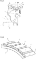
- FIG. 1 is a vertical sectional view of a decelerating apparatus according to the embodiment.
- FIG. 2 is a perspective view showing the arrangement of primary permanent magnets of the decelerating apparatus illustrated in FIG. 1 .
- FIGS. 3 and 4 are cross-sectional views showing magnetic circuits in the decelerating apparatus illustrated in FIG. 1 .
- FIG. 3 shows a braking state
- FIG. 4 shows a non-braking state.
- magnetic circuits are schematically indicated by solid lines, and directions of magnetic fluxes are indicated by arrows on the solid lines.
- a vertical section means a section along a rotation axis.
- a cross section means a section perpendicular to the rotation axis.
- the decelerating apparatus includes a cylindrical brake member 1, and a cylindrical magnet holder 2 placed at an inner side of the brake member 1.
- the brake member 1 is fixed to a rotary shaft 10 (for example, a propeller shaft, a drive shaft, or the like) of a vehicle via a rotor support 6 (see FIG. 1 ). Thereby, the brake member 1 rotates together with the rotary shaft 10.
- the solid arrows in FIGS. 3 and 4 indicate an example of the direction of rotation of the brake member 1.
- radiating fins 1a are provided (see FIG. 1 ). These radiating fins 1a function to cool down the brake member 1 directly.
- the magnetic holder 2 is paired with the brake member 1, and the magnetic holder 2 and the brake member 1 are coaxially arranged.
- the magnetic holder 2 is arranged to be slidable relative to a stator support 7, which is fixed to a non-rotative part 11 (for example, a transmission cover) of the vehicle, via a ring-shaped slide plate, for example. Accordingly, the magnetic holder 2 is held in a manner to be rotatable relative to the rotary shaft 10. In other words, the magnetic holder 2 is supported by the non-rotative part 11 via the stator support 7 so as not to rotate together with the rotary shaft 10.
- a plurality of primary permanent magnets 3 are fixed on the outer peripheral surface of the magnetic holder 2.
- the primary permanent magnets 3 are arranged in a circumferential direction of the brake member 1 and the magnet holder 2, which have a center on the rotary shaft 10, at regular intervals to face the inner peripheral surface 1b of the brake member 1 with a gap in between.
- the primary permanent magnets 3 are circumferentially arranged at regular intervals on the whole circumference of the magnetic holder 2.
- Each of the primary permanent magnets 3 has two opposite magnetic poles (a north pole (N) and a south pole (S)).
- Each of the primary permanent magnets 3 is positioned such that the magnetic poles (N and S) thereof are arranged in a radial direction of the brake member 1 and the magnetic holder 2, which have a center on the rotary shaft 10.
- the magnetic pole (N and S) arrangements of two circumferentially adjacent ones of the primary permanent magnets 3 are opposite to each other (see FIGS. 2 to 4 ).
- the magnet holder 2 is made of a ferromagnetic material (for example, carbon steel, cast iron or the like).
- a plurality of secondary permanent magnets 4 and a plurality of ferromagnetic pole pieces 5 are provided in the gap between the inner peripheral surface 1b of the brake member 1 and the outer peripheral surfaces of the primary permanent magnets 3.
- the secondary permanent magnets 4 are arranged in the circumferential direction of the brake member 1, which has a center on the rotary shaft 10.
- Each of the secondary permanent magnets 4 has two opposite magnetic poles (a north pole (N) and a south pole (S)) arranged in the circumferential direction.
- the magnetic pole (N and S) arrangements of two circumferentially adjacent ones of the secondary permanent magnets 4 are opposite to each other (see FIGS. 3 and 4 ).
- the pole pieces 5 are arranged between the secondary permanent magnets 4 such that each of the pole pieces 5 lies between and is in contact with two circumferentially adjacent ones of the secondary permanent magnets 4.
- the pitch of angular positions of the secondary permanent magnets 4 around the rotary shaft 10 corresponds to the pitch of angular positions of the primary permanent magnets 3 around the rotary shaft 10.
- the pitch of angular positions of the pole pieces 5 around the rotary shaft 10 corresponds to the pitch of angular positions of the primary permanent magnets 3 around the rotary shaft 10.
- Both sides of the secondary permanent magnets 4 and both sides of the pole pieces 5 are held by a ring-shaped stator 8.
- the secondary permanent magnets 4 and the pole pieces 5 are arranged on the whole circumference of the stator 8.
- the stator 8 is fixed to the stator support 7.
- the stator 8 is held via the stator support 7 so as to be rotatable relative to the rotary shaft 10 (see FIG. 1 ).
- the stator 8 is supported by the non-rotative part 11 of the vehicle via the stator support 7 so as not to rotate together with the rotary shaft 10 of the vehicle.
- each of the secondary permanent magnets 4 is trapezoidal in section perpendicular to the rotary shaft 10 (in cross section).
- each of the secondary permanent magnets 4 has an upper base 4a, a lower base 4b, and legs 4c, when viewed in cross section.
- the upper base 4a is located on the side near the brake member 1.
- the lower base 4b is longer than the upper base 4a and is located on the side near the primary permanent magnets 3.
- the legs 4c connect the upper base 4a and the lower base 4b.
- Each of the legs 4c forms an acute angle (greater than 0 degrees and smaller than 90 degrees) with the lower base 4b.
- each of the secondary permanent magnets 4 decreases in thickness (dimension in the radial direction) with decreasing distance from either end in the circumferential direction. In other words, in each of the secondary permanent magnets 4, the volume in both end portions in the circumferential direction is smaller than the volume in a central portion in the circumferential direction.
- each of the secondary permanent magnets 4 is substantially in the shape of an isosceles trapezoid in cross section. This means that each of the secondary permanent magnets 4 is designed to be in the shape of an isosceles trapezoid in cross section, and asymmetry caused by a dimension error or the like in the manufacturing process shall be tolerated.
- each of the pole pieces 5 is substantially pentagonal (in the shape of a home base) in section perpendicular to the rotary shaft 10 (in cross section).
- each of the pole pieces 5 has a base 5a facing the brake member 1, opposite sides 5b extending from end points of the base 5a toward the secondary permanent magnets 4, and oblique sides 5c that are in contact with the legs 4c of the secondary permanent magnets 4.
- each of the pole pieces 5 increases in thickness (dimension in the radial direction) with decreasing distance from the center in the circumferential direction.
- the maximum thickness of each of the pole pieces 5 is greater than the maximum thickness of each of the secondary permanent magnets 4.
- the volume in a central portion in the circumferential direction is greater than the volume in both end portions in the circumferential direction.
- primary air gaps G1 are provided between the secondary permanent magnets 4 such that each of the primary air gaps G1 lies between mutually facing ends, with respect to the circumferential direction, of two circumferentially adjacent secondary permanent magnets 4.
- the primary air gaps G1 are in contact with the surfaces of the pole pieces 5 near the primary permanent magnets 3. Since the maximum thickness of the pole pieces 5 is greater than the maximum thickness of the secondary permanent magnets 4, secondary air gaps G2 are formed between the circumferentially arranged pole pieces 5.
- Each of the secondary air gaps G2 is formed between the mutually facing sides 5b of two circumferentially adjacent pole pieces 5.
- the secondary air gaps G2 are in contact with the surfaces of the secondary permanent magnets 4 near the brake member 1 (the upper bases 4a).
- Each of the primary air gaps G1 is a gap between two adjacent secondary permanent magnets 4, and each of the primary air gaps G1 may be merely a space (air) or a non-magnetic material filled therein.
- each of the secondary air gaps G2 is a gap between two adjacent pole pieces 5, and each of the secondary air gaps G2 may be merely a space (air) or a non-magnetic material filled therein.
- the switching mechanism is configured to rotate the magnetic holder 2.
- the switching mechanism includes a lever 2a protruding from a side surface of the magnet holder 2 (see FIG. 1 ).
- a drive unit (not shown) including an air cylinder, an electric actuator, etc. is connected to the lever 2a via a link mechanism.
- the drive unit operates to rotate the magnet holder 2 and the primary permanent magnets 3 together.
- the primary permanent magnets 3, the secondary permanent magnets 4 and the pole pieces 5 are set in a position for the braking state or a position for the non-braking state.
- each of the primary permanent magnets 3 in the braking state, one pole piece 5 and circumferential end portions of two secondary permanent magnets 4 that are in contact with the pole piece 5 lie over, in the radial direction, each of the primary permanent magnets 3 (when viewed in the radial direction).
- each of the primary permanent magnets 3 is positioned across two circumferentially adjacent secondary permanent magnets 4 and faces the end portions (the corners between the lower ends 4b and the legs 4c (see FIG. 4 )) of the two adjacent secondary permanent magnets 4.
- each of the primary permanent magnets 3 has a magnetic pole (for example, N) same as the magnetic pole (for example, N) on the side of the primary permanent magnet 3 facing the secondary permanent magnets 4.
- N magnetic pole
- one pole piece 5 and circumferential end portions of two secondary personal magnets 4 that are in contact with the pole piece 5 lie over, in the radial direction, each of the primary permanent magnets 3 (when viewed in the radial direction).
- each of the primary permanent magnets 3 is positioned across two circumferentially adjacent secondary permanent magnets 4 and faces the end portions (the corners between the lower ends 4b and the legs 4c (see FIG.
- the end portions of the two adjacent secondary permanent magnets 4 overlapping the primary permanent magnet 3 have a magnetic pole (for example, S) opposite to the magnetic pole (for example, N) on the side of the primary permanent magnet 3 facing the secondary permanent magnets 4.
- a magnetic flux outgoing from the north pole of a first one of the two circumferentially adjacent primary permanent magnets 3 is superimposed on magnetic fluxes outgoing from the north poles of the two secondary permanent magnets 4 overlapping the first primary permanent magnet 3, and is conducted to a pole piece 5 overlapping the first primary permanent magnet 3 via an air gap G1.
- the magnetic flux conducted to the first pole piece 5 reaches the brake member 1 that is opposed to the pole piece 5 and the first primary permanent magnet 3.
- the magnetic flux that has reached the brake member 1 is conducted to another pole piece 5 overlapping the other (second) one of the two circumferentially adjacent primary permanent magnets 3 and reaches the south pole of the second primary permanent magnet 3.
- the magnetic flux outgoing from the north pole of the second primary permanent magnet 3 reaches the south pole of the first primary permanent magnet 3 via the magnetic holder 2.
- a magnetic flux outgoing from the north pole of a secondary permanent magnet 4 is superimposed on the magnetic flux outgoing from the north pole of the primary permanent magnet 3 overlapping the north pole of the secondary permanent magnet 4, and is conducted to a pole piece 5 that is in contact with the north pole of the secondary permanent magnet 4.
- the magnetic flux conducted to the pole piece 5 reaches the brake member 1 that is opposed to the pole piece 5 and the first primary permanent magnet 3.
- the magnetic flux that has reached the brake member 1 reaches the south pole of the secondary permanent magnet 4 via another pole piece 5 that is in contact with the south pole of the secondary permanent magnet 4.
- two circumferentially adjacent primary permanent magnets 3 form a magnetic circuit between these two circumferentially adjacent primary permanent magnets 3, two circumferentially adjacent pole pieces 5, the magnetic holder 2, and the brake member 1.
- a secondary permanent magnet 4 forms a magnetic circuit between this secondary permanent magnet 4, two circumferentially adjacent pole pieces 5, and the brake member 1.
- Such magnetic circuits are formed in the entire circumference.
- the direction of magnetic fluxes in adjacent magnetic circuits are opposite to each other
- the directions of magnetic fluxes in adjacent magnetic circuits are opposite to each other.
- the magnetic fluxes outgoing from the secondary permanent magnets 4 are superimposed on the magnetic fluxes outgoing from the primary permanent magnets 3, and thereby, enhanced magnetic fluxes reach the brake member 1. Accordingly, larger eddy-current flows are generated in the brake member 1 rotating together with the rotary shaft 10. Thus, a high brake torque can be produced.
- a magnetic flux outgoing from the north pole of a first one of two circumferentially adjacent primary permanent magnets 3 directly reaches the south pole of a secondary permanent magnet 4 overlapping the first primary permanent magnet 3.
- the magnetic flux outgoing from the north pole of the secondary permanent magnet 4 directly reaches the south pole of the other (second) one of the two adjacent primary permanent magnets 3 overlapping the north pole of the secondary permanent magnet 4.
- the magnetic flux outgoing from the north pole of the second primary permanent magnet 3 reaches the south pole of the first primary permanent magnet 3 via the magnet holder 2.
- a magnetic circuit is formed by two circumferentially adjacent primary permanent magnets 3 and a secondary permanent magnet 4 between these primary and secondary permanent magnets 3 and 4 and the magnet holder 2.
- Such magnetic circuits are formed in the entire circumference such that the directions of magnetic fluxes in adjacent magnetic circuits are opposite to each other.
- the magnetic fluxes outgoing from the primary and secondary permanent magnets 3 and 4 certainly do not reach the brake member 1. In other words, undesired magnetic flux leakage from the primary and secondary permanent magnets 3 and 4 to the brake member 1 can be prevented. In this state, accordingly, no eddy currents are generated on the brake member 1 rotating together with the rotary shaft 10, and unnecessary brake torque generation can be avoided.
- the brake member 1 is made of a ferromagnetic material (for example, carbon steel, cast iron, etc.).
- the inner peripheral surface 1b of the brake member 1 may be plated with copper, which is high in electric conductivity. When the inner peripheral surface 1b is plated with copper, the eddy currents generated thereon in the braking state become larger. This further enhances the brake torque.
- each of the secondary permanent magnets 4 is made trapezoidal in cross section such that the volume thereof is smaller in a portion closer to either end in the circumferential direction. Thereby, the magnetic flux outgoing from either end portion of each of the secondary permanent magnets 4 is decreased, and it is possible to prevent a magnetic flux leakage from a secondary permanent magnet 4 to an adjacent secondary permanent magnet 4 in the braking state.
- each of the pole pieces 5, which is positioned between two adjacent secondary permanent magnets 4, is made pentagonal in cross section such that the volume thereof is greater in a portion closer to the center in the circumferential direction.
- the pole piece 5 with such a shape certainly prevents a magnetic flux leakage from one of the two adjacent secondary permanent magnets 4 to the other secondary permanent magnet 4, and thereby, the magnetic fluxes outgoing from the secondary permanent magnets 4 can be certainly directed to the brake member 1 (see FIG. 3 ). Therefore, in the decelerating apparatus of the present embodiment, a brake torque can be effectively generated.
- the secondary air gaps G2 are provided between the circumferentially arranged pole pieces 5.
- the surfaces (upper bases 4a) of the secondary permanent magnets 4 which face the brake member 1 are exposed to the secondary air gaps G2.
- the surfaces of the secondary permanent magnets 4 facing the brake member 1 are not covered with any ferromagnetic material like the pole pieces 5. Accordingly, it is possible to lessen the possibility in the braking state that the magnetic fluxes outgoing from the secondary permanent magnets 4 return to the secondary permanent magnets 4 themselves without reaching the brake member 1 (self short-circuiting), and it is possible to effectively generate a braking torque in the braking state.
- the primary air gaps G1 are provided between the circumferentially adjacent secondary permanent magnets 4 such that each of the primary air gaps G1 is located between a primary permanent magnet 3 and a pole piece 5.
- the primary air gaps G1 may be spaces (air) or a non-magnetic material filled therein, and the primary air gaps G1 are relatively high in magnetic resistance. Accordingly, it is possible to lessen the possibility in the non-braking state that the magnetic fluxes outgoing from the primary permanent magnets 3 leak toward the pole pieces 5, and the magnetic fluxes outgoing from the primary permanent magnets 3 is conducted to the secondary permanent magnets 4 more certainly ( FIG. 4 ). As a result, unnecessary braking torque generation in the non-braking state can be effectively prevented.
- the primary air gaps G1 substantially do not prevent the primary and secondary permanent magnets 3 and 4 from generating magnetic circuits.
- two circumferentially adjacent primary magnets 3 and one secondary permanent magnet 4 form magnetic circuits between the brake member 1, the magnet holder 2, the circumferentially adjacent primary permanent magnets 3, and two circumferentially adjacent pole pieces 5.
- the magnetic flux outgoing from the north pole of one of the circumferentially adjacent primary permanent magnets 3 and the magnetic flux outgoing from the north pole of the secondary permanent magnet 4 are strengthened by each other and are effectively conducted to one of the adjacent pole pieces 5 via a primary air gap G1.
- the magnetic flux conducted to the pole piece 5 is conducted to the other pole piece 5 via the brake member 1 and thereafter is attracted by the south pole of the secondary magnet 4. Thereby, the magnetic flux effectively reaches the south pole of the other primary permanent magnet 3. Therefore, it is possible to ensure a sufficiently high volume of magnetic flux flowing through the primary and secondary permanent magnets 3, 4 and the pole pieces 5.
- the primary air gaps G1 serve as parts of the magnetic flux path though they have slight magnetic resistance.
- the eddy current decelerating apparatus according to the present disclosure can be effectively utilized as an auxiliary brake in any kind of vehicle.
Landscapes
- Engineering & Computer Science (AREA)
- Power Engineering (AREA)
- Dynamo-Electric Clutches, Dynamo-Electric Brakes (AREA)
Abstract
Description
- The present disclosure relates to a decelerating apparatus to be mounted in a vehicle, such as a truck, a bus or the like, as an auxiliary brake. More particularly, the present disclosure relates to an eddy current decelerating apparatus that uses permanent magnets to generate braking force.
- Generally, an eddy current decelerating apparatus includes a cylindrical brake member. The brake member is fixed to a rotary shaft of a vehicle. Typically, at an inner side of the brake member, a plurality of permanent magnets are arranged around the rotary shaft. In a gap between the inner peripheral surface of the brake member and the outer peripheral surfaces of the magnets, a plurality of pole pieces are arranged around the rotary shaft. By a switching mechanism, the positions of the magnets relative to the pole pieces are changed, and thereby, the eddy current decelerating apparatus is switched between a braking state and a non-braking state.
- Eddy current decelerating apparatuses are classified into an axially sliding type and a circumferentially rotating type, depending on how the switching mechanism changes the positions of the magnets. In an eddy current decelerating apparatus of an axially sliding type, as described in Japanese Utility Model No.
2557740 Patent Literature 1, in the braking state, the magnets are positioned inside the brake member, and magnetic fluxes outgoing from the magnets reach the brake member through the pole pieces. On the other hand, in the non-braking state, the magnets are moved along the axis of the rotary shaft by the actuator to go away from the brake member. Accordingly, magnetic fluxes outgoing from the magnets do not reach the brake member. - The eddy current decelerating apparatus of an axially sliding type requires a large space for the axial movements of the magnets. On the other hand, in an eddy current decelerating apparatus of a circumferential rotating type, as described in Japanese Patent Application Publication No.
2004-48963 - In the eddy current decelerating apparatus disclosed in
Patent Literature 2, in a braking state, each of the magnets almost entirely faces a pole piece, and a magnetic flux outgoing from the magnet reaches the brake member through the pole piece. Thus, magnetic circuits are formed between the magnets and the brake member. Accordingly, on the inner peripheral surface of the brake member rotating together with the rotary shaft, eddy currents are generated. As a result, breaking torque acts on the brake member, and the rotating speed of the rotary shaft is reduced. On the other hand, in a non-braking state, the magnets are circumferentially moved such that each of the magnets is positioned across two adjacent pole pieces. In this state, magnetic fluxes outgoing from the magnets substantially do not reach the brake member. Then, magnetic circuits are formed between the magnets and the pole pieces, and no magnetic circuits are formed between the magnets and the brake member. Accordingly, no eddy currents are generated on the inner peripheral surface of the brake member, and no braking torque is generated. - An eddy current decelerating apparatus disclosed in Japanese Patent Application No.
2004-32927 2007-82333 Patent Literatures -
- Patent Literature 1: Japanese Utility Model No.
2557740 - Patent Literature 2: Japanese Patent Application Publication No.
2004-48963 - Patent Literature 3: Japanese Patent Application Publication No.
2004-32927 - Patent Literature 4: Japanese Patent Application Publication No.
2007-82333 - In recent years, the performance of vehicles is being improved. Accordingly, decelerating apparatuses are required to generate higher braking torque at a time of braking. The decelerating apparatuses are also required to suppress unnecessary braking torque generation at a time of non-braking.
- An object of the present disclosure is to provide an eddy current decelerating apparatus that is capable of suppressing unnecessary braking torque generation at a time of non-braking and is capable of generating higher braking torque at a time of braking.
- An eddy current decelerating apparatus according to an embodiment of the present disclosure includes a cylindrical brake member, a plurality of primary permanent magnets, a cylindrical magnet holder, a plurality of secondary permanent magnets, a plurality of pole pieces, a stator, and a switching mechanism. The brake member is fixed to a rotary shaft. The primary permanent magnets are placed to face an inner or outer peripheral surface of the brake member with a gap in between. The primary permanent magnets are arranged in a circumferential direction of the brake member at regular intervals. Each of the primary permanent magnets has two opposite magnetic poles arranged in a radial direction of the brake member. The magnet holder holds the primary permanent magnets. The secondary permanent magnets are placed in the gap. The secondary permanent magnets are arranged in the circumferential direction at a pitch corresponding to the pitch of angular positions of the primary permanent magnets. Each of the secondary permanent magnets has two opposite magnetic poles arranged in the circumferential direction. The pole pieces are placed in the gap. Each of the pole pieces is positioned between and is in contact with two circumferentially adjacent ones of the secondary permanent magnets. The stator holds the secondary permanent magnets and the pole pieces. The switching mechanism is configured to rotate the magnet holder to switch the eddy current decelerating apparatus between a braking state and a non-braking state. Magnetic pole arrangements of two circumferentially adjacent ones of the primary permanent magnets are opposite to each other. Magnetic pole arrangements of two circumferentially adjacent ones of the secondary permanent magnets are opposite to each other. Each of the secondary permanent magnets has a trapezoidal cross-sectional shape including an upper base and a lower base. The upper base is on a side near the brake member. The lower base is on a side near the primary permanent magnets. The lower base is longer than the upper base. In the braking state, each of the secondary permanent magnets is positioned such that one end of the secondary permanent magnet with respect to the circumferential direction lies over, in the radial direction, one of the primary permanent magnets and such that the other end of the secondary permanent magnet with respect to the circumferential direction lies over, in the radial direction, another one of the primary permanent magnets. In this state, the one primary permanent magnet has, on a side near the secondary permanent magnet, a magnetic pole same as the magnetic pole of the one end of the secondary permanent magnet. The other permanent primary magnet has, on a side near the secondary permanent magnet, a magnetic pole same as the other end of the secondary permanent magnet. In the non-braking state, each of the secondary permanent magnets is positioned such that one end of the secondary permanent magnet with respect to the circumferential direction lies over, in the radial direction, one of the primary permanent magnets and such that the other end of the secondary permanent magnet with respect to the circumferential direction lies over, in the radial direction, another one of the primary permanent magnets. In this state, the one primary permanent magnet has, on a side near the secondary permanent magnet, a magnetic pole opposite to the magnetic pole of the one end of the secondary permanent magnet. The other primary magnet has, on a side near the secondary permanent magnet, a magnetic pole opposite to the other end of the secondary permanent magnet.
- An eddy current decelerating apparatus according to an embodiment of the present disclosure is capable of suppressing unnecessary braking torque generation at a time of non-braking and is capable of generating higher braking torque at a time of braking.
-
- [
FIG. 1] FIG. 1 is a vertical sectional view schematically illustrating a decelerating apparatus according to an embodiment of the present disclosure. - [
FIG. 2] FIG. 2 is a perspective view illustrating arrangement of primary permanent magnets in the decelerating apparatus illustrated inFIG. 1 . - [
FIG. 3] FIG. 3 is a cross-sectional view of magnetic circuits in the decelerating apparatus illustrated inFIG. 1 when the decelerating apparatus is in a braking state. - [
FIG. 4] FIG. 4 is a cross-sectional view of magnetic circuits in the decelerating apparatus illustrated inFIG. 1 when the decelerating apparatus is in a non-braking state. - An embodiment of the present disclosure will hereinafter be described. In the following description, the embodiment of the present disclosure will be described with examples; however, the present disclosure is not limited to the examples given below. In the following description, specific values and specific materials will be given as examples; however, the present disclosure is not limited to the examples.
- An eddy current decelerating apparatus according to an embodiment of the present disclosure includes a cylindrical brake member, a plurality of primary permanent magnets, a cylindrical magnet holder, a plurality of secondary permanent magnets, a plurality of pole pieces, a stator, and a switching mechanism. The brake member is fixed to a rotary shaft. The primary permanent magnets are placed to face an inner or outer peripheral surface of the brake member with a gap in between. The primary permanent magnets are arranged in a circumferential direction of the brake member at regular intervals. Each of the primary permanent magnets has two opposite magnetic poles arranged in a radial direction of the brake member. The magnetic holder holds the primary permanent magnets. The secondary permanent magnets are placed in the gap. The secondary permanent magnets are arranged in the circumferential direction at a pitch corresponding to the pitch of angular positions of the primary permanent magnets. Each of the secondary permanent magnets has two opposite magnetic poles arranged in the circumferential direction. The pole pieces are placed in the gap. Each of the pole pieces is positioned between and is in contact with two circumferentially adjacent ones of the secondary permanent magnets. The stator holds the secondary permanent magnets and the pole pieces. The switching mechanism is configured to rotate the magnet holder to switch the decelerating apparatus between a braking state and a non-braking state. Magnetic pole arrangements of two circumferentially adjacent ones of the primary permanent magnets are opposite to each other. Magnetic pole arrangements of two circumferentially adjacent ones of the secondary permanent magnets are opposite to each other. Each of the secondary permanent magnets has a trapezoidal cross-sectional shape including an upper base and a lower base. The upper base is on a side near the brake member. The lower base is on a side near the primary permanent magnets. The lower base is longer than the upper base. In the braking state, each of the secondary permanent magnets is positioned such that one end of the secondary permanent magnet with respect to the circumferential direction lies over, in the radial direction, one of the primary permanent magnets and such that the other end of the secondary permanent magnet with respect to the circumferential direction lies over, in the radial direction, another one of the primary permanent magnets. In this state, the one primary permanent magnet has, on a side near the secondary permanent magnet, a magnetic pole same as the magnetic pole of the one end of the secondary permanent magnet. The other primary magnet has, on a side near the secondary permanent magnet, a magnetic pole same as the other end of the secondary permanent magnet. In the non-braking state, each of the secondary permanent magnets is positioned such that one end of the secondary permanent magnet with respect to the circumferential direction lies over, in the radial direction, one of the primary permanent magnets and such that the other end of the secondary permanent magnet with respect to the circumferential direction lies over, in the radial direction, another one of the primary permanent magnets. In this state, the one primary permanent magnet has, on a side near the secondary permanent magnet, a magnetic pole opposite to the magnetic pole of the one end of the secondary permanent magnet. The other primary magnet has, on a side near the secondary permanent magnet, a magnetic pole opposite to the other end of the secondary permanent magnet.
- In the decelerating apparatus according to the present embodiment, the magnet holder is rotated relative to the stator by the switching mechanism, and thereby, the decelerating apparatus is switched between the braking state and the non-braking state. Each of the secondary permanent magnets has a trapezoidal cross-sectional shape, and therefore, in either of the braking state or the non-braking state, one pole piece and circumferential end portions of two secondary permanent magnets in contact with the pole piece lie over, in the radial direction, each of the primary permanent magnets. In other words, when the circumferentially arranged secondary permanent magnets are viewed from the inner periphery or the outer periphery, the end portions of the secondary permanent magnets lie over the primary permanent magnets. In the braking state, each end portion of each of the secondary permanent magnets has a magnetic pole (for example, N) same as the magnetic pole (for example, N) of the side of the primary permanent magnet facing the end portion of the secondary permanent magnet. On the other hand, in the non-braking state, each end portion of each of the secondary permanent magnets has a magnetic pole (for example, S) opposite to the magnetic pole (for example, N) of the side of the primary permanent magnet facing the end portion of the secondary permanent magnet. In the present embodiment, cross section means a section perpendicular to the rotation axis.
- In the braking state, two circumferentially adjacent primary permanent magnets form a magnetic circuit between the two adjacent primary permanent magnets, two circumferentially adjacent pole pieces, the magnetic holder, and the brake member. Further, one secondary permanent magnet forms a magnetic circuit between the secondary permanent magnet, two circumferentially adjacent pole pieces, and the brake member.
- Accordingly, in the decelerating apparatus of the present embodiment, in the braking state, a magnetic flux outgoing from the secondary permanent magnets is superimposed on a magnetic flux outgoing from the primary permanent magnets, and thereby, a strengthened magnetic flux reaches the brake member. Therefore, large eddy currents are generated on the brake member rotating together with the rotary shaft. This makes it possible to achieve high braking torque.
- On the other hand, in the non-braking state, two circumferentially adjacent primary permanent magnets and one secondary permanent magnet mainly form a magnetic circuit between the two adjacent primary permanent magnets, the secondary permanent magnet, and the magnet holder.
- Accordingly, in the decelerating apparatus of the present embodiment, in the braking state, there is only little magnetic flux leakage from the primary and secondary permanent magnets to the brake member. Accordingly, only very small eddy currents are generated on the brake member rotating together with the rotary shaft, and it is possible to suppress unnecessary braking torque generation.
- In a typical example of the decelerating apparatus of the present embodiment, the plurality of primary permanent magnets are arranged at an inner side of the brake member to face an inner peripheral surface of the brake member with a gap in between. In this case, the plurality of secondary primary magnets and the plurality of pole pieces are arranged in the gap between the inner peripheral surface of the brake member and the outer peripheral surfaces of the primary permanent magnets. The pitch of angular positions of the secondary permanent magnets around the rotary shaft is the same as the pitch of angular positions of the primary permanent magnets around the rotary shaft. The pitch of angular positions of the pole pieces around the rotation axis of the rotary shaft is the same as the pitch of angular positions of the primary permanent magnets around the rotary shaft.
- In the decelerating apparatus of the present embodiment, each of the secondary permanent magnets, which are trapezoidal in cross section, may have round corners. Specifically, in the trapezoidal cross section of each of the secondary permanent magnets, the upper base may be connected to legs via circular arcs, and/or the lower base may be connected to the legs via circular arcs. Alternatively, in the trapezoidal cross section of each of the secondary permanent magnets, the corners may be beveled. In other words, in the trapezoidal cross section of each of the secondary permanent magnets, there may be a straight line between the upper base and each of the legs and/or between the lower base and each of the legs.
- In the typical example of the decelerating apparatus of the present embodiment, primary air gaps are provided between the secondary permanent magnets such that each of the primary air gaps lies between mutually facing ends, with respect to the circumferential direction, of two circumferentially adjacent ones of the secondary permanent magnets. The primary air gaps serve as some magnetic resistance. In the braking state, two circumferentially adjacent primary permanent magnets and one secondary permanent form a magnetic circuit between the two adjacent primary permanent magnets, two circumferentially adjacent pole pieces, the magnet holder, and the brake member. Then, a magnetic flux outgoing from the north pole of one of the two adjacent primary permanent magnets and a magnetic flux outgoing from the north pole of the secondary permanent magnet are strengthened by each other and effectively conducted to one of the two adjacent pole pieces through one primary air gap. The magnetic flux which has been conducted to the pole piece through the primary air gap is attracted by the south pole of the secondary permanent magnet and effectively reaches the south pole of the other of the two adjacent primary permanent magnets through another primary air gap. Thus, the primary air gaps also serve as parts of the magnetic flux path. Therefore, it is possible to ensure a sufficiently high volume of magnetic flux flowing through the primary and secondary permanent magnets and the pole pieces.
- In the typical example of the decelerating apparatus of the present embodiment, secondary air gaps are provided between the pole pieces such that each of the secondary air gaps lies between mutually facing ends, with respect to the circumferential direction, of two circumferentially adjacent ones of the pole pieces. In the braking state, each of the secondary permanent magnets forms a magnetic circuit between the secondary permanent magnet, two circumferentially adjacent pole pieces, and the brake member. In this state, the secondary air gap between the two adjacent pole pieces effectively prevents short-circuiting from one of the pole pieces to the other pole piece. Also, self short-circuiting of the secondary permanent magnet can be prevented.
- An eddy current decelerating apparatus according to an embodiment of the present disclosure will hereinafter be described in detail.
-
FIG. 1 is a vertical sectional view of a decelerating apparatus according to the embodiment.FIG. 2 is a perspective view showing the arrangement of primary permanent magnets of the decelerating apparatus illustrated inFIG. 1 .FIGS. 3 and 4 are cross-sectional views showing magnetic circuits in the decelerating apparatus illustrated inFIG. 1 .FIG. 3 shows a braking state, andFIG. 4 shows a non-braking state. InFIGS. 3 and 4 , magnetic circuits are schematically indicated by solid lines, and directions of magnetic fluxes are indicated by arrows on the solid lines. In this specification, a vertical section means a section along a rotation axis. A cross section means a section perpendicular to the rotation axis. - With reference to
FIGS. 1 to 4 , the decelerating apparatus includes acylindrical brake member 1, and acylindrical magnet holder 2 placed at an inner side of thebrake member 1. Thebrake member 1 is fixed to a rotary shaft 10 (for example, a propeller shaft, a drive shaft, or the like) of a vehicle via a rotor support 6 (seeFIG. 1 ). Thereby, thebrake member 1 rotates together with therotary shaft 10. The solid arrows inFIGS. 3 and 4 indicate an example of the direction of rotation of thebrake member 1. On the outer peripheral surface of thebrake member 1, radiatingfins 1a are provided (seeFIG. 1 ). These radiatingfins 1a function to cool down thebrake member 1 directly. - The
magnetic holder 2 is paired with thebrake member 1, and themagnetic holder 2 and thebrake member 1 are coaxially arranged. Themagnetic holder 2 is arranged to be slidable relative to astator support 7, which is fixed to a non-rotative part 11 (for example, a transmission cover) of the vehicle, via a ring-shaped slide plate, for example. Accordingly, themagnetic holder 2 is held in a manner to be rotatable relative to therotary shaft 10. In other words, themagnetic holder 2 is supported by thenon-rotative part 11 via thestator support 7 so as not to rotate together with therotary shaft 10. - As shown in
FIGS. 1 and 2 , a plurality of primarypermanent magnets 3 are fixed on the outer peripheral surface of themagnetic holder 2. The primarypermanent magnets 3 are arranged in a circumferential direction of thebrake member 1 and themagnet holder 2, which have a center on therotary shaft 10, at regular intervals to face the innerperipheral surface 1b of thebrake member 1 with a gap in between. In other words, the primarypermanent magnets 3 are circumferentially arranged at regular intervals on the whole circumference of themagnetic holder 2. Each of the primarypermanent magnets 3 has two opposite magnetic poles (a north pole (N) and a south pole (S)). Each of the primarypermanent magnets 3 is positioned such that the magnetic poles (N and S) thereof are arranged in a radial direction of thebrake member 1 and themagnetic holder 2, which have a center on therotary shaft 10. The magnetic pole (N and S) arrangements of two circumferentially adjacent ones of the primarypermanent magnets 3 are opposite to each other (seeFIGS. 2 to 4 ). Themagnet holder 2 is made of a ferromagnetic material (for example, carbon steel, cast iron or the like). - As shown in
FIGS. 1 ,3 and 4 , in the gap between the innerperipheral surface 1b of thebrake member 1 and the outer peripheral surfaces of the primarypermanent magnets 3, a plurality of secondarypermanent magnets 4 and a plurality offerromagnetic pole pieces 5 are provided. The secondarypermanent magnets 4 are arranged in the circumferential direction of thebrake member 1, which has a center on therotary shaft 10. Each of the secondarypermanent magnets 4 has two opposite magnetic poles (a north pole (N) and a south pole (S)) arranged in the circumferential direction. The magnetic pole (N and S) arrangements of two circumferentially adjacent ones of the secondarypermanent magnets 4 are opposite to each other (seeFIGS. 3 and 4 ). Thepole pieces 5 are arranged between the secondarypermanent magnets 4 such that each of thepole pieces 5 lies between and is in contact with two circumferentially adjacent ones of the secondarypermanent magnets 4. The pitch of angular positions of the secondarypermanent magnets 4 around therotary shaft 10 corresponds to the pitch of angular positions of the primarypermanent magnets 3 around therotary shaft 10. The pitch of angular positions of thepole pieces 5 around therotary shaft 10 corresponds to the pitch of angular positions of the primarypermanent magnets 3 around therotary shaft 10. - Both sides of the secondary
permanent magnets 4 and both sides of thepole pieces 5 are held by a ring-shapedstator 8. The secondarypermanent magnets 4 and thepole pieces 5 are arranged on the whole circumference of thestator 8. Thestator 8 is fixed to thestator support 7. Thus, thestator 8 is held via thestator support 7 so as to be rotatable relative to the rotary shaft 10 (seeFIG. 1 ). In other words, thestator 8 is supported by thenon-rotative part 11 of the vehicle via thestator support 7 so as not to rotate together with therotary shaft 10 of the vehicle. - As shown in
FIGS. 3 and 4 , each of the secondarypermanent magnets 4 is trapezoidal in section perpendicular to the rotary shaft 10 (in cross section). As shown inFIG. 4 , each of the secondarypermanent magnets 4 has anupper base 4a, alower base 4b, andlegs 4c, when viewed in cross section. Theupper base 4a is located on the side near thebrake member 1. Thelower base 4b is longer than theupper base 4a and is located on the side near the primarypermanent magnets 3. Thelegs 4c connect theupper base 4a and thelower base 4b. Each of thelegs 4c forms an acute angle (greater than 0 degrees and smaller than 90 degrees) with thelower base 4b. When theleg 4c and thebase 4b is connected by a circular arc or another straight line, the extended line of theleg 4c forms an acute angle with the extended line of thelower base 4b. When viewed in cross section, each of the secondarypermanent magnets 4 decreases in thickness (dimension in the radial direction) with decreasing distance from either end in the circumferential direction. In other words, in each of the secondarypermanent magnets 4, the volume in both end portions in the circumferential direction is smaller than the volume in a central portion in the circumferential direction. - It is preferred that each of the secondary
permanent magnets 4 is substantially in the shape of an isosceles trapezoid in cross section. This means that each of the secondarypermanent magnets 4 is designed to be in the shape of an isosceles trapezoid in cross section, and asymmetry caused by a dimension error or the like in the manufacturing process shall be tolerated. - As shown in
FIG. 4 , each of thepole pieces 5 is substantially pentagonal (in the shape of a home base) in section perpendicular to the rotary shaft 10 (in cross section). When viewed in cross section, each of thepole pieces 5 has abase 5a facing thebrake member 1,opposite sides 5b extending from end points of thebase 5a toward the secondarypermanent magnets 4, andoblique sides 5c that are in contact with thelegs 4c of the secondarypermanent magnets 4. When viewed in cross section, each of thepole pieces 5 increases in thickness (dimension in the radial direction) with decreasing distance from the center in the circumferential direction. The maximum thickness of each of thepole pieces 5 is greater than the maximum thickness of each of the secondarypermanent magnets 4. In each of thepole pieces 5, the volume in a central portion in the circumferential direction is greater than the volume in both end portions in the circumferential direction. - As shown in
FIG. 4 , primary air gaps G1 are provided between the secondarypermanent magnets 4 such that each of the primary air gaps G1 lies between mutually facing ends, with respect to the circumferential direction, of two circumferentially adjacent secondarypermanent magnets 4. The primary air gaps G1 are in contact with the surfaces of thepole pieces 5 near the primarypermanent magnets 3. Since the maximum thickness of thepole pieces 5 is greater than the maximum thickness of the secondarypermanent magnets 4, secondary air gaps G2 are formed between the circumferentially arrangedpole pieces 5. Each of the secondary air gaps G2 is formed between the mutually facingsides 5b of two circumferentiallyadjacent pole pieces 5. The secondary air gaps G2 are in contact with the surfaces of the secondarypermanent magnets 4 near the brake member 1 (theupper bases 4a). Each of the primary air gaps G1 is a gap between two adjacent secondarypermanent magnets 4, and each of the primary air gaps G1 may be merely a space (air) or a non-magnetic material filled therein. Similarly, each of the secondary air gaps G2 is a gap between twoadjacent pole pieces 5, and each of the secondary air gaps G2 may be merely a space (air) or a non-magnetic material filled therein. - The switching mechanism is configured to rotate the
magnetic holder 2. The switching mechanism includes alever 2a protruding from a side surface of the magnet holder 2 (seeFIG. 1 ). A drive unit (not shown) including an air cylinder, an electric actuator, etc. is connected to thelever 2a via a link mechanism. When switching from the braking state to the non-braking state and vice versa, the drive unit operates to rotate themagnet holder 2 and the primarypermanent magnets 3 together. Thereby, the primarypermanent magnets 3, the secondarypermanent magnets 4 and thepole pieces 5 are set in a position for the braking state or a position for the non-braking state. - Referring to
FIG. 3 , in the braking state, onepole piece 5 and circumferential end portions of two secondarypermanent magnets 4 that are in contact with thepole piece 5 lie over, in the radial direction, each of the primary permanent magnets 3 (when viewed in the radial direction). In other words, each of the primarypermanent magnets 3 is positioned across two circumferentially adjacent secondarypermanent magnets 4 and faces the end portions (the corners between the lower ends 4b and thelegs 4c (seeFIG. 4 )) of the two adjacent secondarypermanent magnets 4. At the time, the end portions of the two adjacent secondarypermanent magnets 4 overlapping the primarypermanent magnet 3 have a magnetic pole (for example, N) same as the magnetic pole (for example, N) on the side of the primarypermanent magnet 3 facing the secondarypermanent magnets 4. Referring toFIG. 4 , in the non-braking state, as in the braking state, onepole piece 5 and circumferential end portions of two secondarypersonal magnets 4 that are in contact with thepole piece 5 lie over, in the radial direction, each of the primary permanent magnets 3 (when viewed in the radial direction). In other words, each of the primarypermanent magnets 3 is positioned across two circumferentially adjacent secondarypermanent magnets 4 and faces the end portions (the corners between the lower ends 4b and thelegs 4c (seeFIG. 4 )) of the two adjacent secondarypermanent magnets 4. At the time, the end portions of the two adjacent secondarypermanent magnets 4 overlapping the primarypermanent magnet 3 have a magnetic pole (for example, S) opposite to the magnetic pole (for example, N) on the side of the primarypermanent magnet 3 facing the secondarypermanent magnets 4. By rotating themagnetic holder 2 relative to thestator 8 by an angle corresponding to the pitch of angular positions of the primary permanent magnets 3 (the secondarypermanent magnets 4 and the pole pieces 5), switching between the braking state and the non-braking state can be performed. - As shown in
FIG. 3 , in the braking state, a magnetic flux outgoing from the north pole of a first one of the two circumferentially adjacent primarypermanent magnets 3 is superimposed on magnetic fluxes outgoing from the north poles of the two secondarypermanent magnets 4 overlapping the first primarypermanent magnet 3, and is conducted to apole piece 5 overlapping the first primarypermanent magnet 3 via an air gap G1. The magnetic flux conducted to thefirst pole piece 5 reaches thebrake member 1 that is opposed to thepole piece 5 and the first primarypermanent magnet 3. The magnetic flux that has reached thebrake member 1 is conducted to anotherpole piece 5 overlapping the other (second) one of the two circumferentially adjacent primarypermanent magnets 3 and reaches the south pole of the second primarypermanent magnet 3. The magnetic flux outgoing from the north pole of the second primarypermanent magnet 3 reaches the south pole of the first primarypermanent magnet 3 via themagnetic holder 2. - Meanwhile, a magnetic flux outgoing from the north pole of a secondary
permanent magnet 4 is superimposed on the magnetic flux outgoing from the north pole of the primarypermanent magnet 3 overlapping the north pole of the secondarypermanent magnet 4, and is conducted to apole piece 5 that is in contact with the north pole of the secondarypermanent magnet 4. The magnetic flux conducted to thepole piece 5 reaches thebrake member 1 that is opposed to thepole piece 5 and the first primarypermanent magnet 3. The magnetic flux that has reached thebrake member 1 reaches the south pole of the secondarypermanent magnet 4 via anotherpole piece 5 that is in contact with the south pole of the secondarypermanent magnet 4. - Thus, in the braking state, two circumferentially adjacent primary
permanent magnets 3 form a magnetic circuit between these two circumferentially adjacent primarypermanent magnets 3, two circumferentiallyadjacent pole pieces 5, themagnetic holder 2, and thebrake member 1. Also, a secondarypermanent magnet 4 forms a magnetic circuit between this secondarypermanent magnet 4, two circumferentiallyadjacent pole pieces 5, and thebrake member 1. Such magnetic circuits are formed in the entire circumference. In this regard, concerning the magnetic circuits formed by the primarypermanent magnets 3, the direction of magnetic fluxes in adjacent magnetic circuits are opposite to each other, and concerning the magnetic circuits formed by the secondarypermanent magnets 4, the directions of magnetic fluxes in adjacent magnetic circuits are opposite to each other. - In a state in which there is a relative difference between the rotating speed of the primary and secondary
permanent magnets brake member 1, when magnetic fields formed by the primary and secondarypermanent magnets brake member 1, eddy currents are generated on the innerperipheral surface 1b of thebrake member 1 that is opposed to the primarypermanent magnets 3. By the interaction between these eddy currents and the density of magnetic fluxes outgoing from the primary and secondarypermanent magnets brake member 1 rotating together with therotary shaft 10. - Thus, in the decelerating apparatus of the present embodiment, in the braking state, the magnetic fluxes outgoing from the secondary
permanent magnets 4 are superimposed on the magnetic fluxes outgoing from the primarypermanent magnets 3, and thereby, enhanced magnetic fluxes reach thebrake member 1. Accordingly, larger eddy-current flows are generated in thebrake member 1 rotating together with therotary shaft 10. Thus, a high brake torque can be produced. - On the other hand, in the non-braking state, as shown in
FIG. 4 , a magnetic flux outgoing from the north pole of a first one of two circumferentially adjacent primarypermanent magnets 3 directly reaches the south pole of a secondarypermanent magnet 4 overlapping the first primarypermanent magnet 3. The magnetic flux outgoing from the north pole of the secondarypermanent magnet 4 directly reaches the south pole of the other (second) one of the two adjacent primarypermanent magnets 3 overlapping the north pole of the secondarypermanent magnet 4. The magnetic flux outgoing from the north pole of the second primarypermanent magnet 3 reaches the south pole of the first primarypermanent magnet 3 via themagnet holder 2. - Thus, in the non-braking state, a magnetic circuit is formed by two circumferentially adjacent primary
permanent magnets 3 and a secondarypermanent magnet 4 between these primary and secondarypermanent magnets magnet holder 2. Such magnetic circuits are formed in the entire circumference such that the directions of magnetic fluxes in adjacent magnetic circuits are opposite to each other. - Therefore, in the decelerating apparatus of the present embodiment, in the non-braking state, the magnetic fluxes outgoing from the primary and secondary
permanent magnets brake member 1. In other words, undesired magnetic flux leakage from the primary and secondarypermanent magnets brake member 1 can be prevented. In this state, accordingly, no eddy currents are generated on thebrake member 1 rotating together with therotary shaft 10, and unnecessary brake torque generation can be avoided. - For example, the
brake member 1 is made of a ferromagnetic material (for example, carbon steel, cast iron, etc.). The innerperipheral surface 1b of thebrake member 1 may be plated with copper, which is high in electric conductivity. When the innerperipheral surface 1b is plated with copper, the eddy currents generated thereon in the braking state become larger. This further enhances the brake torque. - Regarding a permanent magnet, generally, a magnetic flux outgoing from the central portion with respect to the direction of magnetic pole arrangement (N and S arrangement) goes less straight, and a magnetic flux outgoing from either end portion with respect to the direction of magnetic pole arrangement goes more straight. In consideration of this fact, each of the secondary
permanent magnets 4 is made trapezoidal in cross section such that the volume thereof is smaller in a portion closer to either end in the circumferential direction. Thereby, the magnetic flux outgoing from either end portion of each of the secondarypermanent magnets 4 is decreased, and it is possible to prevent a magnetic flux leakage from a secondarypermanent magnet 4 to an adjacent secondarypermanent magnet 4 in the braking state. Further, each of thepole pieces 5, which is positioned between two adjacent secondarypermanent magnets 4, is made pentagonal in cross section such that the volume thereof is greater in a portion closer to the center in the circumferential direction. In the braking state, thepole piece 5 with such a shape certainly prevents a magnetic flux leakage from one of the two adjacent secondarypermanent magnets 4 to the other secondarypermanent magnet 4, and thereby, the magnetic fluxes outgoing from the secondarypermanent magnets 4 can be certainly directed to the brake member 1 (seeFIG. 3 ). Therefore, in the decelerating apparatus of the present embodiment, a brake torque can be effectively generated. - In the decelerating apparatus of the present embodiment, the secondary air gaps G2 are provided between the circumferentially arranged
pole pieces 5. The surfaces (upper bases 4a) of the secondarypermanent magnets 4 which face thebrake member 1 are exposed to the secondary air gaps G2. In other words, the surfaces of the secondarypermanent magnets 4 facing thebrake member 1 are not covered with any ferromagnetic material like thepole pieces 5. Accordingly, it is possible to lessen the possibility in the braking state that the magnetic fluxes outgoing from the secondarypermanent magnets 4 return to the secondarypermanent magnets 4 themselves without reaching the brake member 1 (self short-circuiting), and it is possible to effectively generate a braking torque in the braking state. - In the decelerating apparatus of the present embodiment, the primary air gaps G1 are provided between the circumferentially adjacent secondary
permanent magnets 4 such that each of the primary air gaps G1 is located between a primarypermanent magnet 3 and apole piece 5. As mentioned above, the primary air gaps G1 may be spaces (air) or a non-magnetic material filled therein, and the primary air gaps G1 are relatively high in magnetic resistance. Accordingly, it is possible to lessen the possibility in the non-braking state that the magnetic fluxes outgoing from the primarypermanent magnets 3 leak toward thepole pieces 5, and the magnetic fluxes outgoing from the primarypermanent magnets 3 is conducted to the secondarypermanent magnets 4 more certainly (FIG. 4 ). As a result, unnecessary braking torque generation in the non-braking state can be effectively prevented. - In the braking state, the primary air gaps G1 substantially do not prevent the primary and secondary
permanent magnets primary magnets 3 and one secondarypermanent magnet 4 form magnetic circuits between thebrake member 1, themagnet holder 2, the circumferentially adjacent primarypermanent magnets 3, and two circumferentiallyadjacent pole pieces 5. In this state, the magnetic flux outgoing from the north pole of one of the circumferentially adjacent primarypermanent magnets 3 and the magnetic flux outgoing from the north pole of the secondarypermanent magnet 4 are strengthened by each other and are effectively conducted to one of theadjacent pole pieces 5 via a primary air gap G1. The magnetic flux conducted to thepole piece 5 is conducted to theother pole piece 5 via thebrake member 1 and thereafter is attracted by the south pole of thesecondary magnet 4. Thereby, the magnetic flux effectively reaches the south pole of the other primarypermanent magnet 3. Therefore, it is possible to ensure a sufficiently high volume of magnetic flux flowing through the primary and secondarypermanent magnets pole pieces 5. Thus, in the braking state, the primary air gaps G1 serve as parts of the magnetic flux path though they have slight magnetic resistance. - The present disclosure is not limited to the above-described embodiment, and various changes and modifications may be made to the embodiment without departing from the scope of the present disclosure.
- The eddy current decelerating apparatus according to the present disclosure can be effectively utilized as an auxiliary brake in any kind of vehicle.
-
- 1: brake member
- 1b: inner peripheral surface of brake member
- 2: magnet holder
- 3: primary permanent magnet
- 4: secondary permanent magnet
- 4a: upper base of secondary permanent magnet
- 4b: lower base of secondary permanent magnet
- 4c: leg of secondary permanent magnet
- 5: pole piece
- 8: stator
- 10: rotary shaft
Claims (3)
- An eddy current decelerating apparatus comprising:a cylindrical brake member fixed to a rotary shaft;a plurality of primary permanent magnets that are arranged in a circumferential direction of the brake member at regular intervals to face an inner or outer peripheral surface of the brake member with a gap in between, each of the primary permanent magnets having two opposite magnetic poles arranged in a radial direction of the brake member;a cylindrical magnet holder holding the primary permanent magnets;a plurality of secondary permanent magnets that are placed in the gap to be arranged in the circumferential direction at a pitch corresponding to a pitch of angular positions of the primary permanent magnets, each of the secondary permanent magnets having two opposite magnetic poles arranged in the circumferential direction;a plurality of pole pieces that are placed in the gap such that each of the pole pieces is positioned between and is in contact with two circumferentially adjacent ones of the secondary permanent magnets;a stator holding the secondary permanent magnets and the pole pieces; anda switching mechanism configured to rotate the magnet holder to switch the eddy current decelerating apparatus between a braking state and a non-braking state;wherein:magnetic pole arrangements of two circumferentially adjacent ones of the primary permanent magnets are opposite to each other;magnetic pole arrangements of two circumferentially adjacent ones of the secondary permanent magnets are opposite to each other;each of the secondary permanent magnets has a trapezoidal cross-sectional shape including an upper base on a side near the brake member and a lower base on a side near the primary permanent magnets, the lower base being longer than the upper base;in the braking state, each of the secondary permanent magnets is positioned such that one end of the secondary permanent magnet with respect to the circumferential direction lies over, in the radial direction, one of the primary permanent magnets that has, on a side near the secondary permanent magnet, a magnetic pole same as the magnetic pole of the one end of the secondary permanent magnet and such that the other end of the secondary permanent magnet with respect to the circumferential direction lies over, in the radial direction, another one of the primary permanent magnets that has, on a side near the secondary permanent magnet, a magnetic pole same as the other end of the secondary permanent magnet; andin the non-braking state, each of the secondary permanent magnets are positioned such that one end of the secondary permanent magnet with respect to the circumferential direction lies over, in the radial direction, one of the primary permanent magnets that has, on a side near the secondary permanent magnet, a magnetic pole opposite to the magnetic pole of the one end of the secondary permanent magnet and such that the other end of the secondary permanent magnet with respect to the circumferential direction lies over, in the radial direction, another one of the primary permanent magnets that has, on a side near the secondary permanent magnet, a magnetic pole opposite to the other end of the secondary permanent magnet.
- The eddy current decelerating apparatus according to claim 1, wherein primary air gaps are provided between the secondary permanent magnets such that each of the primary air gaps lies between mutually facing ends, with respect to the circumferential direction, of two circumferentially adjacent ones of the secondary permanent magnets.
- The eddy current decelerating apparatus according to claim 1 or 2, wherein secondary air gaps are provided between the pole pieces such that each of the secondary air gaps lies between mutually facing ends, with respect to the circumferential direction, of two circumferentially adjacent ones of the pole pieces.
Applications Claiming Priority (2)
| Application Number | Priority Date | Filing Date | Title |
|---|---|---|---|
| JP2018012117 | 2018-01-29 | ||
| PCT/JP2019/001943 WO2019146608A1 (en) | 2018-01-29 | 2019-01-23 | Eddy current-type speed-reduction device |
Publications (3)
| Publication Number | Publication Date |
|---|---|
| EP3748824A1 true EP3748824A1 (en) | 2020-12-09 |
| EP3748824A4 EP3748824A4 (en) | 2021-10-27 |
| EP3748824B1 EP3748824B1 (en) | 2024-03-06 |
Family
ID=67394637
Family Applications (1)
| Application Number | Title | Priority Date | Filing Date |
|---|---|---|---|
| EP19744431.8A Active EP3748824B1 (en) | 2018-01-29 | 2019-01-23 | Eddy current-type speed-reduction device |
Country Status (6)
| Country | Link |
|---|---|
| US (1) | US11165326B2 (en) |
| EP (1) | EP3748824B1 (en) |
| JP (1) | JP6852814B2 (en) |
| KR (1) | KR102378402B1 (en) |
| CN (1) | CN111656657B (en) |
| WO (1) | WO2019146608A1 (en) |
Cited By (1)
| Publication number | Priority date | Publication date | Assignee | Title |
|---|---|---|---|---|
| WO2024246134A1 (en) * | 2023-05-30 | 2024-12-05 | Safran Landing Systems | Magnetic braking device for a braked wheel of an aircraft landing gear |
Families Citing this family (9)
| Publication number | Priority date | Publication date | Assignee | Title |
|---|---|---|---|---|
| DE102019134054A1 (en) | 2019-12-11 | 2021-06-17 | Rosen Swiss Ag | Pig, in particular inspection or cleaning pig |
| JP7372539B2 (en) * | 2020-01-10 | 2023-11-01 | 日本製鉄株式会社 | Eddy current reduction gear |
| JP7290831B2 (en) * | 2020-01-10 | 2023-06-14 | 日本製鉄株式会社 | Eddy current reduction gear |
| CN114683864B (en) * | 2020-12-30 | 2023-11-03 | 中国航天科工飞航技术研究院(中国航天海鹰机电技术研究院) | Eddy current brake for vehicle, braking device and method and vehicle |
| US12249869B1 (en) * | 2021-04-14 | 2025-03-11 | Variant Motion Inc | Permanent magnet electric motor |
| CN120513571A (en) * | 2023-01-31 | 2025-08-19 | 日本制铁株式会社 | Eddy current reduction gear |
| TWI867433B (en) * | 2023-02-17 | 2024-12-21 | 張力 | Deceleration brake mechanism |
| CN116653616A (en) * | 2023-04-12 | 2023-08-29 | 余姚市机器人研究中心 | Novel hybrid excitation line vortex brake and rail vehicle |
| CN121124443B (en) * | 2025-11-12 | 2026-01-27 | 上海冠群贝东实业有限公司 | Explosion-proof permanent magnet motor with magnetic vortex and friction composite braking device |
Family Cites Families (17)
| Publication number | Priority date | Publication date | Assignee | Title |
|---|---|---|---|---|
| JP2557740B2 (en) | 1990-11-29 | 1996-11-27 | 五洋建設株式会社 | Tendon tension introduction method for vertical mooring offshore floating platform |
| JP2557740Y2 (en) | 1992-02-19 | 1997-12-17 | いすゞ自動車株式会社 | Structure of fixed frame of eddy current type reduction gear |
| JP3765291B2 (en) * | 2002-06-27 | 2006-04-12 | いすゞ自動車株式会社 | Eddy current reducer |
| EP1367701B1 (en) | 2002-05-28 | 2009-11-04 | Isuzu Motors Limited | Eddy current deceleration device |
| JP2004048963A (en) | 2002-07-15 | 2004-02-12 | Sumitomo Metal Ind Ltd | Eddy current type reduction gear and permanent magnet used therefor |
| US20070090908A1 (en) * | 2003-05-19 | 2007-04-26 | Isuzu Motors Limited | Eddy current retarder |
| JP4296835B2 (en) | 2003-05-19 | 2009-07-15 | いすゞ自動車株式会社 | Eddy current reducer |
| JP2005027396A (en) * | 2003-06-30 | 2005-01-27 | Isuzu Motors Ltd | Eddy current type reduction gear |
| CN2798406Y (en) * | 2005-03-04 | 2006-07-19 | 江苏大学 | Permanent delayed speed device with stepping brake torque |
| JP4752416B2 (en) * | 2005-09-14 | 2011-08-17 | いすゞ自動車株式会社 | Eddy current reducer |
| JP4752414B2 (en) * | 2005-09-14 | 2011-08-17 | いすゞ自動車株式会社 | Eddy current reducer |
| JP4815985B2 (en) * | 2005-10-12 | 2011-11-16 | いすゞ自動車株式会社 | Eddy current reducer |
| CN100999187B (en) * | 2007-01-05 | 2010-04-21 | 韵升控股集团有限公司 | Eddy current speed reducing device |
| JP5521820B2 (en) * | 2009-09-07 | 2014-06-18 | 株式会社安川電機 | Rotating electric machine and manufacturing method thereof |
| KR101798350B1 (en) * | 2014-02-17 | 2017-11-15 | 신닛테츠스미킨 카부시키카이샤 | Eddy current deceleration device equipped with power generation function |
| EP3309944A4 (en) * | 2015-06-12 | 2018-06-13 | Nippon Steel & Sumitomo Metal Corporation | Eddy-current-type deceleration device |
| JP6568137B2 (en) * | 2017-04-07 | 2019-08-28 | トヨタ自動車株式会社 | Magnetic clutch mechanism |
-
2019
- 2019-01-23 EP EP19744431.8A patent/EP3748824B1/en active Active
- 2019-01-23 WO PCT/JP2019/001943 patent/WO2019146608A1/en not_active Ceased
- 2019-01-23 US US16/964,283 patent/US11165326B2/en active Active
- 2019-01-23 CN CN201980010528.8A patent/CN111656657B/en active Active
- 2019-01-23 KR KR1020207023885A patent/KR102378402B1/en active Active
- 2019-01-23 JP JP2019567094A patent/JP6852814B2/en active Active
Cited By (2)
| Publication number | Priority date | Publication date | Assignee | Title |
|---|---|---|---|---|
| WO2024246134A1 (en) * | 2023-05-30 | 2024-12-05 | Safran Landing Systems | Magnetic braking device for a braked wheel of an aircraft landing gear |
| FR3149299A1 (en) * | 2023-05-30 | 2024-12-06 | Safran Landing Systems | Magnetic braking device for braked vehicle wheel, aircraft landing gear and aircraft equipped with such a wheel |
Also Published As
| Publication number | Publication date |
|---|---|
| US20210036595A1 (en) | 2021-02-04 |
| JPWO2019146608A1 (en) | 2020-12-10 |
| CN111656657A (en) | 2020-09-11 |
| EP3748824A4 (en) | 2021-10-27 |
| CN111656657B (en) | 2022-04-19 |
| EP3748824B1 (en) | 2024-03-06 |
| WO2019146608A1 (en) | 2019-08-01 |
| JP6852814B2 (en) | 2021-03-31 |
| US11165326B2 (en) | 2021-11-02 |
| KR102378402B1 (en) | 2022-03-24 |
| KR20200105948A (en) | 2020-09-09 |
Similar Documents
| Publication | Publication Date | Title |
|---|---|---|
| EP3748824B1 (en) | Eddy current-type speed-reduction device | |
| US10756612B2 (en) | Eddy current deceleration device | |
| US20160013689A1 (en) | Rotor and motor | |
| JP6098738B2 (en) | Eddy current reducer with power generation function | |
| JP7014227B2 (en) | Rotor and motor with the rotor | |
| JP2020065435A (en) | Magnetic flux shield for electric motor | |
| JP2021112038A (en) | Eddy current reduction gear | |
| JP7290831B2 (en) | Eddy current reduction gear | |
| JP7327756B2 (en) | rotor and motor | |
| JP3186600U (en) | Magnetic levitation fan | |
| JP2018121407A (en) | Outer rotor type rotary electric machine | |
| JP6572860B2 (en) | Rotor | |
| JP6209630B2 (en) | Rotating electrical machine rotor | |
| JP7590688B1 (en) | Eddy current reduction gear | |
| US12132355B2 (en) | Rotor and motor | |
| JP4752416B2 (en) | Eddy current reducer | |
| JP4380278B2 (en) | Eddy current reducer | |
| WO2023105701A1 (en) | Rotor of rotary electric machine | |
| JP2022042699A (en) | Cooling structure of rotary electric machine | |
| JP2019140863A (en) | Rotary electric machine | |
| KR20180045081A (en) | Rotor of axial type motor and axial type motor using the same | |
| JP2017147901A (en) | Rotor of rotary electric machine and rotary electric machine |
Legal Events
| Date | Code | Title | Description |
|---|---|---|---|
| STAA | Information on the status of an ep patent application or granted ep patent |
Free format text: STATUS: THE INTERNATIONAL PUBLICATION HAS BEEN MADE |
|
| PUAI | Public reference made under article 153(3) epc to a published international application that has entered the european phase |
Free format text: ORIGINAL CODE: 0009012 |
|
| STAA | Information on the status of an ep patent application or granted ep patent |
Free format text: STATUS: REQUEST FOR EXAMINATION WAS MADE |
|
| 17P | Request for examination filed |
Effective date: 20200811 |
|
| AK | Designated contracting states |
Kind code of ref document: A1 Designated state(s): AL AT BE BG CH CY CZ DE DK EE ES FI FR GB GR HR HU IE IS IT LI LT LU LV MC MK MT NL NO PL PT RO RS SE SI SK SM TR |
|
| AX | Request for extension of the european patent |
Extension state: BA ME |
|
| DAV | Request for validation of the european patent (deleted) | ||
| DAX | Request for extension of the european patent (deleted) | ||
| REG | Reference to a national code |
Ref country code: DE Ref legal event code: R079 Free format text: PREVIOUS MAIN CLASS: H02K0049100000 Ipc: H02K0049040000 Ref country code: DE Ref legal event code: R079 Ref document number: 602019047805 Country of ref document: DE Free format text: PREVIOUS MAIN CLASS: H02K0049100000 Ipc: H02K0049040000 |
|
| A4 | Supplementary search report drawn up and despatched |
Effective date: 20210929 |
|
| RIC1 | Information provided on ipc code assigned before grant |
Ipc: H02K 49/10 20060101ALI20210923BHEP Ipc: H02K 49/04 20060101AFI20210923BHEP |
|
| GRAP | Despatch of communication of intention to grant a patent |
Free format text: ORIGINAL CODE: EPIDOSNIGR1 |
|
| STAA | Information on the status of an ep patent application or granted ep patent |
Free format text: STATUS: GRANT OF PATENT IS INTENDED |
|
| INTG | Intention to grant announced |
Effective date: 20230614 |
|
| GRAJ | Information related to disapproval of communication of intention to grant by the applicant or resumption of examination proceedings by the epo deleted |
Free format text: ORIGINAL CODE: EPIDOSDIGR1 |
|
| STAA | Information on the status of an ep patent application or granted ep patent |
Free format text: STATUS: REQUEST FOR EXAMINATION WAS MADE |
|
| INTC | Intention to grant announced (deleted) | ||
| GRAP | Despatch of communication of intention to grant a patent |
Free format text: ORIGINAL CODE: EPIDOSNIGR1 |
|
| STAA | Information on the status of an ep patent application or granted ep patent |
Free format text: STATUS: GRANT OF PATENT IS INTENDED |
|
| INTG | Intention to grant announced |
Effective date: 20231025 |
|
| GRAS | Grant fee paid |
Free format text: ORIGINAL CODE: EPIDOSNIGR3 |
|
| GRAA | (expected) grant |
Free format text: ORIGINAL CODE: 0009210 |
|
| STAA | Information on the status of an ep patent application or granted ep patent |
Free format text: STATUS: THE PATENT HAS BEEN GRANTED |
|
| AK | Designated contracting states |
Kind code of ref document: B1 Designated state(s): AL AT BE BG CH CY CZ DE DK EE ES FI FR GB GR HR HU IE IS IT LI LT LU LV MC MK MT NL NO PL PT RO RS SE SI SK SM TR |
|
| REG | Reference to a national code |
Ref country code: CH Ref legal event code: EP |
|
| REG | Reference to a national code |
Ref country code: DE Ref legal event code: R096 Ref document number: 602019047805 Country of ref document: DE |
|
| REG | Reference to a national code |
Ref country code: IE Ref legal event code: FG4D |
|
| REG | Reference to a national code |
Ref country code: LT Ref legal event code: MG9D |
|
| PG25 | Lapsed in a contracting state [announced via postgrant information from national office to epo] |
Ref country code: LT Free format text: LAPSE BECAUSE OF FAILURE TO SUBMIT A TRANSLATION OF THE DESCRIPTION OR TO PAY THE FEE WITHIN THE PRESCRIBED TIME-LIMIT Effective date: 20240306 |
|
| REG | Reference to a national code |
Ref country code: NL Ref legal event code: MP Effective date: 20240306 |
|
| PG25 | Lapsed in a contracting state [announced via postgrant information from national office to epo] |
Ref country code: GR Free format text: LAPSE BECAUSE OF FAILURE TO SUBMIT A TRANSLATION OF THE DESCRIPTION OR TO PAY THE FEE WITHIN THE PRESCRIBED TIME-LIMIT Effective date: 20240607 |
|
| PG25 | Lapsed in a contracting state [announced via postgrant information from national office to epo] |
Ref country code: RS Free format text: LAPSE BECAUSE OF FAILURE TO SUBMIT A TRANSLATION OF THE DESCRIPTION OR TO PAY THE FEE WITHIN THE PRESCRIBED TIME-LIMIT Effective date: 20240606 Ref country code: HR Free format text: LAPSE BECAUSE OF FAILURE TO SUBMIT A TRANSLATION OF THE DESCRIPTION OR TO PAY THE FEE WITHIN THE PRESCRIBED TIME-LIMIT Effective date: 20240306 |
|
| PG25 | Lapsed in a contracting state [announced via postgrant information from national office to epo] |
Ref country code: ES Free format text: LAPSE BECAUSE OF FAILURE TO SUBMIT A TRANSLATION OF THE DESCRIPTION OR TO PAY THE FEE WITHIN THE PRESCRIBED TIME-LIMIT Effective date: 20240306 |
|
| PG25 | Lapsed in a contracting state [announced via postgrant information from national office to epo] |
Ref country code: RS Free format text: LAPSE BECAUSE OF FAILURE TO SUBMIT A TRANSLATION OF THE DESCRIPTION OR TO PAY THE FEE WITHIN THE PRESCRIBED TIME-LIMIT Effective date: 20240606 Ref country code: NO Free format text: LAPSE BECAUSE OF FAILURE TO SUBMIT A TRANSLATION OF THE DESCRIPTION OR TO PAY THE FEE WITHIN THE PRESCRIBED TIME-LIMIT Effective date: 20240606 Ref country code: LT Free format text: LAPSE BECAUSE OF FAILURE TO SUBMIT A TRANSLATION OF THE DESCRIPTION OR TO PAY THE FEE WITHIN THE PRESCRIBED TIME-LIMIT Effective date: 20240306 Ref country code: HR Free format text: LAPSE BECAUSE OF FAILURE TO SUBMIT A TRANSLATION OF THE DESCRIPTION OR TO PAY THE FEE WITHIN THE PRESCRIBED TIME-LIMIT Effective date: 20240306 Ref country code: GR Free format text: LAPSE BECAUSE OF FAILURE TO SUBMIT A TRANSLATION OF THE DESCRIPTION OR TO PAY THE FEE WITHIN THE PRESCRIBED TIME-LIMIT Effective date: 20240607 Ref country code: FI Free format text: LAPSE BECAUSE OF FAILURE TO SUBMIT A TRANSLATION OF THE DESCRIPTION OR TO PAY THE FEE WITHIN THE PRESCRIBED TIME-LIMIT Effective date: 20240306 Ref country code: ES Free format text: LAPSE BECAUSE OF FAILURE TO SUBMIT A TRANSLATION OF THE DESCRIPTION OR TO PAY THE FEE WITHIN THE PRESCRIBED TIME-LIMIT Effective date: 20240306 Ref country code: BG Free format text: LAPSE BECAUSE OF FAILURE TO SUBMIT A TRANSLATION OF THE DESCRIPTION OR TO PAY THE FEE WITHIN THE PRESCRIBED TIME-LIMIT Effective date: 20240306 |
|
| REG | Reference to a national code |
Ref country code: AT Ref legal event code: MK05 Ref document number: 1664507 Country of ref document: AT Kind code of ref document: T Effective date: 20240306 |
|
| PG25 | Lapsed in a contracting state [announced via postgrant information from national office to epo] |
Ref country code: SE Free format text: LAPSE BECAUSE OF FAILURE TO SUBMIT A TRANSLATION OF THE DESCRIPTION OR TO PAY THE FEE WITHIN THE PRESCRIBED TIME-LIMIT Effective date: 20240306 Ref country code: LV Free format text: LAPSE BECAUSE OF FAILURE TO SUBMIT A TRANSLATION OF THE DESCRIPTION OR TO PAY THE FEE WITHIN THE PRESCRIBED TIME-LIMIT Effective date: 20240306 |
|
| PG25 | Lapsed in a contracting state [announced via postgrant information from national office to epo] |
Ref country code: NL Free format text: LAPSE BECAUSE OF FAILURE TO SUBMIT A TRANSLATION OF THE DESCRIPTION OR TO PAY THE FEE WITHIN THE PRESCRIBED TIME-LIMIT Effective date: 20240306 |
|
| PG25 | Lapsed in a contracting state [announced via postgrant information from national office to epo] |
Ref country code: NL Free format text: LAPSE BECAUSE OF FAILURE TO SUBMIT A TRANSLATION OF THE DESCRIPTION OR TO PAY THE FEE WITHIN THE PRESCRIBED TIME-LIMIT Effective date: 20240306 |
|
| PG25 | Lapsed in a contracting state [announced via postgrant information from national office to epo] |
Ref country code: IS Free format text: LAPSE BECAUSE OF FAILURE TO SUBMIT A TRANSLATION OF THE DESCRIPTION OR TO PAY THE FEE WITHIN THE PRESCRIBED TIME-LIMIT Effective date: 20240706 |
|
| PG25 | Lapsed in a contracting state [announced via postgrant information from national office to epo] |
Ref country code: SM Free format text: LAPSE BECAUSE OF FAILURE TO SUBMIT A TRANSLATION OF THE DESCRIPTION OR TO PAY THE FEE WITHIN THE PRESCRIBED TIME-LIMIT Effective date: 20240306 Ref country code: PT Free format text: LAPSE BECAUSE OF FAILURE TO SUBMIT A TRANSLATION OF THE DESCRIPTION OR TO PAY THE FEE WITHIN THE PRESCRIBED TIME-LIMIT Effective date: 20240708 |
|
| PG25 | Lapsed in a contracting state [announced via postgrant information from national office to epo] |
Ref country code: EE Free format text: LAPSE BECAUSE OF FAILURE TO SUBMIT A TRANSLATION OF THE DESCRIPTION OR TO PAY THE FEE WITHIN THE PRESCRIBED TIME-LIMIT Effective date: 20240306 Ref country code: CZ Free format text: LAPSE BECAUSE OF FAILURE TO SUBMIT A TRANSLATION OF THE DESCRIPTION OR TO PAY THE FEE WITHIN THE PRESCRIBED TIME-LIMIT Effective date: 20240306 |
|
| PG25 | Lapsed in a contracting state [announced via postgrant information from national office to epo] |
Ref country code: AT Free format text: LAPSE BECAUSE OF FAILURE TO SUBMIT A TRANSLATION OF THE DESCRIPTION OR TO PAY THE FEE WITHIN THE PRESCRIBED TIME-LIMIT Effective date: 20240306 |
|
| PG25 | Lapsed in a contracting state [announced via postgrant information from national office to epo] |
Ref country code: PL Free format text: LAPSE BECAUSE OF FAILURE TO SUBMIT A TRANSLATION OF THE DESCRIPTION OR TO PAY THE FEE WITHIN THE PRESCRIBED TIME-LIMIT Effective date: 20240306 |
|
| PG25 | Lapsed in a contracting state [announced via postgrant information from national office to epo] |
Ref country code: SK Free format text: LAPSE BECAUSE OF FAILURE TO SUBMIT A TRANSLATION OF THE DESCRIPTION OR TO PAY THE FEE WITHIN THE PRESCRIBED TIME-LIMIT Effective date: 20240306 |
|
| PG25 | Lapsed in a contracting state [announced via postgrant information from national office to epo] |
Ref country code: SM Free format text: LAPSE BECAUSE OF FAILURE TO SUBMIT A TRANSLATION OF THE DESCRIPTION OR TO PAY THE FEE WITHIN THE PRESCRIBED TIME-LIMIT Effective date: 20240306 Ref country code: SK Free format text: LAPSE BECAUSE OF FAILURE TO SUBMIT A TRANSLATION OF THE DESCRIPTION OR TO PAY THE FEE WITHIN THE PRESCRIBED TIME-LIMIT Effective date: 20240306 Ref country code: RO Free format text: LAPSE BECAUSE OF FAILURE TO SUBMIT A TRANSLATION OF THE DESCRIPTION OR TO PAY THE FEE WITHIN THE PRESCRIBED TIME-LIMIT Effective date: 20240306 Ref country code: PT Free format text: LAPSE BECAUSE OF FAILURE TO SUBMIT A TRANSLATION OF THE DESCRIPTION OR TO PAY THE FEE WITHIN THE PRESCRIBED TIME-LIMIT Effective date: 20240708 Ref country code: PL Free format text: LAPSE BECAUSE OF FAILURE TO SUBMIT A TRANSLATION OF THE DESCRIPTION OR TO PAY THE FEE WITHIN THE PRESCRIBED TIME-LIMIT Effective date: 20240306 Ref country code: IS Free format text: LAPSE BECAUSE OF FAILURE TO SUBMIT A TRANSLATION OF THE DESCRIPTION OR TO PAY THE FEE WITHIN THE PRESCRIBED TIME-LIMIT Effective date: 20240706 Ref country code: EE Free format text: LAPSE BECAUSE OF FAILURE TO SUBMIT A TRANSLATION OF THE DESCRIPTION OR TO PAY THE FEE WITHIN THE PRESCRIBED TIME-LIMIT Effective date: 20240306 Ref country code: CZ Free format text: LAPSE BECAUSE OF FAILURE TO SUBMIT A TRANSLATION OF THE DESCRIPTION OR TO PAY THE FEE WITHIN THE PRESCRIBED TIME-LIMIT Effective date: 20240306 Ref country code: AT Free format text: LAPSE BECAUSE OF FAILURE TO SUBMIT A TRANSLATION OF THE DESCRIPTION OR TO PAY THE FEE WITHIN THE PRESCRIBED TIME-LIMIT Effective date: 20240306 |
|
| REG | Reference to a national code |
Ref country code: DE Ref legal event code: R097 Ref document number: 602019047805 Country of ref document: DE |
|
| PLBE | No opposition filed within time limit |
Free format text: ORIGINAL CODE: 0009261 |
|
| STAA | Information on the status of an ep patent application or granted ep patent |
Free format text: STATUS: NO OPPOSITION FILED WITHIN TIME LIMIT |
|
| PG25 | Lapsed in a contracting state [announced via postgrant information from national office to epo] |
Ref country code: DK Free format text: LAPSE BECAUSE OF FAILURE TO SUBMIT A TRANSLATION OF THE DESCRIPTION OR TO PAY THE FEE WITHIN THE PRESCRIBED TIME-LIMIT Effective date: 20240306 |
|
| PG25 | Lapsed in a contracting state [announced via postgrant information from national office to epo] |
Ref country code: DK Free format text: LAPSE BECAUSE OF FAILURE TO SUBMIT A TRANSLATION OF THE DESCRIPTION OR TO PAY THE FEE WITHIN THE PRESCRIBED TIME-LIMIT Effective date: 20240306 |
|
| 26N | No opposition filed |
Effective date: 20241209 |
|
| PG25 | Lapsed in a contracting state [announced via postgrant information from national office to epo] |
Ref country code: SI Free format text: LAPSE BECAUSE OF FAILURE TO SUBMIT A TRANSLATION OF THE DESCRIPTION OR TO PAY THE FEE WITHIN THE PRESCRIBED TIME-LIMIT Effective date: 20240306 |
|
| PGFP | Annual fee paid to national office [announced via postgrant information from national office to epo] |
Ref country code: IT Payment date: 20241210 Year of fee payment: 7 |
|
| REG | Reference to a national code |
Ref country code: CH Ref legal event code: PL |
|
| PG25 | Lapsed in a contracting state [announced via postgrant information from national office to epo] |
Ref country code: LU Free format text: LAPSE BECAUSE OF NON-PAYMENT OF DUE FEES Effective date: 20250123 Ref country code: MC Free format text: LAPSE BECAUSE OF FAILURE TO SUBMIT A TRANSLATION OF THE DESCRIPTION OR TO PAY THE FEE WITHIN THE PRESCRIBED TIME-LIMIT Effective date: 20240306 |
|
| GBPC | Gb: european patent ceased through non-payment of renewal fee |
Effective date: 20250123 |
|
| PG25 | Lapsed in a contracting state [announced via postgrant information from national office to epo] |
Ref country code: GB Free format text: LAPSE BECAUSE OF NON-PAYMENT OF DUE FEES Effective date: 20250123 Ref country code: BE Free format text: LAPSE BECAUSE OF NON-PAYMENT OF DUE FEES Effective date: 20250131 |
|
| PG25 | Lapsed in a contracting state [announced via postgrant information from national office to epo] |
Ref country code: FR Free format text: LAPSE BECAUSE OF NON-PAYMENT OF DUE FEES Effective date: 20250131 |
|
| PG25 | Lapsed in a contracting state [announced via postgrant information from national office to epo] |
Ref country code: CH Free format text: LAPSE BECAUSE OF NON-PAYMENT OF DUE FEES Effective date: 20250131 |
|
| REG | Reference to a national code |
Ref country code: BE Ref legal event code: MM Effective date: 20250131 |
|
| PG25 | Lapsed in a contracting state [announced via postgrant information from national office to epo] |
Ref country code: IE Free format text: LAPSE BECAUSE OF NON-PAYMENT OF DUE FEES Effective date: 20250123 |
|
| PGFP | Annual fee paid to national office [announced via postgrant information from national office to epo] |
Ref country code: DE Payment date: 20251203 Year of fee payment: 8 |