EP3748821A1 - Electrical machines - Google Patents
Electrical machines Download PDFInfo
- Publication number
- EP3748821A1 EP3748821A1 EP19178253.1A EP19178253A EP3748821A1 EP 3748821 A1 EP3748821 A1 EP 3748821A1 EP 19178253 A EP19178253 A EP 19178253A EP 3748821 A1 EP3748821 A1 EP 3748821A1
- Authority
- EP
- European Patent Office
- Prior art keywords
- rotor
- spokes
- axial direction
- rim
- electric machine
- Prior art date
- Legal status (The legal status is an assumption and is not a legal conclusion. Google has not performed a legal analysis and makes no representation as to the accuracy of the status listed.)
- Withdrawn
Links
- 238000001816 cooling Methods 0.000 claims description 10
- 238000000034 method Methods 0.000 claims description 6
- 238000004519 manufacturing process Methods 0.000 claims description 3
- 230000001939 inductive effect Effects 0.000 claims description 2
- 230000000717 retained effect Effects 0.000 claims description 2
- 230000004323 axial length Effects 0.000 description 2
- 230000008878 coupling Effects 0.000 description 2
- 238000010168 coupling process Methods 0.000 description 2
- 238000005859 coupling reaction Methods 0.000 description 2
- 230000001154 acute effect Effects 0.000 description 1
- 230000000694 effects Effects 0.000 description 1
- 239000012774 insulation material Substances 0.000 description 1
- 238000005461 lubrication Methods 0.000 description 1
- 238000007493 shaping process Methods 0.000 description 1
- 238000004804 winding Methods 0.000 description 1
Images



Classifications
-
- H—ELECTRICITY
- H02—GENERATION; CONVERSION OR DISTRIBUTION OF ELECTRIC POWER
- H02K—DYNAMO-ELECTRIC MACHINES
- H02K9/00—Arrangements for cooling or ventilating
- H02K9/02—Arrangements for cooling or ventilating by ambient air flowing through the machine
- H02K9/04—Arrangements for cooling or ventilating by ambient air flowing through the machine having means for generating a flow of cooling medium
- H02K9/06—Arrangements for cooling or ventilating by ambient air flowing through the machine having means for generating a flow of cooling medium with fans or impellers driven by the machine shaft
-
- H—ELECTRICITY
- H02—GENERATION; CONVERSION OR DISTRIBUTION OF ELECTRIC POWER
- H02K—DYNAMO-ELECTRIC MACHINES
- H02K1/00—Details of the magnetic circuit
- H02K1/06—Details of the magnetic circuit characterised by the shape, form or construction
- H02K1/22—Rotating parts of the magnetic circuit
- H02K1/32—Rotating parts of the magnetic circuit with channels or ducts for flow of cooling medium
-
- H—ELECTRICITY
- H02—GENERATION; CONVERSION OR DISTRIBUTION OF ELECTRIC POWER
- H02K—DYNAMO-ELECTRIC MACHINES
- H02K2213/00—Specific aspects, not otherwise provided for and not covered by codes H02K2201/00 - H02K2211/00
- H02K2213/03—Machines characterised by numerical values, ranges, mathematical expressions or similar information
Definitions
- the present disclosure relates to rotary electrical machines and in particular to cooling of electrical machines.
- Rotary electrical machines comprise a rotor and a stator which, depending on whether the machine is being operated as a motor or a generator, will either produce rotational movement in response to an electrical input to the machine or produce power in response to relative rotary movement of the rotor and stator.
- the rotor may comprise permanent magnets mounted in close proximity to the stator. In high power machines, the rotor may be cooled. This is an important factor in achieving high power densities since the operating temperature of the machine is normally limited by the temperature rating of insulation materials used in the machine.
- the disclosure provides a rotary electrical machine comprising a stator and a rotor.
- the rotor comprises a radially inner rotor hub rotatable about an axis of rotation which defines an axial direction of the rotor, a radially outer rotor rim configured to support a magnet, and a plurality of spokes extending between the rotor hub and the rotor rim for supporting the rotor rim.
- the spokes are arranged relative to the axial direction of the rotor so as to induce a flow of air through the rotor when the rotor rotates about the axis of rotation.
- the disclosure also provides a rotor for an electrical machine.
- the rotor comprises a radially inner rotor hub rotatable about an axis of rotation which defines an axial direction of the rotor, a radially outer rotor rim (24) supporting or configured to support a magnet and a plurality of spokes extending between the rotor hub and the rotor rim for supporting the rotor rim.
- the spokes are arranged relative to the axial direction of the rotor so as to induce a flow of air through the rotor when the rotor rotates about the axis.
- the spokes may be arranged at an angle to the axial direction to induce the flow of air.
- the spokes may be arranged at an angle of between 10° and 40° to the axial direction, for example at an angle of 25° to the axial direction.
- the spokes may be angled at a constant angle relative to the axial direction along their radial extent.
- the spokes may be angled at a constant angle relative to the axial direction along their longitudinal extent.
- the spokes may be rectilinear in cross section in the axial direction.
- the spokes may be curved in cross section in the axial direction.
- the spokes may be airfoil shaped in cross section in the axial direction.
- the spokes may extend radially at their leading edges.
- the rotor hub, the rotor rim and the spokes may be constructed as a unitary one piece component.
- the rotor may further comprise an annular front wall and an annular rear wall extending radially outwardly from the rotor rim.
- a magnet for example a permanent magnet, may be retained axially between the annular front wall and the annular rear wall.
- the disclosure also provides a method of manufacturing a rotor for an electrical machine, the rotor comprising a radially inner rotor hub rotating in use about an axis of rotation defining an axial direction of the rotor, a radially outer rotor rim for supporting a magnet and a plurality of spokes extending between the rotor hub and the rotor rim for supporting the rotor rim.
- the method comprises arranging the spokes relative to the axial direction of the rotor so as to induce a flow of air through the rotor when the rotor rotates.
- the spokes may be angled relative to the axial direction of the rotor so as to induce a flow of air through the rotor when the rotor rotates.
- the disclosure also provides a method of cooling an electric machine comprising a stator and a rotor, the method comprising inducing an airflow through the machine by rotating the rotor, the rotor comprising a radially inner rotor hub rotating about an axis of rotation defining an axial direction of the rotor, a radially outer rotor rim supporting a magnet and a plurality of spokes extending between the rotor hub and the rotor rim for supporting the rotor rim, the spokes being arranged relative to the axial direction of the rotor so as to induce the flow of air through the rotor when the rotor rotates.
- an electrical machine 2 comprises a stator 4 and a rotor 6.
- the stator 6 is supported in a housing 8.
- the housing 8 also mounts a front plate 10 and a rear plate 12 which respectively mount front and rear bearings 14, 16 which support the rotor 6.
- a bearing 14, 16 may be provided at just one end of the rotor 6.
- the stator 4 comprises a plurality of windings arranged on a core, as is known in the art and need not therefore be described further here.
- the rotor 6 comprises a radially inner rotor hub 22, a radially outer rotor rim 24 and a plurality of spokes 26 extending between the radially inner hub 22 and the radially outer rim 24 for supporting the radially outer rim 24.
- spokes 26 there are twelve equi-spaced spokes 26, but the number, spacing and physical dimensions of the spokes 26 may be chosen to provide the necessary mechanical strength to the rotor 6.
- the rotor hub 22, rotor rim 24 and spokes 26 are formed as a unitary one-piece component. In other embodiments, however, two or more of these components may be separately formed and suitably coupled together.
- the radially inner hub 22 is coupled to a shaft 28 supported by the front and rear bearings 14, 16 for rotation about an axis of rotation A, which defines an axial direction of the rotor 6.
- the rotor 6 rotates about the axis A in a rotational direction B.
- the inner hub 22 may be an integral part of the shaft 28 or be a separate component mounted to the shaft 28.
- the shaft 28 has internal splines 30 for driving attachment to a rotary output or input (depending on whether the machine 2 is being used as a motor or a generator).
- Alternative drive configurations are possible, for example a bolted drive plate, a hirth coupling, or other couplings.
- the rotor 6 further comprises a front wall 32 and arear plate 34 extending radially outwardly at the front and rear of the rotor rim 24.
- a magnet 36 for example a permanent magnet, is supported on the rotor rim 24 between the annular front and rear walls 32, 34.
- a circumferentially extending cover 38 radially retains the magnet 36 on the rotor rim 24.
- the spokes 26 do not extend parallel to the axis of rotation A and axial direction of the rotor 6, but are arranged at an acute angle ⁇ thereto. That is, the spokes 26 do not extend parallel to the axial direction.
- the effect of angling the spokes 26 in this manner is that as the rotor 6 rotates, the spokes 26 will act as an impeller and draw air through the rotor 6, thereby cooling the rotor 6.
- the angle ⁇ is about 25°, however, the angle may be chosen to provide the desired aerodynamic performance and airflow and to facilitate manufacture. In some embodiments, the angle ⁇ may be between 10° and 40°. However, the angle could be greater than 0° and less than 90°, although there will be a loss of efficiency at the extremes of that range.
- the spokes 26 are angled at a constant angle ⁇ relative to the axial direction along their entire radial extent.
- the spokes 26 may twist along their radial length such that the angle ⁇ varies along their length.
- the spokes 26 extend radially at their leading edges 50. In other embodiments, however, the spokes 26 may lean in a circumferential direction relative to the radial direction.
- the spokes 26 are substantially rectilinear in cross section, as can best be seen in Figure 5 .
- the spokes 26 are constructed as flat vanes in this embodiment.
- the spokes 26 may curve axially (illustrated schematically as spoke 26' in Figure 5 ).
- the spokes may be curved so as to have an airfoil shape in cross section (illustrated schematically as spoke 26" in Figure 5 ).
- a curved or airfoil shape may potentially improve the airflow through the rotor 6.
- the structural performance of the rotor 6 may limit the shaping of the spokes 26.
- the angle relative to the axial direction may be constant throughout the axial length of each spoke 26. In the case of a curved or airfoil shaped spoke 26', 26", however, this angle will vary along the axial length of the spoke 26', 26".
- the electrical machine as described above has a number of advantages.
- the spokes 26 reduce the weight of the rotor 6 and at the same time act to induce a cooling airflow through the rotor 6. This avoids the need for a separate cooling fan to be coupled to the rotor 6. This reduces the number of parts in the machine 2, thus reducing the weight and cost of the machine 2. It also potentially simplifies the assembly of the machine 2, its bearings and lubrication system.
- the disclosure is of application to all rotary electrical machines. It will, however, find particular application in high performance machines such as electrical propulsion motors and generators.
Landscapes
- Engineering & Computer Science (AREA)
- Power Engineering (AREA)
- Permanent Field Magnets Of Synchronous Machinery (AREA)
- Motor Or Generator Cooling System (AREA)
Abstract
Description
- The present disclosure relates to rotary electrical machines and in particular to cooling of electrical machines.
- Rotary electrical machines comprise a rotor and a stator which, depending on whether the machine is being operated as a motor or a generator, will either produce rotational movement in response to an electrical input to the machine or produce power in response to relative rotary movement of the rotor and stator. The rotor may comprise permanent magnets mounted in close proximity to the stator. In high power machines, the rotor may be cooled. This is an important factor in achieving high power densities since the operating temperature of the machine is normally limited by the temperature rating of insulation materials used in the machine.
- Many large motors and generators employ air cooling and comprise an external impeller connected to the rotor of the machine to drive air through it. However, such an impeller requires additional structure to support it, which adds mass, complexity, and cost to the machine.
- From a first aspect, the disclosure provides a rotary electrical machine comprising a stator and a rotor. The rotor comprises a radially inner rotor hub rotatable about an axis of rotation which defines an axial direction of the rotor, a radially outer rotor rim configured to support a magnet, and a plurality of spokes extending between the rotor hub and the rotor rim for supporting the rotor rim. The spokes are arranged relative to the axial direction of the rotor so as to induce a flow of air through the rotor when the rotor rotates about the axis of rotation.
- The disclosure also provides a rotor for an electrical machine. The rotor comprises a radially inner rotor hub rotatable about an axis of rotation which defines an axial direction of the rotor, a radially outer rotor rim (24) supporting or configured to support a magnet and a plurality of spokes extending between the rotor hub and the rotor rim for supporting the rotor rim. The spokes are arranged relative to the axial direction of the rotor so as to induce a flow of air through the rotor when the rotor rotates about the axis.
- In embodiments of the disclosure, the spokes may be arranged at an angle to the axial direction to induce the flow of air.
- In some embodiments, the spokes may be arranged at an angle of between 10° and 40° to the axial direction, for example at an angle of 25° to the axial direction.
- In some embodiments, the spokes may be angled at a constant angle relative to the axial direction along their radial extent.
- In various embodiments, the spokes may be angled at a constant angle relative to the axial direction along their longitudinal extent.
- In some embodiments, the spokes may be rectilinear in cross section in the axial direction.
- In other embodiments, the spokes may be curved in cross section in the axial direction.
- In yet further embodiments, the spokes may be airfoil shaped in cross section in the axial direction.
- In various embodiments, the spokes may extend radially at their leading edges.
- In various embodiments, the rotor hub, the rotor rim and the spokes may be constructed as a unitary one piece component.
- In various embodiments, the rotor may further comprise an annular front wall and an annular rear wall extending radially outwardly from the rotor rim. A magnet, for example a permanent magnet, may be retained axially between the annular front wall and the annular rear wall.
- The disclosure also provides a method of manufacturing a rotor for an electrical machine, the rotor comprising a radially inner rotor hub rotating in use about an axis of rotation defining an axial direction of the rotor, a radially outer rotor rim for supporting a magnet and a plurality of spokes extending between the rotor hub and the rotor rim for supporting the rotor rim. The method comprises arranging the spokes relative to the axial direction of the rotor so as to induce a flow of air through the rotor when the rotor rotates.
- The spokes may be angled relative to the axial direction of the rotor so as to induce a flow of air through the rotor when the rotor rotates.
- The disclosure also provides a method of cooling an electric machine comprising a stator and a rotor, the method comprising inducing an airflow through the machine by rotating the rotor, the rotor comprising a radially inner rotor hub rotating about an axis of rotation defining an axial direction of the rotor, a radially outer rotor rim supporting a magnet and a plurality of spokes extending between the rotor hub and the rotor rim for supporting the rotor rim, the spokes being arranged relative to the axial direction of the rotor so as to induce the flow of air through the rotor when the rotor rotates.
- An embodiment of the disclosure will now be described by way of example only with reference to the accompanying drawings in which:
-
Figure 1 shows an embodiment of electrical machine in accordance with the disclosure; -
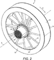
Figure 2 shows the rotor of the electrical machine ofFigure 1 ; -
Figure 3 shows a front view of the rotor ofFigure 2 , with certain parts removed for clarity; -
Figure 4 shows a cross section taken along line A-A ofFigure 3 ; and -
Figure 5 shows a cross section taken along line B-B ofFigure 3 . - With reference to
Figure 1 , anelectrical machine 2 comprises astator 4 and arotor 6. Thestator 6 is supported in ahousing 8. Thehousing 8 also mounts afront plate 10 and arear plate 12 which respectively mount front andrear bearings rotor 6. In an alternative configuration, abearing rotor 6. - The
stator 4 comprises a plurality of windings arranged on a core, as is known in the art and need not therefore be described further here. - The
rotor 6 comprises a radiallyinner rotor hub 22, a radiallyouter rotor rim 24 and a plurality ofspokes 26 extending between the radiallyinner hub 22 and the radiallyouter rim 24 for supporting the radiallyouter rim 24. In this embodiment, there are twelve equi-spacedspokes 26, but the number, spacing and physical dimensions of thespokes 26 may be chosen to provide the necessary mechanical strength to therotor 6. - In this embodiment, the
rotor hub 22,rotor rim 24 andspokes 26 are formed as a unitary one-piece component. In other embodiments, however, two or more of these components may be separately formed and suitably coupled together. - The radially
inner hub 22 is coupled to ashaft 28 supported by the front andrear bearings rotor 6. Therotor 6 rotates about the axis A in a rotational direction B. Theinner hub 22 may be an integral part of theshaft 28 or be a separate component mounted to theshaft 28. As can be seen inFigure 2 , theshaft 28 hasinternal splines 30 for driving attachment to a rotary output or input (depending on whether themachine 2 is being used as a motor or a generator). Alternative drive configurations are possible, for example a bolted drive plate, a hirth coupling, or other couplings. - The
rotor 6 further comprises afront wall 32 andarear plate 34 extending radially outwardly at the front and rear of therotor rim 24. - A
magnet 36, for example a permanent magnet, is supported on therotor rim 24 between the annular front andrear walls cover 38 radially retains themagnet 36 on therotor rim 24. - As can be seen most clearly from
Figures 2 ,3 and5 , thespokes 26 do not extend parallel to the axis of rotation A and axial direction of therotor 6, but are arranged at an acute angle α thereto. That is, thespokes 26 do not extend parallel to the axial direction. The effect of angling thespokes 26 in this manner is that as therotor 6 rotates, thespokes 26 will act as an impeller and draw air through therotor 6, thereby cooling therotor 6. - In this embodiment, the angle α is about 25°, however, the angle may be chosen to provide the desired aerodynamic performance and airflow and to facilitate manufacture. In some embodiments, the angle α may be between 10° and 40°. However, the angle could be greater than 0° and less than 90°, although there will be a loss of efficiency at the extremes of that range.
- In this embodiment, the
spokes 26 are angled at a constant angle α relative to the axial direction along their entire radial extent. However, in other embodiments, thespokes 26 may twist along their radial length such that the angle α varies along their length. - In this embodiment, the
spokes 26 extend radially at their leading edges 50. In other embodiments, however, thespokes 26 may lean in a circumferential direction relative to the radial direction. - In the illustrated embodiment, the
spokes 26 are substantially rectilinear in cross section, as can best be seen inFigure 5 . Thus thespokes 26 are constructed as flat vanes in this embodiment. However, in other embodiments, thespokes 26 may curve axially (illustrated schematically as spoke 26' inFigure 5 ). In other embodiments, the spokes may be curved so as to have an airfoil shape in cross section (illustrated schematically as spoke 26" inFigure 5 ). A curved or airfoil shape may potentially improve the airflow through therotor 6. However, the structural performance of therotor 6 may limit the shaping of thespokes 26. - In the case of a
planar spoke 26, the angle relative to the axial direction may be constant throughout the axial length of each spoke 26. In the case of a curved or airfoil shaped spoke 26', 26", however, this angle will vary along the axial length of thespoke 26', 26". - It will be understood that as the
rotor 6 rotates the angled arrangement of thespokes 26 will act to draw air through therotor 6, thereby cooling therotor 6. While the angling of thespokes 26 may be optimised for cooling airflow when therotor 6 is rotating in a particular design direction, some cooling airflow may still be provided when therotor 6 is rotating in the opposite direction. - It will be appreciated that the electrical machine as described above has a number of advantages. The
spokes 26 reduce the weight of therotor 6 and at the same time act to induce a cooling airflow through therotor 6. This avoids the need for a separate cooling fan to be coupled to therotor 6. This reduces the number of parts in themachine 2, thus reducing the weight and cost of themachine 2. It also potentially simplifies the assembly of themachine 2, its bearings and lubrication system. - The disclosure is of application to all rotary electrical machines. It will, however, find particular application in high performance machines such as electrical propulsion motors and generators.
Claims (15)
- A rotary electrical machine (2) comprising:a stator (4); anda rotor (6);wherein the rotor (6) comprises:a radially inner rotor hub (22) rotatable about an axis of rotation (A) which defines an axial direction of the rotor (6);a radially outer rotor rim (24) configured to support a magnet (36); anda plurality of spokes (26) extending between the rotor hub (22) and the rotor rim (24) for supporting the rotor rim (24);wherein the spokes (26) are arranged relative to the axial direction of the rotor (6) so as to induce a flow of air through the rotor (6) when the rotor (6) rotates about the axis of rotation (A).
- A rotor (6) for an electrical machine (2), the rotor (6) comprising:a radially inner rotor hub (22) rotatable about an axis of rotation (A) which defines an axial direction of the rotor (6);a radially outer rotor rim (24) supporting or configured to support a magnet (36); anda plurality of spokes (26) extending between the rotor hub (22) and the rotor rim (24) for supporting the rotor rim (24);wherein the spokes (26) are arranged relative to the axial direction of the rotor so as to induce a flow of air through the rotor (6) when the rotor (6) rotates about the axis (A).
- A rotary electric machine as claimed in claim 1 or rotor as claimed in claim 2, wherein the spokes (26) are arranged at an angle to the axial direction.
- A rotary electric machine or rotor as claimed in claim 3, wherein the spokes (26) are arranged at an angle of between 10° and 40° to the axial direction.
- A rotary electric machine or rotor as claimed in claim 4, wherein the spokes (26) are angled at an angle of 25° to the axial direction.
- A rotary electric machine or rotor as claimed in any of claims 2 to 6, wherein the spokes (26) are angled at a constant angle relative to the axial direction along their radial extent.
- A rotary electric machine or rotor as claimed in any of claims 2 to 7, wherein the spokes (26) are angled at a constant angle relative to the axial direction along their longitudinal extent.
- A rotary electric machine or rotor as claimed in any preceding claim, wherein the spokes (26) are rectilinear in cross section in the axial direction.
- A rotary electric machine or rotor as claimed in any of claims 1 to 7, wherein the spokes (26') are curved in cross section in the axial direction.
- A rotary electric machine or rotor as claimed in any of claims 1 to 7, wherein the spokes (26") are airfoil shaped in cross section in the axial direction.
- A rotary electric machine or rotor as claimed in any preceding claim, wherein the spokes (26; 26'; 26") extend radially at their leading edges.
- A rotary electric machine or rotor as claimed in any preceding claim, wherein the rotor hub (22), the rotor rim (24) and the spokes (26; 26'; 26"), are a unitary one piece component.
- A rotary electric machine or rotor as claimed in any preceding claim, wherein the rotor (6) further comprises an annular front wall (32) and an annular rear wall (34) extending radially outwardly from the rotor rim (24), a magnet (36) being retained axially between the annular front wall (32) and the annular rear wall (34).
- A method of manufacturing an electrical machine (2) comprising a stator (4) and a rotor (6), the rotor (6) comprising a radially inner rotor hub (22) rotating in use about an axis of rotation (A) defining an axial direction of the rotor (6), a radially outer rotor rim (24) supporting a magnet (36); and a plurality of spokes (26) extending between the rotor hub (24) and the rotor rim (24) for supporting the rotor rim (24), the method comprising arranging the spokes (26) relative to the axial direction of the rotor (6) so as to induce a flow of air through the rotor (6) when the rotor (6) rotates.
- A method of cooling an electric machine (2) comprising a stator (4) and a rotor (6), the method comprising inducing an airflow through the machine (2) by rotating the rotor (6), the rotor (6) comprising a radially inner rotor hub (22) rotating about an axis of rotation defining an axial direction of the rotor (6), a radially outer rotor rim (24) supporting a magnet (36) and a plurality of spokes (26) extending between the rotor hub (22) and the rotor rim (24) for supporting the rotor rim (24), the spokes (26) being arranged relative to the axial direction of the rotor (6) so as to induce the flow of air through the rotor (6) when the rotor (6) rotates.
Priority Applications (2)
| Application Number | Priority Date | Filing Date | Title |
|---|---|---|---|
| EP19178253.1A EP3748821A1 (en) | 2019-06-04 | 2019-06-04 | Electrical machines |
| US16/718,265 US20200389068A1 (en) | 2019-06-04 | 2019-12-18 | Electrical machines |
Applications Claiming Priority (1)
| Application Number | Priority Date | Filing Date | Title |
|---|---|---|---|
| EP19178253.1A EP3748821A1 (en) | 2019-06-04 | 2019-06-04 | Electrical machines |
Publications (1)
| Publication Number | Publication Date |
|---|---|
| EP3748821A1 true EP3748821A1 (en) | 2020-12-09 |
Family
ID=66770254
Family Applications (1)
| Application Number | Title | Priority Date | Filing Date |
|---|---|---|---|
| EP19178253.1A Withdrawn EP3748821A1 (en) | 2019-06-04 | 2019-06-04 | Electrical machines |
Country Status (2)
| Country | Link |
|---|---|
| US (1) | US20200389068A1 (en) |
| EP (1) | EP3748821A1 (en) |
Citations (6)
| Publication number | Priority date | Publication date | Assignee | Title |
|---|---|---|---|---|
| EP0140461A1 (en) * | 1983-08-04 | 1985-05-08 | Comair Rotron Inc | Simple brushless dc fan motor with reversing field |
| DE4107962A1 (en) * | 1990-03-23 | 1991-09-26 | Valeo Equip Electr Moteur | AC generator for automobile - has permanent magnet rotor with axial and radial cooling |
| DE4311242A1 (en) * | 1993-04-06 | 1994-10-13 | Daimler Benz Ag | Method for producing a rotor of an electrical machine |
| WO2015005776A1 (en) * | 2013-07-09 | 2015-01-15 | Eco-Logical Enterprises B.V. | Rotary device, for instance an air mover such as a fan, a propeller or a lifting rotor, a water turbine or a wind turbine |
| CN106357051A (en) * | 2016-11-28 | 2017-01-25 | 山东理工大学 | Wheel hub motor driving system with internal and external circulating airway cooling structure |
| DE102016202741A1 (en) * | 2016-02-23 | 2017-08-24 | Siemens Aktiengesellschaft | Rotor and electric machine |
-
2019
- 2019-06-04 EP EP19178253.1A patent/EP3748821A1/en not_active Withdrawn
- 2019-12-18 US US16/718,265 patent/US20200389068A1/en not_active Abandoned
Patent Citations (6)
| Publication number | Priority date | Publication date | Assignee | Title |
|---|---|---|---|---|
| EP0140461A1 (en) * | 1983-08-04 | 1985-05-08 | Comair Rotron Inc | Simple brushless dc fan motor with reversing field |
| DE4107962A1 (en) * | 1990-03-23 | 1991-09-26 | Valeo Equip Electr Moteur | AC generator for automobile - has permanent magnet rotor with axial and radial cooling |
| DE4311242A1 (en) * | 1993-04-06 | 1994-10-13 | Daimler Benz Ag | Method for producing a rotor of an electrical machine |
| WO2015005776A1 (en) * | 2013-07-09 | 2015-01-15 | Eco-Logical Enterprises B.V. | Rotary device, for instance an air mover such as a fan, a propeller or a lifting rotor, a water turbine or a wind turbine |
| DE102016202741A1 (en) * | 2016-02-23 | 2017-08-24 | Siemens Aktiengesellschaft | Rotor and electric machine |
| CN106357051A (en) * | 2016-11-28 | 2017-01-25 | 山东理工大学 | Wheel hub motor driving system with internal and external circulating airway cooling structure |
Also Published As
| Publication number | Publication date |
|---|---|
| US20200389068A1 (en) | 2020-12-10 |
Similar Documents
| Publication | Publication Date | Title |
|---|---|---|
| EP2280150B1 (en) | Gas turbine engine with integrated starter-generator | |
| US5755557A (en) | Axial flow fan | |
| WO2007141968A1 (en) | Electric supercharger | |
| CN211089408U (en) | Outer-rotating multistage parallel-serial permanent magnet coreless motor for unmanned aerial vehicle | |
| NO347974B1 (en) | Improved arrangement for pressurizing of fluid | |
| EP3047151A1 (en) | A motor-generator shaft with centrifugal fan blades | |
| CN110247488B (en) | Cooling of generator end windings | |
| EP4325028A1 (en) | Electric machine with combined rotor and cooling fan | |
| CN111628621B (en) | Brushless disk type double-rotor motor | |
| EP2295726A1 (en) | Gas turbine engine compressor with integrated starter/generator | |
| CN113014052B (en) | Fan driving assembly | |
| US20200389068A1 (en) | Electrical machines | |
| EP3508720A1 (en) | Wind turbine including a cooling circuit | |
| EP4345257A1 (en) | Electric machine with combined rotor and cooling fan | |
| US11661858B2 (en) | Turbine generator | |
| CN113014053B (en) | Fan driving assembly | |
| AU2014322794A1 (en) | An electric or hybrid vehicle using motor-generator having shaft with centrifugal fan blades for cooling | |
| CN108397400A (en) | Blowing plant | |
| CN111971879B (en) | Rotary electric machine for internal combustion engine and rotor thereof | |
| US11346369B2 (en) | Blower assembly and methods of assembling the same | |
| EP3474428B1 (en) | A system | |
| CN219993983U (en) | Fan system with integrated hub, thermal management system and vehicle | |
| US12407204B2 (en) | Electric machine having rotor with integrated fan | |
| US20230074332A1 (en) | Integrated electric motor and thermal management system | |
| US20220052567A1 (en) | Fan |
Legal Events
| Date | Code | Title | Description |
|---|---|---|---|
| PUAI | Public reference made under article 153(3) epc to a published international application that has entered the european phase |
Free format text: ORIGINAL CODE: 0009012 |
|
| STAA | Information on the status of an ep patent application or granted ep patent |
Free format text: STATUS: THE APPLICATION HAS BEEN PUBLISHED |
|
| AK | Designated contracting states |
Kind code of ref document: A1 Designated state(s): AL AT BE BG CH CY CZ DE DK EE ES FI FR GB GR HR HU IE IS IT LI LT LU LV MC MK MT NL NO PL PT RO RS SE SI SK SM TR |
|
| AX | Request for extension of the european patent |
Extension state: BA ME |
|
| STAA | Information on the status of an ep patent application or granted ep patent |
Free format text: STATUS: REQUEST FOR EXAMINATION WAS MADE |
|
| 17P | Request for examination filed |
Effective date: 20210609 |
|
| RBV | Designated contracting states (corrected) |
Designated state(s): AL AT BE BG CH CY CZ DE DK EE ES FI FR GB GR HR HU IE IS IT LI LT LU LV MC MK MT NL NO PL PT RO RS SE SI SK SM TR |
|
| STAA | Information on the status of an ep patent application or granted ep patent |
Free format text: STATUS: EXAMINATION IS IN PROGRESS |
|
| 17Q | First examination report despatched |
Effective date: 20220324 |
|
| STAA | Information on the status of an ep patent application or granted ep patent |
Free format text: STATUS: THE APPLICATION IS DEEMED TO BE WITHDRAWN |
|
| 18D | Application deemed to be withdrawn |
Effective date: 20220804 |