EP3748756A1 - Electrode assembly, secondary battery comprising same, method for manufacturing secondary battery, and battery pack - Google Patents
Electrode assembly, secondary battery comprising same, method for manufacturing secondary battery, and battery pack Download PDFInfo
- Publication number
- EP3748756A1 EP3748756A1 EP19910955.4A EP19910955A EP3748756A1 EP 3748756 A1 EP3748756 A1 EP 3748756A1 EP 19910955 A EP19910955 A EP 19910955A EP 3748756 A1 EP3748756 A1 EP 3748756A1
- Authority
- EP
- European Patent Office
- Prior art keywords
- electrode assembly
- radical unit
- unit
- electrode
- surface protection
- Prior art date
- Legal status (The legal status is an assumption and is not a legal conclusion. Google has not performed a legal analysis and makes no representation as to the accuracy of the status listed.)
- Pending
Links
Images





Classifications
-
- H—ELECTRICITY
- H01—ELECTRIC ELEMENTS
- H01M—PROCESSES OR MEANS, e.g. BATTERIES, FOR THE DIRECT CONVERSION OF CHEMICAL ENERGY INTO ELECTRICAL ENERGY
- H01M50/00—Constructional details or processes of manufacture of the non-active parts of electrochemical cells other than fuel cells, e.g. hybrid cells
- H01M50/40—Separators; Membranes; Diaphragms; Spacing elements inside cells
- H01M50/403—Manufacturing processes of separators, membranes or diaphragms
- H01M50/406—Moulding; Embossing; Cutting
-
- H—ELECTRICITY
- H01—ELECTRIC ELEMENTS
- H01M—PROCESSES OR MEANS, e.g. BATTERIES, FOR THE DIRECT CONVERSION OF CHEMICAL ENERGY INTO ELECTRICAL ENERGY
- H01M50/00—Constructional details or processes of manufacture of the non-active parts of electrochemical cells other than fuel cells, e.g. hybrid cells
- H01M50/40—Separators; Membranes; Diaphragms; Spacing elements inside cells
- H01M50/46—Separators, membranes or diaphragms characterised by their combination with electrodes
- H01M50/461—Separators, membranes or diaphragms characterised by their combination with electrodes with adhesive layers between electrodes and separators
-
- H—ELECTRICITY
- H01—ELECTRIC ELEMENTS
- H01M—PROCESSES OR MEANS, e.g. BATTERIES, FOR THE DIRECT CONVERSION OF CHEMICAL ENERGY INTO ELECTRICAL ENERGY
- H01M10/00—Secondary cells; Manufacture thereof
- H01M10/04—Construction or manufacture in general
- H01M10/0413—Large-sized flat cells or batteries for motive or stationary systems with plate-like electrodes
-
- H—ELECTRICITY
- H01—ELECTRIC ELEMENTS
- H01M—PROCESSES OR MEANS, e.g. BATTERIES, FOR THE DIRECT CONVERSION OF CHEMICAL ENERGY INTO ELECTRICAL ENERGY
- H01M10/00—Secondary cells; Manufacture thereof
- H01M10/04—Construction or manufacture in general
- H01M10/0436—Small-sized flat cells or batteries for portable equipment
-
- H—ELECTRICITY
- H01—ELECTRIC ELEMENTS
- H01M—PROCESSES OR MEANS, e.g. BATTERIES, FOR THE DIRECT CONVERSION OF CHEMICAL ENERGY INTO ELECTRICAL ENERGY
- H01M10/00—Secondary cells; Manufacture thereof
- H01M10/04—Construction or manufacture in general
- H01M10/0459—Cells or batteries with folded separator between plate-like electrodes
-
- H—ELECTRICITY
- H01—ELECTRIC ELEMENTS
- H01M—PROCESSES OR MEANS, e.g. BATTERIES, FOR THE DIRECT CONVERSION OF CHEMICAL ENERGY INTO ELECTRICAL ENERGY
- H01M10/00—Secondary cells; Manufacture thereof
- H01M10/04—Construction or manufacture in general
- H01M10/0463—Cells or batteries with horizontal or inclined electrodes
-
- H—ELECTRICITY
- H01—ELECTRIC ELEMENTS
- H01M—PROCESSES OR MEANS, e.g. BATTERIES, FOR THE DIRECT CONVERSION OF CHEMICAL ENERGY INTO ELECTRICAL ENERGY
- H01M10/00—Secondary cells; Manufacture thereof
- H01M10/04—Construction or manufacture in general
- H01M10/0468—Compression means for stacks of electrodes and separators
-
- H—ELECTRICITY
- H01—ELECTRIC ELEMENTS
- H01M—PROCESSES OR MEANS, e.g. BATTERIES, FOR THE DIRECT CONVERSION OF CHEMICAL ENERGY INTO ELECTRICAL ENERGY
- H01M10/00—Secondary cells; Manufacture thereof
- H01M10/04—Construction or manufacture in general
- H01M10/0472—Vertically superposed cells with vertically disposed plates
-
- H—ELECTRICITY
- H01—ELECTRIC ELEMENTS
- H01M—PROCESSES OR MEANS, e.g. BATTERIES, FOR THE DIRECT CONVERSION OF CHEMICAL ENERGY INTO ELECTRICAL ENERGY
- H01M10/00—Secondary cells; Manufacture thereof
- H01M10/04—Construction or manufacture in general
- H01M10/049—Processes for forming or storing electrodes in the battery container
-
- H—ELECTRICITY
- H01—ELECTRIC ELEMENTS
- H01M—PROCESSES OR MEANS, e.g. BATTERIES, FOR THE DIRECT CONVERSION OF CHEMICAL ENERGY INTO ELECTRICAL ENERGY
- H01M10/00—Secondary cells; Manufacture thereof
- H01M10/05—Accumulators with non-aqueous electrolyte
- H01M10/058—Construction or manufacture
- H01M10/0585—Construction or manufacture of accumulators having only flat construction elements, i.e. flat positive electrodes, flat negative electrodes and flat separators
-
- H—ELECTRICITY
- H01—ELECTRIC ELEMENTS
- H01M—PROCESSES OR MEANS, e.g. BATTERIES, FOR THE DIRECT CONVERSION OF CHEMICAL ENERGY INTO ELECTRICAL ENERGY
- H01M50/00—Constructional details or processes of manufacture of the non-active parts of electrochemical cells other than fuel cells, e.g. hybrid cells
- H01M50/40—Separators; Membranes; Diaphragms; Spacing elements inside cells
- H01M50/409—Separators, membranes or diaphragms characterised by the material
- H01M50/411—Organic material
- H01M50/414—Synthetic resins, e.g. thermoplastics or thermosetting resins
-
- H—ELECTRICITY
- H01—ELECTRIC ELEMENTS
- H01M—PROCESSES OR MEANS, e.g. BATTERIES, FOR THE DIRECT CONVERSION OF CHEMICAL ENERGY INTO ELECTRICAL ENERGY
- H01M50/00—Constructional details or processes of manufacture of the non-active parts of electrochemical cells other than fuel cells, e.g. hybrid cells
- H01M50/40—Separators; Membranes; Diaphragms; Spacing elements inside cells
- H01M50/463—Separators, membranes or diaphragms characterised by their shape
- H01M50/466—U-shaped, bag-shaped or folded
-
- H—ELECTRICITY
- H01—ELECTRIC ELEMENTS
- H01M—PROCESSES OR MEANS, e.g. BATTERIES, FOR THE DIRECT CONVERSION OF CHEMICAL ENERGY INTO ELECTRICAL ENERGY
- H01M50/00—Constructional details or processes of manufacture of the non-active parts of electrochemical cells other than fuel cells, e.g. hybrid cells
- H01M50/40—Separators; Membranes; Diaphragms; Spacing elements inside cells
- H01M50/471—Spacing elements inside cells other than separators, membranes or diaphragms; Manufacturing processes thereof
- H01M50/474—Spacing elements inside cells other than separators, membranes or diaphragms; Manufacturing processes thereof characterised by their position inside the cells
-
- Y—GENERAL TAGGING OF NEW TECHNOLOGICAL DEVELOPMENTS; GENERAL TAGGING OF CROSS-SECTIONAL TECHNOLOGIES SPANNING OVER SEVERAL SECTIONS OF THE IPC; TECHNICAL SUBJECTS COVERED BY FORMER USPC CROSS-REFERENCE ART COLLECTIONS [XRACs] AND DIGESTS
- Y02—TECHNOLOGIES OR APPLICATIONS FOR MITIGATION OR ADAPTATION AGAINST CLIMATE CHANGE
- Y02E—REDUCTION OF GREENHOUSE GAS [GHG] EMISSIONS, RELATED TO ENERGY GENERATION, TRANSMISSION OR DISTRIBUTION
- Y02E60/00—Enabling technologies; Technologies with a potential or indirect contribution to GHG emissions mitigation
- Y02E60/10—Energy storage using batteries
-
- Y—GENERAL TAGGING OF NEW TECHNOLOGICAL DEVELOPMENTS; GENERAL TAGGING OF CROSS-SECTIONAL TECHNOLOGIES SPANNING OVER SEVERAL SECTIONS OF THE IPC; TECHNICAL SUBJECTS COVERED BY FORMER USPC CROSS-REFERENCE ART COLLECTIONS [XRACs] AND DIGESTS
- Y02—TECHNOLOGIES OR APPLICATIONS FOR MITIGATION OR ADAPTATION AGAINST CLIMATE CHANGE
- Y02P—CLIMATE CHANGE MITIGATION TECHNOLOGIES IN THE PRODUCTION OR PROCESSING OF GOODS
- Y02P70/00—Climate change mitigation technologies in the production process for final industrial or consumer products
- Y02P70/50—Manufacturing or production processes characterised by the final manufactured product
Definitions
- the present invention relates to an electrode assembly, a secondary battery comprising the electrode assembly, a method for manufacturing the secondary battery, and a battery pack, and more particularly, to an electrode assembly having a structure for blocking introduction of foreign substances into side surfaces, a secondary battery comprising the electrode assembly, a method for manufacturing the secondary battery, and a battery pack.
- secondary batteries refer to chargeable and dischargeable batteries, unlike primary batteries that are not chargeable.
- the secondary batteries are being widely used in the high-tech electronic fields such as mobile phones, notebook computers, and camcorders.
- the secondary batteries may be variously classified according to a structure of the electrode assembly.
- the secondary batteries may be classified into a stacking type structure, a jelly-roll-type structure, or a stacking/folding type structure.
- the stacking type secondary battery comprises an electrode assembly and a pouch that accommodates the electrode assembly, and the electrode assembly has a structure in which an electrode and a separator are separately stacked. Also, a lamination process is performed on the electrode assembly having the stacked structure as described above to improve bonding force.
- An object of the present invention is to provide an electrode assembly in which introduction of foreign substances and electrode powder into side surfaces of the electrode assembly is blocked to prevent low voltage failure from occurring, thereby improving quality, a secondary battery comprising the electrode assembly, a method for manufacturing the secondary battery, and a battery pack.
- the side surface protection part may adhere to each of side surfaces of each of the separators provided in the radical unit.
- Adhesion between the side surface protection part and the side surface of the separator may be less than that between the electrode and the separator, which are provided in the radical unit.
- the radical unit and the auxiliary unit may adhere to each other with adhesion less than that between the electrode and the separator, which are provided in the radical unit, or are adjacent to each other without the adhesion.
- the separation sheet may be made of a synthetic resin material.
- the electrode assembly may further comprise a fixing tape attached to surround the radical unit and the auxiliary unit.
- the auxiliary unit may further comprise an electrode disposed at the uppermost end side of the separation sheet.
- a cutoff line may be formed on a boundary between the separation part and the side surface protection part.
- the side surface protection part may have an area greater than that of the side surface of the radical unit.
- a secondary battery comprises: an electrode assembly; and a battery case configured to accommodate the electrode assembly, wherein the electrode assembly comprises: a radical unit in which a plurality of electrodes and a plurality of separators are alternately stacked, the radical unit having a structure in which one electrode is stacked at the uppermost end; and an auxiliary unit provided with a separation sheet disposed at the uppermost end side of the radical unit, wherein the separation sheet comprises: a separation part disposed at the uppermost end side of the radical unit; and a side surface protection part connected to each of side surfaces of the separation part and folded to contact a side portion of the radical unit to cover the side surfaces of the radical unit.
- a method for manufacturing the secondary battery according to the second embodiment of the present invention comprises: (A) a step of alternately stacking a plurality of electrode and a plurality of separators to manufacture a radical unit, wherein one electrode is stacked at the uppermost end of the radical unit; (B) an auxiliary unit completion step of cutting a separation film to manufacture an auxiliary unit provided with a separation part having a size corresponding to each of the separators and a side surface protection part connected to each of both side surfaces of the separator to manufacture a separation sheet; (C) a step of locating the auxiliary unit at the uppermost end side of the radical unit and folding the side surface protection part with respect to the separation part and then locating the side surface protection part on each of side surfaces of the radical unit to manufacture an unfinished electrode assembly; (D) a step of pressing the uppermost end and the lowermost end of the unfinished electrode assembly at the same time to allow the auxiliary unit and the radical unit to adhere to each other; (E) a step of attaching a fixing tape to surround the
- a battery pack comprises: one or more secondary batteries; and a pack case configured to accommodate the one or more secondary batteries, wherein the secondary battery comprises: an electrode assembly; and a battery case configured to accommodate the electrode assembly, wherein the electrode assembly comprises: a radical unit in which a plurality of electrodes and a plurality of separators are alternately stacked, the radical unit having a structure in which one electrode is stacked at the uppermost end; and an auxiliary unit provided with a separation sheet disposed at the uppermost end side of the radical unit, wherein the separation sheet comprises: a separation part disposed at the uppermost end side of the radical unit; and a side surface protection part connected to each of side surfaces of the separation part and folded to contact a side portion of the radical unit to cover the side surfaces of the radical unit.
- An electrode assembly according to a fourth embodiment of the present invention further comprises an electrode disposed at the uppermost end of a separation sheet of an auxiliary unit.
- An electrode assembly comprises a separation sheet, wherein the separation sheet further comprises a bottom surface protection part connected to a lower end surface of the side surface protection part and folded t contact the lowermost end surface of the radical unit.
- a portion or the whole of the bottom surface protection part may adhere to the lowermost end surface of the radical unit.
- the separation sheet may further comprise a surface protection part connected to each of both side surfaces of the side surface protection part and folded to contact each of front and rear sides of the radical unit.
- An electrode assembly according to a sixth embodiment of the present invention comprises a side surface protection part, wherein the side surface protection part is cut from a separation part when the electrode assembly is accommodated in a battery case.
- the electrode assembly of the present invention may comprise the radical unit and the auxiliary unit.
- the auxiliary unit may comprise the separation sheet, and the separation sheet may comprise the separation part disposed at the uppermost end side of the radical unit and a side surface protection part covering the side portion of the radical unit.
- an electrode assembly 100 according to a first embodiment of the present invention comprises a radical unit 110 and an auxiliary unit 120.
- the radical unit has a structure, a plurality of electrodes 111 and a plurality of separators 112 are alternately stacked.
- the radical unit 110 has a structure in which the electrode is stacked at the uppermost end.
- the radical unit 110 the plurality of electrodes 111 and the plurality of separators 112 are alternately stacked in a vertical direction.
- the radical unit 110 has a structure in which the electrode 111 is stacked at the uppermost end, and the separator 112 is stacked at the lowermost end.
- the plurality of electrodes 111 comprise a first electrode and a second electrode.
- a four-layered structure in which the first electrode, the separator, the second electrode, and the separator are stacked is stacked once or repeatedly stacked.
- Each of the electrodes 111 comprises a collector and an electrode active material layer applied to both side surfaces of the collector.
- the first electrode may be a negative electrode
- the second electrode may be a positive electrode, and vice versa.
- the auxiliary unit 120 comprises a separation sheet 122 disposed at the uppermost end side of the radical unit 110.
- the separation sheet 122 blocks introduction of foreign substances into the side surfaces of the radical unit 110 to prevent the side surfaces of the radical unit 110 from being contaminated.
- the separation sheet 122 comprises a separation part 122a disposed at the uppermost end side of the radical unit 110 and a side surface protection part 122b connected to each of side surfaces of the separation part 122a and folded to contact a side portion of the radical unit 110, thereby covering the side portion of the radical unit 110. That is, in the separation sheet 122, the separation part 122a is disposed at the uppermost end side of the radical unit 110 to protect the electrode disposed at the uppermost end of the radical unit 110, and the side surface protection part 122b is connected to each of both side surfaces of the separation part 122a. The side surface protection part 122b is folded toward each of the side surfaces of the radical unit 110 to block exposition of the side surfaces of the radical unit 110 to the outside.
- the auxiliary unit 120 may prevent the foreign substances from being introduced into the side surfaces of the radical unit through the separation sheet 122, thereby preventing quality problems such as low voltage failures from occurring.
- the separation sheet 122 may be made of an inexpensive material because the separation sheet 122 has only to blocks only the introduction of the foreign substances into the side surfaces of the radical unit 110. That is, the separation sheet 122 may be made of a synthetic resin material, particularly, a polyethylene terephthalate (PET) material to improve easy of purchase.
- PET polyethylene terephthalate
- the separation part 122a and the side surface protection part 122b are integrally formed to realize easy of manufacture and prevent the separation part 122a and the side surface protection part 122b from being separated from each other by an external impact.
- the side surface protection part 122b may adhere to a side surface of the separator 112 provided in the radical unit 110 to stably protect the side surface of the radical unit 110 through the side surface protection part 122b.
- heat is applied to an outer surface (a right surface when viewed in FIG. 3 ) of the side surface protection part 122b in a state in which a back surface (a left surface when viewed in FIG. 3 ) of the side surface protection part 122b and the side surface of the separator 112 provided in the radical unit 110 are in close contact with each other.
- the separator 112 and the side surface protection part 122b may adhere while a coating layer having adhesion force is melted.
- the separator 112 and the side surface protection part 122b may adhere to each other by using an adhesive to improve the adhesion force.
- the adhesion force between the side surface protection part 122b and each of the side surfaces of the separator 112 may be less than that between the electrode 111 and the separator 112 in the radical unit 110. That is, when the adhesion force between the side surface protection part 122b and the side surface of the separator 112 is equal or greater than that between the electrode 111 and the separator 112 in the radical unit 110, the electrode 111 and the separator 112 may also be separated from each other when the side surface protection part 122b and the separator 112, which adhere to each other, are separated from each other, thereby causing product defects.
- the sides surface protection part 122b may be removed from the separation part 122a of the separation sheet 122 to improve electrolyte impregnation.
- the adhesion force between the side surface protection part 122b and the side surface of the separator 112 is equal to or greater than that between the electrode 111 and the separator 112 in the radical unit 110, the electrode 111 and the separator 112 may be also separated in the radical unit 110 to cause defects.
- the adhesion force between the side surface protection part 122b and the side surface of the separator 112 may be less than that between the electrode 111 and the separator 112 in the radical unit 110.
- the side surface protection part 122b may be removed from the side surface of the separator 112 without separating the electrode 111 and the separator 112 in the radical unit 110.
- the auxiliary unit 120 having the above-described configuration may allow a battery capacity to increases and also prevent the foreign substances from being introduced into the side surfaces.
- the radical unit 110 and the separation sheet 122 of the auxiliary unit 120 may adhere to each other with adhesion force less than that between the electrode 111 and the separator 112 in the radical unit 110 or be adjacent to each other without the adhesion force. That is, when the radical unit 110 and the separation sheet 122 of the auxiliary unit 120, which are repeatedly stacked, are separated from each other, the electrode and the separator, which are provided in the radical unit 110, may be separated from each other in the radical unit due to a difference in adhesion force.
- the adhesion force may be expressed as peeling force.
- the adhesion force between the electrode and the separator may be expressed as force required for separating the electrode and the separator from each other.
- the radical unit 110 and the separation sheet 122 of the auxiliary unit 120 may adhere to each other with adhesive force less than that between the electrode 111 and the separator 112 or be adjacent to each other without the adhesion force.
- the electrode and the separator, which are provided in the radical unit may be prevented from being separated from each other to previously prevent defects from occurring.
- a fixing tape attached to surround the radical unit 110 and the auxiliary unit 120 may be further provided.
- the fixing tape 130 is attached to be connected to the separation sheet 122 of the auxiliary unit 120 and a bottom surface of the separator 112 disposed at the lowermost end of the radical unit 110.
- bonding between the radical unit 110 and the auxiliary unit may be improved, and also, attachment of the side surface protection part 122b of the separation sheet 122 provided in the auxiliary unit 120 may be improved.
- the side surface protection part 122b may have an area greater than that of the side surface of the radical unit 110. Thus, even though a meandering defect occurs in the side surface protection part 122b, the side surface protection part 122b may stably cover the side surface of the radical unit 110.
- a fine punching hole through which the foreign substances do not passes, but an electrolyte passes, may be formed in the side surface protection part 122b of the separation sheet 122.
- the penetrability of the electrolyte into the side surface of the electrode assembly 100 in which the side surface protection part 122b of the separation sheet 122 is provided may be improved by the punching hole, and thus, the impregnation of the electrolyte into the side surface of the electrode assembly 100 may be improved.
- the electrode assembly 100 according to the first embodiment of the present invention comprises the auxiliary unit 120 provided with the separation sheet 122. Therefore, the introduction of the foreign substances into the side surface of the electrode assembly 100 may be prevented to previously prevent the defects from occurring.
- a secondary battery 10 according to a second embodiment of the present invention comprises an electrode assembly 100 and a case 200 accommodating the electrode assembly 100.
- the electrode assembly 100 comprises a radical unit 110 having a structure, in which a plurality of electrodes 111 and a plurality of separators 112 are alternately stacked, and one electrode is stacked at the uppermost end, and an auxiliary unit 120 provided with a separation sheet 122 disposed at the uppermost end side of the radical unit 110.
- the separation sheet 122 comprises a separation part 122a disposed at the uppermost end side of the radical unit 110 and a side surface protection part 122b connected to each of side surfaces of the separation part 122a and folded to contact a side portion of the radical unit 110, thereby covering side surfaces of the radical unit 110.
- the electrode assembly 100 has the same configuration and function as the above-described electrode assembly according to the first embodiment of the present invention, and thus, the same reference numerals are used, and duplicated descriptions are omitted.
- the secondary battery 10 comprises an electrode assembly 100 provided with a separation sheet 122.
- introduction of foreign substances into side surface of the electrode assembly 100 may be prevented to previously prevent defects from occurring, thereby improving commerciality.
- the separation sheet 122 may protect the side surfaces of the electrode assembly 100 to prevent the side surfaces of the electrode assembly 100 from being damaged.
- a method for manufacturing a secondary battery according to a second embodiment of the present invention comprises (A) a radical unit manufacturing step, (B) an auxiliary manufacturing step, (C) an unfinished electrode assembly manufacturing step, (D) an unfinished electrode assembly pressing step, (E) a finished electrode assembly manufacturing step, and (F) a secondary battery manufacturing step.
- a plurality of electrode 111 and a plurality of separators 112 are alternately stacked to manufacture a radical unit 110.
- the radical unit 110 has a structure in which one electrode 111 is stacked at the uppermost end, and one separator 112 is stacked at the lowermost end.
- the plurality of electrodes may be a negative electrode and a positive electrode.
- the radical unit manufacturing step has a structure in which a four-layered structure comprising the negative electrode that is one electrode, the separator 112, the positive electrode that is the other electrode, and the separator 112 is stacked once or repeatedly stacked.
- a separation film 122A having a predetermined size is cut to manufacture a separation sheet 122 comprising a separation part 122a having a size corresponding to the separator 112 and a side surface protection part 122b connected to each of both side surfaces of the separation part 122a. Accordingly, the auxiliary unit 120 provided with the separation sheet 122 may be manufactured.
- the separation part 122a of the auxiliary unit 120 are disposed at the uppermost end side of the radical unit 110.
- the side surface protection part 122b is disposed to contact a side surface of the radical unit 110 to manufacture an unfinished electrode assembly 100A.
- the unfinished electrode assembly pressing step the uppermost end and the lowermost end of the unfinished electrode assembly 100A are pressed using a pressing device 30 to bond the radical unit 110 and the auxiliary unit 120, which are provided in the unfinished electrode assembly 100A, to each other.
- the radical unit 110 and the auxiliary unit 120 adhere to each other with adhesion force less than that between the electrode 111 and the separator in the radical unit 110.
- the (D) unfinished electrode assembly pressing step further comprises a process of allowing the side surface protection part 122b and the side surface of the separator 112 to adhere to each other. That is, when the pressing of the unfinished electrode assembly 100A is completed, a left end and a right end of the unfinished electrode assembly 100A are pressed using the pressing device 30 to allow the side surface protection part 122b and the side surface of the separator 112, which are folded with respect to each other, to adhere to each other.
- adhesion force between the side surface protection part 122b and the side surface of the separator 112 is less than that between the electrode 111 and the separator 112 in the radical unit 110.
- a fixing tape 130 is attached to surround the unfinished electrode assembly, thereby manufacturing a finished electrode assembly 100. That is, in the finished electrode assembly manufacturing step, one end of the fixing tape 130 is attached to the separation part 122a of the separation sheet 122 of the auxiliary unit 120, and the other end of the fixing tape 120 is attached to a bottom surface of the separator 112 disposed at the lowermost end of the radical unit 110 via the side surface protection part 122b of the separation sheet 122.
- the fixing tape 130 is attached to both side surfaces of the unfinished electrode assembly.
- the finished electrode assembly 100 and an electrolyte (not shown) are accommodated in a case 200, and then, an edge surface of the case 200 is sealed to manufacture a finished secondary battery 10.
- a battery pack 1 according to a third embodiment of the present invention comprises one or more secondary batteries 10 and a pack case 20 accommodating the one or more secondary batteries 10.
- Each of the secondary batteries 10 comprises an electrode assembly 100 and a case 200 accommodating the electrode assembly 100.
- the electrode assembly 100 comprises a radical unit 110 having a structure, in which a plurality of electrodes 111 and a separators 112 are alternately stacked, and one electrode 111 is stacked at the uppermost end, and an auxiliary unit provided with a separation sheet 122 disposed at the uppermost end side of the radical unit 110.
- the separation sheet 122 comprises a separation part 122a disposed at the uppermost end side of the radical unit 110 and a side surface protection part 122b connected to a side surface of the separation part 122a and folded to contact a side portion of the radical unit 110 to cover the side portion of the radical unit 110.
- the secondary battery 10 has the same configuration and function as the above-described secondary battery according to the second embodiment of the present invention, and thus, the same reference numerals are used for the same configuration, and duplicated descriptions are omitted.
- the battery pack 1 according to the third embodiment of the present invention comprises the secondary battery 10 provided with the separation sheet to significantly reduce a defective rate.
- an electrode assembly 100 according to a fourth embodiment of the present invention comprises an auxiliary unit 120 provided with a separation sheet 122 disposed at the uppermost end side of the radical unit 110.
- the separation sheet 122 comprises a separation part 122a disposed at the uppermost end side of the radical unit 110 and a side surface protection part 122b connected to each of side surfaces of the separation part 122a and folded to contact a side portion of the radical unit 110, thereby covering the side portion of the radical unit 110.
- the separator sheet 122 is made of the same material as the separator 112 provided in the radical unit 110.
- the auxiliary unit 120 may further comprise an electrode 121 disposed at the uppermost end side of the separation sheet 122.
- the auxiliary unit 120 has a structure in which the electrode 121 and the separation sheet 122 are alternately stacked in a vertical direction.
- the auxiliary unit 120 in which the electrode 121 and the separation sheet 122 are stacked vertically is stacked on a top surface side of the electrode 111 disposed at the uppermost end side of the radical unit 110.
- the electrode 121 of the auxiliary unit 120 and the electrode 111 disposed at the uppermost end of the radical unit 110 have different polarities. That is, when the electrode 111 disposed at the uppermost end of the radical unit 110 is a first electrode, the electrode 121 of the auxiliary unit 120 may be a second electrode. On the other hand, when the electrode 111 disposed at the uppermost end of the radical unit 110 is a second electrode, the electrode 121 of the auxiliary unit 120 may be a first electrode.
- the separation sheet 122 comprises a separation part 122a disposed at the uppermost end side of the radical unit 110 and a side surface protection part 122b connected to each of side surfaces of the separation part 122a and folded to contact a side portion of the radical unit 110, thereby covering the side portion of the radical unit 110. That is, in the separation sheet 122, the separation part 122a is disposed at the uppermost end side of the radical unit 110 to separate the electrode 121 of the auxiliary unit 120 from the electrode 111 disposed at the uppermost end of the radical unit 110 and connect the side surface protection part 122b to each of both side surfaces of the separation part 122a.
- the side surface protection part 122b is folded toward the side surface of the radical unit 110 to prevent the side surface of the radical unit 110 from being exposed to the outside. radical unit 110 to block exposition of the side surfaces of the radical unit 110 to the outside.
- the electrode assembly 100 according to the fourth embodiment of the present invention may block the introduction of the foreign matter into the side surface and simultaneously secure a large battery capacity.
- the electrode 121 has a structure in which an electrode active material layer is provided only on one surface facing the separation sheet 122. That is, the electrode 121 comprises an electrode collector 121a and an electrode active material layer 121b applied to an inner surface (a bottom surface of the electrode collector when viewed in FIG. 9 ) of the electrode collector 121a, which faces the separation sheet 122.
- the electrode assembly 100 according to the fourth embodiment of the present invention may prevent the electrode active material layer from being unnecessarily wasted, thereby significantly reducing costs.
- an electrode assembly 100 comprises a radical unit 110 and an auxiliary unit 120.
- the auxiliary unit 120 comprises a separation sheet 122, and the separation sheet 122 is disposed at the uppermost end side of the radical unit 110.
- the separation sheet 122 comprises a separation part 122a disposed at the uppermost end side of the radical unit 110 and a side surface protection part 122b connected to each of side surfaces of the separation part 122a and folded to contact a side portion of the radical unit 110, thereby covering the side portion of the radical unit 110.
- the separation sheet 122 further comprises a bottom surface protection part 122c connected to a lower end surface of the side surface protection part 122b and folded to contact the lowermost end surface of the radical unit 110 to prevent foreign substances from being introduced between the lowermost end surface of the radical unit 110 and the side surface protection part 122b through the bottom surface protection part 122c.
- a portion or the whole of the bottom surface protection part 122c may adhere to the lowermost end surface of the radical unit 110.
- fixing force of the separation sheet 122 may increase to improve adhesion between the side surface protection part 122b and the separator 112 of the radical unit 110.
- the separation sheet 122 further comprises a surface protection part 122d connected to each of both side surfaces (front and rear surfaces of the side surface protection part when viewed in FIG. 10 ) of the side surface protection part 122b and folded to contact each of front and rear surfaces of the radical unit 110 to effectively prevent the foreign substances introduced into the front and rear surfaces of the radical unit 110 through the surface protection part 122d.
- the separation sheet 122 comprises the separation part 122a, the side surface protection part 122b provided on each of both side surfaces of the separation part 122a, the bottom surface protection part 122c provided on each of both side surfaces of the side surface protection part 122b, and the surface protection part 122d provided on each of the front and rear surfaces of the side surface protection part 122b.
- the electrode assembly 100 according to the fifth embodiment of the present invention may prevent the foreign substances from being introduced into the front and rear sides as well as the side surfaces of the electrode assembly.
- a separation sheet 122 comprises a separation part 122a and a side surface protection part 122b.
- the side surface protection part may be removed from the separation part 122a.
- side surfaces of the electrode 100 may be opened to improve impregnation of the electrode assembly 100 and the electrolyte when the secondary battery is manufactured.
- the side surfaces of the electrode assembly 100 may be protected through the side surface protection part 122b of the separation sheet 122, and when the electrode assembly 100 is completely manufactured, the side surface protection part 122b of the separation sheet 122 may be removed to open the side surfaces of the electrode assembly 100.
- a cutoff line 122a may be formed on a boundary between the separation part 122a and the side surface protection part 122b, and thus, the side surface protection part 122b may be easily cut along the cutoff line 122a.
Landscapes
- Chemical & Material Sciences (AREA)
- Chemical Kinetics & Catalysis (AREA)
- Electrochemistry (AREA)
- General Chemical & Material Sciences (AREA)
- Engineering & Computer Science (AREA)
- Manufacturing & Machinery (AREA)
- Secondary Cells (AREA)
- Cell Separators (AREA)
Abstract
Description
- The present application claims the benefit of the priority of Korean Patent Application No.
10-2019-0008258, filed on January 22, 2019 - The present invention relates to an electrode assembly, a secondary battery comprising the electrode assembly, a method for manufacturing the secondary battery, and a battery pack, and more particularly, to an electrode assembly having a structure for blocking introduction of foreign substances into side surfaces, a secondary battery comprising the electrode assembly, a method for manufacturing the secondary battery, and a battery pack.
- In general, secondary batteries refer to chargeable and dischargeable batteries, unlike primary batteries that are not chargeable. The secondary batteries are being widely used in the high-tech electronic fields such as mobile phones, notebook computers, and camcorders.
- The secondary batteries may be variously classified according to a structure of the electrode assembly. For example, the secondary batteries may be classified into a stacking type structure, a jelly-roll-type structure, or a stacking/folding type structure.
- The stacking type secondary battery comprises an electrode assembly and a pouch that accommodates the electrode assembly, and the electrode assembly has a structure in which an electrode and a separator are separately stacked. Also, a lamination process is performed on the electrode assembly having the stacked structure as described above to improve bonding force.
- However, in a transfer step of the lamination process, there is a problem that foreign substances such as electrode powder are introduced into side surfaces of the electrode assembly. As a result, quality problems such as low voltage failure may occur due to the foreign substances introduced into the side surfaces of the electrode assembly.
- An object of the present invention is to provide an electrode assembly in which introduction of foreign substances and electrode powder into side surfaces of the electrode assembly is blocked to prevent low voltage failure from occurring, thereby improving quality, a secondary battery comprising the electrode assembly, a method for manufacturing the secondary battery, and a battery pack.
- An electrode assembly according to a first embodiment of the present invention for achieving the above object comprises: a radical unit in which a plurality of electrodes and a plurality of separators are alternately stacked, the radical unit having a structure in which one electrode is stacked at the uppermost end; and an auxiliary unit provided with a separation sheet disposed at the uppermost end side of the radical unit, wherein the separation sheet comprises: a separation part disposed at the uppermost end side of the radical unit; and a side surface protection part connected to each of side surfaces of the separation part and folded to contact a side portion of the radical unit to cover the side portion of the radical unit.
- The side surface protection part may adhere to each of side surfaces of each of the separators provided in the radical unit.
- Adhesion between the side surface protection part and the side surface of the separator may be less than that between the electrode and the separator, which are provided in the radical unit.
- The radical unit and the auxiliary unit may adhere to each other with adhesion less than that between the electrode and the separator, which are provided in the radical unit, or are adjacent to each other without the adhesion.
- The separation sheet may be made of a synthetic resin material. The electrode assembly may further comprise a fixing tape attached to surround the radical unit and the auxiliary unit.
- The auxiliary unit may further comprise an electrode disposed at the uppermost end side of the separation sheet.
- A cutoff line may be formed on a boundary between the separation part and the side surface protection part.
- The side surface protection part may have an area greater than that of the side surface of the radical unit.
- A secondary battery according to a second embodiment of the present invention comprises: an electrode assembly; and a battery case configured to accommodate the electrode assembly, wherein the electrode assembly comprises: a radical unit in which a plurality of electrodes and a plurality of separators are alternately stacked, the radical unit having a structure in which one electrode is stacked at the uppermost end; and an auxiliary unit provided with a separation sheet disposed at the uppermost end side of the radical unit, wherein the separation sheet comprises:
a separation part disposed at the uppermost end side of the radical unit; and a side surface protection part connected to each of side surfaces of the separation part and folded to contact a side portion of the radical unit to cover the side surfaces of the radical unit. - A method for manufacturing the secondary battery according to the second embodiment of the present invention comprises: (A) a step of alternately stacking a plurality of electrode and a plurality of separators to manufacture a radical unit, wherein one electrode is stacked at the uppermost end of the radical unit; (B) an auxiliary unit completion step of cutting a separation film to manufacture an auxiliary unit provided with a separation part having a size corresponding to each of the separators and a side surface protection part connected to each of both side surfaces of the separator to manufacture a separation sheet; (C) a step of locating the auxiliary unit at the uppermost end side of the radical unit and folding the side surface protection part with respect to the separation part and then locating the side surface protection part on each of side surfaces of the radical unit to manufacture an unfinished electrode assembly; (D) a step of pressing the uppermost end and the lowermost end of the unfinished electrode assembly at the same time to allow the auxiliary unit and the radical unit to adhere to each other; (E) a step of attaching a fixing tape to surround the unfinished electrode assembly and thereby to manufacture a finished electrode assembly; and (F) a step of accommodating the finished electrode assembly in a battery case and sealing an edge surface of the battery case to manufacture a finished secondary battery.
- A battery pack according to a third embodiment of the present invention comprises: one or more secondary batteries; and a pack case configured to accommodate the one or more secondary batteries, wherein the secondary battery comprises: an electrode assembly; and a battery case configured to accommodate the electrode assembly, wherein the electrode assembly comprises: a radical unit in which a plurality of electrodes and a plurality of separators are alternately stacked, the radical unit having a structure in which one electrode is stacked at the uppermost end; and an auxiliary unit provided with a separation sheet disposed at the uppermost end side of the radical unit, wherein the separation sheet comprises: a separation part disposed at the uppermost end side of the radical unit; and a side surface protection part connected to each of side surfaces of the separation part and folded to contact a side portion of the radical unit to cover the side surfaces of the radical unit.
- An electrode assembly according to a fourth embodiment of the present invention further comprises an electrode disposed at the uppermost end of a separation sheet of an auxiliary unit.
- An electrode assembly according to a fifth embodiment of the present invention comprises a separation sheet, wherein the separation sheet further comprises a bottom surface protection part connected to a lower end surface of the side surface protection part and folded t contact the lowermost end surface of the radical unit.
- A portion or the whole of the bottom surface protection part may adhere to the lowermost end surface of the radical unit.
- The separation sheet may further comprise a surface protection part connected to each of both side surfaces of the side surface protection part and folded to contact each of front and rear sides of the radical unit.
- An electrode assembly according to a sixth embodiment of the present invention comprises a side surface protection part, wherein the side surface protection part is cut from a separation part when the electrode assembly is accommodated in a battery case.
- The electrode assembly of the present invention may comprise the radical unit and the auxiliary unit. The auxiliary unit may comprise the separation sheet, and the separation sheet may comprise the separation part disposed at the uppermost end side of the radical unit and a side surface protection part covering the side portion of the radical unit. Thus, the introduction of the foreign substances and the electrode powder into the side surfaces of the radical unit may be blocked to prevent the low voltage failure from occurring, thereby improving the quality.
-
-
FIG. 1 is a perspective view of an electrode assembly according to a first embodiment of the present invention. -
FIG. 2 is a side view of the electrode assembly according to the first embodiment of the present invention. -
FIG. 3 is an enlarged view of a portion 'A' illustrated inFIG. 2 . -
FIG. 4 is a side view of the electrode assembly to which a fixing tape is attached according to the first embodiment of the present invention. -
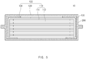
FIG. 5 is a cross-sectional view of a secondary battery according to a second embodiment of the present invention. -
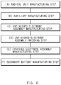
FIG. 6 is a flowchart illustrating a method for manufacturing the second battery according to the second embodiment of the present invention. -
FIG. 7 is a process view illustrating the method for manufacturing the second battery according to the second embodiment of the present invention. -
FIG. 8 is a schematic side view of a battery pack according to a third embodiment of the present invention. -
FIG. 9 is a cross-sectional view illustrating an auxiliary unit of an electrode assembly according to a fourth embodiment of the present invention. -
FIG. 10 is a perspective view of an electrode assembly according to a fifth embodiment of the present invention. -
FIG. 11 is a development view of a separation sheet ofFIG. 10 . -
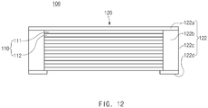
FIG. 12 is a front view ofFIG. 10 . -
FIG. 13 is a perspective view of an electrode assembly according to a sixth embodiment of the present invention. - Hereinafter, embodiments of the present invention will be described in detail with reference to the accompanying drawings in such a manner that the technical idea of the present invention may easily be carried out by a person with ordinary skill in the art to which the invention pertains. The present invention may, however, be embodied in different forms and should not be construed as limited to the embodiments set forth herein. In the drawings, anything unnecessary for describing the present invention will be omitted for clarity, and also like reference numerals in the drawings denote like elements.
- As illustrated in
FIGS. 1 to 3 , anelectrode assembly 100 according to a first embodiment of the present invention comprises aradical unit 110 and anauxiliary unit 120. - In the radical unit has a structure, a plurality of
electrodes 111 and a plurality ofseparators 112 are alternately stacked. Particularly, theradical unit 110 has a structure in which the electrode is stacked at the uppermost end. - That is, in the
radical unit 110, the plurality ofelectrodes 111 and the plurality ofseparators 112 are alternately stacked in a vertical direction. Thus, theradical unit 110 has a structure in which theelectrode 111 is stacked at the uppermost end, and theseparator 112 is stacked at the lowermost end. - Here, the plurality of
electrodes 111 comprise a first electrode and a second electrode. Thus, in theradical unit 110, a four-layered structure in which the first electrode, the separator, the second electrode, and the separator are stacked is stacked once or repeatedly stacked. - Each of the
electrodes 111 comprises a collector and an electrode active material layer applied to both side surfaces of the collector. - Also, the first electrode may be a negative electrode, and the second electrode may be a positive electrode, and vice versa.
- The
auxiliary unit 120 comprises aseparation sheet 122 disposed at the uppermost end side of theradical unit 110. Theseparation sheet 122 blocks introduction of foreign substances into the side surfaces of theradical unit 110 to prevent the side surfaces of theradical unit 110 from being contaminated. - For example, the
separation sheet 122 comprises aseparation part 122a disposed at the uppermost end side of theradical unit 110 and a sidesurface protection part 122b connected to each of side surfaces of theseparation part 122a and folded to contact a side portion of theradical unit 110, thereby covering the side portion of theradical unit 110. That is, in theseparation sheet 122, theseparation part 122a is disposed at the uppermost end side of theradical unit 110 to protect the electrode disposed at the uppermost end of theradical unit 110, and the sidesurface protection part 122b is connected to each of both side surfaces of theseparation part 122a. The sidesurface protection part 122b is folded toward each of the side surfaces of theradical unit 110 to block exposition of the side surfaces of theradical unit 110 to the outside. - Thus, the
auxiliary unit 120 may prevent the foreign substances from being introduced into the side surfaces of the radical unit through theseparation sheet 122, thereby preventing quality problems such as low voltage failures from occurring. - The
separation sheet 122 may be made of an inexpensive material because theseparation sheet 122 has only to blocks only the introduction of the foreign substances into the side surfaces of theradical unit 110. That is, theseparation sheet 122 may be made of a synthetic resin material, particularly, a polyethylene terephthalate (PET) material to improve easy of purchase. - Particularly, the
separation part 122a and the sidesurface protection part 122b are integrally formed to realize easy of manufacture and prevent theseparation part 122a and the sidesurface protection part 122b from being separated from each other by an external impact. - As illustrated in
FIG. 3 , the sidesurface protection part 122b may adhere to a side surface of theseparator 112 provided in theradical unit 110 to stably protect the side surface of theradical unit 110 through the sidesurface protection part 122b. - For example, heat is applied to an outer surface (a right surface when viewed in
FIG. 3 ) of the sidesurface protection part 122b in a state in which a back surface (a left surface when viewed inFIG. 3 ) of the sidesurface protection part 122b and the side surface of theseparator 112 provided in theradical unit 110 are in close contact with each other. As a result, theseparator 112 and the sidesurface protection part 122b may adhere while a coating layer having adhesion force is melted. Theseparator 112 and the sidesurface protection part 122b may adhere to each other by using an adhesive to improve the adhesion force. - The adhesion force between the side
surface protection part 122b and each of the side surfaces of theseparator 112 may be less than that between theelectrode 111 and theseparator 112 in theradical unit 110. That is, when the adhesion force between the sidesurface protection part 122b and the side surface of theseparator 112 is equal or greater than that between theelectrode 111 and theseparator 112 in theradical unit 110, theelectrode 111 and theseparator 112 may also be separated from each other when the sidesurface protection part 122b and theseparator 112, which adhere to each other, are separated from each other, thereby causing product defects. That is to say, when the finished electrode assembly is manufactured, the sidessurface protection part 122b may be removed from theseparation part 122a of theseparation sheet 122 to improve electrolyte impregnation. Here, when the adhesion force between the sidesurface protection part 122b and the side surface of theseparator 112 is equal to or greater than that between theelectrode 111 and theseparator 112 in theradical unit 110, theelectrode 111 and theseparator 112 may be also separated in theradical unit 110 to cause defects. - Thus, the adhesion force between the side
surface protection part 122b and the side surface of theseparator 112 may be less than that between theelectrode 111 and theseparator 112 in theradical unit 110. Thus, the sidesurface protection part 122b may be removed from the side surface of theseparator 112 without separating theelectrode 111 and theseparator 112 in theradical unit 110. - The
auxiliary unit 120 having the above-described configuration may allow a battery capacity to increases and also prevent the foreign substances from being introduced into the side surfaces. - The
radical unit 110 and theseparation sheet 122 of theauxiliary unit 120 may adhere to each other with adhesion force less than that between theelectrode 111 and theseparator 112 in theradical unit 110 or be adjacent to each other without the adhesion force. That is, when theradical unit 110 and theseparation sheet 122 of theauxiliary unit 120, which are repeatedly stacked, are separated from each other, the electrode and the separator, which are provided in theradical unit 110, may be separated from each other in the radical unit due to a difference in adhesion force. For reference, the adhesion force may be expressed as peeling force. For example, the adhesion force between the electrode and the separator may be expressed as force required for separating the electrode and the separator from each other. In order to prevent this phenomenon, theradical unit 110 and theseparation sheet 122 of theauxiliary unit 120 may adhere to each other with adhesive force less than that between theelectrode 111 and theseparator 112 or be adjacent to each other without the adhesion force. Thus, when theradical unit 110 and theseparation sheet 122 of theauxiliary unit 120 are separated from each other, the electrode and the separator, which are provided in the radical unit, may be prevented from being separated from each other to previously prevent defects from occurring. - A fixing tape attached to surround the
radical unit 110 and theauxiliary unit 120 may be further provided. - That is, as illustrated in
FIG. 4 , the fixingtape 130 is attached to be connected to theseparation sheet 122 of theauxiliary unit 120 and a bottom surface of theseparator 112 disposed at the lowermost end of theradical unit 110. As a result, bonding between theradical unit 110 and the auxiliary unit may be improved, and also, attachment of the sidesurface protection part 122b of theseparation sheet 122 provided in theauxiliary unit 120 may be improved. - The side
surface protection part 122b may have an area greater than that of the side surface of theradical unit 110. Thus, even though a meandering defect occurs in the sidesurface protection part 122b, the sidesurface protection part 122b may stably cover the side surface of theradical unit 110. - A fine punching hole through which the foreign substances do not passes, but an electrolyte passes, may be formed in the side
surface protection part 122b of theseparation sheet 122. The penetrability of the electrolyte into the side surface of theelectrode assembly 100 in which the sidesurface protection part 122b of theseparation sheet 122 is provided may be improved by the punching hole, and thus, the impregnation of the electrolyte into the side surface of theelectrode assembly 100 may be improved. - Thus, the
electrode assembly 100 according to the first embodiment of the present invention comprises theauxiliary unit 120 provided with theseparation sheet 122. Therefore, the introduction of the foreign substances into the side surface of theelectrode assembly 100 may be prevented to previously prevent the defects from occurring. - As illustrated in
FIG. 5 , asecondary battery 10 according to a second embodiment of the present invention comprises anelectrode assembly 100 and acase 200 accommodating theelectrode assembly 100. - Here, the
electrode assembly 100 comprises aradical unit 110 having a structure, in which a plurality ofelectrodes 111 and a plurality ofseparators 112 are alternately stacked, and one electrode is stacked at the uppermost end, and anauxiliary unit 120 provided with aseparation sheet 122 disposed at the uppermost end side of theradical unit 110. - Particularly, the
separation sheet 122 comprises aseparation part 122a disposed at the uppermost end side of theradical unit 110 and a sidesurface protection part 122b connected to each of side surfaces of theseparation part 122a and folded to contact a side portion of theradical unit 110, thereby covering side surfaces of theradical unit 110. - The
electrode assembly 100 has the same configuration and function as the above-described electrode assembly according to the first embodiment of the present invention, and thus, the same reference numerals are used, and duplicated descriptions are omitted. - Thus, the
secondary battery 10 according to the second embodiment of the present invention comprises anelectrode assembly 100 provided with aseparation sheet 122. Thus, introduction of foreign substances into side surface of theelectrode assembly 100 may be prevented to previously prevent defects from occurring, thereby improving commerciality. Particularly, theseparation sheet 122 may protect the side surfaces of theelectrode assembly 100 to prevent the side surfaces of theelectrode assembly 100 from being damaged. - As illustrated in
FIG. 6 , a method for manufacturing a secondary battery according to a second embodiment of the present invention comprises (A) a radical unit manufacturing step, (B) an auxiliary manufacturing step, (C) an unfinished electrode assembly manufacturing step, (D) an unfinished electrode assembly pressing step, (E) a finished electrode assembly manufacturing step, and (F) a secondary battery manufacturing step. - Referring to (a) of
FIG. 7 , in (A) the radical unit manufacturing step, a plurality ofelectrode 111 and a plurality ofseparators 112 are alternately stacked to manufacture aradical unit 110. Here, theradical unit 110 has a structure in which oneelectrode 111 is stacked at the uppermost end, and oneseparator 112 is stacked at the lowermost end. Here, the plurality of electrodes may be a negative electrode and a positive electrode. - That is, (A) the radical unit manufacturing step has a structure in which a four-layered structure comprising the negative electrode that is one electrode, the
separator 112, the positive electrode that is the other electrode, and theseparator 112 is stacked once or repeatedly stacked. - Referring to (b) of
FIG. 7 , in (B) the auxiliary unit manufacturing step, aseparation film 122A having a predetermined size is cut to manufacture aseparation sheet 122 comprising aseparation part 122a having a size corresponding to theseparator 112 and a sidesurface protection part 122b connected to each of both side surfaces of theseparation part 122a. Accordingly, theauxiliary unit 120 provided with theseparation sheet 122 may be manufactured. - Referring to (d) and (c) of
FIG. 7 , in (C) the unfinished electrode assembly manufacturing step, theseparation part 122a of theauxiliary unit 120 are disposed at the uppermost end side of theradical unit 110. Next, after being folded along a boundary between theseparation part 122a and the sidesurface protection part 122b, the sidesurface protection part 122b is disposed to contact a side surface of theradical unit 110 to manufacture anunfinished electrode assembly 100A. - Referring to (e) of
FIG. 7 , in (D) the unfinished electrode assembly pressing step, the uppermost end and the lowermost end of theunfinished electrode assembly 100A are pressed using apressing device 30 to bond theradical unit 110 and theauxiliary unit 120, which are provided in theunfinished electrode assembly 100A, to each other. - Here, the
radical unit 110 and theauxiliary unit 120 adhere to each other with adhesion force less than that between theelectrode 111 and the separator in theradical unit 110. - Referring to (f) of
FIG. 7 , the (D) unfinished electrode assembly pressing step further comprises a process of allowing the sidesurface protection part 122b and the side surface of theseparator 112 to adhere to each other. That is, when the pressing of theunfinished electrode assembly 100A is completed, a left end and a right end of theunfinished electrode assembly 100A are pressed using thepressing device 30 to allow the sidesurface protection part 122b and the side surface of theseparator 112, which are folded with respect to each other, to adhere to each other. - Here, adhesion force between the side
surface protection part 122b and the side surface of theseparator 112 is less than that between theelectrode 111 and theseparator 112 in theradical unit 110. - Referring to (g) of
FIG. 7 , in the finished electrode assembly manufacturing step, a fixingtape 130 is attached to surround the unfinished electrode assembly, thereby manufacturing afinished electrode assembly 100. That is, in the finished electrode assembly manufacturing step, one end of the fixingtape 130 is attached to theseparation part 122a of theseparation sheet 122 of theauxiliary unit 120, and the other end of the fixingtape 120 is attached to a bottom surface of theseparator 112 disposed at the lowermost end of theradical unit 110 via the sidesurface protection part 122b of theseparation sheet 122. Here, the fixingtape 130 is attached to both side surfaces of the unfinished electrode assembly. - Referring to (h) of
FIG. 7 , in (F) the secondary battery manufacturing step, thefinished electrode assembly 100 and an electrolyte (not shown) are accommodated in acase 200, and then, an edge surface of thecase 200 is sealed to manufacture a finishedsecondary battery 10. - As illustrated in
FIG. 8 , a battery pack 1 according to a third embodiment of the present invention comprises one or moresecondary batteries 10 and apack case 20 accommodating the one or moresecondary batteries 10. Each of thesecondary batteries 10 comprises anelectrode assembly 100 and acase 200 accommodating theelectrode assembly 100. - Also, the
electrode assembly 100 comprises aradical unit 110 having a structure, in which a plurality ofelectrodes 111 and aseparators 112 are alternately stacked, and oneelectrode 111 is stacked at the uppermost end, and an auxiliary unit provided with aseparation sheet 122 disposed at the uppermost end side of theradical unit 110. Theseparation sheet 122 comprises aseparation part 122a disposed at the uppermost end side of theradical unit 110 and a sidesurface protection part 122b connected to a side surface of theseparation part 122a and folded to contact a side portion of theradical unit 110 to cover the side portion of theradical unit 110. - The
secondary battery 10 has the same configuration and function as the above-described secondary battery according to the second embodiment of the present invention, and thus, the same reference numerals are used for the same configuration, and duplicated descriptions are omitted. - Thus, the battery pack 1 according to the third embodiment of the present invention comprises the
secondary battery 10 provided with the separation sheet to significantly reduce a defective rate. - As illustrated in
FIG. 9 , anelectrode assembly 100 according to a fourth embodiment of the present invention comprises anauxiliary unit 120 provided with aseparation sheet 122 disposed at the uppermost end side of theradical unit 110. - Here, the
separation sheet 122 comprises aseparation part 122a disposed at the uppermost end side of theradical unit 110 and a sidesurface protection part 122b connected to each of side surfaces of theseparation part 122a and folded to contact a side portion of theradical unit 110, thereby covering the side portion of theradical unit 110. - Particularly, the
separator sheet 122 is made of the same material as theseparator 112 provided in theradical unit 110. - The
auxiliary unit 120 may further comprise anelectrode 121 disposed at the uppermost end side of theseparation sheet 122. - That is, the
auxiliary unit 120 has a structure in which theelectrode 121 and theseparation sheet 122 are alternately stacked in a vertical direction. Theauxiliary unit 120 in which theelectrode 121 and theseparation sheet 122 are stacked vertically is stacked on a top surface side of theelectrode 111 disposed at the uppermost end side of theradical unit 110. - Here, the
electrode 121 of theauxiliary unit 120 and theelectrode 111 disposed at the uppermost end of theradical unit 110 have different polarities. That is, when theelectrode 111 disposed at the uppermost end of theradical unit 110 is a first electrode, theelectrode 121 of theauxiliary unit 120 may be a second electrode. On the other hand, when theelectrode 111 disposed at the uppermost end of theradical unit 110 is a second electrode, theelectrode 121 of theauxiliary unit 120 may be a first electrode. - For example, the
separation sheet 122 comprises aseparation part 122a disposed at the uppermost end side of theradical unit 110 and a sidesurface protection part 122b connected to each of side surfaces of theseparation part 122a and folded to contact a side portion of theradical unit 110, thereby covering the side portion of theradical unit 110. That is, in theseparation sheet 122, theseparation part 122a is disposed at the uppermost end side of theradical unit 110 to separate theelectrode 121 of theauxiliary unit 120 from theelectrode 111 disposed at the uppermost end of theradical unit 110 and connect the sidesurface protection part 122b to each of both side surfaces of theseparation part 122a. Here, the sidesurface protection part 122b is folded toward the side surface of theradical unit 110 to prevent the side surface of theradical unit 110 from being exposed to the outside.radical unit 110 to block exposition of the side surfaces of theradical unit 110 to the outside. - Thus, the
electrode assembly 100 according to the fourth embodiment of the present invention may block the introduction of the foreign matter into the side surface and simultaneously secure a large battery capacity. - The
electrode 121 has a structure in which an electrode active material layer is provided only on one surface facing theseparation sheet 122. That is, theelectrode 121 comprises anelectrode collector 121a and an electrodeactive material layer 121b applied to an inner surface (a bottom surface of the electrode collector when viewed inFIG. 9 ) of theelectrode collector 121a, which faces theseparation sheet 122. - Therefore, the
electrode assembly 100 according to the fourth embodiment of the present invention may prevent the electrode active material layer from being unnecessarily wasted, thereby significantly reducing costs. - As illustrated in
FIG. 10 to 12 , anelectrode assembly 100 according to a fifth embodiment of the present invention comprises aradical unit 110 and anauxiliary unit 120. Theauxiliary unit 120 comprises aseparation sheet 122, and theseparation sheet 122 is disposed at the uppermost end side of theradical unit 110. - For example, the
separation sheet 122 comprises aseparation part 122a disposed at the uppermost end side of theradical unit 110 and a sidesurface protection part 122b connected to each of side surfaces of theseparation part 122a and folded to contact a side portion of theradical unit 110, thereby covering the side portion of theradical unit 110. - The
separation sheet 122 further comprises a bottomsurface protection part 122c connected to a lower end surface of the sidesurface protection part 122b and folded to contact the lowermost end surface of theradical unit 110 to prevent foreign substances from being introduced between the lowermost end surface of theradical unit 110 and the sidesurface protection part 122b through the bottomsurface protection part 122c. - Particularly, a portion or the whole of the bottom
surface protection part 122c may adhere to the lowermost end surface of theradical unit 110. Thus, fixing force of theseparation sheet 122 may increase to improve adhesion between the sidesurface protection part 122b and theseparator 112 of theradical unit 110. - The
separation sheet 122 further comprises asurface protection part 122d connected to each of both side surfaces (front and rear surfaces of the side surface protection part when viewed inFIG. 10 ) of the sidesurface protection part 122b and folded to contact each of front and rear surfaces of theradical unit 110 to effectively prevent the foreign substances introduced into the front and rear surfaces of theradical unit 110 through thesurface protection part 122d. - In summary, referring to
FIG. 11 , theseparation sheet 122 comprises theseparation part 122a, the sidesurface protection part 122b provided on each of both side surfaces of theseparation part 122a, the bottomsurface protection part 122c provided on each of both side surfaces of the sidesurface protection part 122b, and thesurface protection part 122d provided on each of the front and rear surfaces of the sidesurface protection part 122b. - Therefore, the
electrode assembly 100 according to the fifth embodiment of the present invention may prevent the foreign substances from being introduced into the front and rear sides as well as the side surfaces of the electrode assembly. - As illustrated in
FIG. 13 , in anelectrode assembly 100 according to a sixth embodiment of the present invention, aseparation sheet 122 comprises aseparation part 122a and a sidesurface protection part 122b. When the electrode assembly is completely manufactured, the side surface protection part may be removed from theseparation part 122a. As a result, side surfaces of theelectrode 100 may be opened to improve impregnation of theelectrode assembly 100 and the electrolyte when the secondary battery is manufactured. - That is, since a large amount of foreign substances are generated when the electrode assembly is manufactured, the side surfaces of the
electrode assembly 100 may be protected through the sidesurface protection part 122b of theseparation sheet 122, and when theelectrode assembly 100 is completely manufactured, the sidesurface protection part 122b of theseparation sheet 122 may be removed to open the side surfaces of theelectrode assembly 100. - As illustrated in
FIG. 13 , acutoff line 122a may be formed on a boundary between theseparation part 122a and the sidesurface protection part 122b, and thus, the sidesurface protection part 122b may be easily cut along thecutoff line 122a. - Accordingly, the scope of the present invention is defined by the appended claims more than the foregoing description and the exemplary embodiments described therein. Various modifications made within the meaning of an equivalent of the claims of the invention and within the claims are to be regarded to be in the scope of the present invention.
Claims (14)
- An electrode assembly comprising:a radical unit in which a plurality of electrodes and a plurality of separators are alternately stacked, the radical unit having a structure in which one electrode is stacked at the uppermost end; andan auxiliary unit provided with a separation sheet disposed at the uppermost end side of the radical unit,wherein the separation sheet comprises:a separation part disposed at the uppermost end side of the radical unit; anda side surface protection part connected to each of side surfaces of the separation part and folded to contact a side portion of the radical unit to cover the side portion of the radical unit.
- The electrode assembly of claim 1, wherein the side surface protection part adheres to each of side surfaces of each of the separators provided in the radical unit.
- The electrode assembly of claim 2, wherein adhesion between the side surface protection part and the side surface of the separator is less than that between the electrode and the separator, which are provided in the radical unit.
- The electrode assembly of claim 2, wherein the radical unit and the auxiliary unit adheres to each other with adhesion less than that between the electrode and the separator, which are provided in the radical unit, or are adjacent to each other without the adhesion.
- The electrode assembly of claim 1, wherein the separation sheet further comprises a bottom surface protection part connected to a lower end surface of the side surface protection part and folded t contact the lowermost end surface of the radical unit.
- The electrode assembly of claim 5, wherein a portion or the whole of the bottom surface protection part adheres to the lowermost end surface of the radical unit.
- The electrode assembly of claim 1, wherein the separation sheet further comprises a surface protection part connected to each of both side surfaces of the side surface protection part and folded to contact each of front and rear sides of the radical unit.
- The electrode assembly of claim 1, wherein the separation sheet is made of a synthetic resin material.
- The electrode assembly of claim 1, further comprising a fixing tape attached to surround the radical unit and the auxiliary unit.
- The electrode assembly of claim 1, wherein the auxiliary unit further comprises an electrode disposed at the uppermost end side of the separation sheet.
- The electrode assembly of claim 1, wherein a cutoff line is formed on a boundary between the separation part and the side surface protection part.
- A secondary battery comprising:an electrode assembly; anda battery case configured to accommodate the electrode assembly,wherein the electrode assembly comprises:a radical unit in which a plurality of electrodes and a plurality of separators are alternately stacked, the radical unit having a structure in which one electrode is stacked at the uppermost end; andan auxiliary unit provided with a separation sheet disposed at the uppermost end side of the radical unit,wherein the separation sheet comprises:a separation part disposed at the uppermost end side of the radical unit; anda side surface protection part connected to each of side surfaces of the separation part and folded to contact a side portion of the radical unit to cover the side surfaces of the radical unit.
- The secondary battery of claim 12, wherein the side surface protection part is cut from the separation part when the electrode assembly is accommodated in the battery case.
- A method for manufacturing a secondary battery, the method comprising:(A) a step of alternately stacking a plurality of electrode and a plurality of separators to manufacture a radical unit, wherein one electrode is stacked at the uppermost end of the radical unit;(B) an auxiliary unit completion step of cutting a separation film to manufacture an auxiliary unit provided with a separation part having a size corresponding to each of the separators and a side surface protection part connected to each of both side surfaces of the separator to manufacture a separation sheet;(C) a step of locating the separation sheet of the auxiliary unit at the uppermost end side of the radical unit and folding the side surface protection part with respect to the separation part and then locating the side surface protection part on each of side surfaces of the radical unit to manufacture an unfinished electrode assembly;(D) a step of pressing the uppermost end and the lowermost end of the unfinished electrode assembly at the same time to allow the auxiliary unit and the radical unit to adhere to each other;(E) a step of attaching a fixing tape to surround the unfinished electrode assembly and thereby to manufacture a finished electrode assembly; and(F) a step of accommodating the finished electrode assembly in a battery case and sealing an edge surface of the battery case to manufacture a finished secondary battery.
Applications Claiming Priority (2)
| Application Number | Priority Date | Filing Date | Title |
|---|---|---|---|
| KR1020190008258A KR102316340B1 (en) | 2019-01-22 | 2019-01-22 | Electrode Assembly, Secondary battery with the Same and Method of thereof and Battery Pack |
| PCT/KR2019/016476 WO2020153594A1 (en) | 2019-01-22 | 2019-11-27 | Electrode assembly, secondary battery comprising same, method for manufacturing secondary battery, and battery pack |
Publications (2)
| Publication Number | Publication Date |
|---|---|
| EP3748756A1 true EP3748756A1 (en) | 2020-12-09 |
| EP3748756A4 EP3748756A4 (en) | 2021-05-26 |
Family
ID=71735781
Family Applications (1)
| Application Number | Title | Priority Date | Filing Date |
|---|---|---|---|
| EP19910955.4A Pending EP3748756A4 (en) | 2019-01-22 | 2019-11-27 | Electrode assembly, secondary battery comprising same, method for manufacturing secondary battery, and battery pack |
Country Status (5)
| Country | Link |
|---|---|
| US (1) | US11967734B2 (en) |
| EP (1) | EP3748756A4 (en) |
| KR (1) | KR102316340B1 (en) |
| CN (1) | CN111837284B (en) |
| WO (1) | WO2020153594A1 (en) |
Families Citing this family (2)
| Publication number | Priority date | Publication date | Assignee | Title |
|---|---|---|---|---|
| JPWO2023203795A1 (en) * | 2022-04-20 | 2023-10-26 | ||
| KR20240175393A (en) | 2023-06-13 | 2024-12-20 | 주식회사 엘지에너지솔루션 | Electrode assembly, secondary battery including the same, battery pack and vehicle |
Family Cites Families (23)
| Publication number | Priority date | Publication date | Assignee | Title |
|---|---|---|---|---|
| CN1236517C (en) * | 2000-02-29 | 2006-01-11 | 皇家菲利浦电子有限公司 | Lithium battery |
| JP2002324571A (en) | 2001-04-26 | 2002-11-08 | Matsushita Electric Ind Co Ltd | Battery plate group |
| JP4543710B2 (en) | 2004-03-11 | 2010-09-15 | 日産自動車株式会社 | Assembled battery |
| KR100853619B1 (en) | 2006-01-04 | 2008-08-25 | 주식회사 엘지화학 | Electrode assembly is sealed the top of the separator and a secondary battery comprising the same |
| JP4470124B2 (en) * | 2008-06-13 | 2010-06-02 | トヨタ自動車株式会社 | battery |
| KR101266617B1 (en) * | 2009-03-31 | 2013-05-22 | 미츠비시 쥬고교 가부시키가이샤 | Secondary battery and battery system |
| JP5757730B2 (en) | 2010-12-28 | 2015-07-29 | オートモーティブエナジーサプライ株式会社 | Film-clad battery, battery module, module assembly, method for producing film-clad battery, and electric vehicle |
| JP5844052B2 (en) * | 2011-02-04 | 2016-01-13 | 三洋電機株式会社 | Multilayer battery and method for manufacturing the same |
| US9859532B2 (en) * | 2011-03-31 | 2018-01-02 | Johnson Controls Technology Llc | Battery module and method incorporating exterior casing and liner |
| WO2014003481A1 (en) * | 2012-06-28 | 2014-01-03 | 주식회사 엘지화학 | Electrode assembly and electrochemical device containing same |
| JP5906970B2 (en) * | 2012-07-02 | 2016-04-20 | 株式会社豊田自動織機 | Power storage device |
| CN103564899A (en) | 2012-08-07 | 2014-02-12 | 香港理工大学 | Smart Adjustable Manikin |
| US10090553B2 (en) * | 2013-02-15 | 2018-10-02 | Lg Chem, Ltd. | Electrode assembly and method of manufacturing the same |
| KR101595643B1 (en) * | 2013-02-15 | 2016-02-18 | 주식회사 엘지화학 | Electrode assembly and cell of polymer lithium secondary battery comprising the same |
| KR101598666B1 (en) * | 2013-09-30 | 2016-03-02 | 주식회사 엘지화학 | Method of fixing electrode assembly using tape |
| KR101624386B1 (en) * | 2013-09-30 | 2016-05-25 | 주식회사 엘지화학 | Method of fixing electrode assembly using tape |
| KR101817399B1 (en) * | 2015-04-10 | 2018-01-11 | 주식회사 엘지화학 | Electrode assembly |
| KR101980308B1 (en) | 2015-05-27 | 2019-05-20 | 주식회사 엘지화학 | Secondary battery |
| KR101950448B1 (en) * | 2015-07-10 | 2019-02-20 | 주식회사 엘지화학 | The electrode assembly and manufacturing method of thereof |
| JP6610354B2 (en) | 2016-03-11 | 2019-11-27 | 株式会社豊田自動織機 | Electrode assembly and method for manufacturing electrode assembly |
| KR101963313B1 (en) | 2016-05-02 | 2019-03-28 | 주식회사 엘지화학 | Manufacturing method of secondary battery and manufacturing method of electrode assembly |
| KR20170138636A (en) | 2016-06-08 | 2017-12-18 | 주식회사 엘지화학 | Method for Electrode Assembly of Irregular Structure and Electrode Assembly Having Irregular Structure |
| KR102302054B1 (en) | 2016-09-29 | 2021-09-13 | 삼성에스디아이 주식회사 | Electrode assembly and rechargeable battery including the same |
-
2019
- 2019-01-22 KR KR1020190008258A patent/KR102316340B1/en active Active
- 2019-11-27 US US16/978,492 patent/US11967734B2/en active Active
- 2019-11-27 CN CN201980017982.6A patent/CN111837284B/en active Active
- 2019-11-27 WO PCT/KR2019/016476 patent/WO2020153594A1/en not_active Ceased
- 2019-11-27 EP EP19910955.4A patent/EP3748756A4/en active Pending
Also Published As
| Publication number | Publication date |
|---|---|
| KR20200091232A (en) | 2020-07-30 |
| CN111837284B (en) | 2024-02-09 |
| WO2020153594A1 (en) | 2020-07-30 |
| KR102316340B1 (en) | 2021-10-22 |
| CN111837284A (en) | 2020-10-27 |
| EP3748756A4 (en) | 2021-05-26 |
| US20210013475A1 (en) | 2021-01-14 |
| US11967734B2 (en) | 2024-04-23 |
Similar Documents
| Publication | Publication Date | Title |
|---|---|---|
| US11557810B2 (en) | Battery cell having main gas discharge tube and method for manufacturing the same | |
| US20240379990A1 (en) | Method for Manufacturing Secondary Battery and Pouch for Secondary Battery | |
| EP3321991B1 (en) | Pouch casing material for secondary battery | |
| EP2492989B1 (en) | Pouch type battery and method of manufacturing the same | |
| KR101927456B1 (en) | Secondary battery and manufacturing method thereof | |
| KR102401809B1 (en) | Method for manufacturing an electrode unit for a battery cell, and an electrode unit | |
| US20210143503A1 (en) | Pouch Case and the Method of Manufacturing the Pouch Type Secondary Battery Including the Same | |
| KR20170132565A (en) | Manufacturin method of rechargeable battery | |
| CN105322133A (en) | Secondary battery | |
| EP3748756A1 (en) | Electrode assembly, secondary battery comprising same, method for manufacturing secondary battery, and battery pack | |
| KR101264430B1 (en) | Pouch for secondary battery | |
| KR101825007B1 (en) | Pouch type secondary battery and method of fabricating the same | |
| EP4148886B1 (en) | Secondary battery and method for manufacturing the same | |
| CN112952241A (en) | Battery pack and label sheet therefor | |
| EP4304000A1 (en) | Electrode tab protective tape and secondary battery comprising same | |
| JP2006313655A (en) | Thin battery | |
| US20230198083A1 (en) | Secondary Battery | |
| EP3065194A1 (en) | Covering material-provided non-aqueous secondary cell, producing method thereof, and cell stack | |
| KR101792578B1 (en) | Battery Cell Having modified Lead Film | |
| CN115425364A (en) | Diaphragm piece, battery cell and method for manufacturing battery cell | |
| KR20180008039A (en) | Electrode assembly | |
| US20250239696A1 (en) | Battery pack | |
| EP4343904A1 (en) | Electrode assembly and secondary battery comprising same | |
| CN104851991B (en) | Battery and manufacturing method thereof | |
| EP4651275A1 (en) | Battery cell and battery module including same |
Legal Events
| Date | Code | Title | Description |
|---|---|---|---|
| STAA | Information on the status of an ep patent application or granted ep patent |
Free format text: STATUS: THE INTERNATIONAL PUBLICATION HAS BEEN MADE |
|
| PUAI | Public reference made under article 153(3) epc to a published international application that has entered the european phase |
Free format text: ORIGINAL CODE: 0009012 |
|
| STAA | Information on the status of an ep patent application or granted ep patent |
Free format text: STATUS: REQUEST FOR EXAMINATION WAS MADE |
|
| 17P | Request for examination filed |
Effective date: 20200901 |
|
| AK | Designated contracting states |
Kind code of ref document: A1 Designated state(s): AL AT BE BG CH CY CZ DE DK EE ES FI FR GB GR HR HU IE IS IT LI LT LU LV MC MK MT NL NO PL PT RO RS SE SI SK SM TR |
|
| AX | Request for extension of the european patent |
Extension state: BA ME |
|
| A4 | Supplementary search report drawn up and despatched |
Effective date: 20210422 |
|
| RIC1 | Information provided on ipc code assigned before grant |
Ipc: H01M 10/04 20060101AFI20210416BHEP Ipc: H01M 10/0585 20100101ALI20210416BHEP Ipc: H01M 50/406 20210101ALI20210416BHEP Ipc: H01M 50/414 20210101ALI20210416BHEP Ipc: H01M 50/466 20210101ALI20210416BHEP |
|
| RAP1 | Party data changed (applicant data changed or rights of an application transferred) |
Owner name: LG ENERGY SOLUTION LTD. |
|
| RAP3 | Party data changed (applicant data changed or rights of an application transferred) |
Owner name: LG ENERGY SOLUTION, LTD. |
|
| DAV | Request for validation of the european patent (deleted) | ||
| DAX | Request for extension of the european patent (deleted) | ||
| STAA | Information on the status of an ep patent application or granted ep patent |
Free format text: STATUS: EXAMINATION IS IN PROGRESS |
|
| 17Q | First examination report despatched |
Effective date: 20240905 |