EP3748753B1 - An alkaline flow battery assembly - Google Patents
An alkaline flow battery assembly Download PDFInfo
- Publication number
- EP3748753B1 EP3748753B1 EP19382473.7A EP19382473A EP3748753B1 EP 3748753 B1 EP3748753 B1 EP 3748753B1 EP 19382473 A EP19382473 A EP 19382473A EP 3748753 B1 EP3748753 B1 EP 3748753B1
- Authority
- EP
- European Patent Office
- Prior art keywords
- compartment
- species
- negative
- alkaline
- positive
- Prior art date
- Legal status (The legal status is an assumption and is not a legal conclusion. Google has not performed a legal analysis and makes no representation as to the accuracy of the status listed.)
- Not-in-force
Links
Images


Classifications
-
- H—ELECTRICITY
- H01—ELECTRIC ELEMENTS
- H01M—PROCESSES OR MEANS, e.g. BATTERIES, FOR THE DIRECT CONVERSION OF CHEMICAL ENERGY INTO ELECTRICAL ENERGY
- H01M8/00—Fuel cells; Manufacture thereof
- H01M8/04—Auxiliary arrangements, e.g. for control of pressure or for circulation of fluids
- H01M8/04082—Arrangements for control of reactant parameters, e.g. pressure or concentration
- H01M8/04186—Arrangements for control of reactant parameters, e.g. pressure or concentration of liquid-charged or electrolyte-charged reactants
-
- H—ELECTRICITY
- H01—ELECTRIC ELEMENTS
- H01M—PROCESSES OR MEANS, e.g. BATTERIES, FOR THE DIRECT CONVERSION OF CHEMICAL ENERGY INTO ELECTRICAL ENERGY
- H01M8/00—Fuel cells; Manufacture thereof
- H01M8/10—Fuel cells with solid electrolytes
- H01M8/1016—Fuel cells with solid electrolytes characterised by the electrolyte material
- H01M8/1018—Polymeric electrolyte materials
-
- H—ELECTRICITY
- H01—ELECTRIC ELEMENTS
- H01M—PROCESSES OR MEANS, e.g. BATTERIES, FOR THE DIRECT CONVERSION OF CHEMICAL ENERGY INTO ELECTRICAL ENERGY
- H01M8/00—Fuel cells; Manufacture thereof
- H01M8/18—Regenerative fuel cells, e.g. redox flow batteries or secondary fuel cells
- H01M8/184—Regeneration by electrochemical means
- H01M8/188—Regeneration by electrochemical means by recharging of redox couples containing fluids; Redox flow type batteries
-
- H—ELECTRICITY
- H01—ELECTRIC ELEMENTS
- H01M—PROCESSES OR MEANS, e.g. BATTERIES, FOR THE DIRECT CONVERSION OF CHEMICAL ENERGY INTO ELECTRICAL ENERGY
- H01M2300/00—Electrolytes
- H01M2300/0002—Aqueous electrolytes
- H01M2300/0014—Alkaline electrolytes
-
- Y—GENERAL TAGGING OF NEW TECHNOLOGICAL DEVELOPMENTS; GENERAL TAGGING OF CROSS-SECTIONAL TECHNOLOGIES SPANNING OVER SEVERAL SECTIONS OF THE IPC; TECHNICAL SUBJECTS COVERED BY FORMER USPC CROSS-REFERENCE ART COLLECTIONS [XRACs] AND DIGESTS
- Y02—TECHNOLOGIES OR APPLICATIONS FOR MITIGATION OR ADAPTATION AGAINST CLIMATE CHANGE
- Y02E—REDUCTION OF GREENHOUSE GAS [GHG] EMISSIONS, RELATED TO ENERGY GENERATION, TRANSMISSION OR DISTRIBUTION
- Y02E60/00—Enabling technologies; Technologies with a potential or indirect contribution to GHG emissions mitigation
- Y02E60/30—Hydrogen technology
- Y02E60/50—Fuel cells
Definitions
- the present invention relates to the field of batteries. More specifically, the present invention relates to the field of redox-flow batteries intended to decrease the cost of the electrochemical reactor of alkaline flow batteries while maintaining long cycle life.
- redox flow batteries are especially suitable due to the long cycle life and the independent scalability of energy and power.
- electrical energy is stored as chemical energy in electroactive species that are dissolved in the electrolyte.
- the state-of-art RFB is the all-vanadium redox flow battery (AVRFB), which employs redox electrolytes consisting in vanadium species dissolved in strong acidic media [1].
- AVRFB all-vanadium redox flow battery
- Electrochemical performances of AVRFBs are competitive for stationary applications; however, vanadium is considered to be a strategic/critical material for the US government [2] as well as the EU commission [3].
- CSMs Cation-selective membranes
- Nafion ® which is a brand name for a sulfonated tetrafluoroethylene-based fluoropolymer-copolymer discovered in the late 1960s by Walther Grot of DuPont.
- CSMs are the most expensive element in the electrochemical reactor and the major contributor to the cost of the stack model [8][9].
- the ionic conductivity of these cation-selective membranes in alkaline media is lower than that in acid media due to the larger size of the K + and Na + , with respect to H + , limiting the maximum current density at which the electrochemical reactor can be operated.
- the operating current density has a tremendous impact in the cost of the stack as well; the lower the current density, the larger reactor area and the higher cost.
- the document US2018358621A1 discloses an organic flow cell battery having a material comprising an organic molecule that can be used as the electroactive redox material for both electrodes of the battery.
- CSMs cation-selective membranes
- the ionic conductivity of these cation-selective membranes in alkaline media is lower than that in acid media due to the larger size of the K + and Na + , with respect to H + , limiting the maximum current density at which the electrochemical reactor can be operated.
- the operating current density has a tremendous impact in the cost of the stack as well; the lower the current density, the larger reactor area and the higher cost.
- the present invention is based on the use of cheap microporous separators (MPSs), instead of expensive CSMs, will result in remarkable decrease in cost.
- MPSs microporous separators
- the conductivity of Microporous separator is expected to be much higher than that of CSMs in alkaline media, which will allow the battery to be operated at higher current densities.
- the crossing of species over microporous separators is not selective to cations, but also allows active redox species to diffuse through microporous separators driven by concentration gradient of active species between the two compartments as a result, the installed energy capacity of the battery will gradually decrease falling below specifications relatively fast.
- the present invention proposes the combination of identical redox electrolytes composed of two electro-active species and microporous separators.
- the use of identical redox electrolytes (IREs) in the two compartments will cancel the concentration gradient of active species that drives diffusion across the microporous separators.
- IREs will allow balancing of electrolyte, which is currently another limitation in alkaline flow batteries. So, it is possible to reach a battery with cycle-life.
- the invention brings three main advantages over the state-of-the-art in alkaline flow batteries: (a) Cost of the electrochemical reactor is remarkable decreased by using MPSs, which are two-order of magnitude cheaper than currently used CSMs; (b) the maximum operating current density is also increased due to the higher ionic conductivity of MPSs in alkaline media. An increase in current density leads to smaller size of the electrochemical reactor and, thus, lower cost; and (c) the maximum operating temperature is increased. CSMs start to lose selectivity above 40 °C. This is not an issue in vanadium-flow batteries because the operating temperature is usually limited to 35 °C due to the precipitation of vanadium species above this temperature. However, the solubility of emerging electro-active species increases with increased temperature. Thus, it is beneficial to increase the maximum operating temperature so that energy losses in cooling down the systems can be minimized.
- batteries can be categorized in sealed (e.g. Li-ion and NiMH batteries) and redox flux batteries.
- flow batteries electro-active species are stored in external reservoirs and pumped into the electrochemical reactor for energy conversion -electrochemical conversion-.
- Active species are typically dissolved in the electrolyte of flow batteries so that they can be easily transferred between external reservoir and the electrochemical reactor.
- the CSMs cation-selective membranes
- high-energy solid active species can be used in sealed batteries since these species do not need to be moved.
- Solid active material is easily confined in the positive and negative compartment by using microporous separators that avoid mixing of charged species simply by size exclusion: solid active materials are larger than pore size of the microporous separator. Consequently, expensive CSMs (300$ - 400$ m -2 ) are typically used in redox flow batteries while cheap microporous separator (3$ - 4$ m -2 ) can be used in sealed batteries.
- FIG. 1 it is shown a schematic view of an alkaline flow battery assembly according with the invention.
- the assembly comprises an electrochemical reactor, comprising a positive compartment 5 and a negative compartment 3 separated by a microporous separator 4.
- the positive compartment 5 further comprises a positive electrode 5a and houses catholyte 5b.
- the negative compartment 3 comprises a negative electrode 3a and houses anolyte 3b.
- the positive electrode 5a and the negative electrode 3a are connected to a power/load source 6.
- the positive compartment 5 is connected through a conduct 2a with a container 2 in such a way that the container 2 can provide catholyte stored in the container 2 to the positive compartment 5 in fluid communication.
- the negative compartment 3 is connected through a conduct 1a to a container 1 in such a way that the container 1 can provide anolyte stored in the container 1 to the negative compartment 3 in fluid communication.
- the assembly is further characterized by the fact that the anolyte and the catholyte are an identical alkaline redox solution.
- a first electro-active species A is employed in the negative compartment (anolyte) and a second electro-active species B is used in the positive compartment (catholyte).
- concentration of both electro-active species is as high as possible. This difference in concentration drives diffusion of electro-active species to the opposite compartment: species A diffuse to the positive compartment whereas species B diffuse to the negative compartment. The crossing of species leads to a fast decrease in the installed energy capacity of the systems below specifications.
- the invention advantageously proposes the use of identical electrolytes (identical alkaline redox solutions) for the positive and negative compartments 3,5.
- the identical electrolytes contain both species A and B.
- species A is not electro-active in the positive compartment 5 nor the species B in the negative compartment 3
- their presence in the opposite compartment cancels the concentration gradient of electro-active species between compartments, which enables the use of cheap microporous separators 4 in alkaline flow batteries.
- balancing of electrolyte of negative and positive compartment 3,5 after a certain number of cycles enables the systems to return to the initial state.
- the alkaline flow battery using identical electrolyte based on these species does not function -figure 3a-.
- an irreversible reaction with the other species in discharge state takes place.
- Another example of incompatibility in identical electrolyte between two electroactive species is the 7,8-dihydroxyphenazine-2-sulfonic acid (species A) and potassium ferrocyanide (species B) - figure 3b - which also was reported to function when each electro-active species is confined in each compartment [7].
- anthraquinones and potassium ferrocyanide were found to be compatible as species A and B, respectively, in identical electrolytes.
- Figure 4 shows the voltage profile and the evolution of the energy density upon cycling for an alkaline battery using identical electrolyte based on 2 hydroxy-anthraquinone and potassium ferrocyanide as species A and B, respectively. Both species are present in both compartments 3,5 revealing complete compatibility of species.
- the identical electrolyte based on 2,6 dihydroxy-anthraquinone and potassium ferrocyanide was also found to be compatible ( Figure 5 ). It should be noted that an electrochemical reactor containing CSM instead of a microporous separator 4 was used to simplify the compatibility studies.
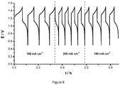
- FIG. 8 shows the voltage profile of a battery that combines an identical electrolyte (2,6 dihydroxy-anthraquinone and potassium ferrocyanide) and a microporous separator 4.
- Current densities as high as 200 mA cm -2 were achieved, which is well above the state of the art in redox flow batteries (ca. 100 mA cm -2 ), maintaining an energy efficiency of 69 %.
Landscapes
- Life Sciences & Earth Sciences (AREA)
- Engineering & Computer Science (AREA)
- Manufacturing & Machinery (AREA)
- Sustainable Development (AREA)
- Sustainable Energy (AREA)
- Chemical & Material Sciences (AREA)
- Chemical Kinetics & Catalysis (AREA)
- Electrochemistry (AREA)
- General Chemical & Material Sciences (AREA)
- Fuel Cell (AREA)
Description
- The present invention relates to the field of batteries. More specifically, the present invention relates to the field of redox-flow batteries intended to decrease the cost of the electrochemical reactor of alkaline flow batteries while maintaining long cycle life.
- Energy storage technologies have become of vital importance for a variety of applications ranging from integration of intermittent renewable energy sources in the electrical grid to portable electronics. For stationary energy storage applications, redox flow batteries (RFB) are especially suitable due to the long cycle life and the independent scalability of energy and power. In an RFB, electrical energy is stored as chemical energy in electroactive species that are dissolved in the electrolyte. The state-of-art RFB is the all-vanadium redox flow battery (AVRFB), which employs redox electrolytes consisting in vanadium species dissolved in strong acidic media [1]. Electrochemical performances of AVRFBs are competitive for stationary applications; however, vanadium is considered to be a strategic/critical material for the US government [2] as well as the EU commission [3].
- In addition, the corrosive vanadium electrolytes are not environmentally friendly. Therefore, finding alternative chemistries for redox flow battery has become of tremendous interest. Electroactive species based on organic molecules and non-critical elements in alkaline media have attracted much attention in recent years. Several chemistries have been demonstrated to deliver promising performances. All these systems use potassium ferrocyanide (a food additive, see e.g. [12]) as active species in the positive compartment and an organic redox compound in the negative compartment, including anthraquinone - K4Fe(CN)6 [4] vitamin B- derivatives - K4Fe(CN)6 [5] alloxazine - K4Fe(CN)6 [6] and phenazine-derivatives - K4Fe(CN)6 [7].
- Cation-selective membranes (CSMs) are the state-of-the art element to separate and avoid short-circuit between positive and negative electrodes in alkaline flow batteries. However, CSMs are expensive (e.g. the commercial product named Nafion® which is a brand name for a sulfonated tetrafluoroethylene-based fluoropolymer-copolymer discovered in the late 1960s by Walther Grot of DuPont). Indeed, CSMs are the most expensive element in the electrochemical reactor and the major contributor to the cost of the stack model [8][9]. In addition, the ionic conductivity of these cation-selective membranes in alkaline media is lower than that in acid media due to the larger size of the K+ and Na+, with respect to H+, limiting the maximum current density at which the electrochemical reactor can be operated. The operating current density has a tremendous impact in the cost of the stack as well; the lower the current density, the larger reactor area and the higher cost.
- In alkaline media, this technical problem has solely been addressed by increasing the ionic conductivity of CSMs by subjecting the membrane to chemical treatments [7]. However, these approaches only lead to incremental improvements since current densities were limited to 100 mA cm-2. In neutral pH, the use of cheap microporous separators (MPSs) was enabled by anchored electro-active species in a polymer chain [10]. If the size of the polymer is larger than the pore size of a microporous separators, crossing of species between compartments will be prevented by size exclusion.
- The document
US2018358621A1 discloses an organic flow cell battery having a material comprising an organic molecule that can be used as the electroactive redox material for both electrodes of the battery. By enabling two-electron processes both of the oxidation and reduction to occur in a single molecule, a total of 4-electron transitions is achieved, which allows the organic molecule to be used on both sides of the separator, reducing material costs and allowing the battery to be charge in either direction with equal ease. - It is an object of the invention to provide an alkaline flow battery assembly to solve the technical problems of the prior art. More concretely, the cation-selective membranes (CSMs) currently used in alkaline flow batteries are expensive. Indeed, CSMs are the most expensive element in the electrochemical reactor and the major contributor to the cost of the stack model. In addition, the ionic conductivity of these cation-selective membranes in alkaline media is lower than that in acid media due to the larger size of the K+ and Na+, with respect to H+, limiting the maximum current density at which the electrochemical reactor can be operated. The operating current density has a tremendous impact in the cost of the stack as well; the lower the current density, the larger reactor area and the higher cost. The technical problem is solved by the assembly of
claim 1. In the dependent claims it is disclosed other embodiments of the assembly. - The present invention is based on the use of cheap microporous separators (MPSs), instead of expensive CSMs, will result in remarkable decrease in cost. In addition, the conductivity of Microporous separator is expected to be much higher than that of CSMs in alkaline media, which will allow the battery to be operated at higher current densities. However, the crossing of species over microporous separators is not selective to cations, but also allows active redox species to diffuse through microporous separators driven by concentration gradient of active species between the two compartments as a result, the installed energy capacity of the battery will gradually decrease falling below specifications relatively fast.
- The present invention proposes the combination of identical redox electrolytes composed of two electro-active species and microporous separators. The use of identical redox electrolytes (IREs) in the two compartments will cancel the concentration gradient of active species that drives diffusion across the microporous separators. In addition, IREs will allow balancing of electrolyte, which is currently another limitation in alkaline flow batteries. So, it is possible to reach a battery with cycle-life.
- The invention brings three main advantages over the state-of-the-art in alkaline flow batteries: (a) Cost of the electrochemical reactor is remarkable decreased by using MPSs, which are two-order of magnitude cheaper than currently used CSMs; (b) the maximum operating current density is also increased due to the higher ionic conductivity of MPSs in alkaline media. An increase in current density leads to smaller size of the electrochemical reactor and, thus, lower cost; and (c) the maximum operating temperature is increased. CSMs start to lose selectivity above 40 °C. This is not an issue in vanadium-flow batteries because the operating temperature is usually limited to 35 °C due to the precipitation of vanadium species above this temperature. However, the solubility of emerging electro-active species increases with increased temperature. Thus, it is beneficial to increase the maximum operating temperature so that energy losses in cooling down the systems can be minimized.
- There follows a very brief description of a series of drawings that help to provide a better understanding of the invention and which are associated expressly with an embodiment of said invention that is presented as a non-limiting example thereof.
-
Figure 1 . Scheme of the alkaline flow battery assembly object of the present invention. -
Figure 2 . Schematic illustration of an identical electrolyte. Species A and B are electro-active in the negative and positive compartment, respectively. The presence of species B and A in the negative and positive compartment, respectively, allows the concentration gradient to be canceled minimizing the crossover of species between the two compartments. -
Figure 3 . Voltage profile of the first charge-discharge cycle of an alkaline flow battery using identical electrolyte based on (a) 2,5 dihydroxy- benzoquinone and potassium ferrocyanide and (b) phenazine-derivative and potassium ferrocyanide. -
Figure 4. (a) Voltage profile of a charge-discharge cycle and (b) evolution of the energy density with the number of cycles for an alkaline flow battery using identical electrolyte based on 2 hydroxy- anthraquinone and potassium ferrocyanide. -
Figure 5. (a) Voltage profile of a charge-discharge cycle and (b) evolution of the energy density with the number of cycles for an alkaline flow battery using identical electrolyte based on 2,6 dihydroxy- anthraquinone and potassium ferrocyanide. -
Figure 6. (a) Voltage profile of a charge-discharge cycle and (b) evolution of the energy density with the number of cycles for an alkaline flow battery using identical electrolyte based on 2 hydroxy- anthraquinone and potassium ferrocyanide. -
Figure 7 . Evolution of energy density with number of cycles of an alkaline flow battery using identical electrolyte based on 2,6 dihydroxy- anthraquinone and potassium ferrocyanide and an MPS. -
Figure 8 . Voltage profile of an alkaline flow battery using identical electrolyte based on 2,6 dihydroxy- anthraquinone and potassium ferrocyanide and MPS at 150, 180 and 200 mA cm-2. - In the prior art, batteries can be categorized in sealed (e.g. Li-ion and NiMH batteries) and redox flux batteries. In flow batteries, electro-active species are stored in external reservoirs and pumped into the electrochemical reactor for energy conversion -electrochemical conversion-. Active species are typically dissolved in the electrolyte of flow batteries so that they can be easily transferred between external reservoir and the electrochemical reactor. The CSMs (cation-selective membranes) are needed to confine active species in the electrolyte of the positive and negative compartment avoiding mixing of charged species. On the other hand, high-energy solid active species can be used in sealed batteries since these species do not need to be moved. Solid active material is easily confined in the positive and negative compartment by using microporous separators that avoid mixing of charged species simply by size exclusion: solid active materials are larger than pore size of the microporous separator. Consequently, expensive CSMs (300$ - 400$ m-2) are typically used in redox flow batteries while cheap microporous separator (3$ - 4$ m-2) can be used in sealed batteries.
- In alkaline media, the lower ionic conductivity of CSMs with respect to acidic media reduces the maximum operating current density and thus increases the size of the electrochemical reactor. Therefore, solutions need to be found if alkaline flow batteries are to be economically competitive since large areas of expensive CSMs are currently needed. Substitution of CSMs by microporous separators could lead to a remarkable decrease in cost but mixing of positive and negative electrolyte will gradually occur since microporous separator allows dissolved active species to diffuse through it.
- In the
figure 1 it is shown a schematic view of an alkaline flow battery assembly according with the invention. The assembly comprises an electrochemical reactor, comprising apositive compartment 5 and anegative compartment 3 separated by amicroporous separator 4. Thepositive compartment 5 further comprises apositive electrode 5a and houses catholyte 5b. Analogously, thenegative compartment 3 comprises anegative electrode 3a and houses anolyte 3b. Thepositive electrode 5a and thenegative electrode 3a are connected to a power/load source 6. - Advantageously, the
positive compartment 5 is connected through aconduct 2a with acontainer 2 in such a way that thecontainer 2 can provide catholyte stored in thecontainer 2 to thepositive compartment 5 in fluid communication. Analogously, thenegative compartment 3 is connected through aconduct 1a to acontainer 1 in such a way that thecontainer 1 can provide anolyte stored in thecontainer 1 to thenegative compartment 3 in fluid communication. The assembly is further characterized by the fact that the anolyte and the catholyte are an identical alkaline redox solution. - In a typical state-of-the-art redox flow battery, a first electro-active species A is employed in the negative compartment (anolyte) and a second electro-active species B is used in the positive compartment (catholyte). As the energy density of the flow battery increases with increasing concentration of electro-active species, the concentration of both electro-active species is as high as possible. This difference in concentration drives diffusion of electro-active species to the opposite compartment: species A diffuse to the positive compartment whereas species B diffuse to the negative compartment. The crossing of species leads to a fast decrease in the installed energy capacity of the systems below specifications.
- However, the invention advantageously proposes the use of identical electrolytes (identical alkaline redox solutions) for the positive and
negative compartments figure 2 although species A is not electro-active in thepositive compartment 5 nor the species B in thenegative compartment 3, their presence in the opposite compartment cancels the concentration gradient of electro-active species between compartments, which enables the use of cheapmicroporous separators 4 in alkaline flow batteries. In addition, balancing of electrolyte of negative andpositive compartment - Nonetheless, it is founded out that all electro-active species are not compatible, which make a preliminary study of compatibility necessary. It is understood in the context of the present invention that "compatible" or "compatibility" between two electro-active species A and B means that the presence of species B and A in the negative and positive compartment, does not alter the electrochemical performance of the individual species, e.g. electrochemical reversibility upon oxidation and reduction. As way of example, a flow battery based on 2,5 dihydroxy-benzoquinone (species A) and potassium ferrocyanide (species B) was reported to deliver promising performance using CSM and having each electro-active species confined in its corresponding compartment [11]. However, the alkaline flow battery using identical electrolyte based on these species does not function
-figure 3a-. When one of the species is charged, an irreversible reaction with the other species in discharge state takes place. Another example of incompatibility in identical electrolyte between two electroactive species is the 7,8-dihydroxyphenazine-2-sulfonic acid (species A) and potassium ferrocyanide (species B) -figure 3b - which also was reported to function when each electro-active species is confined in each compartment [7]. - On the other hand, anthraquinones and potassium ferrocyanide were found to be compatible as species A and B, respectively, in identical electrolytes.
Figure 4 shows the voltage profile and the evolution of the energy density upon cycling for an alkaline battery using identical electrolyte based on 2 hydroxy-anthraquinone and potassium ferrocyanide as species A and B, respectively. Both species are present in bothcompartments Figure 5 ). It should be noted that an electrochemical reactor containing CSM instead of amicroporous separator 4 was used to simplify the compatibility studies. - An alkaline flow battery using
microporous separator 4 and identical electrolyte based on 2 hydroxy-anthraquinone and potassium ferrocyanide was evaluated (Figure 6 ). This particular experiment was carried out in static conditions to avoid crossover the electrolyte due to pressure differences between the two compartments.Figure 6 shows that the capacity fade is negligible upon 1.000 cycles demonstrating the compatibility between this identical electrolyte and the use ofmicroporous separators 4. - An alkaline flow battery using a
microporous separator 4 and identical electrolyte based on 2,6 dihydroxy-anthraquinone and potassium ferrocyanide was evaluated (Figure 7 ). After 80 cycles, the energy density of the systems decreased rapidly due to unbalancing of the volume of electrolyte in positive and negative compartment. After 500 cycles, the identical electrolyte was rebalanced by simply mixing the content of both reservoirs. The energy density of the systems was recovered showing that specifications of the battery are retained by combining identical electrolyte andmicroporous separator 4. - An additional benefit of using a
microporous separator 4 is the high current density at which the systems can be operated.Figure 8 shows the voltage profile of a battery that combines an identical electrolyte (2,6 dihydroxy-anthraquinone and potassium ferrocyanide) and amicroporous separator 4. Current densities as high as 200 mA cm-2 were achieved, which is well above the state of the art in redox flow batteries (ca. 100 mA cm-2), maintaining an energy efficiency of 69 %. The difference in ionic areal resistance between CSM (Nafion ® 212) and a microporous separator (Celgard ® 3401) was measured to be 2.3 Ω cm-2. When operating at 200 mA cm-2 the overpotential of a cell using a CSM instead of a microporous separator will be 460 mV higher, which will lead to impede charging the battery due to the promotion of side reactions, e.g. hydrogen evolution reaction. -
- [1] Ding et al., J. Phys. Chem. Lett. 2013, 4, 1281
- [2] Final List of Critical Minerals 2018: https://www.federalregister.gov/documents/2018/05/18/2018-10667/final-list-of-critical-minerals-2018
- [3] List of Critical Raw Materials for the EU: https://eur-lex.europa.eu/legal-content/EN/TXT/?uri=CELEX:52017DC0490
- [4] Lin, et al. Science, 2015, 349. 1529-1532
- [5] Orita, et al., Nat. Commun. 2016, 7, 13230
- [6] Lin, et al., Nat.
- [7] Hollas, et al., Nat.
- [8] Viswanathan et al., J. Power Sources, 2014, 247, 1040
- [9] Ha et al., J. Power Sources, 2015, 296, 122
- [10] Janoschka, et al., Nature, 2015, 527, 78.
- [11] Yang, et al., Adv. Energy Mater., 2017, 8, 1702056
- [12] World Health Organ. Tech. Rep. Ser., 1974, 539, 1-40
Claims (5)
- An alkaline flow battery assembly comprising an electrochemical reactor including a positive compartment (5) and a negative compartment (3);wherein the positive compartment (5) comprises a positive electrode (5a) and houses catholyte (5b) whereas the negative compartment (3) comprises a negative electrode (3a) and houses anolyte (3b);wherein the negative compartment (3) is connected through a conduct (1a) in fluid communication to a first container (1) storing anolyte whereas the positive compartment (5) is connected through a conduct (2a) in fluid communication with a second container (2) storing catholyte;characterized in that the anolyte and the catholyte are alkaline redox solutions both comprising a first electro-active species A and a second electro-active species B, being the species A, an anthraquinone-based compound, and the species B a potassium ferrocyanide; and wherein the negative compartment (3) and the positive compartment (5) are separated by means of a microporous separator (4).
- The assembly of claim 1 wherein the anthraquinone is one selected from: 2,6 dihydroxy-anthraquinone or 2 dihydroxy-anthraquinone.
- The assembly of any of claims 1 to 2 wherein it is arranged to balance the anolyte and the catholyte by simply mixing of the content of the first and second containers (1,2).
- Use of an alkaline flow battery assembly according to any of the claims 1-3 to store electricity connecting the positive electrode (5a) and the negative electrode (3a) to a power source (6).
- Use of an alkaline flow battery assembly according to any of the claims 1-3 to deliver electricity connecting the positive electrode (5a) and the negative electrode (3a) to a load (6).
Priority Applications (5)
| Application Number | Priority Date | Filing Date | Title |
|---|---|---|---|
| EP19382473.7A EP3748753B1 (en) | 2019-06-06 | 2019-06-06 | An alkaline flow battery assembly |
| DK19382473.7T DK3748753T3 (en) | 2019-06-06 | 2019-06-06 | AN ALKALINE FLOW BATTERY DEVICE |
| ES19382473T ES2910876T3 (en) | 2019-06-06 | 2019-06-06 | A set of alkaline flow batteries |
| PCT/ES2020/070277 WO2020245478A1 (en) | 2019-06-06 | 2020-04-29 | Alkaline flow battery assembly |
| US17/615,791 US20220255093A1 (en) | 2019-06-06 | 2020-04-29 | An alkaline flow battery assembly |
Applications Claiming Priority (1)
| Application Number | Priority Date | Filing Date | Title |
|---|---|---|---|
| EP19382473.7A EP3748753B1 (en) | 2019-06-06 | 2019-06-06 | An alkaline flow battery assembly |
Publications (2)
| Publication Number | Publication Date |
|---|---|
| EP3748753A1 EP3748753A1 (en) | 2020-12-09 |
| EP3748753B1 true EP3748753B1 (en) | 2022-01-05 |
Family
ID=66821158
Family Applications (1)
| Application Number | Title | Priority Date | Filing Date |
|---|---|---|---|
| EP19382473.7A Not-in-force EP3748753B1 (en) | 2019-06-06 | 2019-06-06 | An alkaline flow battery assembly |
Country Status (5)
| Country | Link |
|---|---|
| US (1) | US20220255093A1 (en) |
| EP (1) | EP3748753B1 (en) |
| DK (1) | DK3748753T3 (en) |
| ES (1) | ES2910876T3 (en) |
| WO (1) | WO2020245478A1 (en) |
Family Cites Families (4)
| Publication number | Priority date | Publication date | Assignee | Title |
|---|---|---|---|---|
| US8628880B2 (en) * | 2010-09-28 | 2014-01-14 | Battelle Memorial Institute | Redox flow batteries based on supporting solutions containing chloride |
| US10079401B2 (en) * | 2014-03-24 | 2018-09-18 | Cornell University | Symmetric redox flow battery containing organic redox active molecule |
| US10403895B2 (en) * | 2014-12-23 | 2019-09-03 | Cambridge Display Technology Limited | Organic flow cell batteries and materials for use in same |
| US20180048011A1 (en) * | 2015-03-06 | 2018-02-15 | President And Fellows Of Harvard College | HIGH pH ORGANIC FLOW BATTERY |
-
2019
- 2019-06-06 EP EP19382473.7A patent/EP3748753B1/en not_active Not-in-force
- 2019-06-06 DK DK19382473.7T patent/DK3748753T3/en active
- 2019-06-06 ES ES19382473T patent/ES2910876T3/en active Active
-
2020
- 2020-04-29 WO PCT/ES2020/070277 patent/WO2020245478A1/en not_active Ceased
- 2020-04-29 US US17/615,791 patent/US20220255093A1/en not_active Abandoned
Also Published As
| Publication number | Publication date |
|---|---|
| US20220255093A1 (en) | 2022-08-11 |
| EP3748753A1 (en) | 2020-12-09 |
| WO2020245478A1 (en) | 2020-12-10 |
| ES2910876T3 (en) | 2022-05-13 |
| DK3748753T3 (en) | 2022-03-21 |
Similar Documents
| Publication | Publication Date | Title |
|---|---|---|
| CN101185185B (en) | Secondary battery, power supply system using same, and method for using power supply system | |
| Wang et al. | Li‐redox flow batteries based on hybrid electrolytes: at the cross road between Li‐ion and redox flow batteries | |
| US9917323B2 (en) | Double-membrane triple-electrolyte redox flow battery design | |
| Yuan et al. | Perspective of alkaline zinc-based flow batteries | |
| Huang et al. | A redox flow lithium battery based on the redox targeting reactions between LiFePO 4 and iodide | |
| US9130218B2 (en) | Hybrid energy storage systems utilizing redox active organic compounds | |
| US10411286B2 (en) | Alkali/oxidant battery | |
| CN104854731B (en) | It is characterized as the electrochemical energy storage system of high open circuit voltage | |
| US9431672B2 (en) | Molten-salt electrolyte unitized regenerative hydrogen-halogen fuel cell with anion transfer | |
| WO2015150784A1 (en) | Hybrid electrochemical energy device | |
| US20150349369A1 (en) | High-Energy-Density, Nonaqueous, Redox Flow Batteries Having Iodine-based Species | |
| CN104854732A (en) | Electrochemical energy storage systems and methods featuring large negative half-cell potentials | |
| EP3748753B1 (en) | An alkaline flow battery assembly | |
| US11705571B2 (en) | Foil-based redox flow battery | |
| KR101491784B1 (en) | Method of operating chemical flow battery | |
| KR20190006375A (en) | Redox Flow Battery using Sodium-Biphenyl | |
| KR102829049B1 (en) | Process of improving perfomance of vanadium redox flow battery | |
| US20240429420A1 (en) | Precipitate control, active species cross-over management and rebalancing strategies for redox flow batteries | |
| US9537192B2 (en) | Battery with low temperature molten salt (LTMS) cathode | |
| CN112864437B (en) | A kind of iron-lead single flow battery and preparation method thereof | |
| Li et al. | pH Differential Power Sources with Electrochemical Neutralisation | |
| Krishnasamy et al. | Types and classifications of batteries | |
| Tian | Liquid Flow Batteries: Principles, Applications, and Future Prospects | |
| Dell | Materials Development Division, AERE Harwell, Oxfordshire OX11 ORA, United Kingdom. | |
| WO2018031689A1 (en) | Near ambient temperature, high potential secondary battery with liquid electrode materials separated by a solid electrolyte |
Legal Events
| Date | Code | Title | Description |
|---|---|---|---|
| PUAI | Public reference made under article 153(3) epc to a published international application that has entered the european phase |
Free format text: ORIGINAL CODE: 0009012 |
|
| STAA | Information on the status of an ep patent application or granted ep patent |
Free format text: STATUS: REQUEST FOR EXAMINATION WAS MADE |
|
| 17P | Request for examination filed |
Effective date: 20200206 |
|
| AK | Designated contracting states |
Kind code of ref document: A1 Designated state(s): AL AT BE BG CH CY CZ DE DK EE ES FI FR GB GR HR HU IE IS IT LI LT LU LV MC MK MT NL NO PL PT RO RS SE SI SK SM TR |
|
| AX | Request for extension of the european patent |
Extension state: BA ME |
|
| GRAP | Despatch of communication of intention to grant a patent |
Free format text: ORIGINAL CODE: EPIDOSNIGR1 |
|
| STAA | Information on the status of an ep patent application or granted ep patent |
Free format text: STATUS: GRANT OF PATENT IS INTENDED |
|
| INTG | Intention to grant announced |
Effective date: 20210803 |
|
| GRAS | Grant fee paid |
Free format text: ORIGINAL CODE: EPIDOSNIGR3 |
|
| GRAA | (expected) grant |
Free format text: ORIGINAL CODE: 0009210 |
|
| STAA | Information on the status of an ep patent application or granted ep patent |
Free format text: STATUS: THE PATENT HAS BEEN GRANTED |
|
| AK | Designated contracting states |
Kind code of ref document: B1 Designated state(s): AL AT BE BG CH CY CZ DE DK EE ES FI FR GB GR HR HU IE IS IT LI LT LU LV MC MK MT NL NO PL PT RO RS SE SI SK SM TR |
|
| REG | Reference to a national code |
Ref country code: GB Ref legal event code: FG4D |
|
| REG | Reference to a national code |
Ref country code: CH Ref legal event code: EP |
|
| REG | Reference to a national code |
Ref country code: AT Ref legal event code: REF Ref document number: 1461377 Country of ref document: AT Kind code of ref document: T Effective date: 20220115 |
|
| REG | Reference to a national code |
Ref country code: DE Ref legal event code: R096 Ref document number: 602019010672 Country of ref document: DE |
|
| REG | Reference to a national code |
Ref country code: IE Ref legal event code: FG4D |
|
| REG | Reference to a national code |
Ref country code: NL Ref legal event code: FP |
|
| REG | Reference to a national code |
Ref country code: DK Ref legal event code: T3 Effective date: 20220315 |
|
| REG | Reference to a national code |
Ref country code: LT Ref legal event code: MG9D |
|
| REG | Reference to a national code |
Ref country code: ES Ref legal event code: FG2A Ref document number: 2910876 Country of ref document: ES Kind code of ref document: T3 Effective date: 20220513 |
|
| REG | Reference to a national code |
Ref country code: AT Ref legal event code: MK05 Ref document number: 1461377 Country of ref document: AT Kind code of ref document: T Effective date: 20220105 |
|
| PG25 | Lapsed in a contracting state [announced via postgrant information from national office to epo] |
Ref country code: SE Free format text: LAPSE BECAUSE OF FAILURE TO SUBMIT A TRANSLATION OF THE DESCRIPTION OR TO PAY THE FEE WITHIN THE PRESCRIBED TIME-LIMIT Effective date: 20220105 Ref country code: RS Free format text: LAPSE BECAUSE OF FAILURE TO SUBMIT A TRANSLATION OF THE DESCRIPTION OR TO PAY THE FEE WITHIN THE PRESCRIBED TIME-LIMIT Effective date: 20220105 Ref country code: PT Free format text: LAPSE BECAUSE OF FAILURE TO SUBMIT A TRANSLATION OF THE DESCRIPTION OR TO PAY THE FEE WITHIN THE PRESCRIBED TIME-LIMIT Effective date: 20220505 Ref country code: NO Free format text: LAPSE BECAUSE OF FAILURE TO SUBMIT A TRANSLATION OF THE DESCRIPTION OR TO PAY THE FEE WITHIN THE PRESCRIBED TIME-LIMIT Effective date: 20220405 Ref country code: LT Free format text: LAPSE BECAUSE OF FAILURE TO SUBMIT A TRANSLATION OF THE DESCRIPTION OR TO PAY THE FEE WITHIN THE PRESCRIBED TIME-LIMIT Effective date: 20220105 Ref country code: HR Free format text: LAPSE BECAUSE OF FAILURE TO SUBMIT A TRANSLATION OF THE DESCRIPTION OR TO PAY THE FEE WITHIN THE PRESCRIBED TIME-LIMIT Effective date: 20220105 Ref country code: BG Free format text: LAPSE BECAUSE OF FAILURE TO SUBMIT A TRANSLATION OF THE DESCRIPTION OR TO PAY THE FEE WITHIN THE PRESCRIBED TIME-LIMIT Effective date: 20220405 |
|
| PG25 | Lapsed in a contracting state [announced via postgrant information from national office to epo] |
Ref country code: PL Free format text: LAPSE BECAUSE OF FAILURE TO SUBMIT A TRANSLATION OF THE DESCRIPTION OR TO PAY THE FEE WITHIN THE PRESCRIBED TIME-LIMIT Effective date: 20220105 Ref country code: LV Free format text: LAPSE BECAUSE OF FAILURE TO SUBMIT A TRANSLATION OF THE DESCRIPTION OR TO PAY THE FEE WITHIN THE PRESCRIBED TIME-LIMIT Effective date: 20220105 Ref country code: FI Free format text: LAPSE BECAUSE OF FAILURE TO SUBMIT A TRANSLATION OF THE DESCRIPTION OR TO PAY THE FEE WITHIN THE PRESCRIBED TIME-LIMIT Effective date: 20220105 Ref country code: AT Free format text: LAPSE BECAUSE OF FAILURE TO SUBMIT A TRANSLATION OF THE DESCRIPTION OR TO PAY THE FEE WITHIN THE PRESCRIBED TIME-LIMIT Effective date: 20220105 |
|
| PG25 | Lapsed in a contracting state [announced via postgrant information from national office to epo] |
Ref country code: IS Free format text: LAPSE BECAUSE OF FAILURE TO SUBMIT A TRANSLATION OF THE DESCRIPTION OR TO PAY THE FEE WITHIN THE PRESCRIBED TIME-LIMIT Effective date: 20220505 |
|
| REG | Reference to a national code |
Ref country code: DE Ref legal event code: R097 Ref document number: 602019010672 Country of ref document: DE |
|
| PG25 | Lapsed in a contracting state [announced via postgrant information from national office to epo] |
Ref country code: SM Free format text: LAPSE BECAUSE OF FAILURE TO SUBMIT A TRANSLATION OF THE DESCRIPTION OR TO PAY THE FEE WITHIN THE PRESCRIBED TIME-LIMIT Effective date: 20220105 Ref country code: SK Free format text: LAPSE BECAUSE OF FAILURE TO SUBMIT A TRANSLATION OF THE DESCRIPTION OR TO PAY THE FEE WITHIN THE PRESCRIBED TIME-LIMIT Effective date: 20220105 Ref country code: RO Free format text: LAPSE BECAUSE OF FAILURE TO SUBMIT A TRANSLATION OF THE DESCRIPTION OR TO PAY THE FEE WITHIN THE PRESCRIBED TIME-LIMIT Effective date: 20220105 Ref country code: EE Free format text: LAPSE BECAUSE OF FAILURE TO SUBMIT A TRANSLATION OF THE DESCRIPTION OR TO PAY THE FEE WITHIN THE PRESCRIBED TIME-LIMIT Effective date: 20220105 Ref country code: CZ Free format text: LAPSE BECAUSE OF FAILURE TO SUBMIT A TRANSLATION OF THE DESCRIPTION OR TO PAY THE FEE WITHIN THE PRESCRIBED TIME-LIMIT Effective date: 20220105 |
|
| PLBE | No opposition filed within time limit |
Free format text: ORIGINAL CODE: 0009261 |
|
| STAA | Information on the status of an ep patent application or granted ep patent |
Free format text: STATUS: NO OPPOSITION FILED WITHIN TIME LIMIT |
|
| PG25 | Lapsed in a contracting state [announced via postgrant information from national office to epo] |
Ref country code: AL Free format text: LAPSE BECAUSE OF FAILURE TO SUBMIT A TRANSLATION OF THE DESCRIPTION OR TO PAY THE FEE WITHIN THE PRESCRIBED TIME-LIMIT Effective date: 20220105 |
|
| 26N | No opposition filed |
Effective date: 20221006 |
|
| PG25 | Lapsed in a contracting state [announced via postgrant information from national office to epo] |
Ref country code: MC Free format text: LAPSE BECAUSE OF FAILURE TO SUBMIT A TRANSLATION OF THE DESCRIPTION OR TO PAY THE FEE WITHIN THE PRESCRIBED TIME-LIMIT Effective date: 20220105 |
|
| REG | Reference to a national code |
Ref country code: CH Ref legal event code: PL |
|
| REG | Reference to a national code |
Ref country code: BE Ref legal event code: MM Effective date: 20220630 |
|
| PG25 | Lapsed in a contracting state [announced via postgrant information from national office to epo] |
Ref country code: SI Free format text: LAPSE BECAUSE OF FAILURE TO SUBMIT A TRANSLATION OF THE DESCRIPTION OR TO PAY THE FEE WITHIN THE PRESCRIBED TIME-LIMIT Effective date: 20220105 |
|
| PG25 | Lapsed in a contracting state [announced via postgrant information from national office to epo] |
Ref country code: LU Free format text: LAPSE BECAUSE OF NON-PAYMENT OF DUE FEES Effective date: 20220606 Ref country code: LI Free format text: LAPSE BECAUSE OF NON-PAYMENT OF DUE FEES Effective date: 20220630 Ref country code: IE Free format text: LAPSE BECAUSE OF NON-PAYMENT OF DUE FEES Effective date: 20220606 Ref country code: CH Free format text: LAPSE BECAUSE OF NON-PAYMENT OF DUE FEES Effective date: 20220630 |
|
| PG25 | Lapsed in a contracting state [announced via postgrant information from national office to epo] |
Ref country code: BE Free format text: LAPSE BECAUSE OF NON-PAYMENT OF DUE FEES Effective date: 20220630 |
|
| PG25 | Lapsed in a contracting state [announced via postgrant information from national office to epo] |
Ref country code: IT Free format text: LAPSE BECAUSE OF FAILURE TO SUBMIT A TRANSLATION OF THE DESCRIPTION OR TO PAY THE FEE WITHIN THE PRESCRIBED TIME-LIMIT Effective date: 20220105 |
|
| PGFP | Annual fee paid to national office [announced via postgrant information from national office to epo] |
Ref country code: NL Payment date: 20230629 Year of fee payment: 5 Ref country code: FR Payment date: 20230628 Year of fee payment: 5 Ref country code: DK Payment date: 20230629 Year of fee payment: 5 Ref country code: DE Payment date: 20230629 Year of fee payment: 5 |
|
| PGFP | Annual fee paid to national office [announced via postgrant information from national office to epo] |
Ref country code: GB Payment date: 20230629 Year of fee payment: 5 Ref country code: ES Payment date: 20230703 Year of fee payment: 5 |
|
| PG25 | Lapsed in a contracting state [announced via postgrant information from national office to epo] |
Ref country code: MK Free format text: LAPSE BECAUSE OF FAILURE TO SUBMIT A TRANSLATION OF THE DESCRIPTION OR TO PAY THE FEE WITHIN THE PRESCRIBED TIME-LIMIT Effective date: 20220105 Ref country code: CY Free format text: LAPSE BECAUSE OF FAILURE TO SUBMIT A TRANSLATION OF THE DESCRIPTION OR TO PAY THE FEE WITHIN THE PRESCRIBED TIME-LIMIT Effective date: 20220105 |
|
| PG25 | Lapsed in a contracting state [announced via postgrant information from national office to epo] |
Ref country code: HU Free format text: LAPSE BECAUSE OF FAILURE TO SUBMIT A TRANSLATION OF THE DESCRIPTION OR TO PAY THE FEE WITHIN THE PRESCRIBED TIME-LIMIT; INVALID AB INITIO Effective date: 20190606 |
|
| PG25 | Lapsed in a contracting state [announced via postgrant information from national office to epo] |
Ref country code: MT Free format text: LAPSE BECAUSE OF FAILURE TO SUBMIT A TRANSLATION OF THE DESCRIPTION OR TO PAY THE FEE WITHIN THE PRESCRIBED TIME-LIMIT Effective date: 20220105 |
|
| PG25 | Lapsed in a contracting state [announced via postgrant information from national office to epo] |
Ref country code: GR Free format text: LAPSE BECAUSE OF NON-PAYMENT OF DUE FEES Effective date: 20220105 |
|
| PG25 | Lapsed in a contracting state [announced via postgrant information from national office to epo] |
Ref country code: GR Free format text: LAPSE BECAUSE OF NON-PAYMENT OF DUE FEES Effective date: 20220105 |
|
| REG | Reference to a national code |
Ref country code: DE Ref legal event code: R119 Ref document number: 602019010672 Country of ref document: DE |
|
| REG | Reference to a national code |
Ref country code: DK Ref legal event code: EBP Effective date: 20240630 |
|
| REG | Reference to a national code |
Ref country code: NL Ref legal event code: MM Effective date: 20240701 |
|
| GBPC | Gb: european patent ceased through non-payment of renewal fee |
Effective date: 20240606 |
|
| PG25 | Lapsed in a contracting state [announced via postgrant information from national office to epo] |
Ref country code: NL Free format text: LAPSE BECAUSE OF NON-PAYMENT OF DUE FEES Effective date: 20240701 |
|
| PG25 | Lapsed in a contracting state [announced via postgrant information from national office to epo] |
Ref country code: NL Free format text: LAPSE BECAUSE OF NON-PAYMENT OF DUE FEES Effective date: 20240701 |
|
| PG25 | Lapsed in a contracting state [announced via postgrant information from national office to epo] |
Ref country code: DE Free format text: LAPSE BECAUSE OF NON-PAYMENT OF DUE FEES Effective date: 20250101 |
|
| PG25 | Lapsed in a contracting state [announced via postgrant information from national office to epo] |
Ref country code: FR Free format text: LAPSE BECAUSE OF NON-PAYMENT OF DUE FEES Effective date: 20240630 |
|
| PG25 | Lapsed in a contracting state [announced via postgrant information from national office to epo] |
Ref country code: GB Free format text: LAPSE BECAUSE OF NON-PAYMENT OF DUE FEES Effective date: 20240606 |
|
| PG25 | Lapsed in a contracting state [announced via postgrant information from national office to epo] |
Ref country code: DK Free format text: LAPSE BECAUSE OF NON-PAYMENT OF DUE FEES Effective date: 20240630 |
|
| REG | Reference to a national code |
Ref country code: ES Ref legal event code: FD2A Effective date: 20250728 |
|
| PG25 | Lapsed in a contracting state [announced via postgrant information from national office to epo] |
Ref country code: ES Free format text: LAPSE BECAUSE OF NON-PAYMENT OF DUE FEES Effective date: 20240607 |
|
| PG25 | Lapsed in a contracting state [announced via postgrant information from national office to epo] |
Ref country code: TR Free format text: LAPSE BECAUSE OF FAILURE TO SUBMIT A TRANSLATION OF THE DESCRIPTION OR TO PAY THE FEE WITHIN THE PRESCRIBED TIME-LIMIT Effective date: 20220105 |