EP3748450B1 - Data driven machine learning for modeling aircraft sensors - Google Patents
Data driven machine learning for modeling aircraft sensors Download PDFInfo
- Publication number
- EP3748450B1 EP3748450B1 EP20172243.6A EP20172243A EP3748450B1 EP 3748450 B1 EP3748450 B1 EP 3748450B1 EP 20172243 A EP20172243 A EP 20172243A EP 3748450 B1 EP3748450 B1 EP 3748450B1
- Authority
- EP
- European Patent Office
- Prior art keywords
- component
- components
- real
- predictive model
- time
- Prior art date
- Legal status (The legal status is an assumption and is not a legal conclusion. Google has not performed a legal analysis and makes no representation as to the accuracy of the status listed.)
- Active
Links
Images


Classifications
-
- B—PERFORMING OPERATIONS; TRANSPORTING
- B64—AIRCRAFT; AVIATION; COSMONAUTICS
- B64D—EQUIPMENT FOR FITTING IN OR TO AIRCRAFT; FLIGHT SUITS; PARACHUTES; ARRANGEMENT OR MOUNTING OF POWER PLANTS OR PROPULSION TRANSMISSIONS IN AIRCRAFT
- B64D45/00—Aircraft indicators or protectors not otherwise provided for
-
- G—PHYSICS
- G05—CONTROLLING; REGULATING
- G05B—CONTROL OR REGULATING SYSTEMS IN GENERAL; FUNCTIONAL ELEMENTS OF SUCH SYSTEMS; MONITORING OR TESTING ARRANGEMENTS FOR SUCH SYSTEMS OR ELEMENTS
- G05B23/00—Testing or monitoring of control systems or parts thereof
- G05B23/02—Electric testing or monitoring
- G05B23/0205—Electric testing or monitoring by means of a monitoring system capable of detecting and responding to faults
- G05B23/0218—Electric testing or monitoring by means of a monitoring system capable of detecting and responding to faults characterised by the fault detection method dealing with either existing or incipient faults
- G05B23/0243—Electric testing or monitoring by means of a monitoring system capable of detecting and responding to faults characterised by the fault detection method dealing with either existing or incipient faults model based detection method, e.g. first-principles knowledge model
- G05B23/0254—Electric testing or monitoring by means of a monitoring system capable of detecting and responding to faults characterised by the fault detection method dealing with either existing or incipient faults model based detection method, e.g. first-principles knowledge model based on a quantitative model, e.g. mathematical relationships between inputs and outputs; functions: observer, Kalman filter, residual calculation, Neural Networks
-
- G—PHYSICS
- G06—COMPUTING OR CALCULATING; COUNTING
- G06F—ELECTRIC DIGITAL DATA PROCESSING
- G06F2218/00—Aspects of pattern recognition specially adapted for signal processing
- G06F2218/12—Classification; Matching
-
- G—PHYSICS
- G05—CONTROLLING; REGULATING
- G05B—CONTROL OR REGULATING SYSTEMS IN GENERAL; FUNCTIONAL ELEMENTS OF SUCH SYSTEMS; MONITORING OR TESTING ARRANGEMENTS FOR SUCH SYSTEMS OR ELEMENTS
- G05B23/00—Testing or monitoring of control systems or parts thereof
- G05B23/02—Electric testing or monitoring
-
- B—PERFORMING OPERATIONS; TRANSPORTING
- B64—AIRCRAFT; AVIATION; COSMONAUTICS
- B64F—GROUND OR AIRCRAFT-CARRIER-DECK INSTALLATIONS SPECIALLY ADAPTED FOR USE IN CONNECTION WITH AIRCRAFT; DESIGNING, MANUFACTURING, ASSEMBLING, CLEANING, MAINTAINING OR REPAIRING AIRCRAFT, NOT OTHERWISE PROVIDED FOR; HANDLING, TRANSPORTING, TESTING OR INSPECTING AIRCRAFT COMPONENTS, NOT OTHERWISE PROVIDED FOR
- B64F5/00—Designing, manufacturing, assembling, cleaning, maintaining or repairing aircraft, not otherwise provided for; Handling, transporting, testing or inspecting aircraft components, not otherwise provided for
- B64F5/60—Testing or inspecting aircraft components or systems
-
- G—PHYSICS
- G05—CONTROLLING; REGULATING
- G05B—CONTROL OR REGULATING SYSTEMS IN GENERAL; FUNCTIONAL ELEMENTS OF SUCH SYSTEMS; MONITORING OR TESTING ARRANGEMENTS FOR SUCH SYSTEMS OR ELEMENTS
- G05B23/00—Testing or monitoring of control systems or parts thereof
- G05B23/02—Electric testing or monitoring
- G05B23/0205—Electric testing or monitoring by means of a monitoring system capable of detecting and responding to faults
- G05B23/0259—Electric testing or monitoring by means of a monitoring system capable of detecting and responding to faults characterized by the response to fault detection
- G05B23/0283—Predictive maintenance, e.g. involving the monitoring of a system and, based on the monitoring results, taking decisions on the maintenance schedule of the monitored system; Estimating remaining useful life [RUL]
-
- G—PHYSICS
- G06—COMPUTING OR CALCULATING; COUNTING
- G06F—ELECTRIC DIGITAL DATA PROCESSING
- G06F18/00—Pattern recognition
- G06F18/20—Analysing
- G06F18/24—Classification techniques
- G06F18/241—Classification techniques relating to the classification model, e.g. parametric or non-parametric approaches
-
- G—PHYSICS
- G06—COMPUTING OR CALCULATING; COUNTING
- G06N—COMPUTING ARRANGEMENTS BASED ON SPECIFIC COMPUTATIONAL MODELS
- G06N20/00—Machine learning
-
- G—PHYSICS
- G06—COMPUTING OR CALCULATING; COUNTING
- G06N—COMPUTING ARRANGEMENTS BASED ON SPECIFIC COMPUTATIONAL MODELS
- G06N3/00—Computing arrangements based on biological models
- G06N3/02—Neural networks
- G06N3/08—Learning methods
- G06N3/09—Supervised learning
-
- G—PHYSICS
- G06—COMPUTING OR CALCULATING; COUNTING
- G06N—COMPUTING ARRANGEMENTS BASED ON SPECIFIC COMPUTATIONAL MODELS
- G06N5/00—Computing arrangements using knowledge-based models
- G06N5/04—Inference or reasoning models
-
- H—ELECTRICITY
- H04—ELECTRIC COMMUNICATION TECHNIQUE
- H04L—TRANSMISSION OF DIGITAL INFORMATION, e.g. TELEGRAPHIC COMMUNICATION
- H04L67/00—Network arrangements or protocols for supporting network services or applications
- H04L67/50—Network services
- H04L67/56—Provisioning of proxy services
- H04L67/565—Conversion or adaptation of application format or content
-
- B—PERFORMING OPERATIONS; TRANSPORTING
- B64—AIRCRAFT; AVIATION; COSMONAUTICS
- B64D—EQUIPMENT FOR FITTING IN OR TO AIRCRAFT; FLIGHT SUITS; PARACHUTES; ARRANGEMENT OR MOUNTING OF POWER PLANTS OR PROPULSION TRANSMISSIONS IN AIRCRAFT
- B64D45/00—Aircraft indicators or protectors not otherwise provided for
- B64D2045/0085—Devices for aircraft health monitoring, e.g. monitoring flutter or vibration
-
- G—PHYSICS
- G05—CONTROLLING; REGULATING
- G05B—CONTROL OR REGULATING SYSTEMS IN GENERAL; FUNCTIONAL ELEMENTS OF SUCH SYSTEMS; MONITORING OR TESTING ARRANGEMENTS FOR SUCH SYSTEMS OR ELEMENTS
- G05B17/00—Systems involving the use of models or simulators of said systems
- G05B17/02—Systems involving the use of models or simulators of said systems electric
-
- G—PHYSICS
- G06—COMPUTING OR CALCULATING; COUNTING
- G06N—COMPUTING ARRANGEMENTS BASED ON SPECIFIC COMPUTATIONAL MODELS
- G06N20/00—Machine learning
- G06N20/10—Machine learning using kernel methods, e.g. support vector machines [SVM]
-
- G—PHYSICS
- G06—COMPUTING OR CALCULATING; COUNTING
- G06N—COMPUTING ARRANGEMENTS BASED ON SPECIFIC COMPUTATIONAL MODELS
- G06N3/00—Computing arrangements based on biological models
- G06N3/02—Neural networks
- G06N3/08—Learning methods
-
- G—PHYSICS
- G06—COMPUTING OR CALCULATING; COUNTING
- G06N—COMPUTING ARRANGEMENTS BASED ON SPECIFIC COMPUTATIONAL MODELS
- G06N5/00—Computing arrangements using knowledge-based models
- G06N5/01—Dynamic search techniques; Heuristics; Dynamic trees; Branch-and-bound
-
- G—PHYSICS
- G06—COMPUTING OR CALCULATING; COUNTING
- G06N—COMPUTING ARRANGEMENTS BASED ON SPECIFIC COMPUTATIONAL MODELS
- G06N5/00—Computing arrangements using knowledge-based models
- G06N5/02—Knowledge representation; Symbolic representation
- G06N5/022—Knowledge engineering; Knowledge acquisition
- G06N5/025—Extracting rules from data
-
- G—PHYSICS
- G06—COMPUTING OR CALCULATING; COUNTING
- G06N—COMPUTING ARRANGEMENTS BASED ON SPECIFIC COMPUTATIONAL MODELS
- G06N7/00—Computing arrangements based on specific mathematical models
- G06N7/01—Probabilistic graphical models, e.g. probabilistic networks
Definitions
- Engineered systems such as factories and machinery, and in particular aircraft and other vehicles, typically include many components and subsystems. These components may be serviced or replaced at regular intervals to ensure proper functioning of the system. On occasion, components and/or subsystems may degrade unexpectedly outside of their service schedule. These degraded components may be identified through logs, noticeable effects, troubleshooting, scheduled inspections, and/or other types of fault detection methods. These events may lead to unscheduled maintenance and significant costs.
- Machine learning techniques have been applied to particular subsystems to attempt to identify issues.
- current machine learning solutions are subsystem focused and do not include data taken from other components or subsystems of the engineered system. As such, these approached may miss valuable latent information encoded in sensors throughout the system that capture environment and other external impacts. Thus, current machine learning techniques may not sufficiently detect degraded components and/or subsystems in the context of the entire engineered system. Other disadvantages may exist.
- US2019/0147670A1 in accordance with its abstract, discloses a method including receiving a plurality of data streams acquired for a respective parameter of a plurality of parameters indicating an operating condition of the aircraft, selecting at least one data stream corresponding to at least one parameter of the respective plurality of parameters, selecting a portion of data from the at least one data stream, comparing the portion of data to a model determined for the at least one parameter based on historical data, determining that a failure has occurred or is likely to occur during operation of the aircraft based on the comparing, and transmitting aircraft health monitoring information indicative of occurrence or likelihood of occurrence of the failure.
- US2017/0331844A1 in accordance with its abstract, discloses a method of assessing structural health including receiving an anomaly detector, receiving an anomaly detection threshold, and receiving a strain measurement for a structure of interest.
- a method is defined by independent claim 1. Further embodiments are defined by dependent claims 2 to 9.
- a system is defined by independent claim 10. Further embodiments are defined by dependent claims 11 to 14.
- a memory capable of storing data and processor instructions is defined by independent claim 15.
- the engineered system 112 includes a set of components 114 having a first component 116, a second component 118, and a third component 120. While three components are depicted for illustrative purposes, it should be understood that in practice, the set of components 114 may include more or fewer than three. In most practical application, the set of components 114 may include numerous components.
- the engineered system 112 may correspond to a vehicle, such as an aircraft.
- FIG. 1 depicts a fleet of aircraft 122 including a first aircraft 122A, a second aircraft 122B, and a third aircraft 122C.
- Each of the aircraft 122A-C may be of the same type and include the same components as each other. As such, each of the aircraft 122A-C may correspond to the engineered system 112.
- Each of the components 116, 118, 120 may continually produce data during a flight.
- the set of components 114 may include a set of user input devices (e.g., flight controls, user prompts, audio and video recordings, etc.), a set of machines (e.g., control surfaces, engine systems, motors, etc.), a set of measurement sensors (e.g., pressure sensors, temperature sensors, etc.), or combinations thereof.
- the data produced by the set of components 114 may be used as training data 102.
- the processor 132 and the memory 134 may be used together to implement a supervised machine learning process 136 to generate the predictive model 138.
- the predictive model 138 may include any artificial intelligence model usable to categorize operational behaviors as normal or anomalous.
- the predictive model 138 may include decision trees, association rules, other types of machine learning classification processes, or combinations thereof. It may be implemented as support vector machine networks, Bayesian networks, neural networks, other types of machine learning classification network systems, or combinations thereof.
- the predictive model 138 is configured to distinguish between normal operational behaviors and anomalous operational behaviors for the first component 116.
- the predictions may be based not only on the first operational behavior 106 associated with the first component 116, but also on the other operational behaviors 108, 110 that are not associated with component 116, but which may be relevant as the second component 118 and third component 120 interact with the first component 116 within the engineered system 112.
- a second predictive model 139 is generated to distinguish between normal and anomalous operational behaviors of the second component 118
- a third predictive model 140 may be generated to distinguish between normal and anomalous operational behaviors of the third component 120.
- the predictive model 138 may be configured to take into account the engineered system 122 as a whole in determining whether the first component 116 is operating in a normal or anomalous way. Similar benefits exist for the second predictive model 139 and the third predictive model 140. Other advantages may exist.
- the output device 328 may include any device capable of communicating with users or devices external to the computing device 322.
- the output device 328 may include a user output device, such as an indicator light, a display screen, a speaker, etc.
- the output device 328 may also include a network output device, such as a serial communication device, a network card, etc.
- the computing device 322 receives real-time data 310. Based on the real-time data 310, the processor 324 categorizes the first real-time operational behavior 302 associated with the component 116 as normal or anomalous based on the predictive model 138. For example, the predictive model 138 may calculate a normal operating behavior 202 for the first component 116. The first normal operating behavior 202 may be compared to the first real-time operational behavior 302 to determine whether the first real-time operational behavior 302 is anomalous. In response to categorizing the first real-time operational behavior 302 as anomalous, the processor 324 generates the indication of fault diagnosis 330. In some examples, the categorization of the first real-time operational behavior 302 may occur during a flight.
- Similar calculations are made to determine whether the second real-time operational behavior 304 and/or the third real-time operational behavior 306 are anomalous.
- the second predictive model 139 may calculate a second normal operational behavior 204 associated with the second component 118 and the third predictive model 140 may calculate a third normal operating behavior 206 associated with the third component 120.
- the corresponding normal operational behaviors 202, 204, 206 may be calculated based on the other operational behaviors of the real-time set of operational behaviors 308. If any operational behavior of the set of real-time operational behaviors 308 is anomalous, then the indication of fault diagnosis 330 is generated, indicating which of the components 116, 118, 120 is operating anomalously.
- the system 300 may detect degraded components and/or subsystems in the context of the entire engineered system, as opposed to a behavior of a single component. As such, the system 300 may detect anomalous behavior that other detection systems may miss. Other benefits may exist.
- the method 400 includes receiving training data representing a set of operational behaviors associated respectively with a set of components that make up an engineered system, at 402.
- the training data 102 may be received at the computing device 130.
- the method 400 further includes generating a predictive model, based on the training data, configured to predict a normal operational behavior associated with a component of the set of components relative to other normal operational behaviors associated respectively with other components of the set of components, at 404.
- the predictive models 138, 139, 140 may be generated to predict normal operational behaviors associated with the components 116, 118, 120 relative to the engineered system 112 as a whole in order to diagnose degradation within the engineered system 112, which may be related to components other than those modeled by the predictive models 138, 139, 140.
- the method 400 also includes analyzing a pattern based on the first predictive model and the second predictive model to enable identification of the component, at 406.
- the method 400 may take into account an engineered system as a whole in determining whether operation of a component is normal or anomalous. Other advantages may exist.
- the method 500 also includes, in response to categorizing the real-time operational behavior as anomalous, generating an indication of fault diagnosis, at 506.
- the processor 324 generates the indication of fault diagnosis 330.
- the method 500 may include sending the indication of fault diagnosis to an output device, at 508.
- the indication of fault diagnosis 330 may be sent to the output device 328 for output.
Landscapes
- Engineering & Computer Science (AREA)
- Theoretical Computer Science (AREA)
- Physics & Mathematics (AREA)
- General Physics & Mathematics (AREA)
- Artificial Intelligence (AREA)
- Software Systems (AREA)
- Data Mining & Analysis (AREA)
- Evolutionary Computation (AREA)
- General Engineering & Computer Science (AREA)
- Mathematical Physics (AREA)
- Computing Systems (AREA)
- Computer Vision & Pattern Recognition (AREA)
- Aviation & Aerospace Engineering (AREA)
- Automation & Control Theory (AREA)
- Medical Informatics (AREA)
- Computational Linguistics (AREA)
- Life Sciences & Earth Sciences (AREA)
- Signal Processing (AREA)
- Manufacturing & Machinery (AREA)
- Transportation (AREA)
- Bioinformatics & Computational Biology (AREA)
- General Health & Medical Sciences (AREA)
- Molecular Biology (AREA)
- Biophysics (AREA)
- Bioinformatics & Cheminformatics (AREA)
- Health & Medical Sciences (AREA)
- Evolutionary Biology (AREA)
- Computer Networks & Wireless Communication (AREA)
- Biomedical Technology (AREA)
- Testing And Monitoring For Control Systems (AREA)
- Management, Administration, Business Operations System, And Electronic Commerce (AREA)
- Debugging And Monitoring (AREA)
- Traffic Control Systems (AREA)
Description
- This disclosure is generally related to state sensing and/or fault sensing, and in particular to using data driven machine learning for modeling aircraft sensors. Engineered systems, such as factories and machinery, and in particular aircraft and other vehicles, typically include many components and subsystems. These components may be serviced or replaced at regular intervals to ensure proper functioning of the system. On occasion, components and/or subsystems may degrade unexpectedly outside of their service schedule. These degraded components may be identified through logs, noticeable effects, troubleshooting, scheduled inspections, and/or other types of fault detection methods. These events may lead to unscheduled maintenance and significant costs.
- Current solutions are typically manual in nature and include support from someone who is an expert on a particular subsystem under scrutiny. This approach is time-consuming, expensive, and may not anticipate problems sufficiently to prevent unscheduled downtime. Current methods of detecting degraded components and subsystems also tend to generate a large number of false positives as well as missed detections.
- Machine learning techniques have been applied to particular subsystems to attempt to identify issues. However, current machine learning solutions are subsystem focused and do not include data taken from other components or subsystems of the engineered system. As such, these approached may miss valuable latent information encoded in sensors throughout the system that capture environment and other external impacts. Thus, current machine learning techniques may not sufficiently detect degraded components and/or subsystems in the context of the entire engineered system. Other disadvantages may exist.
-
US2019/0147670A1 , in accordance with its abstract, discloses a method including receiving a plurality of data streams acquired for a respective parameter of a plurality of parameters indicating an operating condition of the aircraft, selecting at least one data stream corresponding to at least one parameter of the respective plurality of parameters, selecting a portion of data from the at least one data stream, comparing the portion of data to a model determined for the at least one parameter based on historical data, determining that a failure has occurred or is likely to occur during operation of the aircraft based on the comparing, and transmitting aircraft health monitoring information indicative of occurrence or likelihood of occurrence of the failure.US2017/0331844A1 , in accordance with its abstract, discloses a method of assessing structural health including receiving an anomaly detector, receiving an anomaly detection threshold, and receiving a strain measurement for a structure of interest. - According to one aspect of the present disclosure, a method is defined by independent claim 1. Further embodiments are defined by dependent claims 2 to 9.
- According to another aspect of the present disclosure, a system is defined by independent claim 10. Further embodiments are defined by dependent claims 11 to 14.
- According to another aspect of the present disclosure, a memory capable of storing data and processor instructions is defined by independent claim 15.
-
-
FIG. 1 is a block diagram depicting an example of a system for training a predictive model for sensing degraded components in an engineered system. -
FIG. 2 is a block diagram depicting an example of a system for using a predictive model to predict a normal operational behavior associated with a component of an engineered system. -
FIG. 3 is a block diagram depicting an example of a system for detecting a degraded component of an engineered system. -
FIG. 4 is a flow diagram depicting an example of a method for training a predictive model. -
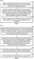
FIG. 5 is a flow diagram depicting an example of a method for detecting a degraded component of an engineered system. - While the disclosure is susceptible to various modifications and alternative forms, specific examples have been in the drawings and will be described in detail herein. However, it should be understood that the disclosure is not intended to be limited to the particular forms disclosed. Rather, the intention is to cover all modifications, equivalents and alternatives falling within the scope of the disclosure.
- Referring to
FIG. 1 , an example of asystem 100 for training apredictive model 138 for sensing degraded components in an engineeredsystem 112 is depicted. The engineeredsystem 112 includes a set ofcomponents 114 having afirst component 116, asecond component 118, and athird component 120. While three components are depicted for illustrative purposes, it should be understood that in practice, the set ofcomponents 114 may include more or fewer than three. In most practical application, the set ofcomponents 114 may include numerous components. - The engineered
system 112 may correspond to a vehicle, such as an aircraft. For example,FIG. 1 depicts a fleet ofaircraft 122 including afirst aircraft 122A, asecond aircraft 122B, and athird aircraft 122C. Each of theaircraft 122A-C may be of the same type and include the same components as each other. As such, each of theaircraft 122A-C may correspond to the engineeredsystem 112. - To illustrate, the
first aircraft 122A may include afirst component 116A that corresponds to thefirst component 116, asecond component 118A that correspond to thesecond component 118, and a third component 120Athat corresponds to thethird component 120. Likewise, thesecond aircraft 122B may include afirst component 116B that corresponds to both thefirst component 116A and thefirst component 116, asecond component 118B that correspond to both thesecond component 118A and thesecond component 118, and athird component 120B that corresponds to both thethird component 120A and thethird component 120. Finally, thethird aircraft 122C may include: afirst component 116C that corresponds to thefirst component 116A, thefirst component 116B, and thefirst component 116; asecond component 118C that correspond to thesecond component 118A, thesecond component 118B, and thesecond component 118; and athird component 120C that corresponds to thethird component 120A, thethird component 120B, and thethird component 120. - Each of the
components components 114 may include a set of user input devices (e.g., flight controls, user prompts, audio and video recordings, etc.), a set of machines (e.g., control surfaces, engine systems, motors, etc.), a set of measurement sensors (e.g., pressure sensors, temperature sensors, etc.), or combinations thereof. When produced in large quantities, the data produced by the set ofcomponents 114 may be used astraining data 102. - The
training data 102 represents a set ofoperational behaviors 104 associated respectively with the set ofcomponents 114 that make up the engineeredsystem 112. For example, thetraining data 102 may represent a firstoperational behavior 106 associated with thefirst component 116, a secondoperational behavior 108 associated with thesecond component 118, and a thirdoperational behavior 110 associated with thethird component 120. Because thetraining data 102 is continuously collected during normal operation of the engineeredsystem 112, the set ofoperational behaviors 104 may include, with few exceptions, nominal behaviors suitable for training thepredictive model 138. It should be noted that some off-nominal data in the training data stream is expected. However, given the large amounts of data received, the off-nominal data may not rise to a level of significance. Thus, the disclosedsystem 100 may be a robust solution capable of accepting training data with such "noise." Further, because thetraining data 102 may be collected over the fleet ofaircraft 122, the set ofoperational behaviors 104 may describe nominal behaviors in the context of the fleet ofaircraft 122 as opposed to any individual aircraft of the fleet ofaircraft 122. - The
system 100 may include acomputing device 130 configured to train thepredictive model 138. Thecomputing device 130 may include aprocessor 132 and amemory 134. Theprocessor 132 may include a central processing unit (CPU), a graphical processing unit (GPU), a digital signal processor (DSP), a peripheral interface controller (PIC), or another type of microprocessor. It may be implemented as an integrated circuit, a field programmable gate array (FPGA), an application specific integrated circuit (ASIC), a combination of logic gate circuitry, other types of digital or analog electrical design components, or the like, or combinations thereof. In some examples, theprocessor 132 may be distributed across multiple processing elements, relying on distributive processing operations. - Further, the
computing device 130 may includememory 134 such as random-access memory (RAM), read-only memory (ROM), magnetic disk memory, optical disk memory, flash memory, another type of memory capable of storing data and processor instructions, or the like, or combinations thereof. In some examples, the memory, or portions thereof, may be located externally or remotely from the rest of thecomputing device 130. Thememory 134 may store instructions that, when executed by theprocessor 132, cause theprocessor 132 to perform operations. The operations may correspond to any operations described herein. In particular, the operations may correspond to training thepredictive model 138. - The
processor 132 and thememory 134 may be used together to implement a supervisedmachine learning process 136 to generate thepredictive model 138. Thepredictive model 138 may include any artificial intelligence model usable to categorize operational behaviors as normal or anomalous. For example, thepredictive model 138 may include decision trees, association rules, other types of machine learning classification processes, or combinations thereof. It may be implemented as support vector machine networks, Bayesian networks, neural networks, other types of machine learning classification network systems, or combinations thereof. - During operation, the
training data 102 may be received from multiple system implementations. For illustration purposes,FIG. 1 depicts thetraining data 102 as being received from the fleet ofaircraft 122, or from anysingle aircraft aircraft 122, depending on whether the engineeredsystem 112 is to be analyzed at a fleet level or at an individual aircraft level. AlthoughFIG. 1 depicts aircraft, it should be understood that the engineered system may correspond to any type of mechanical or electrical system, and not just aircraft. Thepredictive model 138 may then be trained through the supervisedmachine learning process 136 using thetraining data 102. Because the set ofoperational behaviors 104 may include, for the most part, nominal behaviors of the set ofcomponents 114, thepredictive model 138 is configured to distinguish between normal operational behaviors and anomalous operational behaviors for thefirst component 116. Beneficially, the predictions may be based not only on the firstoperational behavior 106 associated with thefirst component 116, but also on the otheroperational behaviors component 116, but which may be relevant as thesecond component 118 andthird component 120 interact with thefirst component 116 within the engineeredsystem 112. In a like manner, a secondpredictive model 139 is generated to distinguish between normal and anomalous operational behaviors of thesecond component 118, and a thirdpredictive model 140 may be generated to distinguish between normal and anomalous operational behaviors of thethird component 120. - By training the
predictive model 138 based on thetraining data 102 that represents otheroperational behaviors other components operational behavior 106 of thefirst component 116, thepredictive model 138 may be configured to take into account the engineeredsystem 122 as a whole in determining whether thefirst component 116 is operating in a normal or anomalous way. Similar benefits exist for the secondpredictive model 139 and the thirdpredictive model 140. Other advantages may exist. - Referring to
FIG. 2 , an example of asystem 200 for using apredictive model 138 to predict a first normaloperational behavior 202 associated with acomponent 116 of an engineeredsystem 112 is depicted. Once thepredictive model 138 is trained, as described with reference toFIG. 1 , it is used to predict the first normaloperational behavior 202 of thefirst component 116. For example, a secondnormal operating behavior 204 of thesecond component 118 and a third normaloperational behavior 206 of thethird component 120 may be input into thepredictive model 138. Based on the secondnormal operating behavior 204 and the third normaloperational behavior 206, thepredictive model 138 may determine or predict the first normaloperational behavior 202 of thefirst component 116. As explained further with respect toFIG. 3 , the predicted first normaloperational behavior 202 may be compared to an actual behavior of thecomponent 116 to determine whether thecomponent 116 is behaving normally or anomalously. AlthoughFIG. 2 is directed to predicting the first normaloperational behavior 202 of thefirst component 116, the secondpredictive model 139 may be used in a similar fashion to predict the second normaloperational behavior 204 of thesecond component 118 based on the first normaloperational behavior 202 and the third normaloperational behavior 206, and the thirdpredictive model 140 may be used in a similar fashion to predict the third normaloperational behavior 206 of thethird component 120 based on the first normaloperational behavior 202 and the second normaloperational behavior 204. - Referring to
FIG. 3 , an example of asystem 300 for detecting a degraded component of an engineeredsystem 112 is depicted. Thesystem 300 may include the engineeredsystem 112 with the set ofcomponents 114 and acomputing device 322. In the case where the engineeredsystem 112 is an aircraft, thecomputing device 322 may be positioned within anavionics bay 320 of the aircraft. Alternatively, thecomputing device 322 may be ground-based and may be used for post-flight processing. - The
computing device 322 may include aprocessor 324, amemory 326, and anoutput device 328. Theprocessor 324 may include a central processing unit (CPU), a graphical processing unit (GPU), a digital signal processor (DSP), a peripheral interface controller (PIC), or another type of microprocessor. It may be implemented as an integrated circuit, a field programmable gate array (FPGA), an application specific integrated circuit (ASIC), a combination of logic gate circuitry, other types of digital or analog electrical design components, or the like, or combinations thereof. In some examples, theprocessor 324 may be distributed across multiple processing elements, relying on distributive processing operations. - The
memory 326 may include random-access memory (RAM), read-only memory (ROM), magnetic disk memory, optical disk memory, flash memory, another type of memory capable of storing data and processor instructions, or the like, or combinations thereof. In some examples, thememory 326, or portions thereof, may be located externally or remotely from the rest of thecomputing device 322. Thememory 326 may store instructions that, when executed by theprocessor 324, cause theprocessor 324 to perform operations. The operations may correspond to any operations described herein. In particular, the operations may correspond to using thepredictive model 138 for detecting a fault with one of thecomponents - The
output device 328 may include any device capable of communicating with users or devices external to thecomputing device 322. For example, theoutput device 328 may include a user output device, such as an indicator light, a display screen, a speaker, etc. Theoutput device 328 may also include a network output device, such as a serial communication device, a network card, etc. - The
predictive models computing device 322, either at thememory 326 or in another form. Based on outcomes of using thepredictive models output device 328 is configured to communicate the indication offault diagnosis 330 to a user or to another device. - During operation, the engineered
system 112 generates real-time data 310 including a set of real-timeoperational behaviors 308. As used herein, the term "real-time" means that the real-time data 310 corresponds to a currently occurring operation (such as a flight that is currently occurring) or to a most recent operation (such as the most recent flight taken by an aircraft). In particular, the concept of "real-time" is intended to take into account delays with accessing data. The set of real-timeoperational behaviors 308 may include a first real-time operational behavior associated with thefirst component 116, a second real-time operational behavior associated with thesecond component 118, and a third real-time operational behavior associated with thethird component 120. - The
computing device 322 receives real-time data 310. Based on the real-time data 310, theprocessor 324 categorizes the first real-timeoperational behavior 302 associated with thecomponent 116 as normal or anomalous based on thepredictive model 138. For example, thepredictive model 138 may calculate anormal operating behavior 202 for thefirst component 116. The firstnormal operating behavior 202 may be compared to the first real-timeoperational behavior 302 to determine whether the first real-timeoperational behavior 302 is anomalous. In response to categorizing the first real-timeoperational behavior 302 as anomalous, theprocessor 324 generates the indication offault diagnosis 330. In some examples, the categorization of the first real-timeoperational behavior 302 may occur during a flight. - Similar calculations are made to determine whether the second real-time
operational behavior 304 and/or the third real-timeoperational behavior 306 are anomalous. For example, the secondpredictive model 139 may calculate a second normaloperational behavior 204 associated with thesecond component 118 and the thirdpredictive model 140 may calculate a thirdnormal operating behavior 206 associated with thethird component 120. Thus, for each of thecomponents operational behaviors operational behaviors 308. If any operational behavior of the set of real-timeoperational behaviors 308 is anomalous, then the indication offault diagnosis 330 is generated, indicating which of thecomponents - By using the predictive models 138-140 that classify the real-
time data 310 based on the real-timeoperational behaviors components system 300 may detect degraded components and/or subsystems in the context of the entire engineered system, as opposed to a behavior of a single component. As such, thesystem 300 may detect anomalous behavior that other detection systems may miss. Other benefits may exist. - Referring to
FIG. 4 , an example of amethod 400 for training a predictive model is depicted. Themethod 400 includes receiving training data representing a set of operational behaviors associated respectively with a set of components that make up an engineered system, at 402. For example, thetraining data 102 may be received at thecomputing device 130. - The
method 400 further includes generating a predictive model, based on the training data, configured to predict a normal operational behavior associated with a component of the set of components relative to other normal operational behaviors associated respectively with other components of the set of components, at 404. For example, thepredictive models components system 112 as a whole in order to diagnose degradation within the engineeredsystem 112, which may be related to components other than those modeled by thepredictive models method 400 also includes analyzing a pattern based on the first predictive model and the second predictive model to enable identification of the component, at 406. By analyzing patterns associated with which of thepredictive models - Thus, by generating a predictive model configured to predict a normal operational behavior associated with a component relative to other normal operational behaviors associated respectively with other components of an engineered system, the
method 400 may take into account an engineered system as a whole in determining whether operation of a component is normal or anomalous. Other advantages may exist. - Referring to
FIG. 5 , an example of amethod 500 for detecting a degraded component of an engineered system is depicted. Themethod 500 includes receiving real-time data representing a set of real-time operational behaviors associated respectively with a set of components that make up an engineered system, the set of real-time operational behaviors including a real-time operational behavior associated with a component of the set of components, at 502. For example, the real-time data 310 may be received by thecomputing device 322. - The
method 500 further includes categorizing the real-time operational behavior associated with the component as normal or anomalous based on a predictive model configured to predict a normal operational behavior associated with the component relative to other normal operational behaviors associated respectively with other components of the set of components, at 504. For example, the first real-timeoperational behavior 302 may be categorized by thepredictive model 138. - The
method 500 also includes, in response to categorizing the real-time operational behavior as anomalous, generating an indication of fault diagnosis, at 506. Theprocessor 324 generates the indication offault diagnosis 330. - The
method 500 may include sending the indication of fault diagnosis to an output device, at 508. For example, the indication offault diagnosis 330 may be sent to theoutput device 328 for output. - By categorizing the real-time operational behavior associated with the component as normal or anomalous based on a predictive model configured to predict a normal operational behavior associated with the component relative to other normal operational behaviors associated respectively with other components of the set of components, the
method 400 may detect degraded components and/or subsystems in the context of the entire engineered system, as opposed to a behavior of a single component. Other benefits may exist.
Claims (15)
- A method comprising:receiving (402) training data (102) representing a set of operational behaviors (104) associated respectively with a set of components (114) that make up an engineered system (112);generating (404) a predictive model (138), based on the training data (102), configured to predict a normal operational behavior (202) associated with a component (116) of the set of components (114) relative to other normal operational behaviors (204, 206) associated respectively with other components (118, 120) of the set of components (114);receiving (502) real-time data (310) representing a set of real-time operational behaviors (308) associated respectively with the set of components (114), the set of real-time operational behaviors (308) including a real-time operational behavior (302) associated with the component (116);categorizing (504) the real-time operational behavior (302) associated with the component (116) as normal or anomalous based on the predictive model ( 138); andin response to categorizing the real-time operational behavior (302) as anomalous, generating (506) an indication of fault diagnosis (330);the method further comprising:generating a second predictive model (139), based on the training data (102), configured to predict a second normal operational behavior (204) associated with a second component (118) of the set of components (114) relative to the other operational behaviors (202, 206) associated respectively with the other components (116, 120) of the set of components (114), wherein the set of real-time operational behaviors (308) includes a second real-time operational behavior (304) of the second component (118);categorizing the second real-time operational behavior (304) associated with the second component (118) as normal or anomalous; andin response to categorizing the second real-time operational behavior (304) as anomalous, generating the indication of fault diagnosis (330),wherein the set of components (114) includes a set of measurement sensors; andwhereby the method further comprises analyzing a pattern based on the first predictive model and the second predictive model to enable identification of the component, wherein the indication of fault diagnosis identifies the component.
- The method of claim 1, wherein the set of components includes vehicle components (116A-C, 118A-C, 120A-C), and wherein the engineered system is a vehicle (122A-C).
- The method of any of claims 1-2, wherein the set of components includes aircraft components (116A-C, 118A-C, 120A-C), and wherein the engineered system is an aircraft (122A-C).
- The method of any of claims 1-3, wherein the training data is received from multiple aircraft (122A, 122B, 122C) of a fleet of aircraft (122).
- The method of any of claims 3-4, wherein categorizing the real-time operational behavior (302) associated with the component (116) is performed at a processor (324) within an avionics bay (320) of the aircraft (122A-C) while the aircraft (122A-C) is in flight.
- The method of any of claims 1-5, wherein generating the predictive model (138) comprises training the predictive model (138) through a supervised machine learning process (136) using the training data (102).
- The method of any of claims 1-6, wherein the set of operational behaviors (104) of the training data (102) include both nominal and off-nominal operational behaviors.
- The method of any of claims 1-7, wherein the set of real-time operational behaviors (308) includes sets of user inputs, sets of machine states, sets of measurements, or combinations thereof.
- The method of any of claims 1-8, further comprising:
sending (508) the indication of fault diagnosis (330) to an output device (328). - A system (300) comprising:a set of components (114) that make up an engineered system (112) configured to generate real-time data (310) representing a set of real-time operational behaviors (308) associated respectively with the set of components (114), wherein the set of components (114) includes a set of measurement sensors;a computer implemented predictive model (138) and a second predictive model configured to predict a normal operational behavior (202) associated with a component (116), respectively second component, of the set of components (114) relative to other normal operational behaviors (204, 206) associated respectively with other components (118, 112) of the set of components (114);a processor (324) configured to receive the set of real-time operational behaviors (308), the set of real-time operational behaviors (308) including a real-time operational behavior (302) associated with the component (116) and with the second component, and to categorize the real-time operational behavior (302) associated with the component (116) and with the second component as normal or anomalous based on the predictive model (138), the processor being further configured to analyze a pattern based on the computer implemented predictive model and the second predictive model to enable identification of the component; andan output device (328) configured to output an indication of fault diagnosis (330) in response to the processor (324) categorizing the real-time operation behavior (302) as anomalous, wherein the indication of fault diagnosis identifies the component.
- The system of claim 10, further comprising:
a second processor (132) configured to receive training data (102) representing a set of operational behaviors (106, 108, 110) associated respectively with the set of components (116, 118, 120) and to generate the predictive model (138) based on the training data (102). - The system of claim 11, whereby the processor and the second processors are configured to operate according to any one of method claims 1 to 9.
- The system of any of claims 10 to 12, whereby the set of measurement sensors comprises a pressure sensor.
- The system of any of claims 10 to 13, whereby the set of measurement sensors comprises a temperature sensor.
- A memory (134) capable of storing data and processor instructions, the memory storing instructions that, when executed by a processor (132), cause the processor to perform operations according to the method of any of claims 1 to 9.
Applications Claiming Priority (1)
| Application Number | Priority Date | Filing Date | Title |
|---|---|---|---|
| US16/433,822 US20200385141A1 (en) | 2019-06-06 | 2019-06-06 | Data driven machine learning for modeling aircraft sensors |
Publications (2)
| Publication Number | Publication Date |
|---|---|
| EP3748450A1 EP3748450A1 (en) | 2020-12-09 |
| EP3748450B1 true EP3748450B1 (en) | 2024-07-03 |
Family
ID=70482283
Family Applications (1)
| Application Number | Title | Priority Date | Filing Date |
|---|---|---|---|
| EP20172243.6A Active EP3748450B1 (en) | 2019-06-06 | 2020-04-30 | Data driven machine learning for modeling aircraft sensors |
Country Status (7)
| Country | Link |
|---|---|
| US (1) | US20200385141A1 (en) |
| EP (1) | EP3748450B1 (en) |
| JP (1) | JP7582794B2 (en) |
| KR (1) | KR102935380B1 (en) |
| CN (1) | CN112052714B (en) |
| AU (1) | AU2020202134B2 (en) |
| BR (1) | BR102020007655A2 (en) |
Families Citing this family (5)
| Publication number | Priority date | Publication date | Assignee | Title |
|---|---|---|---|---|
| KR102597598B1 (en) * | 2022-01-20 | 2023-11-01 | 아주대학교산학협력단 | Real-time fault diagnosis method of unmanned aerial vehicle using artificial intelligence algorithm |
| EP4336295A1 (en) * | 2022-09-08 | 2024-03-13 | Hosea Precision Co., Ltd. | System and method for intelligently monitoring machine equipment |
| KR102736683B1 (en) * | 2023-11-01 | 2024-12-02 | 한화시스템 주식회사 | Aircraft health management method and aircraft health management pparatus |
| KR102730084B1 (en) * | 2023-11-22 | 2024-11-14 | 한화시스템 주식회사 | Aircraft health management apparatus and the method thereof |
| KR20250094759A (en) * | 2023-12-18 | 2025-06-26 | 포스코홀딩스 주식회사 | Drone and Method for controlling Drone |
Family Cites Families (16)
| Publication number | Priority date | Publication date | Assignee | Title |
|---|---|---|---|---|
| US8165826B2 (en) * | 2008-09-30 | 2012-04-24 | The Boeing Company | Data driven method and system for predicting operational states of mechanical systems |
| US9569959B1 (en) * | 2012-10-02 | 2017-02-14 | Rockwell Collins, Inc. | Predictive analysis for threat detection |
| US9694903B2 (en) * | 2013-06-27 | 2017-07-04 | Airbus Operations (Sas) | Secure aircraft-based mobile device connectivity systems and methods |
| EP3098681B1 (en) * | 2015-05-27 | 2020-08-26 | Tata Consultancy Services Limited | Artificial intelligence based health management of host system |
| US10926874B2 (en) * | 2016-01-15 | 2021-02-23 | Aurora Flight Sciences Corporation | Hybrid propulsion vertical take-off and landing aircraft |
| US20170331844A1 (en) * | 2016-05-13 | 2017-11-16 | Sikorsky Aircraft Corporation | Systems and methods for assessing airframe health |
| FR3052273B1 (en) * | 2016-06-02 | 2018-07-06 | Airbus | PREDICTION OF TROUBLES IN AN AIRCRAFT |
| US10474789B2 (en) * | 2016-06-24 | 2019-11-12 | The Boeing Company | Prediction methods and systems for structural repair during heavy maintenance of aircraft |
| US10474932B2 (en) * | 2016-09-01 | 2019-11-12 | Uptake Technologies, Inc. | Detection of anomalies in multivariate data |
| US10472096B2 (en) * | 2017-05-30 | 2019-11-12 | The Boeing Company | Advanced analytic methods and systems utilizing trust-weighted machine learning models |
| US10643187B2 (en) * | 2017-06-09 | 2020-05-05 | Kidde Technologies, Inc. | Reporting and prioritizing faults for aircraft downtime reduction |
| US10969775B2 (en) * | 2017-06-23 | 2021-04-06 | Johnson Controls Technology Company | Predictive diagnostics system with fault detector for preventative maintenance of connected equipment |
| JP6243080B1 (en) * | 2017-08-03 | 2017-12-06 | 株式会社日立パワーソリューションズ | Preprocessor and abnormal sign diagnosis system |
| US10672204B2 (en) * | 2017-11-15 | 2020-06-02 | The Boeing Company | Real time streaming analytics for flight data processing |
| CN108491860B (en) * | 2018-02-24 | 2021-02-05 | 中国石油大学(北京) | Shale gas fracturing equipment full life cycle real-time reliability dynamic evaluation method and device |
| CN109492193B (en) * | 2018-12-28 | 2020-11-27 | 同济大学 | Anomaly network data generation and prediction method based on deep machine learning model |
-
2019
- 2019-06-06 US US16/433,822 patent/US20200385141A1/en not_active Abandoned
-
2020
- 2020-03-25 AU AU2020202134A patent/AU2020202134B2/en active Active
- 2020-04-16 BR BR102020007655-8A patent/BR102020007655A2/en unknown
- 2020-04-30 EP EP20172243.6A patent/EP3748450B1/en active Active
- 2020-05-08 CN CN202010381502.9A patent/CN112052714B/en active Active
- 2020-05-14 KR KR1020200057940A patent/KR102935380B1/en active Active
- 2020-05-27 JP JP2020092347A patent/JP7582794B2/en active Active
Also Published As
| Publication number | Publication date |
|---|---|
| JP7582794B2 (en) | 2024-11-13 |
| BR102020007655A2 (en) | 2020-12-08 |
| CN112052714A (en) | 2020-12-08 |
| AU2020202134B2 (en) | 2025-08-14 |
| KR20200140999A (en) | 2020-12-17 |
| AU2020202134A1 (en) | 2020-12-24 |
| KR102935380B1 (en) | 2026-03-06 |
| JP2021005370A (en) | 2021-01-14 |
| US20200385141A1 (en) | 2020-12-10 |
| EP3748450A1 (en) | 2020-12-09 |
| CN112052714B (en) | 2025-03-07 |
Similar Documents
| Publication | Publication Date | Title |
|---|---|---|
| KR102935380B1 (en) | Data driven machine learning for modeling aircraft sensors | |
| US20210147182A1 (en) | Non-intrusive data analytics system for adaptive intelligent condition monitoring of lifts | |
| US20200371858A1 (en) | Fault Predicting System and Fault Prediction Method | |
| KR20210097369A (en) | Progonstics system of machine equipment using big data based on potential failure mode analysis and method thereof | |
| US20170293862A1 (en) | Machine learning device and machine learning method for learning fault prediction of main shaft or motor which drives main shaft, and fault prediction device and fault prediction system including machine learning device | |
| CN113962299A (en) | Intelligent operation monitoring and fault diagnosis general model for nuclear power equipment | |
| JP2009053938A (en) | Equipment diagnosis system and equipment diagnosis method based on multiple models | |
| KR20190021560A (en) | Failure prediction system using big data and failure prediction method | |
| EP3413246A1 (en) | Reporting and prioritizing faults for aircraft downtime reduction | |
| CN109791401A (en) | Generate the fault model for being used for embedded analysis and diagnosis/Forecast reasoning | |
| KR102917255B1 (en) | Ai-based automatic equipment failure prediction digital twin system | |
| WO2017153005A1 (en) | Smart embedded control system for a field device of an automation system | |
| CN119902559B (en) | Real-time defect prediction system and method for data-driven unmanned aerial vehicle flight control system | |
| JP4635194B2 (en) | Anomaly detection device | |
| KR20220032822A (en) | Method for estimating condition of elevator | |
| Medjaher et al. | Failure prognostic by using dynamic Bayesian networks | |
| KR102483210B1 (en) | Facility health index derivation system and facility health index derivation method by predicting the probability of manufacturing facility abnormality using xai | |
| KR102388973B1 (en) | Main distrubution frame having earthquake-resistant facilities | |
| KR102695494B1 (en) | Smart factory equipment preventive maintenance system and method with enhanced security | |
| US20180059639A1 (en) | Cell control system | |
| EP3995920B1 (en) | EVENT ANALYSIS IN MODULAR INDUSTRIAL PLANTS | |
| KR102301011B1 (en) | System for failure prediction of elevator door | |
| KR102533298B1 (en) | Apparatus for evaluating fault diagnosis model based on system availability and method thereof | |
| KR102733034B1 (en) | Post-processing method based on artificial intelligence for improving performance of network device fault detector and appratus thereof | |
| KR20240116524A (en) | Identification of error sources at the command level of the process |
Legal Events
| Date | Code | Title | Description |
|---|---|---|---|
| PUAI | Public reference made under article 153(3) epc to a published international application that has entered the european phase |
Free format text: ORIGINAL CODE: 0009012 |
|
| STAA | Information on the status of an ep patent application or granted ep patent |
Free format text: STATUS: THE APPLICATION HAS BEEN PUBLISHED |
|
| AK | Designated contracting states |
Kind code of ref document: A1 Designated state(s): AL AT BE BG CH CY CZ DE DK EE ES FI FR GB GR HR HU IE IS IT LI LT LU LV MC MK MT NL NO PL PT RO RS SE SI SK SM TR |
|
| AX | Request for extension of the european patent |
Extension state: BA ME |
|
| STAA | Information on the status of an ep patent application or granted ep patent |
Free format text: STATUS: REQUEST FOR EXAMINATION WAS MADE |
|
| 17P | Request for examination filed |
Effective date: 20210602 |
|
| RBV | Designated contracting states (corrected) |
Designated state(s): AL AT BE BG CH CY CZ DE DK EE ES FI FR GB GR HR HU IE IS IT LI LT LU LV MC MK MT NL NO PL PT RO RS SE SI SK SM TR |
|
| STAA | Information on the status of an ep patent application or granted ep patent |
Free format text: STATUS: EXAMINATION IS IN PROGRESS |
|
| 17Q | First examination report despatched |
Effective date: 20220701 |
|
| RAP3 | Party data changed (applicant data changed or rights of an application transferred) |
Owner name: THE BOEING COMPANY |
|
| GRAP | Despatch of communication of intention to grant a patent |
Free format text: ORIGINAL CODE: EPIDOSNIGR1 |
|
| STAA | Information on the status of an ep patent application or granted ep patent |
Free format text: STATUS: GRANT OF PATENT IS INTENDED |
|
| INTG | Intention to grant announced |
Effective date: 20231011 |
|
| GRAJ | Information related to disapproval of communication of intention to grant by the applicant or resumption of examination proceedings by the epo deleted |
Free format text: ORIGINAL CODE: EPIDOSDIGR1 |
|
| STAA | Information on the status of an ep patent application or granted ep patent |
Free format text: STATUS: EXAMINATION IS IN PROGRESS |
|
| GRAP | Despatch of communication of intention to grant a patent |
Free format text: ORIGINAL CODE: EPIDOSNIGR1 |
|
| STAA | Information on the status of an ep patent application or granted ep patent |
Free format text: STATUS: GRANT OF PATENT IS INTENDED |
|
| INTC | Intention to grant announced (deleted) | ||
| INTG | Intention to grant announced |
Effective date: 20240206 |
|
| GRAS | Grant fee paid |
Free format text: ORIGINAL CODE: EPIDOSNIGR3 |
|
| GRAA | (expected) grant |
Free format text: ORIGINAL CODE: 0009210 |
|
| STAA | Information on the status of an ep patent application or granted ep patent |
Free format text: STATUS: THE PATENT HAS BEEN GRANTED |
|
| AK | Designated contracting states |
Kind code of ref document: B1 Designated state(s): AL AT BE BG CH CY CZ DE DK EE ES FI FR GB GR HR HU IE IS IT LI LT LU LV MC MK MT NL NO PL PT RO RS SE SI SK SM TR |
|
| P01 | Opt-out of the competence of the unified patent court (upc) registered |
Effective date: 20240528 |
|
| REG | Reference to a national code |
Ref country code: CH Ref legal event code: EP |
|
| REG | Reference to a national code |
Ref country code: DE Ref legal event code: R096 Ref document number: 602020033180 Country of ref document: DE |
|
| REG | Reference to a national code |
Ref country code: LT Ref legal event code: MG9D |
|
| REG | Reference to a national code |
Ref country code: NL Ref legal event code: MP Effective date: 20240703 |
|
| PG25 | Lapsed in a contracting state [announced via postgrant information from national office to epo] |
Ref country code: PT Free format text: LAPSE BECAUSE OF FAILURE TO SUBMIT A TRANSLATION OF THE DESCRIPTION OR TO PAY THE FEE WITHIN THE PRESCRIBED TIME-LIMIT Effective date: 20241104 |
|
| REG | Reference to a national code |
Ref country code: AT Ref legal event code: MK05 Ref document number: 1700471 Country of ref document: AT Kind code of ref document: T Effective date: 20240703 |
|
| PG25 | Lapsed in a contracting state [announced via postgrant information from national office to epo] |
Ref country code: NL Free format text: LAPSE BECAUSE OF FAILURE TO SUBMIT A TRANSLATION OF THE DESCRIPTION OR TO PAY THE FEE WITHIN THE PRESCRIBED TIME-LIMIT Effective date: 20240703 |
|
| PG25 | Lapsed in a contracting state [announced via postgrant information from national office to epo] |
Ref country code: PT Free format text: LAPSE BECAUSE OF FAILURE TO SUBMIT A TRANSLATION OF THE DESCRIPTION OR TO PAY THE FEE WITHIN THE PRESCRIBED TIME-LIMIT Effective date: 20241104 Ref country code: NL Free format text: LAPSE BECAUSE OF FAILURE TO SUBMIT A TRANSLATION OF THE DESCRIPTION OR TO PAY THE FEE WITHIN THE PRESCRIBED TIME-LIMIT Effective date: 20240703 |
|
| PG25 | Lapsed in a contracting state [announced via postgrant information from national office to epo] |
Ref country code: NO Free format text: LAPSE BECAUSE OF FAILURE TO SUBMIT A TRANSLATION OF THE DESCRIPTION OR TO PAY THE FEE WITHIN THE PRESCRIBED TIME-LIMIT Effective date: 20241003 |
|
| PG25 | Lapsed in a contracting state [announced via postgrant information from national office to epo] |
Ref country code: FI Free format text: LAPSE BECAUSE OF FAILURE TO SUBMIT A TRANSLATION OF THE DESCRIPTION OR TO PAY THE FEE WITHIN THE PRESCRIBED TIME-LIMIT Effective date: 20240703 Ref country code: GR Free format text: LAPSE BECAUSE OF FAILURE TO SUBMIT A TRANSLATION OF THE DESCRIPTION OR TO PAY THE FEE WITHIN THE PRESCRIBED TIME-LIMIT Effective date: 20241004 Ref country code: PL Free format text: LAPSE BECAUSE OF FAILURE TO SUBMIT A TRANSLATION OF THE DESCRIPTION OR TO PAY THE FEE WITHIN THE PRESCRIBED TIME-LIMIT Effective date: 20240703 |
|
| PG25 | Lapsed in a contracting state [announced via postgrant information from national office to epo] |
Ref country code: BG Free format text: LAPSE BECAUSE OF FAILURE TO SUBMIT A TRANSLATION OF THE DESCRIPTION OR TO PAY THE FEE WITHIN THE PRESCRIBED TIME-LIMIT Effective date: 20240703 |
|
| PG25 | Lapsed in a contracting state [announced via postgrant information from national office to epo] |
Ref country code: LV Free format text: LAPSE BECAUSE OF FAILURE TO SUBMIT A TRANSLATION OF THE DESCRIPTION OR TO PAY THE FEE WITHIN THE PRESCRIBED TIME-LIMIT Effective date: 20240703 |
|
| PG25 | Lapsed in a contracting state [announced via postgrant information from national office to epo] |
Ref country code: IS Free format text: LAPSE BECAUSE OF FAILURE TO SUBMIT A TRANSLATION OF THE DESCRIPTION OR TO PAY THE FEE WITHIN THE PRESCRIBED TIME-LIMIT Effective date: 20241103 Ref country code: AT Free format text: LAPSE BECAUSE OF FAILURE TO SUBMIT A TRANSLATION OF THE DESCRIPTION OR TO PAY THE FEE WITHIN THE PRESCRIBED TIME-LIMIT Effective date: 20240703 |
|
| PG25 | Lapsed in a contracting state [announced via postgrant information from national office to epo] |
Ref country code: HR Free format text: LAPSE BECAUSE OF FAILURE TO SUBMIT A TRANSLATION OF THE DESCRIPTION OR TO PAY THE FEE WITHIN THE PRESCRIBED TIME-LIMIT Effective date: 20240703 Ref country code: CZ Free format text: LAPSE BECAUSE OF FAILURE TO SUBMIT A TRANSLATION OF THE DESCRIPTION OR TO PAY THE FEE WITHIN THE PRESCRIBED TIME-LIMIT Effective date: 20240703 |
|
| PG25 | Lapsed in a contracting state [announced via postgrant information from national office to epo] |
Ref country code: RS Free format text: LAPSE BECAUSE OF FAILURE TO SUBMIT A TRANSLATION OF THE DESCRIPTION OR TO PAY THE FEE WITHIN THE PRESCRIBED TIME-LIMIT Effective date: 20241003 Ref country code: ES Free format text: LAPSE BECAUSE OF FAILURE TO SUBMIT A TRANSLATION OF THE DESCRIPTION OR TO PAY THE FEE WITHIN THE PRESCRIBED TIME-LIMIT Effective date: 20240703 |
|
| PG25 | Lapsed in a contracting state [announced via postgrant information from national office to epo] |
Ref country code: RS Free format text: LAPSE BECAUSE OF FAILURE TO SUBMIT A TRANSLATION OF THE DESCRIPTION OR TO PAY THE FEE WITHIN THE PRESCRIBED TIME-LIMIT Effective date: 20241003 Ref country code: PL Free format text: LAPSE BECAUSE OF FAILURE TO SUBMIT A TRANSLATION OF THE DESCRIPTION OR TO PAY THE FEE WITHIN THE PRESCRIBED TIME-LIMIT Effective date: 20240703 Ref country code: NO Free format text: LAPSE BECAUSE OF FAILURE TO SUBMIT A TRANSLATION OF THE DESCRIPTION OR TO PAY THE FEE WITHIN THE PRESCRIBED TIME-LIMIT Effective date: 20241003 Ref country code: LV Free format text: LAPSE BECAUSE OF FAILURE TO SUBMIT A TRANSLATION OF THE DESCRIPTION OR TO PAY THE FEE WITHIN THE PRESCRIBED TIME-LIMIT Effective date: 20240703 Ref country code: IS Free format text: LAPSE BECAUSE OF FAILURE TO SUBMIT A TRANSLATION OF THE DESCRIPTION OR TO PAY THE FEE WITHIN THE PRESCRIBED TIME-LIMIT Effective date: 20241103 Ref country code: HR Free format text: LAPSE BECAUSE OF FAILURE TO SUBMIT A TRANSLATION OF THE DESCRIPTION OR TO PAY THE FEE WITHIN THE PRESCRIBED TIME-LIMIT Effective date: 20240703 Ref country code: GR Free format text: LAPSE BECAUSE OF FAILURE TO SUBMIT A TRANSLATION OF THE DESCRIPTION OR TO PAY THE FEE WITHIN THE PRESCRIBED TIME-LIMIT Effective date: 20241004 Ref country code: FI Free format text: LAPSE BECAUSE OF FAILURE TO SUBMIT A TRANSLATION OF THE DESCRIPTION OR TO PAY THE FEE WITHIN THE PRESCRIBED TIME-LIMIT Effective date: 20240703 Ref country code: ES Free format text: LAPSE BECAUSE OF FAILURE TO SUBMIT A TRANSLATION OF THE DESCRIPTION OR TO PAY THE FEE WITHIN THE PRESCRIBED TIME-LIMIT Effective date: 20240703 Ref country code: CZ Free format text: LAPSE BECAUSE OF FAILURE TO SUBMIT A TRANSLATION OF THE DESCRIPTION OR TO PAY THE FEE WITHIN THE PRESCRIBED TIME-LIMIT Effective date: 20240703 Ref country code: BG Free format text: LAPSE BECAUSE OF FAILURE TO SUBMIT A TRANSLATION OF THE DESCRIPTION OR TO PAY THE FEE WITHIN THE PRESCRIBED TIME-LIMIT Effective date: 20240703 Ref country code: AT Free format text: LAPSE BECAUSE OF FAILURE TO SUBMIT A TRANSLATION OF THE DESCRIPTION OR TO PAY THE FEE WITHIN THE PRESCRIBED TIME-LIMIT Effective date: 20240703 |
|
| REG | Reference to a national code |
Ref country code: DE Ref legal event code: R097 Ref document number: 602020033180 Country of ref document: DE |
|
| PG25 | Lapsed in a contracting state [announced via postgrant information from national office to epo] |
Ref country code: DK Free format text: LAPSE BECAUSE OF FAILURE TO SUBMIT A TRANSLATION OF THE DESCRIPTION OR TO PAY THE FEE WITHIN THE PRESCRIBED TIME-LIMIT Effective date: 20240703 Ref country code: RO Free format text: LAPSE BECAUSE OF FAILURE TO SUBMIT A TRANSLATION OF THE DESCRIPTION OR TO PAY THE FEE WITHIN THE PRESCRIBED TIME-LIMIT Effective date: 20240703 Ref country code: SM Free format text: LAPSE BECAUSE OF FAILURE TO SUBMIT A TRANSLATION OF THE DESCRIPTION OR TO PAY THE FEE WITHIN THE PRESCRIBED TIME-LIMIT Effective date: 20240703 |
|
| PG25 | Lapsed in a contracting state [announced via postgrant information from national office to epo] |
Ref country code: EE Free format text: LAPSE BECAUSE OF FAILURE TO SUBMIT A TRANSLATION OF THE DESCRIPTION OR TO PAY THE FEE WITHIN THE PRESCRIBED TIME-LIMIT Effective date: 20240703 |
|
| PG25 | Lapsed in a contracting state [announced via postgrant information from national office to epo] |
Ref country code: SK Free format text: LAPSE BECAUSE OF FAILURE TO SUBMIT A TRANSLATION OF THE DESCRIPTION OR TO PAY THE FEE WITHIN THE PRESCRIBED TIME-LIMIT Effective date: 20240703 Ref country code: IT Free format text: LAPSE BECAUSE OF FAILURE TO SUBMIT A TRANSLATION OF THE DESCRIPTION OR TO PAY THE FEE WITHIN THE PRESCRIBED TIME-LIMIT Effective date: 20240703 |
|
| PLBE | No opposition filed within time limit |
Free format text: ORIGINAL CODE: 0009261 |
|
| STAA | Information on the status of an ep patent application or granted ep patent |
Free format text: STATUS: NO OPPOSITION FILED WITHIN TIME LIMIT |
|
| 26N | No opposition filed |
Effective date: 20250404 |
|
| PGFP | Annual fee paid to national office [announced via postgrant information from national office to epo] |
Ref country code: DE Payment date: 20250429 Year of fee payment: 6 |
|
| PGFP | Annual fee paid to national office [announced via postgrant information from national office to epo] |
Ref country code: GB Payment date: 20250428 Year of fee payment: 6 |
|
| PGFP | Annual fee paid to national office [announced via postgrant information from national office to epo] |
Ref country code: FR Payment date: 20250425 Year of fee payment: 6 |
|
| PG25 | Lapsed in a contracting state [announced via postgrant information from national office to epo] |
Ref country code: SE Free format text: LAPSE BECAUSE OF FAILURE TO SUBMIT A TRANSLATION OF THE DESCRIPTION OR TO PAY THE FEE WITHIN THE PRESCRIBED TIME-LIMIT Effective date: 20240703 |
|
| REG | Reference to a national code |
Ref country code: CH Ref legal event code: H13 Free format text: ST27 STATUS EVENT CODE: U-0-0-H10-H13 (AS PROVIDED BY THE NATIONAL OFFICE) Effective date: 20251125 |
|
| PG25 | Lapsed in a contracting state [announced via postgrant information from national office to epo] |
Ref country code: LU Free format text: LAPSE BECAUSE OF NON-PAYMENT OF DUE FEES Effective date: 20250430 |
|
| PG25 | Lapsed in a contracting state [announced via postgrant information from national office to epo] |
Ref country code: MC Free format text: LAPSE BECAUSE OF FAILURE TO SUBMIT A TRANSLATION OF THE DESCRIPTION OR TO PAY THE FEE WITHIN THE PRESCRIBED TIME-LIMIT Effective date: 20240703 |
|
| REG | Reference to a national code |
Ref country code: BE Ref legal event code: MM Effective date: 20250430 |
|
| PG25 | Lapsed in a contracting state [announced via postgrant information from national office to epo] |
Ref country code: BE Free format text: LAPSE BECAUSE OF NON-PAYMENT OF DUE FEES Effective date: 20250430 |
|
| PG25 | Lapsed in a contracting state [announced via postgrant information from national office to epo] |
Ref country code: CH Free format text: LAPSE BECAUSE OF NON-PAYMENT OF DUE FEES Effective date: 20250430 |
|
| PG25 | Lapsed in a contracting state [announced via postgrant information from national office to epo] |
Ref country code: IE Free format text: LAPSE BECAUSE OF NON-PAYMENT OF DUE FEES Effective date: 20250430 |