EP3748392A1 - System and method to classify objects using radar data - Google Patents
System and method to classify objects using radar data Download PDFInfo
- Publication number
- EP3748392A1 EP3748392A1 EP19177910.7A EP19177910A EP3748392A1 EP 3748392 A1 EP3748392 A1 EP 3748392A1 EP 19177910 A EP19177910 A EP 19177910A EP 3748392 A1 EP3748392 A1 EP 3748392A1
- Authority
- EP
- European Patent Office
- Prior art keywords
- network
- output
- layers
- filter
- convolutional network
- Prior art date
- Legal status (The legal status is an assumption and is not a legal conclusion. Google has not performed a legal analysis and makes no representation as to the accuracy of the status listed.)
- Granted
Links
Images




Classifications
-
- G—PHYSICS
- G01—MEASURING; TESTING
- G01S—RADIO DIRECTION-FINDING; RADIO NAVIGATION; DETERMINING DISTANCE OR VELOCITY BY USE OF RADIO WAVES; LOCATING OR PRESENCE-DETECTING BY USE OF THE REFLECTION OR RERADIATION OF RADIO WAVES; ANALOGOUS ARRANGEMENTS USING OTHER WAVES
- G01S7/00—Details of systems according to groups G01S13/00, G01S15/00, G01S17/00
- G01S7/02—Details of systems according to groups G01S13/00, G01S15/00, G01S17/00 of systems according to group G01S13/00
- G01S7/41—Details of systems according to groups G01S13/00, G01S15/00, G01S17/00 of systems according to group G01S13/00 using analysis of echo signal for target characterisation; Target signature; Target cross-section
- G01S7/411—Identification of targets based on measurements of radar reflectivity
-
- G—PHYSICS
- G01—MEASURING; TESTING
- G01S—RADIO DIRECTION-FINDING; RADIO NAVIGATION; DETERMINING DISTANCE OR VELOCITY BY USE OF RADIO WAVES; LOCATING OR PRESENCE-DETECTING BY USE OF THE REFLECTION OR RERADIATION OF RADIO WAVES; ANALOGOUS ARRANGEMENTS USING OTHER WAVES
- G01S13/00—Systems using the reflection or reradiation of radio waves, e.g. radar systems; Analogous systems using reflection or reradiation of waves whose nature or wavelength is irrelevant or unspecified
- G01S13/88—Radar or analogous systems specially adapted for specific applications
- G01S13/93—Radar or analogous systems specially adapted for specific applications for anti-collision purposes
- G01S13/931—Radar or analogous systems specially adapted for specific applications for anti-collision purposes of land vehicles
-
- G—PHYSICS
- G01—MEASURING; TESTING
- G01S—RADIO DIRECTION-FINDING; RADIO NAVIGATION; DETERMINING DISTANCE OR VELOCITY BY USE OF RADIO WAVES; LOCATING OR PRESENCE-DETECTING BY USE OF THE REFLECTION OR RERADIATION OF RADIO WAVES; ANALOGOUS ARRANGEMENTS USING OTHER WAVES
- G01S13/00—Systems using the reflection or reradiation of radio waves, e.g. radar systems; Analogous systems using reflection or reradiation of waves whose nature or wavelength is irrelevant or unspecified
- G01S13/02—Systems using reflection of radio waves, e.g. primary radar systems; Analogous systems
- G01S13/06—Systems determining position data of a target
- G01S13/42—Simultaneous measurement of distance and other co-ordinates
-
- G—PHYSICS
- G01—MEASURING; TESTING
- G01S—RADIO DIRECTION-FINDING; RADIO NAVIGATION; DETERMINING DISTANCE OR VELOCITY BY USE OF RADIO WAVES; LOCATING OR PRESENCE-DETECTING BY USE OF THE REFLECTION OR RERADIATION OF RADIO WAVES; ANALOGOUS ARRANGEMENTS USING OTHER WAVES
- G01S13/00—Systems using the reflection or reradiation of radio waves, e.g. radar systems; Analogous systems using reflection or reradiation of waves whose nature or wavelength is irrelevant or unspecified
- G01S13/02—Systems using reflection of radio waves, e.g. primary radar systems; Analogous systems
- G01S13/50—Systems of measurement based on relative movement of target
- G01S13/52—Discriminating between fixed and moving objects or between objects moving at different speeds
- G01S13/522—Discriminating between fixed and moving objects or between objects moving at different speeds using transmissions of interrupted pulse modulated waves
- G01S13/524—Discriminating between fixed and moving objects or between objects moving at different speeds using transmissions of interrupted pulse modulated waves based upon the phase or frequency shift resulting from movement of objects, with reference to the transmitted signals, e.g. coherent MTi
- G01S13/5246—Discriminating between fixed and moving objects or between objects moving at different speeds using transmissions of interrupted pulse modulated waves based upon the phase or frequency shift resulting from movement of objects, with reference to the transmitted signals, e.g. coherent MTi post processors for coherent MTI discriminators, e.g. residue cancellers, CFAR after Doppler filters
-
- G—PHYSICS
- G01—MEASURING; TESTING
- G01S—RADIO DIRECTION-FINDING; RADIO NAVIGATION; DETERMINING DISTANCE OR VELOCITY BY USE OF RADIO WAVES; LOCATING OR PRESENCE-DETECTING BY USE OF THE REFLECTION OR RERADIATION OF RADIO WAVES; ANALOGOUS ARRANGEMENTS USING OTHER WAVES
- G01S13/00—Systems using the reflection or reradiation of radio waves, e.g. radar systems; Analogous systems using reflection or reradiation of waves whose nature or wavelength is irrelevant or unspecified
- G01S13/88—Radar or analogous systems specially adapted for specific applications
- G01S13/89—Radar or analogous systems specially adapted for specific applications for mapping or imaging
-
- G—PHYSICS
- G01—MEASURING; TESTING
- G01S—RADIO DIRECTION-FINDING; RADIO NAVIGATION; DETERMINING DISTANCE OR VELOCITY BY USE OF RADIO WAVES; LOCATING OR PRESENCE-DETECTING BY USE OF THE REFLECTION OR RERADIATION OF RADIO WAVES; ANALOGOUS ARRANGEMENTS USING OTHER WAVES
- G01S7/00—Details of systems according to groups G01S13/00, G01S15/00, G01S17/00
- G01S7/02—Details of systems according to groups G01S13/00, G01S15/00, G01S17/00 of systems according to group G01S13/00
- G01S7/41—Details of systems according to groups G01S13/00, G01S15/00, G01S17/00 of systems according to group G01S13/00 using analysis of echo signal for target characterisation; Target signature; Target cross-section
- G01S7/414—Discriminating targets with respect to background clutter
-
- G—PHYSICS
- G01—MEASURING; TESTING
- G01S—RADIO DIRECTION-FINDING; RADIO NAVIGATION; DETERMINING DISTANCE OR VELOCITY BY USE OF RADIO WAVES; LOCATING OR PRESENCE-DETECTING BY USE OF THE REFLECTION OR RERADIATION OF RADIO WAVES; ANALOGOUS ARRANGEMENTS USING OTHER WAVES
- G01S7/00—Details of systems according to groups G01S13/00, G01S15/00, G01S17/00
- G01S7/02—Details of systems according to groups G01S13/00, G01S15/00, G01S17/00 of systems according to group G01S13/00
- G01S7/41—Details of systems according to groups G01S13/00, G01S15/00, G01S17/00 of systems according to group G01S13/00 using analysis of echo signal for target characterisation; Target signature; Target cross-section
- G01S7/417—Details of systems according to groups G01S13/00, G01S15/00, G01S17/00 of systems according to group G01S13/00 using analysis of echo signal for target characterisation; Target signature; Target cross-section involving the use of neural networks
Definitions
- the present specification relates to a system operable to classify objects using radar data obtained by an automotive radar.
- the present specification also relates to a hardware accelerator or graphics processing unit comprising the system.
- the present specification further relates to a vehicle comprising the hardware accelerator or the graphics processing unit.
- the present specification also relates to a method of classifying objects using radar data obtained by an automotive radar.
- Imaging radars are now capable of reflecting several points from targets.
- processing capability of automotive radar sensors in terms of classification
- a system operable to classify objects using radar data obtained by an automotive radar comprising:
- a method of classifying objects using radar data obtained by an automotive radar comprising:
- the claimed system and method may improve the accuracy and consistency by which objects detected by a radar system can be classified. This may be achieved due to the provision of the filter, which filters out noise and/or clutter based on the clutter threshold value produced by the fully connected network, to produce the filtered classification output.
- the system of may further comprise a skip connections bus having one or more skip connections coupleable between the convolutional network and the deconvolutional network. This can allow at least some of the convolution layers and deconvolution layers to be bypassed. This can allow the fast/efficient classification of objects to be achieved.
- Each skip connection may allow high-level extracted features learned during early convolution layers of the convolutional network to be passed directly to the deconvolutional network.
- the system may be operable selectively to couple/decouple a skip connection between a convolution layer and a deconvolution layer.
- the filter may be operable to filter out any detected features having a value less than the clutter threshold value.
- the value of each detected feature may comprise a radar cross section value.
- the clutter threshold value may be a single value.
- the system may comprise a controller for controlling at least one of: a stride size; a padding size; and a dropout ratio, for each layer in the convolutional and/or deconvolutional network.
- the radar data may comprise at least one of range, doppler and spatial information.
- the filtered classification output may classify objects detected by the automotive radar. Examples of such objects include vehicles, street furniture, building and pedestrians.
- the system and method described herein may use various activation functions of the kind that are known in the art of neural networks.
- the activation function may be a linear activation function, a step activation function, a hyperbolic tangent activation function of a Rectified Linear (ReLu) activation function.
- the clutter threshold value may be calculated in accordance with the activation function.
- the method may comprise selectively coupling a skip connection between the convolutional network and the deconvolutional network for bypassing at least some of the convolution layers and deconvolution layers.
- a hardware accelerator comprising the system of any of claims 1 to 10.
- a graphics processing unit comprising the system of any of claims 1 to 10.
- a vehicle comprising the hardware accelerator of claim 11 or the graphics processing unit of claim 12.
- Figure 1 shows a system 100 comprising a neural network architecture according to an embodiment of this disclosure.
- the system 100 is operable to classify objects using radar data.
- the radar data is typically radar data that has been acquired by a vehicle radar. Accordingly, examples of objects to be classified include vehicles, street furniture, building and pedestrians.
- the radar data may, for instance, comprise range, doppler and spatial information.
- the system 100 includes a convolutional network 4.
- the convolutional network 4 includes an input that for receiving the radar data.
- the convolutional network 4 comprises a set of hidden layers.
- the hidden layers may include convolution layers and/or subsampling layers.
- the hidden layers are operable to extract features from the radar data received at the input.
- the convolutional network 4 further includes an output.
- the radar data may be in the form of an input matrix 2 comprising a plurality of radar data values.
- the dimensions of the input matrix 2 may be ExAxD, where E is the number of elevation points, A is the number of azimuth points and D is the number of distance points in the input matrix 2.
- V and RCS may be the channels of the input matrix 2, where V is the number of velocity points and RCS is the radar cross section.
- the system 100 also includes a bus 12.
- the bus 12 is coupled to the output of the convolutional network 4, for providing the output of the convolutional network 4 (processed radar data in which extracted features have been identified by the convolutional network) to other parts of the system 100.
- the system 100 further includes a deconvolutional network 6.
- the deconvolutional network 6 includes an input, which is connected to the bus 12 for receiving the output of the convolutional network 4.
- the deconvolutional network 6 also includes a plurality of hidden layers.
- the hidden layers include deconvolution layers for classifying the features extracted from the radar data 2 by the convolutional network 4.
- the deconvolutional network 6 also includes a classification output, from which processed radar data in which the extracted features identified by the convolutional network 4 are classified.
- the system 100 also includes a filter 10.
- the filter 10 has an input, which is coupled to the classification output of the deconvolutional network 6.
- the filter may comprise a filter layer located after a final one of the deconvolution layers in the sequence of deconvolution layers in the deconvolutional network 6.
- the system 100 further includes a fully connected network 8.
- the fully connected network 8 has an input which is coupled to the bus 12 for receiving the output of the convolutional network 4.
- the fully connected network 8 also includes a plurality of fully connected layers. The fully connected layers are operable to determine a clutter threshold value from the output of the convolutional network 6.
- the fully connected network 8 further includes an output, which is connected to the filter 10 (e.g. by connection 130) to provide the clutter threshold value to the filter 10.
- the neural network architecture of the system 100 of Figure 1 may use various activation functions of the kind that are known in the art of neural networks.
- the activation function may be a linear activation function, a step activation function, a hyperbolic tangent activation function of a Rectified Linear (ReLu) activation function.
- the clutter threshold value may be calculated in accordance with the activation function.
- the filter 10 is operable to use the clutter threshold value provided by the fully connected network 8 to filter noise and/or clutter from the classification output of the deconvolutional network 6.
- the filter 10 thereby produces a filtered classification output, which is then passed to the output 20 of the system.
- the system 100 may also include a skip connections bus 11.
- the skip connections bus 11 includes one or more skip connections.
- the skip connections may be selectively coupleable between the convolutional network 4 and the deconvolutional network 6.
- the skip connections may be selectively coupleable between a convolution layer of the convolutional network 4 and a deconvolution layer of the deconvolutional network 6, so as to bypass any intervening convolution layers and deconvolution layers in the sequence.
- the skip connections bus 11 may include skip connections for selectively coupling any convolution layer of the convolutional network 4 with any deconvolution layer of the deconvolutional network 6, to allow intervening layers to be bypassed in this way.
- skip connections for selectively coupling any convolution layer of the convolutional network 4 with any deconvolution layer of the deconvolutional network 6, to allow intervening layers to be bypassed in this way.
- only one convolution layer would be connected to any one deconvolution layer.
- the skip connections of the skip connections bus 11 can allow high-level extracted features that are learned during early convolution layers in the sequence of convolution layers of the convolutional network 4 to be passed directly to the deconvolutional network 6.
- Data can be fed from an early convolution layer of the convolutional network 4 (in addition to from the end of sequence of convolution layers outputted from the convolutional network 4), into a deconvolution layer of the deconvolutional network 6, thereby to retain high-level features (for instance the contours of an object) learned during early convolution layers of the convolutional network 4. This may significantly increase the speed and efficiency by which objects may be classified by the system 100.
- the system 100 may further include a controller 30.
- the controller 30 may be operable control certain operational parameters of the system 100, including, for instance, a stride size, a padding size and a dropout ratio for the (layers in the) convolutional network 4, the deconvolutional network 6 and/or the fully connected network 8 of the neural network architecture.
- the controller 30 may also be operable to control the skip connections bus 11, for selectively coupling (and decoupling) the skip connections of the bus 11 between the between the convolution layers of the convolutional network 4 and the deconvolution layers of the deconvolutional network 6 as noted above.
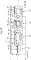
- Figure 2 shows the system 100 of Figure 1 in more detail.
- Figure 2A shows further details of the convolutional network 4
- Figure 2B shows further details of the fully connected network 8
- Figure 2C shows further details of the deconvolutional network 6
- Figure 2D shows further details of the filter 10.
- the convolutional network 4 ( Figure 2A ) includes an input for receiving the radar data, which as noted above may be in the form of an input matrix 2. Again, in this embodiment, the input matrix has dimensions ExAxD.
- the convolutional network 4 also includes a plurality of hidden layers 80, 82.
- the hidden layers 80, 82 may be arranged in a linear sequence.
- the convolutional network 4 may in principal include any number of hidden layers - for clarity only the first hidden layer 80 and the m th hidden layer 82 are shown in Figure 2A .
- the hidden layers 80, 82 each include a convolution layer 47.
- the convolution layers 47 of the hidden layers 80, 82 are operable to extract features from the radar data for subsequent classification by the deconvolutional network 6.
- Each convolution layer 47 may comprise a perceptron cube 48, 56.
- the perceptron cubes 48, 56 shown in the figures outlines the envelope of available perceptrons that may be supported by the system 100.
- the cubes 46, 54 shown in the figures illustrate the perceptrons that may be employed by a given application, depending on the dimensions of the input matrix 2.
- Each hidden layer 80, 82 may also include a subsampling layer 49.
- Each subsampling layer 49 may comprise a perceptron cube 52, 60.
- the perceptron cubes 52, 60 shown in the figures outlines the envelope of available perceptrons that may be supported by the system 100.
- the cubes 50, 58 shown in the figures illustrate the perceptrons that may be employed by a given application, again depending on the dimensions of the input matrix 2.
- each hidden layer 80, 82 may be connected to the preceding convolution layer 47 by a layer connector fabric 90.
- each convolution layer 47 in each hidden layer 80, 82 may be connected to the (e.g. subsampling layer 49 of the) preceding hidden layer by a layer connector fabric 90.
- the layer connector fabric 90 of the first hidden layer 80 connects the first convolution layer 47 to the input of the convolutional network to receive the input matrix 2.
- x, y, z, s, t and w are all programmable parameters and can be supported up to maximum of X, Y, Z, R, S and T respectively.
- X, Y and Z are used as symbols for dimensions of convolution layers 47 while R, S and T are used for dimensions of subsampling layers 49.
- perceptron cube is not limited to a cubic arrangement of perceptrons, and it will be understood that the dimensions of each perceptron cube may not be equal to each other.
- Each perceptron cube may by implemented as one or more hardware layers.
- the convolutional network 4 also includes an output located at the end of the sequence of hidden layers 80, 82.
- the output may be considered to be the output of the m th hidden layer (e.g. the output of the subsampling layer 49 of the hidden layer 82).
- Figure 2A also shows the skip connections bus 11.
- the arrows 13 schematically show the connections between the skip connections bus 11 and the various layers of the convolutional network 4.
- FIG 2A further shows the controller 30.
- the controller may be connected to each layer connector fabric 90 in the system 100 (see also the layer connector fabrics 90 in Figures 2B and 2C to be described below. This can allow the controller 30 to control parameters such as the stride size, padding size and dropout ratio for the (layers in the) convolutional network 4, the deconvolutional network 6 and/or the fully connected network 8 of the neural network architecture.
- the controller 30 may also be operable to control the skip connections bus 11, for selectively coupling (and decoupling) the skip connections 13 of the bus 11.
- the deconvolutional network 6 includes an input for receiving the output of the convolutional network 4.
- the deconvolutional network 6 may be connected to the convolutional network 4 by a data bus 12.
- the input of the deconvolutional network 6 may be formed by a layer connector fabric 90 as shown in Figure 2C which receives the output of the convolutional network 4.
- the layers of the deconvolutional network 6 up sample the output of the convolutional network 4 and classify the features extracted from the radar data by the convolutional network 4.
- a first layer 61 of deconvolutional network 6 may be a 1x1 convolution layer with K filters. Note that in Figure 2C , K denotes the number of filters supported by the system 100, whereas k denotes the number of filters actually used for a given application.
- the deconvolutional network 6 also includes a plurality of hidden layers 84, 86, 88.
- the hidden layers 84, 86, 88 may be arranged in a linear sequence.
- the deconvolutional network 6 may in principal include any number of hidden layers - for clarity only the first hidden layer 84, a p th hidden layer 86 and a (final) q th hidden layer 88 are shown in Figure 2C .
- the hidden layers 84, 86, 88 each include a deconvolution layer 63.
- the deconvolution layers 63 of the hidden layers 84, 86, 88 are operable to classify the features extracted from the radar data by the convolutional network 4.
- Each deconvolution layer 63 may comprise a perceptron cube 68, 72, 76.
- the perceptron cubes 68, 72, 76 shown in the figures outline the envelope of available perceptrons that may be supported by the system 100.
- the cubes 66, 70, 74 shown in the figures illustrate the perceptrons that may be employed by a given application.
- Each deconvolution layer 63 in each hidden layer 84, 86, 88 may be connected to the (e.g. deconvolution layer 63 of the) preceding hidden layer by a layer connector fabric 90. Note that the layer connector fabric 90 of the first hidden layer 84 connects the first deconvolution layer 63 to the first layer 61.
- u, v, w are all programmable parameters of the deconvolution layers 63 and can be supported up to maximum of U, V and W, respectively.
- the deconvolution layer 63 of the first hidden layer 84 is operable to up sample the output of the 1x1 convolution layer (the first layer 61) of deconvolutional network 6.
- a plurality of hidden layer 84, 86 comprising deconvolution layers 63 may follow the first hidden layer 84. These following layers may be selectively connectable to the skip connections bus 11.
- the (q th ) deconvolution layer 63 of the final hidden layer in the sequence of hidden layers in the deconvolutional network 6 may have the dimensions ExAx[Dx(C+1)] where C is the number of distinct classes that may be determined by the system 100 for features in the radar data that are extracted by the convolutional network 4.
- the deconvolutional network 6 also includes a classification output located at the end of the sequence of hidden layers 84, 86, 88. In the present embodiment the output may be considered to be the output of the deconvolution layer 63 of the final hidden layer 88.
- the classification output outputs the radar data including classification of the features extracted from the radar data by the convolutional network 4.
- Figure 2C shows the skip connections bus 11, in which the arrows 13 schematically show the connections between the skip connections bus 11 and the various layers of the deconvolutional network 6. Note that in this embodiment, there is no skip connection between the skip connections bus 11 and the first hidden layer 84.
- the fully connected network 8 has an input coupled to the bus 12 for receiving the output of the convolutional network 4.
- the fully connected network 8 has a plurality of fully connected layers (1, j, j+1, j+2...), which may be arranged in a linear sequence.
- the input may be received by a layer connector fabric 90 located before a first layer of the sequence.
- Each fully connected layer in the sequence may be coupled to a following/preceding fully connected layer by a layer connector fabric 90.
- Figure 2B shows a subset of the fully connected layers of the fully connected network 8 in this embodiment.
- the fully connected layers of the fully connected network 8 may typically have a depth of 1.
- the cubes 94, 98, 102, 106 show the envelope (F) supported by the system for each layer, while the cubes 92, 96, 100, 104 show the parts (f) of the supported envelope that are actually used for a given application.
- the fully connected network 8 also has an output, which is supplied to the filter 10 by a connection 130.
- the fully connected network 8 is operable to straighten features learned from the convolutional network 4 and supply a clutter threshold value 110 to output supplied to the filter 10.
- the clutter threshold value 110 may be a single value, and may comprise a radar cross section value.
- the clutter threshold value 110 may be denoted Th, and in this embodiment may be calculated in accordance with the Rectified Linear (ReLu) activation function (in particular, the clutter threshold value 110 may form the "zero point" of the ReLu function as shown schematically in Figure 4 ).
- the filter 10 may have a filter layer 120 comprising a cube of "biased" Rectified Linear Units (ReLU) with same dimensions ExAx[Dx(C+1)] as output of deconvolutional network 6.
- the cube 114 shows the envelope of supported units (U), while the cube 112 shows the units that are actually used for a given application.
- the cube of the filter 10 may typically have the same dimensions as the output of the deconvolutional network 6, so that the filter 10 can correctly receive and filter the output of the deconvolutional network 6.
- the filter 10 receives the clutter threshold value 110 via the connection 130.
- the filter 10 uses the clutter threshold value 110 to filter the output of the deconvolutional network 6.
- the filter 10 outputs zero for any (e.g. RCS) values in the output of the deconvolutional network 6 that fall below the clutter threshold value.
- the filter returns any value of the output of the deconvolutional network 6 that falls above the clutter threshold value.
- the operation of the fully connected network 8 and the filter 10, to calculate the clutter threshold value 110 and applying it in a filtering step may help in a backpropagation stage of training the neural network, where it may improve in the classification of objects of interest against clutter.
- Figure 3 compares the dimensions of the input matrix 2 and output 20 of the neural network architecture of Figure 1 according to an embodiment of this disclosure.
- the input matrix 2 may have dimensions ExAxD.
- the output 20 may be made up of a matrix including C+1 sections, each section having the dimensions ExAxD, whereby the overall dimensions of the output matrix are ExAx[Dx(C+1)].
- C is the number of distinct classes that may be determined by the system 100 for features in the radar data that are extracted by the convolutional network 4.
- the "1" in the term "C+1" denotes an additional class, allocated to unclassified objects.
- the layer connector fabrics 90 described herein may be considered to be an abstracted illustration of data-mapping through mathematical operation between two layers of the system 100.
- each layer connector fabric 90 may, for instance:
- the layer connector fabric 90 may, for instance, apply a max-pooling, mean-pooling, min-pooling or a similar operation as is known in the art. The choice of operation that is used may be controlled by the controller 30.
- the layer connector fabric 90 may be a 2-dimensional convolution operation, dropout, flatten (for the last convolutional layer in the sequence), or another similar operation.
- the layer connector fabric 90 may be an up-sampling operation instead of a sub-sampling operation as in convolutional network 4.
- a method of classifying objects using radar data may be performed as follows. This method may be implemented by, for example, the system of Figures 1 and 2 .
- the method may include obtaining radar data.
- the radar data may be obtained by a vehicle radar system of a vehicle.
- the radar data may be received (e.g. from the vehicle radar system) by a convolutional network.
- the convolutional network may be a convolutional network 4 of the kind described above in relation to Figures 1 and 2 .
- the radar data may be provided to the convolutional network in the form of an input matrix, such as the input matrix 2.
- the method may also include the convolutional network using a plurality of hidden layers comprising convolution layers to extract features from the radar data. These features may generally relate and correspond to the objects to be classified by the method.
- the method may further include a deconvolutional network (e.g. the deconvolutional network 6 described above in relation to Figures 1 and 2 ) receiving an output of the convolutional network.
- the output of the convolutional network generally comprises processed radar data in which extracted features have been identified by the convolutional network.
- the deconvolutional network may be coupled to the convolutional network by a data bus (e.g. the bus 12).
- the method may also include the deconvolutional network using a plurality of hidden layers comprising deconvolution layers to classify the features extracted from the radar data by the convolutional network.
- the method may further include the deconvolutional network providing a classification output, which may output processed radar data in which the extracted features identified by the convolutional network are classified.
- the method may further include a fully connected network receiving the output of the convolutional network (e.g. via the bus 12), and then using a plurality of fully connected layers to determine a clutter threshold value from the output of the convolutional network.
- a fully connected network receiving the output of the convolutional network (e.g. via the bus 12), and then using a plurality of fully connected layers to determine a clutter threshold value from the output of the convolutional network.
- the method may also include a filter using the clutter threshold value to filter noise and/or clutter from the classification output of the deconvolutional network to produce a filtered classification output.
- the method may include selectively coupling a skip connection between the convolutional network and the deconvolutional network for bypassing at least some of the convolution layers and deconvolution layers, as has been explained previously.
- the system of Figure 1 may be incorporated into, for example, a hardware accelerator or a graphics processing unit.
- the hardware accelerator or graphics processing unit may be provided in a vehicle, for instance as part of a vehicle radar system of the vehicle.
- the vehicle may, for instance, be a road vehicle such as a car, truck, lorry, van or bike.
- the system includes a convolutional network having a plurality of hidden layers comprising convolution layers for extracting features from the radar data, and an output.
- the system also includes a deconvolutional network having a plurality of hidden layers comprising deconvolution layers for classifying the features extracted from the radar data, and a classification output.
- the system also includes a filter having an input coupled to the classification output of the deconvolutional network.
- the system further includes a fully connected network having a plurality of fully connected layers for determining a clutter threshold value from the output of the convolutional network.
- the filter is operable to use the clutter threshold value to filter noise and/or clutter from the classification output of the deconvolutional network and pass a filtered classification output to an output of the system.
Landscapes
- Engineering & Computer Science (AREA)
- Remote Sensing (AREA)
- Radar, Positioning & Navigation (AREA)
- Physics & Mathematics (AREA)
- Computer Networks & Wireless Communication (AREA)
- General Physics & Mathematics (AREA)
- Electromagnetism (AREA)
- Artificial Intelligence (AREA)
- Evolutionary Computation (AREA)
- Traffic Control Systems (AREA)
- Radar Systems Or Details Thereof (AREA)
Abstract
Description
- The present specification relates to a system operable to classify objects using radar data obtained by an automotive radar. The present specification also relates to a hardware accelerator or graphics processing unit comprising the system. The present specification further relates to a vehicle comprising the hardware accelerator or the graphics processing unit. The present specification also relates to a method of classifying objects using radar data obtained by an automotive radar.
- With the advancements in automotive radars over the years, the applications have gone beyond mere detection of objects. Imaging radars are now capable of reflecting several points from targets. However, the processing capability of automotive radar sensors (in terms of classification) is lacking behind.
- Aspects of the present disclosure are set out in the accompanying independent and dependent claims. Combinations of features from the dependent claims may be combined with features of the independent claims as appropriate and not merely as explicitly set out in the claims.
- According to an aspect of the present disclosure, there is provided a system operable to classify objects using radar data obtained by an automotive radar, the system comprising:
- a convolutional network comprising:
- an input for receiving the radar data;
- a plurality of hidden layers comprising convolution layers for extracting features from the radar data;
- and an output;
- a bus coupled to the output of the convolutional network;
- a deconvolutional network comprising:
- an input coupled to the bus to receive the output of the convolutional network,
- a plurality of hidden layers comprising deconvolution layers for classifying the features extracted from the radar data by the convolutional network; and
- a classification output;
- a filter having an input coupled to the classification output of the deconvolutional network;
- a fully connected network comprising:
- an input coupled to the bus for receiving the output of the convolutional network;
- a plurality of fully connected layers for determining a clutter threshold value from the output of the convolutional network; and
- an output connected to the filter to provide the clutter threshold value to the filter; and
- an output coupled to the filter,
- According to another aspect of the present disclosure, there is provided a method of classifying objects using radar data obtained by an automotive radar, the method comprising:
- a convolutional network:
- receiving the radar data; and
- using a plurality of hidden layers comprising convolution layers to extract features from the radar data;
- a deconvolutional network:
- receiving an output of the convolutional network;
- using a plurality of hidden layers comprising deconvolution layers to classify the features extracted from the radar data by the convolutional network; and
- providing a classification output;
- a fully connected network:
- receiving the output of the convolutional network; and
- using a plurality of fully connected layers to determine a clutter threshold value from the output of the convolutional network; and
- a filter using the clutter threshold value to filter noise and/or clutter from the classification output of the deconvolutional network to produce a filtered classification output.
- The claimed system and method may improve the accuracy and consistency by which objects detected by a radar system can be classified. This may be achieved due to the provision of the filter, which filters out noise and/or clutter based on the clutter threshold value produced by the fully connected network, to produce the filtered classification output.
- The system of may further comprise a skip connections bus having one or more skip connections coupleable between the convolutional network and the deconvolutional network. This can allow at least some of the convolution layers and deconvolution layers to be bypassed. This can allow the fast/efficient classification of objects to be achieved.
- Each skip connection may allow high-level extracted features learned during early convolution layers of the convolutional network to be passed directly to the deconvolutional network.
- The system may be operable selectively to couple/decouple a skip connection between a convolution layer and a deconvolution layer.
- The filter may be operable to filter out any detected features having a value less than the clutter threshold value.
- The value of each detected feature may comprise a radar cross section value.
- The clutter threshold value may be a single value.
- The system may comprise a controller for controlling at least one of: a stride size; a padding size; and a dropout ratio, for each layer in the convolutional and/or deconvolutional network.
- The radar data may comprise at least one of range, doppler and spatial information.
- The filtered classification output may classify objects detected by the automotive radar. Examples of such objects include vehicles, street furniture, building and pedestrians.
- The system and method described herein may use various activation functions of the kind that are known in the art of neural networks. For instance, the activation function may be a linear activation function, a step activation function, a hyperbolic tangent activation function of a Rectified Linear (ReLu) activation function. The clutter threshold value may be calculated in accordance with the activation function.
- The method may comprise selectively coupling a skip connection between the convolutional network and the deconvolutional network for bypassing at least some of the convolution layers and deconvolution layers.
- According to a further aspect of the present disclosure, there is provided a hardware accelerator comprising the system of any of
claims 1 to 10. - According to another aspect of the present disclosure, there is provided a graphics processing unit comprising the system of any of
claims 1 to 10. - According to a further aspect of the present disclosure, there is provided a vehicle comprising the hardware accelerator of
claim 11 or the graphics processing unit ofclaim 12. - Embodiments of this disclosure will be described hereinafter, by way of example only, with reference to the accompanying drawings in which like reference signs relate to like elements and in which:
-
Figure 1 shows a system comprising a neural network architecture according to an embodiment of this disclosure; -
Figure 2A shows the convolutional network of the neural network architecture ofFigure 1 in more detail, according to an embodiment of this disclosure; -
Figure 2B shows the fully connected network of the neural network architecture ofFigure 1 in more detail, according to an embodiment of this disclosure; -
Figure 2C shows the deconvolutional network of the neural network architecture ofFigure 1 in more detail, according to an embodiment of this disclosure; -
Figure 2D shows the filter of the neural network architecture ofFigure 1 in more detail, according to an embodiment of this disclosure; -
Figure 3 compares the dimensions of the input and output of the neural network architecture ofFigure 1 according to an embodiment of this disclosure; and -
Figure 4 shows a ReLu activation function and clutter threshold value according to an embodiment of this disclosure. - Embodiments of this disclosure are described in the following with reference to the accompanying drawings.
-
Figure 1 shows asystem 100 comprising a neural network architecture according to an embodiment of this disclosure. Thesystem 100 is operable to classify objects using radar data. The radar data is typically radar data that has been acquired by a vehicle radar. Accordingly, examples of objects to be classified include vehicles, street furniture, building and pedestrians. The radar data may, for instance, comprise range, doppler and spatial information. - The
system 100 includes aconvolutional network 4. Theconvolutional network 4 includes an input that for receiving the radar data. Theconvolutional network 4 comprises a set of hidden layers. The hidden layers may include convolution layers and/or subsampling layers. The hidden layers are operable to extract features from the radar data received at the input. Theconvolutional network 4 further includes an output. - The radar data may be in the form of an
input matrix 2 comprising a plurality of radar data values. In one embodiment, the dimensions of theinput matrix 2 may be ExAxD, where E is the number of elevation points, A is the number of azimuth points and D is the number of distance points in theinput matrix 2. V and RCS may be the channels of theinput matrix 2, where V is the number of velocity points and RCS is the radar cross section. - The
system 100 also includes abus 12. Thebus 12 is coupled to the output of theconvolutional network 4, for providing the output of the convolutional network 4 (processed radar data in which extracted features have been identified by the convolutional network) to other parts of thesystem 100. - The
system 100 further includes adeconvolutional network 6. Thedeconvolutional network 6 includes an input, which is connected to thebus 12 for receiving the output of theconvolutional network 4. Thedeconvolutional network 6 also includes a plurality of hidden layers. The hidden layers include deconvolution layers for classifying the features extracted from theradar data 2 by theconvolutional network 4. Thedeconvolutional network 6 also includes a classification output, from which processed radar data in which the extracted features identified by theconvolutional network 4 are classified. - The
system 100 also includes afilter 10. Thefilter 10 has an input, which is coupled to the classification output of thedeconvolutional network 6. The filter may comprise a filter layer located after a final one of the deconvolution layers in the sequence of deconvolution layers in thedeconvolutional network 6. - The
system 100 further includes a fully connectednetwork 8. The fully connectednetwork 8 has an input which is coupled to thebus 12 for receiving the output of theconvolutional network 4. The fully connectednetwork 8 also includes a plurality of fully connected layers. The fully connected layers are operable to determine a clutter threshold value from the output of theconvolutional network 6. The fully connectednetwork 8 further includes an output, which is connected to the filter 10 (e.g. by connection 130) to provide the clutter threshold value to thefilter 10. - The neural network architecture of the
system 100 ofFigure 1 may use various activation functions of the kind that are known in the art of neural networks. For instance, the activation function may be a linear activation function, a step activation function, a hyperbolic tangent activation function of a Rectified Linear (ReLu) activation function. The clutter threshold value may be calculated in accordance with the activation function. - The
filter 10 is operable to use the clutter threshold value provided by the fully connectednetwork 8 to filter noise and/or clutter from the classification output of thedeconvolutional network 6. Thefilter 10 thereby produces a filtered classification output, which is then passed to theoutput 20 of the system. - The
system 100 may also include askip connections bus 11. Theskip connections bus 11 includes one or more skip connections. The skip connections may be selectively coupleable between theconvolutional network 4 and thedeconvolutional network 6. In particular, and noting that the convolution layers of a convolutional network and the deconvolution layers of the deconvolutional network are typically provided in a linear sequence, the skip connections may be selectively coupleable between a convolution layer of theconvolutional network 4 and a deconvolution layer of thedeconvolutional network 6, so as to bypass any intervening convolution layers and deconvolution layers in the sequence. It is envisaged that theskip connections bus 11 may include skip connections for selectively coupling any convolution layer of theconvolutional network 4 with any deconvolution layer of thedeconvolutional network 6, to allow intervening layers to be bypassed in this way. Typically, however during one object classification operation, only one convolution layer would be connected to any one deconvolution layer. - The skip connections of the
skip connections bus 11 can allow high-level extracted features that are learned during early convolution layers in the sequence of convolution layers of theconvolutional network 4 to be passed directly to thedeconvolutional network 6. Data can be fed from an early convolution layer of the convolutional network 4 (in addition to from the end of sequence of convolution layers outputted from the convolutional network 4), into a deconvolution layer of thedeconvolutional network 6, thereby to retain high-level features (for instance the contours of an object) learned during early convolution layers of theconvolutional network 4. This may significantly increase the speed and efficiency by which objects may be classified by thesystem 100. - The
system 100 may further include acontroller 30. Thecontroller 30 may be operable control certain operational parameters of thesystem 100, including, for instance, a stride size, a padding size and a dropout ratio for the (layers in the)convolutional network 4, thedeconvolutional network 6 and/or the fully connectednetwork 8 of the neural network architecture. Thecontroller 30 may also be operable to control theskip connections bus 11, for selectively coupling (and decoupling) the skip connections of thebus 11 between the between the convolution layers of theconvolutional network 4 and the deconvolution layers of thedeconvolutional network 6 as noted above. -
Figure 2 shows thesystem 100 ofFigure 1 in more detail. In particular,Figure 2A shows further details of theconvolutional network 4,Figure 2B shows further details of the fully connectednetwork 8,Figure 2C shows further details of thedeconvolutional network 6 andFigure 2D shows further details of thefilter 10. - The convolutional network 4 (
Figure 2A ) includes an input for receiving the radar data, which as noted above may be in the form of aninput matrix 2. Again, in this embodiment, the input matrix has dimensions ExAxD. - The
convolutional network 4 also includes a plurality ofhidden layers convolutional network 4 may in principal include any number of hidden layers - for clarity only the first hiddenlayer 80 and the mth hiddenlayer 82 are shown inFigure 2A . The hidden layers 80, 82 each include aconvolution layer 47. The convolution layers 47 of thehidden layers deconvolutional network 6. - Each
convolution layer 47 may comprise aperceptron cube perceptron cubes system 100. On the other hand, thecubes input matrix 2. - Each hidden
layer subsampling layer 49. Eachsubsampling layer 49 may comprise aperceptron cube perceptron cubes system 100. On the other hand, thecubes input matrix 2. - The
subsampling layer 49 in eachhidden layer convolution layer 47 by alayer connector fabric 90. Similarly, eachconvolution layer 47 in eachhidden layer layer 49 of the) preceding hidden layer by alayer connector fabric 90. Note that thelayer connector fabric 90 of the first hiddenlayer 80 connects thefirst convolution layer 47 to the input of the convolutional network to receive theinput matrix 2. - In the figures, x, y, z, s, t and w are all programmable parameters and can be supported up to maximum of X, Y, Z, R, S and T respectively. Note that X, Y and Z are used as symbols for dimensions of convolution layers 47 while R, S and T are used for dimensions of subsampling layers 49.
- For the purposes of the present application, the term perceptron cube is not limited to a cubic arrangement of perceptrons, and it will be understood that the dimensions of each perceptron cube may not be equal to each other. Each perceptron cube may by implemented as one or more hardware layers.
- The
convolutional network 4 also includes an output located at the end of the sequence ofhidden layers subsampling layer 49 of the hidden layer 82). -
Figure 2A also shows theskip connections bus 11. Thearrows 13 schematically show the connections between theskip connections bus 11 and the various layers of theconvolutional network 4. -
Figure 2A further shows thecontroller 30. The controller may be connected to eachlayer connector fabric 90 in the system 100 (see also thelayer connector fabrics 90 inFigures 2B and2C to be described below. This can allow thecontroller 30 to control parameters such as the stride size, padding size and dropout ratio for the (layers in the)convolutional network 4, thedeconvolutional network 6 and/or the fully connectednetwork 8 of the neural network architecture. Again, thecontroller 30 may also be operable to control theskip connections bus 11, for selectively coupling (and decoupling) theskip connections 13 of thebus 11. - Turning to
Figure 2C , thedeconvolutional network 6 includes an input for receiving the output of theconvolutional network 4. As described in relation toFigure 1 , thedeconvolutional network 6 may be connected to theconvolutional network 4 by adata bus 12. In this embodiment, the input of thedeconvolutional network 6 may be formed by alayer connector fabric 90 as shown inFigure 2C which receives the output of theconvolutional network 4. - The layers of the
deconvolutional network 6 up sample the output of theconvolutional network 4 and classify the features extracted from the radar data by theconvolutional network 4. - A
first layer 61 ofdeconvolutional network 6 may be a 1x1 convolution layer with K filters. Note that inFigure 2C , K denotes the number of filters supported by thesystem 100, whereas k denotes the number of filters actually used for a given application. - The
deconvolutional network 6 also includes a plurality ofhidden layers deconvolutional network 6 may in principal include any number of hidden layers - for clarity only the first hiddenlayer 84, a pth hidden layer 86 and a (final) qth hiddenlayer 88 are shown inFigure 2C . The hidden layers 84, 86, 88 each include adeconvolution layer 63. As noted above, the deconvolution layers 63 of thehidden layers convolutional network 4. - Each
deconvolution layer 63 may comprise aperceptron cube perceptron cubes system 100. On the other hand, thecubes - Each
deconvolution layer 63 in eachhidden layer e.g. deconvolution layer 63 of the) preceding hidden layer by alayer connector fabric 90. Note that thelayer connector fabric 90 of the first hiddenlayer 84 connects thefirst deconvolution layer 63 to thefirst layer 61. - In the figures, u, v, w are all programmable parameters of the deconvolution layers 63 and can be supported up to maximum of U, V and W, respectively.
- The
deconvolution layer 63 of the first hiddenlayer 84 is operable to up sample the output of the 1x1 convolution layer (the first layer 61) ofdeconvolutional network 6. A plurality of hiddenlayer 84, 86 comprising deconvolution layers 63 may follow the first hiddenlayer 84. These following layers may be selectively connectable to theskip connections bus 11. - The (qth)
deconvolution layer 63 of the final hidden layer in the sequence of hidden layers in thedeconvolutional network 6 may have the dimensions ExAx[Dx(C+1)] where C is the number of distinct classes that may be determined by thesystem 100 for features in the radar data that are extracted by theconvolutional network 4. - The
deconvolutional network 6 also includes a classification output located at the end of the sequence ofhidden layers deconvolution layer 63 of the final hiddenlayer 88. The classification output outputs the radar data including classification of the features extracted from the radar data by theconvolutional network 4. - Again,
Figure 2C shows theskip connections bus 11, in which thearrows 13 schematically show the connections between theskip connections bus 11 and the various layers of thedeconvolutional network 6. Note that in this embodiment, there is no skip connection between theskip connections bus 11 and the first hiddenlayer 84. - Turning to
Figure 2B , the fully connectednetwork 8 has an input coupled to thebus 12 for receiving the output of theconvolutional network 4. The fully connectednetwork 8 has a plurality of fully connected layers (1, j, j+1, j+2...), which may be arranged in a linear sequence. In the present embodiment, the input may be received by alayer connector fabric 90 located before a first layer of the sequence. Each fully connected layer in the sequence may be coupled to a following/preceding fully connected layer by alayer connector fabric 90. For clarity,Figure 2B shows a subset of the fully connected layers of the fully connectednetwork 8 in this embodiment. - The fully connected layers of the fully connected
network 8 may typically have a depth of 1. As before, inFigure 2B , thecubes cubes - The fully connected
network 8 also has an output, which is supplied to thefilter 10 by aconnection 130. The fully connectednetwork 8 is operable to straighten features learned from theconvolutional network 4 and supply aclutter threshold value 110 to output supplied to thefilter 10. Theclutter threshold value 110 may be a single value, and may comprise a radar cross section value. Theclutter threshold value 110 may be denoted Th, and in this embodiment may be calculated in accordance with the Rectified Linear (ReLu) activation function (in particular, theclutter threshold value 110 may form the "zero point" of the ReLu function as shown schematically inFigure 4 ). - Turning to
Figure 2D , thefilter 10 may have afilter layer 120 comprising a cube of "biased" Rectified Linear Units (ReLU) with same dimensions ExAx[Dx(C+1)] as output ofdeconvolutional network 6. As before, inFigure 2D , thecube 114 shows the envelope of supported units (U), while thecube 112 shows the units that are actually used for a given application. Note that the cube of thefilter 10 may typically have the same dimensions as the output of thedeconvolutional network 6, so that thefilter 10 can correctly receive and filter the output of thedeconvolutional network 6. - As noted above, the
filter 10 receives theclutter threshold value 110 via theconnection 130. Thefilter 10 uses theclutter threshold value 110 to filter the output of thedeconvolutional network 6. In this embodiment, where the ReLu function is used as the activation function, thefilter 10 outputs zero for any (e.g. RCS) values in the output of thedeconvolutional network 6 that fall below the clutter threshold value. On the other hand, the filter returns any value of the output of thedeconvolutional network 6 that falls above the clutter threshold value. Collectively, these values, and the zero values (filtered out because the corresponding values in the output from thedeconvolutional network 6 fell below the clutter threshold value) form a filtered classification output of thefilter 10. Thefilter 10 is operable to pass this filtered classification output to theoutput 20 of the system. - The operation of the fully connected
network 8 and thefilter 10, to calculate theclutter threshold value 110 and applying it in a filtering step may help in a backpropagation stage of training the neural network, where it may improve in the classification of objects of interest against clutter. -
Figure 3 compares the dimensions of theinput matrix 2 andoutput 20 of the neural network architecture ofFigure 1 according to an embodiment of this disclosure. As mentioned previously, theinput matrix 2 may have dimensions ExAxD. Theoutput 20 may be made up of a matrix including C+1 sections, each section having the dimensions ExAxD, whereby the overall dimensions of the output matrix are ExAx[Dx(C+1)]. Here, C is the number of distinct classes that may be determined by thesystem 100 for features in the radar data that are extracted by theconvolutional network 4. Note that the "1" in the term "C+1" denotes an additional class, allocated to unclassified objects. - The
layer connector fabrics 90 described herein may be considered to be an abstracted illustration of data-mapping through mathematical operation between two layers of thesystem 100. - For the
convolutional network 4, eachlayer connector fabric 90 may, for instance: - connect elements of a
convolution layer 47, as input to the operation, to the elements of a next sub-sampling layer 49 (of the same hiddenlayer 80, 82) as output of the operation, or - connect or elements of a
sub-sampling layer 49, as input of the operation, to theconvolutional layer 47 of subsequent hidden layer ofconvolutional network 4. - In case of a connection between a
convolutional layer 47 and itssuccessive sub-sampling layer 49, thelayer connector fabric 90 may, for instance, apply a max-pooling, mean-pooling, min-pooling or a similar operation as is known in the art. The choice of operation that is used may be controlled by thecontroller 30. - In case of a connection between a
sub-sampling layer 49 of a preceding hidden layer andconvolution layer 47 of a following hidden layer, thelayer connector fabric 90 may be a 2-dimensional convolution operation, dropout, flatten (for the last convolutional layer in the sequence), or another similar operation. - For deconvolution layers 63 in the
deconvolutional network 6, thelayer connector fabric 90 may be an up-sampling operation instead of a sub-sampling operation as inconvolutional network 4. - A method of classifying objects using radar data may be performed as follows. This method may be implemented by, for example, the system of
Figures 1 and2 . - The method may include obtaining radar data. The radar data may be obtained by a vehicle radar system of a vehicle. The radar data may be received (e.g. from the vehicle radar system) by a convolutional network. The convolutional network may be a
convolutional network 4 of the kind described above in relation toFigures 1 and2 . As explained previously, the radar data may be provided to the convolutional network in the form of an input matrix, such as theinput matrix 2. - The method may also include the convolutional network using a plurality of hidden layers comprising convolution layers to extract features from the radar data. These features may generally relate and correspond to the objects to be classified by the method.
- The method may further include a deconvolutional network (e.g. the
deconvolutional network 6 described above in relation toFigures 1 and2 ) receiving an output of the convolutional network. The output of the convolutional network generally comprises processed radar data in which extracted features have been identified by the convolutional network. The deconvolutional network may be coupled to the convolutional network by a data bus (e.g. the bus 12). - The method may also include the deconvolutional network using a plurality of hidden layers comprising deconvolution layers to classify the features extracted from the radar data by the convolutional network. The method may further include the deconvolutional network providing a classification output, which may output processed radar data in which the extracted features identified by the convolutional network are classified.
- The method may further include a fully connected network receiving the output of the convolutional network (e.g. via the bus 12), and then using a plurality of fully connected layers to determine a clutter threshold value from the output of the convolutional network.
- The method may also include a filter using the clutter threshold value to filter noise and/or clutter from the classification output of the deconvolutional network to produce a filtered classification output.
- In some embodiments, the method may include selectively coupling a skip connection between the convolutional network and the deconvolutional network for bypassing at least some of the convolution layers and deconvolution layers, as has been explained previously.
- The system of
Figure 1 may be incorporated into, for example, a hardware accelerator or a graphics processing unit. The hardware accelerator or graphics processing unit may be provided in a vehicle, for instance as part of a vehicle radar system of the vehicle. The vehicle may, for instance, be a road vehicle such as a car, truck, lorry, van or bike. - Accordingly, there has been described a system and method to classify objects using radar data obtained by an automotive radar. The system includes a convolutional network having a plurality of hidden layers comprising convolution layers for extracting features from the radar data, and an output. The system also includes a deconvolutional network having a plurality of hidden layers comprising deconvolution layers for classifying the features extracted from the radar data, and a classification output. The system also includes a filter having an input coupled to the classification output of the deconvolutional network. The system further includes a fully connected network having a plurality of fully connected layers for determining a clutter threshold value from the output of the convolutional network. The filter is operable to use the clutter threshold value to filter noise and/or clutter from the classification output of the deconvolutional network and pass a filtered classification output to an output of the system.
- Although particular embodiments of this disclosure have been described, it will be appreciated that many modifications/additions and/or substitutions may be made within the scope of the claims.
Claims (15)
- A system operable to classify objects using radar data obtained by an automotive radar, the system comprising:a convolutional network comprising:an input for receiving the radar data;a plurality of hidden layers comprising convolution layers for extracting features from the radar data;and an output;a bus coupled to the output of the convolutional network;a deconvolutional network comprising:an input coupled to the bus to receive the output of the convolutional network,a plurality of hidden layers comprising deconvolution layers for classifying the features extracted from the radar data by the convolutional network; anda classification output;a filter having an input coupled to the classification output of the deconvolutional network;a fully connected network comprising:an input coupled to the bus for receiving the output of the convolutional network;a plurality of fully connected layers for determining a clutter threshold value from the output of the convolutional network; andan output connected to the filter to provide the clutter threshold value to the filter; andan output coupled to the filter,wherein the filter is operable to use the clutter threshold value to filter noise and/or clutter from the classification output of the deconvolutional network and pass a filtered classification output to the output of the system.
- The system of claim 1 further comprising a skip connections bus having one or more skip connections coupleable between the convolutional network and the deconvolutional network for bypassing at least some of the convolution layers and deconvolution layers.
- The system of claim 2, wherein each skip connection allows high-level extracted features learned during early convolution layers of the convolutional network to be passed directly to the deconvolutional network.
- The system of claim 2 or claim 3, operable selectively to couple/decouple a said skip connection between a said convolution layer and a said deconvolution layer.
- The system of any preceding claim, wherein the filter is operable to filter out any detected features having a value less than the clutter threshold value.
- The system of claim 5, wherein the value of each detected feature comprises a radar cross section value.
- The system of any preceding claim, wherein the clutter threshold value is a single value.
- The system of any preceding claim comprising a controller for controlling at least one of:a stride size;a padding size; anda dropout ratio,for each layer in the convolutional and/or deconvolutional network.
- The system of any preceding claim, wherein the radar data comprises at least one of range, doppler and spatial information.
- The system of any preceding claim, wherein the filtered classification output classifies objects detected by the automotive radar.
- A hardware accelerator comprising the system of any preceding claim.
- A graphics processing unit comprising the system of any of claims 1 to 10.
- A vehicle comprising the hardware accelerator of claim 11 or the graphics processing unit of claim 12.
- A method of classifying objects using radar data obtained by an automotive radar, the method comprising:a convolutional network:receiving the radar data; andusing a plurality of hidden layers comprising convolution layers to extract features from the radar data;a deconvolutional network:receiving an output of the convolutional network;using a plurality of hidden layers comprising deconvolution layers to classify the features extracted from the radar data by the convolutional network; andproviding a classification output;a fully connected network:receiving the output of the convolutional network; andusing a plurality of fully connected layers to determine a clutter threshold value from the output of the convolutional network; anda filter using the clutter threshold value to filter noise and/or clutter from the classification output of the deconvolutional network to produce a filtered classification output.
- The method of claim 14 comprising selectively coupling a skip connection between the convolutional network and the deconvolutional network for bypassing at least some of the convolution layers and deconvolution layers.
Priority Applications (2)
| Application Number | Priority Date | Filing Date | Title |
|---|---|---|---|
| EP19177910.7A EP3748392B1 (en) | 2019-06-03 | 2019-06-03 | System and method to classify objects using radar data |
| US16/865,601 US20200379103A1 (en) | 2019-06-03 | 2020-05-04 | System and method to classify objects using radar data |
Applications Claiming Priority (1)
| Application Number | Priority Date | Filing Date | Title |
|---|---|---|---|
| EP19177910.7A EP3748392B1 (en) | 2019-06-03 | 2019-06-03 | System and method to classify objects using radar data |
Publications (2)
| Publication Number | Publication Date |
|---|---|
| EP3748392A1 true EP3748392A1 (en) | 2020-12-09 |
| EP3748392B1 EP3748392B1 (en) | 2025-10-22 |
Family
ID=66690258
Family Applications (1)
| Application Number | Title | Priority Date | Filing Date |
|---|---|---|---|
| EP19177910.7A Active EP3748392B1 (en) | 2019-06-03 | 2019-06-03 | System and method to classify objects using radar data |
Country Status (2)
| Country | Link |
|---|---|
| US (1) | US20200379103A1 (en) |
| EP (1) | EP3748392B1 (en) |
Families Citing this family (1)
| Publication number | Priority date | Publication date | Assignee | Title |
|---|---|---|---|---|
| CN113189594B (en) * | 2020-12-28 | 2022-11-25 | 北京理工大学 | Weather radar echo classification method based on time continuity characteristics |
Citations (3)
| Publication number | Priority date | Publication date | Assignee | Title |
|---|---|---|---|---|
| EP1121608A1 (en) * | 1999-08-12 | 2001-08-08 | Automotive Systems Laboratory Inc. | Neural network radar processor |
| US20170262735A1 (en) * | 2016-03-11 | 2017-09-14 | Kabushiki Kaisha Toshiba | Training constrained deconvolutional networks for road scene semantic segmentation |
| CN107993215A (en) * | 2017-11-27 | 2018-05-04 | 象辑知源(武汉)科技有限公司 | A kind of weather radar image processing method and system |
Family Cites Families (4)
| Publication number | Priority date | Publication date | Assignee | Title |
|---|---|---|---|---|
| US6590519B2 (en) * | 1999-12-22 | 2003-07-08 | Hot/Shot Radar Inspections, Llc | Method and system for identification of subterranean objects |
| CN111095291B (en) * | 2018-02-27 | 2024-04-09 | 辉达公司 | Real-time lane and boundary detection by autonomous vehicles |
| US11068724B2 (en) * | 2018-10-11 | 2021-07-20 | Baidu Usa Llc | Deep learning continuous lane lines detection system for autonomous vehicles |
| US11313950B2 (en) * | 2019-01-15 | 2022-04-26 | Image Sensing Systems, Inc. | Machine learning based highway radar vehicle classification across multiple lanes and speeds |
-
2019
- 2019-06-03 EP EP19177910.7A patent/EP3748392B1/en active Active
-
2020
- 2020-05-04 US US16/865,601 patent/US20200379103A1/en not_active Abandoned
Patent Citations (3)
| Publication number | Priority date | Publication date | Assignee | Title |
|---|---|---|---|---|
| EP1121608A1 (en) * | 1999-08-12 | 2001-08-08 | Automotive Systems Laboratory Inc. | Neural network radar processor |
| US20170262735A1 (en) * | 2016-03-11 | 2017-09-14 | Kabushiki Kaisha Toshiba | Training constrained deconvolutional networks for road scene semantic segmentation |
| CN107993215A (en) * | 2017-11-27 | 2018-05-04 | 象辑知源(武汉)科技有限公司 | A kind of weather radar image processing method and system |
Non-Patent Citations (1)
| Title |
|---|
| KAIMING HE ET AL: "Deep Residual Learning for Image Recognition", 2016 IEEE CONFERENCE ON COMPUTER VISION AND PATTERN RECOGNITION (CVPR), 1 June 2016 (2016-06-01), pages 770 - 778, XP055536240, ISBN: 978-1-4673-8851-1, DOI: 10.1109/CVPR.2016.90 * |
Also Published As
| Publication number | Publication date |
|---|---|
| US20200379103A1 (en) | 2020-12-03 |
| EP3748392B1 (en) | 2025-10-22 |
Similar Documents
| Publication | Publication Date | Title |
|---|---|---|
| CN105242271B (en) | Target classification for vehicle radar system | |
| Nabati et al. | Rrpn: Radar region proposal network for object detection in autonomous vehicles | |
| US9733350B2 (en) | Vehicle radar control | |
| EP3929807B1 (en) | System and method for sensor fusion system having distributed convolutional neural network | |
| US20220180628A1 (en) | Information processing apparatus, information processing method, and information processing program | |
| CN112240999B (en) | Method and system for processing radar reflections | |
| CN110443138B (en) | Multi-target classification method based on vehicle-mounted millimeter-wave radar joint SVM and CNN | |
| CN109305165A (en) | Intelligent ultrasonic system, vehicle rear collision warning device and control method thereof | |
| DE102015110446A1 (en) | Vehicle radar with beam adjustment | |
| CN105335710A (en) | Fine vehicle model identification method based on multi-stage classifier | |
| US12546888B2 (en) | Method and processor circuit for operating a radar system comprising multiple antennas, radar system and motor vehicle | |
| WO2021247427A1 (en) | Clustering in automotive imaging | |
| CN109870692B (en) | Radar looking around system and data processing method | |
| Manzari et al. | Pyramid transformer for traffic sign detection | |
| CN116704304A (en) | A multi-modal fusion object detection method based on hybrid attention mechanism | |
| US11881028B2 (en) | Vehicle lidar system with neural network-based dual density point cloud generator | |
| WO2022129266A1 (en) | Method for detecting at least one object in surroundings by means of reflection signals of a radar sensor system | |
| Nowruzi et al. | Polarnet: Accelerated deep open space segmentation using automotive radar in polar domain | |
| US20200379103A1 (en) | System and method to classify objects using radar data | |
| RU91185U1 (en) | DEVICE OF TWO-LEVEL NEURAL NETWORK RECOGNITION OF AIR OBJECTS BY TOTAL SUMMARY | |
| CN116778449B (en) | Detection method for improving detection efficiency of three-dimensional target of automatic driving | |
| CN113646729A (en) | Methods for detecting and classifying poses using radar systems | |
| Mohammed et al. | Vehicle detection and classification using three variations of you only look once algorithm | |
| CN115115973A (en) | Weak and small target detection method based on multiple receptive fields and depth characteristics | |
| Varagula et al. | Object detection method in traffic by on-board computer vision with time delay neural network |
Legal Events
| Date | Code | Title | Description |
|---|---|---|---|
| PUAI | Public reference made under article 153(3) epc to a published international application that has entered the european phase |
Free format text: ORIGINAL CODE: 0009012 |
|
| STAA | Information on the status of an ep patent application or granted ep patent |
Free format text: STATUS: THE APPLICATION HAS BEEN PUBLISHED |
|
| AK | Designated contracting states |
Kind code of ref document: A1 Designated state(s): AL AT BE BG CH CY CZ DE DK EE ES FI FR GB GR HR HU IE IS IT LI LT LU LV MC MK MT NL NO PL PT RO RS SE SI SK SM TR |
|
| AX | Request for extension of the european patent |
Extension state: BA ME |
|
| STAA | Information on the status of an ep patent application or granted ep patent |
Free format text: STATUS: REQUEST FOR EXAMINATION WAS MADE |
|
| 17P | Request for examination filed |
Effective date: 20210609 |
|
| RBV | Designated contracting states (corrected) |
Designated state(s): AL AT BE BG CH CY CZ DE DK EE ES FI FR GB GR HR HU IE IS IT LI LT LU LV MC MK MT NL NO PL PT RO RS SE SI SK SM TR |
|
| STAA | Information on the status of an ep patent application or granted ep patent |
Free format text: STATUS: EXAMINATION IS IN PROGRESS |
|
| 17Q | First examination report despatched |
Effective date: 20231109 |
|
| GRAP | Despatch of communication of intention to grant a patent |
Free format text: ORIGINAL CODE: EPIDOSNIGR1 |
|
| STAA | Information on the status of an ep patent application or granted ep patent |
Free format text: STATUS: GRANT OF PATENT IS INTENDED |
|
| RIC1 | Information provided on ipc code assigned before grant |
Ipc: G01S 7/41 20060101AFI20250707BHEP Ipc: G01S 13/42 20060101ALI20250707BHEP Ipc: G01S 13/931 20200101ALI20250707BHEP |
|
| INTG | Intention to grant announced |
Effective date: 20250716 |
|
| GRAS | Grant fee paid |
Free format text: ORIGINAL CODE: EPIDOSNIGR3 |
|
| GRAA | (expected) grant |
Free format text: ORIGINAL CODE: 0009210 |
|
| STAA | Information on the status of an ep patent application or granted ep patent |
Free format text: STATUS: THE PATENT HAS BEEN GRANTED |
|
| AK | Designated contracting states |
Kind code of ref document: B1 Designated state(s): AL AT BE BG CH CY CZ DE DK EE ES FI FR GB GR HR HU IE IS IT LI LT LU LV MC MK MT NL NO PL PT RO RS SE SI SK SM TR |
|
| REG | Reference to a national code |
Ref country code: CH Ref legal event code: F10 Free format text: ST27 STATUS EVENT CODE: U-0-0-F10-F00 (AS PROVIDED BY THE NATIONAL OFFICE) Effective date: 20251022 Ref country code: GB Ref legal event code: FG4D |
|
| REG | Reference to a national code |
Ref country code: DE Ref legal event code: R096 Ref document number: 602019077086 Country of ref document: DE |
|
| REG | Reference to a national code |
Ref country code: IE Ref legal event code: FG4D |
|
| REG | Reference to a national code |
Ref country code: NL Ref legal event code: MP Effective date: 20251022 |
|
| PG25 | Lapsed in a contracting state [announced via postgrant information from national office to epo] |
Ref country code: NL Free format text: LAPSE BECAUSE OF FAILURE TO SUBMIT A TRANSLATION OF THE DESCRIPTION OR TO PAY THE FEE WITHIN THE PRESCRIBED TIME-LIMIT Effective date: 20251022 |
|
| PG25 | Lapsed in a contracting state [announced via postgrant information from national office to epo] |
Ref country code: ES Free format text: LAPSE BECAUSE OF FAILURE TO SUBMIT A TRANSLATION OF THE DESCRIPTION OR TO PAY THE FEE WITHIN THE PRESCRIBED TIME-LIMIT Effective date: 20251022 |
|
| REG | Reference to a national code |
Ref country code: LT Ref legal event code: MG9D |
|
| PG25 | Lapsed in a contracting state [announced via postgrant information from national office to epo] |
Ref country code: NO Free format text: LAPSE BECAUSE OF FAILURE TO SUBMIT A TRANSLATION OF THE DESCRIPTION OR TO PAY THE FEE WITHIN THE PRESCRIBED TIME-LIMIT Effective date: 20260122 |
|
| PG25 | Lapsed in a contracting state [announced via postgrant information from national office to epo] |
Ref country code: HR Free format text: LAPSE BECAUSE OF FAILURE TO SUBMIT A TRANSLATION OF THE DESCRIPTION OR TO PAY THE FEE WITHIN THE PRESCRIBED TIME-LIMIT Effective date: 20251022 Ref country code: AT Free format text: LAPSE BECAUSE OF FAILURE TO SUBMIT A TRANSLATION OF THE DESCRIPTION OR TO PAY THE FEE WITHIN THE PRESCRIBED TIME-LIMIT Effective date: 20251022 Ref country code: FI Free format text: LAPSE BECAUSE OF FAILURE TO SUBMIT A TRANSLATION OF THE DESCRIPTION OR TO PAY THE FEE WITHIN THE PRESCRIBED TIME-LIMIT Effective date: 20251022 |
|
| REG | Reference to a national code |
Ref country code: AT Ref legal event code: MK05 Ref document number: 1849578 Country of ref document: AT Kind code of ref document: T Effective date: 20251022 |
|
| PG25 | Lapsed in a contracting state [announced via postgrant information from national office to epo] |
Ref country code: RS Free format text: LAPSE BECAUSE OF FAILURE TO SUBMIT A TRANSLATION OF THE DESCRIPTION OR TO PAY THE FEE WITHIN THE PRESCRIBED TIME-LIMIT Effective date: 20260122 |
|
| PG25 | Lapsed in a contracting state [announced via postgrant information from national office to epo] |
Ref country code: IS Free format text: LAPSE BECAUSE OF FAILURE TO SUBMIT A TRANSLATION OF THE DESCRIPTION OR TO PAY THE FEE WITHIN THE PRESCRIBED TIME-LIMIT Effective date: 20260222 |
|
| PG25 | Lapsed in a contracting state [announced via postgrant information from national office to epo] |
Ref country code: PT Free format text: LAPSE BECAUSE OF FAILURE TO SUBMIT A TRANSLATION OF THE DESCRIPTION OR TO PAY THE FEE WITHIN THE PRESCRIBED TIME-LIMIT Effective date: 20260223 |
|
| PG25 | Lapsed in a contracting state [announced via postgrant information from national office to epo] |
Ref country code: PL Free format text: LAPSE BECAUSE OF FAILURE TO SUBMIT A TRANSLATION OF THE DESCRIPTION OR TO PAY THE FEE WITHIN THE PRESCRIBED TIME-LIMIT Effective date: 20251022 |
|
| PG25 | Lapsed in a contracting state [announced via postgrant information from national office to epo] |
Ref country code: LV Free format text: LAPSE BECAUSE OF FAILURE TO SUBMIT A TRANSLATION OF THE DESCRIPTION OR TO PAY THE FEE WITHIN THE PRESCRIBED TIME-LIMIT Effective date: 20251022 |
|
| PG25 | Lapsed in a contracting state [announced via postgrant information from national office to epo] |
Ref country code: BG Free format text: LAPSE BECAUSE OF FAILURE TO SUBMIT A TRANSLATION OF THE DESCRIPTION OR TO PAY THE FEE WITHIN THE PRESCRIBED TIME-LIMIT Effective date: 20251022 |