EP3748230A1 - Base part for a gas burner assembly - Google Patents
Base part for a gas burner assembly Download PDFInfo
- Publication number
- EP3748230A1 EP3748230A1 EP19177836.4A EP19177836A EP3748230A1 EP 3748230 A1 EP3748230 A1 EP 3748230A1 EP 19177836 A EP19177836 A EP 19177836A EP 3748230 A1 EP3748230 A1 EP 3748230A1
- Authority
- EP
- European Patent Office
- Prior art keywords
- base part
- gas
- burner
- shell
- burner assembly
- Prior art date
- Legal status (The legal status is an assumption and is not a legal conclusion. Google has not performed a legal analysis and makes no representation as to the accuracy of the status listed.)
- Granted
Links
Images


Classifications
-
- F—MECHANICAL ENGINEERING; LIGHTING; HEATING; WEAPONS; BLASTING
- F23—COMBUSTION APPARATUS; COMBUSTION PROCESSES
- F23D—BURNERS
- F23D14/00—Burners for combustion of a gas, e.g. of a gas stored under pressure as a liquid
- F23D14/02—Premix gas burners, i.e. in which gaseous fuel is mixed with combustion air upstream of the combustion zone
- F23D14/04—Premix gas burners, i.e. in which gaseous fuel is mixed with combustion air upstream of the combustion zone induction type, e.g. Bunsen burner
- F23D14/06—Premix gas burners, i.e. in which gaseous fuel is mixed with combustion air upstream of the combustion zone induction type, e.g. Bunsen burner with radial outlets at the burner head
- F23D14/065—Premix gas burners, i.e. in which gaseous fuel is mixed with combustion air upstream of the combustion zone induction type, e.g. Bunsen burner with radial outlets at the burner head with injector axis inclined to the burner head axis
-
- F—MECHANICAL ENGINEERING; LIGHTING; HEATING; WEAPONS; BLASTING
- F23—COMBUSTION APPARATUS; COMBUSTION PROCESSES
- F23D—BURNERS
- F23D14/00—Burners for combustion of a gas, e.g. of a gas stored under pressure as a liquid
- F23D14/46—Details
- F23D14/62—Mixing devices; Mixing tubes
- F23D14/64—Mixing devices; Mixing tubes with injectors
-
- F—MECHANICAL ENGINEERING; LIGHTING; HEATING; WEAPONS; BLASTING
- F23—COMBUSTION APPARATUS; COMBUSTION PROCESSES
- F23D—BURNERS
- F23D2900/00—Special features of, or arrangements for burners using fluid fuels or solid fuels suspended in a carrier gas
- F23D2900/14—Special features of gas burners
- F23D2900/14062—Special features of gas burners for cooking ranges having multiple flame rings
-
- F—MECHANICAL ENGINEERING; LIGHTING; HEATING; WEAPONS; BLASTING
- F23—COMBUSTION APPARATUS; COMBUSTION PROCESSES
- F23D—BURNERS
- F23D2900/00—Special features of, or arrangements for burners using fluid fuels or solid fuels suspended in a carrier gas
- F23D2900/14—Special features of gas burners
- F23D2900/14063—Special features of gas burners for cooking ranges having one flame ring fed by multiple venturis
Definitions
- the present invention relates to a base part for a gas burner assembly. Further, the present invention relates to a gas burner assembly for a gas cooking appliance. Moreover, the present invention relates to a gas cooking appliance, in particular a domestic gas cooking hob.
- Conventional gas burner assemblies often include a base part acting as a holder for an injector.
- base parts have a rectangular cross section and forming a kind of shell.
- base parts are over-dimensioned and require a lot of material. Further the weight of the gas burner assembly with the base part is relative high.
- manufacturing of such base parts and gas burner assemblies is very complex.
- the object is achieved by the base for the gas burner assembly according to claim 1.
- a base part for a gas burner assembly of a gas cooking appliance, in particular of a domestic gas cooking hob, is provided, wherein:
- the core of the present invention is the shape of the shell.
- the inner side of the shell is formed as a circumferential surface of a truncated cone, wherein the at least one injector is arranged in the deepest position of said shell.
- This allows a very smooth inner surface around the injector.
- the smooth surface around the injector improves the composition and the flow conditions of the gas-air mixture within the shell. Further, the smooth surface of the shell is easy to clean.
- the base part includes at least one gas inlet arranged beneath the shell, wherein preferably said gas inlet is arranged in a lower and/or outer portion of the base part.
- the base part includes at least one gas channel, in particular a horizontal gas channel, interconnected between the gas inlet and the injector.
- the inner side of the shell of the base part may be formed as smooth surface without any bends.
- one or more pockets may be formed in the upper portion of the shell of the base part, wherein said pocket is provided for receiving an element of a burner crown.
- the base part may include at least one pin, preferably at least two or at least three pins, for fixing and/or aligning said base part on a bottom of the gas cooking appliance.
- said pin or pins, respectively, extend downwards.
- the shell of the base part is formed as an integrated part of a work plate of the gas cooking appliance.
- the shell of the base part is embossed in the work plate of the gas cooking appliance.
- the shell of the base part is a deformation in the work plate of the gas cooking appliance.
- the shell of the base part may be obtained by forging the sheet for the work plate. Further, the shell of the base part may be obtained by cold stamping the sheet for the work plate. Alternatively, the shell of the base part may be a separate component fixed to the work plate by suitable fastening elements.
- the shell formed as integrated part of the work plate reduces the number of components of the gas burner assembly.
- the present invention relates to a gas burner assembly for a gas cooking appliance, wherein said gas burner assembly comprises at least one base part mentioned above.
- the gas burner assembly comprises an intermediate part arranged above the base part, wherein preferably said intermediate part includes a vertical Venturi pipe in its central portion, so that the Venturi pipe is arranged above the injector.
- the gas burner assembly may comprise a burner crown arranged above the intermediate part, wherein the burner crown includes a plurality of flame ports, and wherein preferably a prechamber is formed between the burner crown and the intermediate part.
- the gas burner assembly may comprise at least one burner cap arranged above the burner crown and covering at least one chamber of said burner crown.
- the burner crown includes an inner central chamber and an outer annular chamber, wherein the inner central chamber is covered by an inner burner cap and the outer annular chamber is covered by an outer burner cap.
- a plurality of inner flame ports is formed in a circumferential side wall of the inner central chamber, wherein preferably the inner burner cap is formed as a circular disk.
- a plurality of outer flame ports may be formed in an inner and/or outer circumferential side wall of the outer annular chamber, wherein preferably the outer burner cap is formed as a circular ring.
- the plurality of outer flame ports is formed in the outer circumferential side wall of the outer annular chamber, wherein preferably the outer burner cap is formed as the circular ring and inclined in radial direction, so that the level of the outer burner cap rises from inside to outside.
- an upper side of the base part is open, so that the gas burner assembly takes primary fresh air from outside of the work plate.
- the present invention relates to a gas cooking appliance, in particular a domestic gas cooking hob, wherein the gas cooking appliance comprises at least one gas burner assembly mentioned above.
- FIG 1 illustrates a schematic sectional side view of a gas burner assembly 10 according to a first embodiment of the present invention.
- the gas burner assembly 10 is provided for a gas cooking appliance, in particular for a domestic gas cooking hob.
- the gas burner assembly 10 comprises a base part 12, an intermediate part 14, a burner crown 16, an outer burner cap 18 and an inner burner cap 20.
- the intermediate part 14 is arranged above the base part 12.
- the burner crown 16 is arranged above the intermediate part 14.
- the outer burner cap 18 and the inner burner cap 20 are arranged on the burner crown 16.
- the outer burner cap 18 is formed as a circular ring and inclined in radial direction, wherein the level of the outer burner cap 18 rises from inside to outside.
- the inner burner cap 20 is formed as a circular disk.
- the base part 12 includes a gas inlet 22, a shell 24 and a horizontal gas channel 28.
- the gas channel 28 is only provided for delivering gas up to the level of the injector 26.
- An external gas supply tube is connectable to the gas inlet 22 forming the entrance of the gas channel 28.
- the shell 24 has an open top side.
- An injector 26 is arranged in the centre of the shell 24, wherein said centre is the deepest position of the shell 24.
- the gas inlet 22 is arranged in a lower and outer portion of the base part 12.
- the horizontal gas channel 28 is interconnected between the gas inlet 22 and the centre of the shell 24, wherein the injector 26 is arranged.
- the base part 12 includes a pin 42 for fixing and/or aligning said base part 12 on a bottom 46 of the gas cooking appliance. In this example, said pin 42 extends downwards.
- the inner side of the shell 24 is formed as a circumferential surface of a truncated cone.
- the inner surface of the shell 24 is very smooth. Said smooth surface allows that the shell 24 and the base part 12 are easy to clean. In particular, the smooth surface around the injector 26 improves the composition and the flow conditions of the gas-air mixture within the shell 24.
- the outer side of the shell 24 is formed as a circumferential surface of a truncated cone.
- the wall thickness of the shell 24 may be relative small resulting in low costs of material.
- the intermediate part 14 is arranged above the base part 12.
- a vertical Venturi pipe 30 is formed in the centre of said intermediate part 14.
- the vertical Venturi pipe 30 is arranged above the injector 26.
- the burner crown 16 is arranged above the intermediate part 14.
- a prechamber 32 is formed between the intermediate part 14 and the burner crown 16. The height of said prechamber 32 increases radially, from inside to outside.
- the burner crown 16 includes an inner central chamber 34 and an outer annular chamber 36 connected to the prechamber 32.
- the burner crown 16 includes a plurality of inner flame ports 38 and a plurality of outer flame ports 40.
- the inner flame ports 38 are formed in a circumferential side wall of the inner central chamber 34.
- the outer flame ports 40 are formed in a circumferential side wall of the outer annular chamber 36.
- an outer ring of flames encloses the outer annular chamber 36, while an inner ring of flames is arranged between the inner central chamber 34 and the outer annular chamber 36.
- the inner central chamber 34 is covered by the inner burner cap 20, while the outer annular chamber 36 is covered by the outer burner cap 18 formed as circular ring.
- the outer burner cap 18 and the inner burner cap 20 are arranged concentrically to each other. Substantially, the outer burner cap 18 and the inner burner cap 20 are arranged at the same level.
- the outer ring of flames encloses the outer burner cap 18, while the inner ring of flames is arranged between the inner burner cap 20 and the outer burner cap 18.
- the gas burner assembly 10 is arranged within a cut-out of a work plate 48 of the gas cooking hob.
- the intermediate part 14, the burner crown 16, the outer burner cap 18 and the inner burner cap 20 are arranged above the base part 12 which in turn is arranged within the cut-out of the work plate 48.
- the base part 12 is substantially arranged beneath the work plate 48, the intermediate part 14 and the burner crown 16.
- the outer burner cap 18 and the inner burner cap 20 are supported by the base part 12.
- the intermediate part 14 and the burner crown 16 are joined.
- the outer burner cap 18 and the inner burner cap 20 are arranged above the burner crown 16.
- the burner crown 16 is supported by the base part 12 and fixed through the cut-out of the work plate 48.
- the base part 12 includes a number of screw holes 50 for fastening said base part on the work plate 48. In this example, the base part 12 includes four screw holes 50.
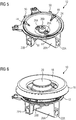
- FIG 2 illustrates a schematic perspective view of the base part 12 of the gas burner assembly 10 according to the first embodiment of the present invention.
- the base part 12 includes the gas inlet 22, the shell 24 with the open top side, the horizontal gas channel 28 and the pin 42.
- the injector 26 is arranged in the centre of the shell 24, which is the deepest position of the shell 24.
- the gas inlet 22 is arranged in the lower and outer portion of the shell 24.
- the horizontal gas channel 28 is interconnected between the gas inlet 22 and the centre of the shell 24.
- the pin 42 is provided for fixing and/or aligning the base part 12 on the bottom 46 of the gas cooking appliance.
- at least three pins 42 for fixing and/or aligning the base part 12 on the bottom of the gas cooking appliance are provided. In particular, said pins 42 extend downwards.
- the inner side of the shell 24 is formed as a circumferential surface of a truncated cone.
- the smooth surface allows that the shell 24 and the base part 12 are easy to clean. Further, the smooth surface around the injector 26 improves the composition and the flow conditions of the gas-air mixture within the shell 24.
- the shell 24 of the base part 12 includes pockets 44 in its upper portion for assembling and centring the burner crown 16, the outer burner cap 18 and the inner burner cap 20.
- the injector 26 withdraws fresh air on the top side of the work plate 48.
- the gas burner assembly 10 is a top-breather burner.
- the shell 24 does not have any opening arranged beneath said work plate 48. Thus, the injector 26 cannot suck air from the bottom side of the work plate 48.
- FIG 3 illustrates a schematic sectional side view of a base part 12 of the gas burner assembly 10 according to a second embodiment of the present invention.
- the base part 12 of the second embodiment is an integrated part of the work plate 48 of the gas cooking hob.
- the shell 24 of the base part 12 is a deformation in the work plate 48.
- the shell 24 of the base part 12 is obtained by embossing the sheet for the work plate 48 or other manufacturing techniques.
- the shell 24 of the base part 12 is obtained by forging the sheet for the work plate 48.
- the shell 24 of the base part 12 may be obtained by cold stamping the sheet for the work plate 48. This embodiment reduces the number of components of the gas burner assembly 10.
- the base part 12 includes the gas inlet 22, the shell 24 with the open top side, the horizontal gas channel 28 and the gas inlet 22.
- a gas supply tube 52 is inserted into the gas inlet 22.
- the injector 26 is arranged in the centre of the shell 24. Said centre is the deepest position of the shell 24.
- the gas inlet 22 is arranged in the lower portion of the shell 24.
- the horizontal gas channel 28 is interconnected between the gas inlet 22 and the centre of the shell 24.
- the shell 24 is formed as a circumferential surface of a truncated cone.
- the shell 24 of the base part 12 may be a separate component and fixed to the work plate 48 by suitable fastening elements.
- FIG 4 illustrates a schematic sectional side view of the gas burner assembly 10 according to a third embodiment of the present invention.
- the gas burner assembly 10 comprises the base part 12, the intermediate part 14, the burner crown 16, the outer burner cap 18 and the inner burner cap 20.
- the intermediate part 14 is arranged above the base part 12, while the burner crown 16 is arranged above the intermediate part 14.
- the outer burner cap 18 and the inner burner cap 20 are arranged on the burner crown 16.
- the outer burner cap 18 is formed as circular ring and inclined in radial direction, wherein the level of the outer burner cap 18 rises from inside to outside.
- the inner burner cap 20 is formed as circular disk.
- the base part 12 includes a first gas inlet 22A and a second gas inlet 22B, wherein only the first gas inlet 22A is explicitly shown in FIGF 4. Further, the base part 12 includes the shell 24, a first horizontal gas channel 28A and a second horizontal gas channel 28B. Three injectors 26A and 26B are arranged in the centre of the shell 24, wherein said centre is the deepest position of the shell 24. The injectors 26A and 26B are arranged in series. Two outer injectors 26A are supplied by the first horizontal gas channel 28A.
- the first horizontal gas channel 28A includes the first gas inlet 22A.
- the second horizontal gas channel 28B is arranged above and perpendicular to the first horizontal gas channel 28A.
- the second horizontal gas channel 28B includes the second gas inlet 22B and supplies an inner injector 26B.
- the gas channels 28A and 28B are only provided for delivering gas up to the level of the injectors 26A and 26B.
- External gas supply tubes are connectable to the gas inlets 22A and 22B.
- the both gas inlets 22A and 22B allow a separate control of the gas supplies for the inner injector 26B on the one hand and the outer injectors 26A on the other hand.
- the heat distribution above the gas burner assembly 10 may be adjusted.
- the intermediate part 14 is arranged above the base part 12.
- Three vertical Venturi pipes 30 are formed in the centre of said intermediate part 14, wherein each vertical Venturi pipe 30 is arranged above one of the injectors 26A and 26B.
- the burner crown 16 is arranged above the intermediate part 14.
- the prechamber 32 is formed between the intermediate part 14 and the burner crown 16. The height of said prechamber 32 increases radially, from inside to outside.
- the burner crown 16 includes the inner central chamber and the outer annular chamber connected to the prechamber 32.
- the burner crown 16 includes the plurality of inner and outer flame ports 40.
- the inner central chamber 34 is covered by the inner burner cap 20, while the outer annular chamber 36 is covered by the outer burner cap 18 formed as circular ring.
- the outer burner cap 18 and the inner burner cap 20 are arranged concentrically to each other. Preferably, the outer burner cap 18 and the inner burner cap 20 are arranged at the same level.
- FIG 5 illustrates a schematic perspective view of a base part 12 for the gas burner assembly 10 according to the third embodiment of the present invention.
- the injectors 26A and 26B are arranged in the centre of the shell 24.
- the centre is the deepest position of the shell 24.
- the gas inlets 22A and 22B are arranged in the lower portion of the shell 24 and arranged perpendicular to each other.
- the first gas inlet 22A on the right hand side in FIG 5 supplies the inner injector 26B, while the second gas inlet 22B on the left hand side in FIG 5 supplies the both outer injectors 26A.
- the shell 24 of the base part 12 includes pockets 44 in its upper portion for assembling and centring the burner crown 16, the outer burner cap 18 and/or the inner burner cap 20.
- the base part 12 includes screw holes 50 for fastening said base part on the work plate 48.
- FIG 6 illustrates a schematic perspective view of the gas burner assembly 10 according to the third embodiment of the present invention.
- the horizontal gas channels 28A and 28B with the gas inlets 22A and 22B are arranged in the lower portion of the shell 24.
- the horizontal gas channels 28A and 28B are arranged perpendicular to each other.
- the first horizontal gas channel 28A on the right hand side in FIG 6 supplies the inner injector 26B, while the second horizontal gas channel 28B on the left hand side in FIG 6 supplies the both outer injectors 26A.
- External gas supply tubes are connectable to the gas inlets 22A and 22B of the horizontal gas channels 28A and 28B, respectively.
- the both horizontal gas channels 28A and 28B allow a separate control of the gas supplies for the inner injector 26B on the one hand and the outer injectors 26A on the other hand.
- a fine tuning of the heat above the gas burner assembly 10 is possible. Further, the heat distribution above the gas burner assembly 10 may be adjusted.
Landscapes
- Engineering & Computer Science (AREA)
- Chemical & Material Sciences (AREA)
- Combustion & Propulsion (AREA)
- Mechanical Engineering (AREA)
- General Engineering & Computer Science (AREA)
- Gas Burners (AREA)
- Baking, Grill, Roasting (AREA)
Abstract
Description
- The present invention relates to a base part for a gas burner assembly. Further, the present invention relates to a gas burner assembly for a gas cooking appliance. Moreover, the present invention relates to a gas cooking appliance, in particular a domestic gas cooking hob.
- Conventional gas burner assemblies often include a base part acting as a holder for an injector. Usually, such base parts have a rectangular cross section and forming a kind of shell. However, such base parts are over-dimensioned and require a lot of material. Further the weight of the gas burner assembly with the base part is relative high. Moreover, the manufacturing of such base parts and gas burner assemblies is very complex.
- It is an object of the present invention to provide a base part for a gas burner assembly, which allows improved flow conditions of the gas-air mixture by low complexity.
- The object is achieved by the base for the gas burner assembly according to claim 1.
- According to the present invention a base part for a gas burner assembly of a gas cooking appliance, in particular of a domestic gas cooking hob, is provided, wherein:
- the base part includes a shell with an open top side,
- the base part includes and/or supports at least one injector arranged in the central and deepest position of the shell, and
- the inner side of the shell is formed as a circumferential surface of a truncated cone.
- The core of the present invention is the shape of the shell. The inner side of the shell is formed as a circumferential surface of a truncated cone, wherein the at least one injector is arranged in the deepest position of said shell. This allows a very smooth inner surface around the injector. In particular, the smooth surface around the injector improves the composition and the flow conditions of the gas-air mixture within the shell. Further, the smooth surface of the shell is easy to clean.
- In particular, the base part includes at least one gas inlet arranged beneath the shell, wherein preferably said gas inlet is arranged in a lower and/or outer portion of the base part.
- Preferably, the base part includes at least one gas channel, in particular a horizontal gas channel, interconnected between the gas inlet and the injector.
- Further, the inner side of the shell of the base part may be formed as smooth surface without any bends.
- Moreover, one or more pockets may be formed in the upper portion of the shell of the base part, wherein said pocket is provided for receiving an element of a burner crown.
- Additionally, the base part may include at least one pin, preferably at least two or at least three pins, for fixing and/or aligning said base part on a bottom of the gas cooking appliance. In particular, said pin or pins, respectively, extend downwards.
- According to another embodiment of the present invention, the shell of the base part is formed as an integrated part of a work plate of the gas cooking appliance. Preferably, the shell of the base part is embossed in the work plate of the gas cooking appliance. In particular, the shell of the base part is a deformation in the work plate of the gas cooking appliance. The shell of the base part may be obtained by forging the sheet for the work plate. Further, the shell of the base part may be obtained by cold stamping the sheet for the work plate. Alternatively, the shell of the base part may be a separate component fixed to the work plate by suitable fastening elements. The shell formed as integrated part of the work plate reduces the number of components of the gas burner assembly.
- Further, the present invention relates to a gas burner assembly for a gas cooking appliance, wherein said gas burner assembly comprises at least one base part mentioned above.
- In particular, the gas burner assembly comprises an intermediate part arranged above the base part, wherein preferably said intermediate part includes a vertical Venturi pipe in its central portion, so that the Venturi pipe is arranged above the injector.
- Additionally, the gas burner assembly may comprise a burner crown arranged above the intermediate part, wherein the burner crown includes a plurality of flame ports, and wherein preferably a prechamber is formed between the burner crown and the intermediate part.
- Further, the gas burner assembly may comprise at least one burner cap arranged above the burner crown and covering at least one chamber of said burner crown.
- According to a preferred embodiment, the burner crown includes an inner central chamber and an outer annular chamber, wherein the inner central chamber is covered by an inner burner cap and the outer annular chamber is covered by an outer burner cap.
- For example, a plurality of inner flame ports is formed in a circumferential side wall of the inner central chamber, wherein preferably the inner burner cap is formed as a circular disk.
- Additionally, a plurality of outer flame ports may be formed in an inner and/or outer circumferential side wall of the outer annular chamber, wherein preferably the outer burner cap is formed as a circular ring.
- According to the preferred embodiment, the plurality of outer flame ports is formed in the outer circumferential side wall of the outer annular chamber, wherein preferably the outer burner cap is formed as the circular ring and inclined in radial direction, so that the level of the outer burner cap rises from inside to outside.
- In particular, an upper side of the base part is open, so that the gas burner assembly takes primary fresh air from outside of the work plate.
- Further, the present invention relates to a gas cooking appliance, in particular a domestic gas cooking hob, wherein the gas cooking appliance comprises at least one gas burner assembly mentioned above.
- Novel and inventive features of the present invention are set forth in the appended claims.
- The present invention will be described in further detail with reference to the drawing, in which
- FIG 1
- illustrates a schematic sectional side view of a gas burner assembly according to a first embodiment of the present invention,
- FIG 2
- illustrates a schematic perspective view of a base part for the gas burner assembly according to the first embodiment of the present invention,
- FIG 3
- illustrates a schematic sectional side view of a base part of the gas burner assembly according to a second embodiment of the present invention,
- FIG 4
- illustrates a schematic sectional side view of the gas burner assembly according to a third embodiment of the present invention,
- FIG 5
- illustrates a schematic perspective view of a base part for the gas burner assembly according to the third embodiment of the present invention, and
- FIG 6
- illustrates a schematic perspective view of the gas burner assembly according to the third embodiment of the present invention.
-
FIG 1 illustrates a schematic sectional side view of agas burner assembly 10 according to a first embodiment of the present invention. Thegas burner assembly 10 is provided for a gas cooking appliance, in particular for a domestic gas cooking hob. - The
gas burner assembly 10 comprises abase part 12, anintermediate part 14, aburner crown 16, anouter burner cap 18 and aninner burner cap 20. Theintermediate part 14 is arranged above thebase part 12. In turn, theburner crown 16 is arranged above theintermediate part 14. Theouter burner cap 18 and theinner burner cap 20 are arranged on theburner crown 16. Theouter burner cap 18 is formed as a circular ring and inclined in radial direction, wherein the level of theouter burner cap 18 rises from inside to outside. Theinner burner cap 20 is formed as a circular disk. - The
base part 12 includes agas inlet 22, ashell 24 and ahorizontal gas channel 28. Thegas channel 28 is only provided for delivering gas up to the level of theinjector 26. An external gas supply tube is connectable to thegas inlet 22 forming the entrance of thegas channel 28. Theshell 24 has an open top side. Aninjector 26 is arranged in the centre of theshell 24, wherein said centre is the deepest position of theshell 24. Thegas inlet 22 is arranged in a lower and outer portion of thebase part 12. Thehorizontal gas channel 28 is interconnected between thegas inlet 22 and the centre of theshell 24, wherein theinjector 26 is arranged. Further, thebase part 12 includes apin 42 for fixing and/or aligning saidbase part 12 on a bottom 46 of the gas cooking appliance. In this example, saidpin 42 extends downwards. - The inner side of the
shell 24 is formed as a circumferential surface of a truncated cone. The inner surface of theshell 24 is very smooth. Said smooth surface allows that theshell 24 and thebase part 12 are easy to clean. In particular, the smooth surface around theinjector 26 improves the composition and the flow conditions of the gas-air mixture within theshell 24. - Optionally, also the outer side of the
shell 24 is formed as a circumferential surface of a truncated cone. In this case, the wall thickness of theshell 24 may be relative small resulting in low costs of material. This allows a light weight construction of thebase part 12. Further, this contributes to a lightweight and compact construction of thegas burner assembly 10. Theintermediate part 14 is arranged above thebase part 12. Avertical Venturi pipe 30 is formed in the centre of saidintermediate part 14. Thus, thevertical Venturi pipe 30 is arranged above theinjector 26. Theburner crown 16 is arranged above theintermediate part 14. Aprechamber 32 is formed between theintermediate part 14 and theburner crown 16. The height of saidprechamber 32 increases radially, from inside to outside. Theburner crown 16 includes an innercentral chamber 34 and an outerannular chamber 36 connected to theprechamber 32. - The
burner crown 16 includes a plurality ofinner flame ports 38 and a plurality ofouter flame ports 40. Theinner flame ports 38 are formed in a circumferential side wall of the innercentral chamber 34. Theouter flame ports 40 are formed in a circumferential side wall of the outerannular chamber 36. Thus, an outer ring of flames encloses the outerannular chamber 36, while an inner ring of flames is arranged between the innercentral chamber 34 and the outerannular chamber 36. - The inner
central chamber 34 is covered by theinner burner cap 20, while the outerannular chamber 36 is covered by theouter burner cap 18 formed as circular ring. Theouter burner cap 18 and theinner burner cap 20 are arranged concentrically to each other. Substantially, theouter burner cap 18 and theinner burner cap 20 are arranged at the same level. The outer ring of flames encloses theouter burner cap 18, while the inner ring of flames is arranged between theinner burner cap 20 and theouter burner cap 18. - The
gas burner assembly 10 is arranged within a cut-out of awork plate 48 of the gas cooking hob. Theintermediate part 14, theburner crown 16, theouter burner cap 18 and theinner burner cap 20 are arranged above thebase part 12 which in turn is arranged within the cut-out of thework plate 48. Thebase part 12 is substantially arranged beneath thework plate 48, theintermediate part 14 and theburner crown 16. Theouter burner cap 18 and theinner burner cap 20 are supported by thebase part 12. Theintermediate part 14 and theburner crown 16 are joined. Theouter burner cap 18 and theinner burner cap 20 are arranged above theburner crown 16. Theburner crown 16 is supported by thebase part 12 and fixed through the cut-out of thework plate 48. Thebase part 12 includes a number of screw holes 50 for fastening said base part on thework plate 48. In this example, thebase part 12 includes four screw holes 50. -
FIG 2 illustrates a schematic perspective view of thebase part 12 of thegas burner assembly 10 according to the first embodiment of the present invention. - The
base part 12 includes thegas inlet 22, theshell 24 with the open top side, thehorizontal gas channel 28 and thepin 42. Theinjector 26 is arranged in the centre of theshell 24, which is the deepest position of theshell 24. Thegas inlet 22 is arranged in the lower and outer portion of theshell 24. Thehorizontal gas channel 28 is interconnected between thegas inlet 22 and the centre of theshell 24. Thepin 42 is provided for fixing and/or aligning thebase part 12 on the bottom 46 of the gas cooking appliance. Preferably, at least threepins 42 for fixing and/or aligning thebase part 12 on the bottom of the gas cooking appliance are provided. In particular, said pins 42 extend downwards. - The inner side of the
shell 24 is formed as a circumferential surface of a truncated cone. The smooth surface allows that theshell 24 and thebase part 12 are easy to clean. Further, the smooth surface around theinjector 26 improves the composition and the flow conditions of the gas-air mixture within theshell 24. Moreover, theshell 24 of thebase part 12 includespockets 44 in its upper portion for assembling and centring theburner crown 16, theouter burner cap 18 and theinner burner cap 20. Theinjector 26 withdraws fresh air on the top side of thework plate 48. Thegas burner assembly 10 is a top-breather burner. In contrast, theshell 24 does not have any opening arranged beneath saidwork plate 48. Thus, theinjector 26 cannot suck air from the bottom side of thework plate 48. -
FIG 3 illustrates a schematic sectional side view of abase part 12 of thegas burner assembly 10 according to a second embodiment of the present invention. - The
base part 12 of the second embodiment is an integrated part of thework plate 48 of the gas cooking hob. Theshell 24 of thebase part 12 is a deformation in thework plate 48. Theshell 24 of thebase part 12 is obtained by embossing the sheet for thework plate 48 or other manufacturing techniques. For example, theshell 24 of thebase part 12 is obtained by forging the sheet for thework plate 48. Further, theshell 24 of thebase part 12 may be obtained by cold stamping the sheet for thework plate 48. This embodiment reduces the number of components of thegas burner assembly 10. - The
base part 12 includes thegas inlet 22, theshell 24 with the open top side, thehorizontal gas channel 28 and thegas inlet 22. Agas supply tube 52 is inserted into thegas inlet 22. Theinjector 26 is arranged in the centre of theshell 24. Said centre is the deepest position of theshell 24. Thegas inlet 22 is arranged in the lower portion of theshell 24. Thehorizontal gas channel 28 is interconnected between thegas inlet 22 and the centre of theshell 24. In this example, theshell 24 is formed as a circumferential surface of a truncated cone. Alternatively, theshell 24 of thebase part 12 may be a separate component and fixed to thework plate 48 by suitable fastening elements. -
FIG 4 illustrates a schematic sectional side view of thegas burner assembly 10 according to a third embodiment of the present invention. - The
gas burner assembly 10 comprises thebase part 12, theintermediate part 14, theburner crown 16, theouter burner cap 18 and theinner burner cap 20. Theintermediate part 14 is arranged above thebase part 12, while theburner crown 16 is arranged above theintermediate part 14. Theouter burner cap 18 and theinner burner cap 20 are arranged on theburner crown 16. Theouter burner cap 18 is formed as circular ring and inclined in radial direction, wherein the level of theouter burner cap 18 rises from inside to outside. Theinner burner cap 20 is formed as circular disk. - The
base part 12 includes afirst gas inlet 22A and asecond gas inlet 22B, wherein only thefirst gas inlet 22A is explicitly shown in FIGF 4. Further, thebase part 12 includes theshell 24, a firsthorizontal gas channel 28A and a secondhorizontal gas channel 28B. Threeinjectors shell 24, wherein said centre is the deepest position of theshell 24. Theinjectors outer injectors 26A are supplied by the firsthorizontal gas channel 28A. The firsthorizontal gas channel 28A includes thefirst gas inlet 22A. The secondhorizontal gas channel 28B is arranged above and perpendicular to the firsthorizontal gas channel 28A. The secondhorizontal gas channel 28B includes thesecond gas inlet 22B and supplies aninner injector 26B. Thegas channels injectors gas inlets gas inlets inner injector 26B on the one hand and theouter injectors 26A on the other hand. The heat distribution above thegas burner assembly 10 may be adjusted. - The
intermediate part 14 is arranged above thebase part 12. Threevertical Venturi pipes 30 are formed in the centre of saidintermediate part 14, wherein eachvertical Venturi pipe 30 is arranged above one of theinjectors burner crown 16 is arranged above theintermediate part 14. Theprechamber 32 is formed between theintermediate part 14 and theburner crown 16. The height of saidprechamber 32 increases radially, from inside to outside. Theburner crown 16 includes the inner central chamber and the outer annular chamber connected to theprechamber 32. Theburner crown 16 includes the plurality of inner andouter flame ports 40. The innercentral chamber 34 is covered by theinner burner cap 20, while the outerannular chamber 36 is covered by theouter burner cap 18 formed as circular ring. Theouter burner cap 18 and theinner burner cap 20 are arranged concentrically to each other. Preferably, theouter burner cap 18 and theinner burner cap 20 are arranged at the same level. -
FIG 5 illustrates a schematic perspective view of abase part 12 for thegas burner assembly 10 according to the third embodiment of the present invention. - The
injectors shell 24. The centre is the deepest position of theshell 24. Thegas inlets shell 24 and arranged perpendicular to each other. Thefirst gas inlet 22A on the right hand side inFIG 5 supplies theinner injector 26B, while thesecond gas inlet 22B on the left hand side inFIG 5 supplies the bothouter injectors 26A. - Further, the
shell 24 of thebase part 12 includespockets 44 in its upper portion for assembling and centring theburner crown 16, theouter burner cap 18 and/or theinner burner cap 20. Moreover, thebase part 12 includes screw holes 50 for fastening said base part on thework plate 48. -
FIG 6 illustrates a schematic perspective view of thegas burner assembly 10 according to the third embodiment of the present invention. - The
horizontal gas channels gas inlets shell 24. Thehorizontal gas channels horizontal gas channel 28A on the right hand side inFIG 6 supplies theinner injector 26B, while the secondhorizontal gas channel 28B on the left hand side inFIG 6 supplies the bothouter injectors 26A. External gas supply tubes are connectable to thegas inlets horizontal gas channels horizontal gas channels inner injector 26B on the one hand and theouter injectors 26A on the other hand. A fine tuning of the heat above thegas burner assembly 10 is possible. Further, the heat distribution above thegas burner assembly 10 may be adjusted. - Although illustrative embodiments of the present invention have been described herein with reference to the accompanying drawings, it is to be understood that the present invention is not limited to those precise embodiments, and that various other changes and modifications may be affected therein by one skilled in the art without departing from the scope or spirit of the invention. All such changes and modifications are intended to be included within the scope of the invention as defined by the appended claims.
-
- 10
- gas burner assembly
- 12
- base part
- 14
- intermediate part
- 16
- burner crown
- 18
- outer burner cap
- 20
- inner burner cap
- 22
- gas inlet
- 22A
- first gas inlet
- 22B
- second gas inlet
- 24
- shell
- 26
- injector
- 26A
- outer injector
- 26B
- inner injector
- 28
- horizontal gas channel
- 28A
- first horizontal gas channel
- 28B
- second horizontal gas channel
- 30
- vertical Venturi pipe
- 32
- prechamber
- 34
- inner central chamber
- 36
- outer annular chamber
- 38
- inner flame port
- 40
- outer flame port
- 42
- pin
- 44
- 46
- bottom sheet
- 48
- work plate
- 50
- screw hole
- 52
- gas supply tube
Claims (16)
- A base part (12) for a gas burner assembly (10) of a gas cooking appliance, in particular of a domestic gas cooking hob, wherein:- the base part (12) includes a shell (24) with an open top side,- the base part (12) includes and/or supports at least one injector (26; 26A, 26B) arranged in the central and deepest position of the shell (24), and- the inner side of the shell (24) is formed as a circumferential surface of a truncated cone.
- The base part according to claim 1,
characterised in that
the base part (12) includes at least one gas inlet (22; 22A, 22B) arranged beneath the shell (24), wherein preferably said gas inlet (22; 22A, 22B) is arranged in a lower and/or outer portion of the base part (12). - The base part according to claim 2,
characterised in that
the base part (12) includes at least one gas channel (28; 28A, 28B), in particular a horizontal gas channel (28; 28A, 28B), interconnected between the gas inlet (22; 22A, 22B) and the injector (26; 26A, 26B). - The base part according to any one of the preceding claims,
characterised in that
the inner side of the shell (24) of the base part (12) is formed as a smooth surface. - The base part according to any one of the preceding claims,
characterised in that
one or more pockets (44) are formed in the upper portion of the shell (24) of the base part (12), wherein said pocket (44) is provided for receiving an element of a burner crown (16) . - The base part according to any one of the preceding claims,
characterised in that
the base part (12) includes at least one pin (42), in particular at least two or at least three pins (42), for fixing and/or aligning said base part (12) on a bottom (46) of the gas cooking appliance, wherein preferably said pin (42) extends downwards. - The base part according to any one of the claims 1 to 5,
characterised in that
the shell (24) of the base part (12) is formed as an integrated part of a work plate (48) of the gas cooking appliance, wherein preferably the shell (24) of the base part (12) is embossed in the work plate (48) of the gas cooking appliance. - A gas burner assembly (10) comprising at least one base part (12) according to any one of the preceding claims,
characterised in that
the gas burner assembly (10) comprises an intermediate part (14) arranged above the base part (12), wherein preferably said intermediate part (14) includes a vertical Venturi pipe (30) in its central portion, so that the Venturi pipe (30) is arranged above the injector (26; 26A, 26B). - The gas burner assembly according to claim 8,
characterised in that
the gas burner assembly (10) comprises a burner crown (16) arranged above the intermediate part (14), wherein the burner crown (16) includes a plurality of flame ports (38, 40), and wherein preferably a prechamber (32) is formed between the burner crown (16) and the intermediate part (14). - The gas burner assembly according to claim 9,
characterised in that
the gas burner assembly (10) comprises at least one burner cap (18, 20) arranged above the burner crown (16) and covering at least one chamber (34, 36) of said burner crown (16). - The gas burner assembly according to claim 9 or 10,
characterised in that
the burner crown (16) includes an inner central chamber (34) and an outer annular chamber (36), wherein the inner central chamber (34) is covered by an inner burner cap (20) and the outer annular chamber (36) is covered by an outer burner cap (18) . - The gas burner assembly according to claim 11,
characterised in that
a plurality of inner flame ports (38) is formed in a circumferential side wall of the inner central chamber (34), wherein preferably the inner burner cap (20) is formed as a circular disk. - The gas burner assembly according to claim 11 or 12,
characterised in that
a plurality of outer flame ports (40) is formed in an inner and/or outer circumferential side wall of the outer annular chamber (36), wherein preferably the outer burner cap (18) is formed as a circular ring. - The gas burner assembly according to claim 13,
characterised in that
the plurality of outer flame ports (40) is formed in the outer circumferential side wall of the outer annular chamber (36), wherein preferably the outer burner cap (18) is formed as the circular ring and inclined in radial direction, so that the level of the outer burner cap (18) rises from inside to outside. - The gas burner assembly according to any one of the preceding claims,
characterised in that
an upper side of the base part (12) is open, so that the gas burner assembly takes primary fresh air from outside of the work plate (48). - A gas cooking appliance, in particular a domestic gas cooking hob, comprising at least one gas burner assembly (10) according to any one of the claims 8 to 15.
Priority Applications (2)
| Application Number | Priority Date | Filing Date | Title |
|---|---|---|---|
| ES19177836T ES2981446T3 (en) | 2019-06-03 | 2019-06-03 | Gas burner assembly |
| EP19177836.4A EP3748230B1 (en) | 2019-06-03 | 2019-06-03 | Gas burner assembly |
Applications Claiming Priority (1)
| Application Number | Priority Date | Filing Date | Title |
|---|---|---|---|
| EP19177836.4A EP3748230B1 (en) | 2019-06-03 | 2019-06-03 | Gas burner assembly |
Publications (2)
| Publication Number | Publication Date |
|---|---|
| EP3748230A1 true EP3748230A1 (en) | 2020-12-09 |
| EP3748230B1 EP3748230B1 (en) | 2024-03-20 |
Family
ID=66690217
Family Applications (1)
| Application Number | Title | Priority Date | Filing Date |
|---|---|---|---|
| EP19177836.4A Active EP3748230B1 (en) | 2019-06-03 | 2019-06-03 | Gas burner assembly |
Country Status (2)
| Country | Link |
|---|---|
| EP (1) | EP3748230B1 (en) |
| ES (1) | ES2981446T3 (en) |
Citations (6)
| Publication number | Priority date | Publication date | Assignee | Title |
|---|---|---|---|---|
| US6067978A (en) * | 1997-08-07 | 2000-05-30 | Schlosser; Erich J. | Outdoor cooking apparatus with improved auxiliary gas burner |
| EP1159565A1 (en) * | 1998-12-30 | 2001-12-05 | Ardempisirici Ve Isitici Cihazlar Sanavii A.S. | Deep drawn burner mechanism |
| EP1531304A2 (en) * | 2003-11-11 | 2005-05-18 | FAGOR, S.Coop | Triple crown gas burner for cooking hobs |
| EP1616132A1 (en) * | 2003-04-18 | 2006-01-18 | So.M.I. Press - Societa' Metalli Iniettati S.p.a. | Gas cooker burner of improved type |
| WO2007068659A1 (en) * | 2005-12-15 | 2007-06-21 | Arcelik Anonim Sirketi | A cooking device |
| EP2246619A1 (en) * | 2009-04-30 | 2010-11-03 | Electrolux Home Products Corporation N.V. | Vertical flame burner |
-
2019
- 2019-06-03 ES ES19177836T patent/ES2981446T3/en active Active
- 2019-06-03 EP EP19177836.4A patent/EP3748230B1/en active Active
Patent Citations (6)
| Publication number | Priority date | Publication date | Assignee | Title |
|---|---|---|---|---|
| US6067978A (en) * | 1997-08-07 | 2000-05-30 | Schlosser; Erich J. | Outdoor cooking apparatus with improved auxiliary gas burner |
| EP1159565A1 (en) * | 1998-12-30 | 2001-12-05 | Ardempisirici Ve Isitici Cihazlar Sanavii A.S. | Deep drawn burner mechanism |
| EP1616132A1 (en) * | 2003-04-18 | 2006-01-18 | So.M.I. Press - Societa' Metalli Iniettati S.p.a. | Gas cooker burner of improved type |
| EP1531304A2 (en) * | 2003-11-11 | 2005-05-18 | FAGOR, S.Coop | Triple crown gas burner for cooking hobs |
| WO2007068659A1 (en) * | 2005-12-15 | 2007-06-21 | Arcelik Anonim Sirketi | A cooking device |
| EP2246619A1 (en) * | 2009-04-30 | 2010-11-03 | Electrolux Home Products Corporation N.V. | Vertical flame burner |
Also Published As
| Publication number | Publication date |
|---|---|
| ES2981446T3 (en) | 2024-10-08 |
| EP3748230B1 (en) | 2024-03-20 |
Similar Documents
| Publication | Publication Date | Title |
|---|---|---|
| US9127838B2 (en) | Gas burner for cooking appliances | |
| CN102906501B (en) | There is the gas burner of multiple flame rings | |
| US10663164B2 (en) | Gas burner assembly | |
| MX2012014726A (en) | Gas burner with inward - facing flame. | |
| EP0903538A1 (en) | Gas burner | |
| EP3306192A1 (en) | Cap to change inner flame burner to vertical flame | |
| EP3385619B1 (en) | Burner for gas cooktop and gas cooktop | |
| US20190331337A1 (en) | Gas burner and hob comprising a gas burner | |
| CN111936791B (en) | Pan support, gas stove and method for producing a pan support | |
| US20180195718A1 (en) | Gas burner assembly for a gas cooking appliance | |
| US10451273B2 (en) | Gas burner assembly | |
| CN217356879U (en) | Combustor and gas-cooker with draw and penetrate hybrid system | |
| CN223499556U (en) | A stackable burner cap, burner and stove | |
| EP3748230B1 (en) | Gas burner assembly | |
| CN109959007B (en) | Burner fire cover for gas stove and burner using same | |
| CN205316318U (en) | Upper air inlet type stove burner | |
| CN109724082B (en) | High-efficiency burner | |
| EP4449019B1 (en) | Burner head for cooktop, burner, and cooktop | |
| CN113883520B (en) | Outer distributor and inner and outer fire assembly with same | |
| CN214406057U (en) | Fire distributor capable of inputting secondary air to center | |
| EP3980688B1 (en) | A burner assembly with a venturi element for gas cooking device | |
| CN210568430U (en) | Full-upper air inlet atmosphere and infrared mixed stove burner | |
| CN110848689B (en) | Upper air inlet combustor | |
| CN205560730U (en) | A cup body upper air intake type cooker burner | |
| CN111911922B (en) | Upward air intake burner |
Legal Events
| Date | Code | Title | Description |
|---|---|---|---|
| PUAI | Public reference made under article 153(3) epc to a published international application that has entered the european phase |
Free format text: ORIGINAL CODE: 0009012 |
|
| STAA | Information on the status of an ep patent application or granted ep patent |
Free format text: STATUS: THE APPLICATION HAS BEEN PUBLISHED |
|
| AK | Designated contracting states |
Kind code of ref document: A1 Designated state(s): AL AT BE BG CH CY CZ DE DK EE ES FI FR GB GR HR HU IE IS IT LI LT LU LV MC MK MT NL NO PL PT RO RS SE SI SK SM TR |
|
| AX | Request for extension of the european patent |
Extension state: BA ME |
|
| STAA | Information on the status of an ep patent application or granted ep patent |
Free format text: STATUS: REQUEST FOR EXAMINATION WAS MADE |
|
| 17P | Request for examination filed |
Effective date: 20210609 |
|
| RBV | Designated contracting states (corrected) |
Designated state(s): AL AT BE BG CH CY CZ DE DK EE ES FI FR GB GR HR HU IE IS IT LI LT LU LV MC MK MT NL NO PL PT RO RS SE SI SK SM TR |
|
| STAA | Information on the status of an ep patent application or granted ep patent |
Free format text: STATUS: EXAMINATION IS IN PROGRESS |
|
| 17Q | First examination report despatched |
Effective date: 20211117 |
|
| GRAP | Despatch of communication of intention to grant a patent |
Free format text: ORIGINAL CODE: EPIDOSNIGR1 |
|
| STAA | Information on the status of an ep patent application or granted ep patent |
Free format text: STATUS: GRANT OF PATENT IS INTENDED |
|
| INTG | Intention to grant announced |
Effective date: 20231011 |
|
| P01 | Opt-out of the competence of the unified patent court (upc) registered |
Effective date: 20231108 |
|
| GRAS | Grant fee paid |
Free format text: ORIGINAL CODE: EPIDOSNIGR3 |
|
| GRAA | (expected) grant |
Free format text: ORIGINAL CODE: 0009210 |
|
| STAA | Information on the status of an ep patent application or granted ep patent |
Free format text: STATUS: THE PATENT HAS BEEN GRANTED |
|
| AK | Designated contracting states |
Kind code of ref document: B1 Designated state(s): AL AT BE BG CH CY CZ DE DK EE ES FI FR GB GR HR HU IE IS IT LI LT LU LV MC MK MT NL NO PL PT RO RS SE SI SK SM TR |
|
| REG | Reference to a national code |
Ref country code: GB Ref legal event code: FG4D |
|
| REG | Reference to a national code |
Ref country code: CH Ref legal event code: EP |
|
| REG | Reference to a national code |
Ref country code: IE Ref legal event code: FG4D |
|
| REG | Reference to a national code |
Ref country code: DE Ref legal event code: R096 Ref document number: 602019048499 Country of ref document: DE |
|
| PG25 | Lapsed in a contracting state [announced via postgrant information from national office to epo] |
Ref country code: LT Free format text: LAPSE BECAUSE OF FAILURE TO SUBMIT A TRANSLATION OF THE DESCRIPTION OR TO PAY THE FEE WITHIN THE PRESCRIBED TIME-LIMIT Effective date: 20240320 |
|
| REG | Reference to a national code |
Ref country code: LT Ref legal event code: MG9D |
|
| PG25 | Lapsed in a contracting state [announced via postgrant information from national office to epo] |
Ref country code: GR Free format text: LAPSE BECAUSE OF FAILURE TO SUBMIT A TRANSLATION OF THE DESCRIPTION OR TO PAY THE FEE WITHIN THE PRESCRIBED TIME-LIMIT Effective date: 20240621 |
|
| PG25 | Lapsed in a contracting state [announced via postgrant information from national office to epo] |
Ref country code: RS Free format text: LAPSE BECAUSE OF FAILURE TO SUBMIT A TRANSLATION OF THE DESCRIPTION OR TO PAY THE FEE WITHIN THE PRESCRIBED TIME-LIMIT Effective date: 20240620 Ref country code: HR Free format text: LAPSE BECAUSE OF FAILURE TO SUBMIT A TRANSLATION OF THE DESCRIPTION OR TO PAY THE FEE WITHIN THE PRESCRIBED TIME-LIMIT Effective date: 20240320 |
|
| REG | Reference to a national code |
Ref country code: NL Ref legal event code: MP Effective date: 20240320 |
|
| PG25 | Lapsed in a contracting state [announced via postgrant information from national office to epo] |
Ref country code: RS Free format text: LAPSE BECAUSE OF FAILURE TO SUBMIT A TRANSLATION OF THE DESCRIPTION OR TO PAY THE FEE WITHIN THE PRESCRIBED TIME-LIMIT Effective date: 20240620 Ref country code: NO Free format text: LAPSE BECAUSE OF FAILURE TO SUBMIT A TRANSLATION OF THE DESCRIPTION OR TO PAY THE FEE WITHIN THE PRESCRIBED TIME-LIMIT Effective date: 20240620 Ref country code: LT Free format text: LAPSE BECAUSE OF FAILURE TO SUBMIT A TRANSLATION OF THE DESCRIPTION OR TO PAY THE FEE WITHIN THE PRESCRIBED TIME-LIMIT Effective date: 20240320 Ref country code: HR Free format text: LAPSE BECAUSE OF FAILURE TO SUBMIT A TRANSLATION OF THE DESCRIPTION OR TO PAY THE FEE WITHIN THE PRESCRIBED TIME-LIMIT Effective date: 20240320 Ref country code: GR Free format text: LAPSE BECAUSE OF FAILURE TO SUBMIT A TRANSLATION OF THE DESCRIPTION OR TO PAY THE FEE WITHIN THE PRESCRIBED TIME-LIMIT Effective date: 20240621 Ref country code: FI Free format text: LAPSE BECAUSE OF FAILURE TO SUBMIT A TRANSLATION OF THE DESCRIPTION OR TO PAY THE FEE WITHIN THE PRESCRIBED TIME-LIMIT Effective date: 20240320 Ref country code: BG Free format text: LAPSE BECAUSE OF FAILURE TO SUBMIT A TRANSLATION OF THE DESCRIPTION OR TO PAY THE FEE WITHIN THE PRESCRIBED TIME-LIMIT Effective date: 20240320 |
|
| REG | Reference to a national code |
Ref country code: AT Ref legal event code: MK05 Ref document number: 1668108 Country of ref document: AT Kind code of ref document: T Effective date: 20240320 |
|
| PG25 | Lapsed in a contracting state [announced via postgrant information from national office to epo] |
Ref country code: SE Free format text: LAPSE BECAUSE OF FAILURE TO SUBMIT A TRANSLATION OF THE DESCRIPTION OR TO PAY THE FEE WITHIN THE PRESCRIBED TIME-LIMIT Effective date: 20240320 Ref country code: LV Free format text: LAPSE BECAUSE OF FAILURE TO SUBMIT A TRANSLATION OF THE DESCRIPTION OR TO PAY THE FEE WITHIN THE PRESCRIBED TIME-LIMIT Effective date: 20240320 |
|
| PG25 | Lapsed in a contracting state [announced via postgrant information from national office to epo] |
Ref country code: NL Free format text: LAPSE BECAUSE OF FAILURE TO SUBMIT A TRANSLATION OF THE DESCRIPTION OR TO PAY THE FEE WITHIN THE PRESCRIBED TIME-LIMIT Effective date: 20240320 |
|
| PG25 | Lapsed in a contracting state [announced via postgrant information from national office to epo] |
Ref country code: NL Free format text: LAPSE BECAUSE OF FAILURE TO SUBMIT A TRANSLATION OF THE DESCRIPTION OR TO PAY THE FEE WITHIN THE PRESCRIBED TIME-LIMIT Effective date: 20240320 |
|
| PG25 | Lapsed in a contracting state [announced via postgrant information from national office to epo] |
Ref country code: IS Free format text: LAPSE BECAUSE OF FAILURE TO SUBMIT A TRANSLATION OF THE DESCRIPTION OR TO PAY THE FEE WITHIN THE PRESCRIBED TIME-LIMIT Effective date: 20240720 |
|
| REG | Reference to a national code |
Ref country code: ES Ref legal event code: FG2A Ref document number: 2981446 Country of ref document: ES Kind code of ref document: T3 Effective date: 20241008 |
|
| PG25 | Lapsed in a contracting state [announced via postgrant information from national office to epo] |
Ref country code: PT Free format text: LAPSE BECAUSE OF FAILURE TO SUBMIT A TRANSLATION OF THE DESCRIPTION OR TO PAY THE FEE WITHIN THE PRESCRIBED TIME-LIMIT Effective date: 20240722 Ref country code: SM Free format text: LAPSE BECAUSE OF FAILURE TO SUBMIT A TRANSLATION OF THE DESCRIPTION OR TO PAY THE FEE WITHIN THE PRESCRIBED TIME-LIMIT Effective date: 20240320 |
|
| PG25 | Lapsed in a contracting state [announced via postgrant information from national office to epo] |
Ref country code: CZ Free format text: LAPSE BECAUSE OF FAILURE TO SUBMIT A TRANSLATION OF THE DESCRIPTION OR TO PAY THE FEE WITHIN THE PRESCRIBED TIME-LIMIT Effective date: 20240320 Ref country code: EE Free format text: LAPSE BECAUSE OF FAILURE TO SUBMIT A TRANSLATION OF THE DESCRIPTION OR TO PAY THE FEE WITHIN THE PRESCRIBED TIME-LIMIT Effective date: 20240320 |
|
| PG25 | Lapsed in a contracting state [announced via postgrant information from national office to epo] |
Ref country code: AT Free format text: LAPSE BECAUSE OF FAILURE TO SUBMIT A TRANSLATION OF THE DESCRIPTION OR TO PAY THE FEE WITHIN THE PRESCRIBED TIME-LIMIT Effective date: 20240320 |
|
| PG25 | Lapsed in a contracting state [announced via postgrant information from national office to epo] |
Ref country code: PL Free format text: LAPSE BECAUSE OF FAILURE TO SUBMIT A TRANSLATION OF THE DESCRIPTION OR TO PAY THE FEE WITHIN THE PRESCRIBED TIME-LIMIT Effective date: 20240320 |
|
| PG25 | Lapsed in a contracting state [announced via postgrant information from national office to epo] |
Ref country code: SK Free format text: LAPSE BECAUSE OF FAILURE TO SUBMIT A TRANSLATION OF THE DESCRIPTION OR TO PAY THE FEE WITHIN THE PRESCRIBED TIME-LIMIT Effective date: 20240320 |
|
| PG25 | Lapsed in a contracting state [announced via postgrant information from national office to epo] |
Ref country code: SM Free format text: LAPSE BECAUSE OF FAILURE TO SUBMIT A TRANSLATION OF THE DESCRIPTION OR TO PAY THE FEE WITHIN THE PRESCRIBED TIME-LIMIT Effective date: 20240320 Ref country code: SK Free format text: LAPSE BECAUSE OF FAILURE TO SUBMIT A TRANSLATION OF THE DESCRIPTION OR TO PAY THE FEE WITHIN THE PRESCRIBED TIME-LIMIT Effective date: 20240320 Ref country code: RO Free format text: LAPSE BECAUSE OF FAILURE TO SUBMIT A TRANSLATION OF THE DESCRIPTION OR TO PAY THE FEE WITHIN THE PRESCRIBED TIME-LIMIT Effective date: 20240320 Ref country code: PT Free format text: LAPSE BECAUSE OF FAILURE TO SUBMIT A TRANSLATION OF THE DESCRIPTION OR TO PAY THE FEE WITHIN THE PRESCRIBED TIME-LIMIT Effective date: 20240722 Ref country code: PL Free format text: LAPSE BECAUSE OF FAILURE TO SUBMIT A TRANSLATION OF THE DESCRIPTION OR TO PAY THE FEE WITHIN THE PRESCRIBED TIME-LIMIT Effective date: 20240320 Ref country code: IS Free format text: LAPSE BECAUSE OF FAILURE TO SUBMIT A TRANSLATION OF THE DESCRIPTION OR TO PAY THE FEE WITHIN THE PRESCRIBED TIME-LIMIT Effective date: 20240720 Ref country code: EE Free format text: LAPSE BECAUSE OF FAILURE TO SUBMIT A TRANSLATION OF THE DESCRIPTION OR TO PAY THE FEE WITHIN THE PRESCRIBED TIME-LIMIT Effective date: 20240320 Ref country code: CZ Free format text: LAPSE BECAUSE OF FAILURE TO SUBMIT A TRANSLATION OF THE DESCRIPTION OR TO PAY THE FEE WITHIN THE PRESCRIBED TIME-LIMIT Effective date: 20240320 Ref country code: AT Free format text: LAPSE BECAUSE OF FAILURE TO SUBMIT A TRANSLATION OF THE DESCRIPTION OR TO PAY THE FEE WITHIN THE PRESCRIBED TIME-LIMIT Effective date: 20240320 |
|
| REG | Reference to a national code |
Ref country code: DE Ref legal event code: R097 Ref document number: 602019048499 Country of ref document: DE |
|
| REG | Reference to a national code |
Ref country code: DE Ref legal event code: R119 Ref document number: 602019048499 Country of ref document: DE |
|
| PG25 | Lapsed in a contracting state [announced via postgrant information from national office to epo] |
Ref country code: DK Free format text: LAPSE BECAUSE OF FAILURE TO SUBMIT A TRANSLATION OF THE DESCRIPTION OR TO PAY THE FEE WITHIN THE PRESCRIBED TIME-LIMIT Effective date: 20240320 |
|
| PLBE | No opposition filed within time limit |
Free format text: ORIGINAL CODE: 0009261 |
|
| STAA | Information on the status of an ep patent application or granted ep patent |
Free format text: STATUS: NO OPPOSITION FILED WITHIN TIME LIMIT |
|
| PG25 | Lapsed in a contracting state [announced via postgrant information from national office to epo] |
Ref country code: DK Free format text: LAPSE BECAUSE OF FAILURE TO SUBMIT A TRANSLATION OF THE DESCRIPTION OR TO PAY THE FEE WITHIN THE PRESCRIBED TIME-LIMIT Effective date: 20240320 Ref country code: MC Free format text: LAPSE BECAUSE OF FAILURE TO SUBMIT A TRANSLATION OF THE DESCRIPTION OR TO PAY THE FEE WITHIN THE PRESCRIBED TIME-LIMIT Effective date: 20240320 |
|
| REG | Reference to a national code |
Ref country code: CH Ref legal event code: PL |
|
| PG25 | Lapsed in a contracting state [announced via postgrant information from national office to epo] |
Ref country code: LU Free format text: LAPSE BECAUSE OF NON-PAYMENT OF DUE FEES Effective date: 20240603 |
|
| 26N | No opposition filed |
Effective date: 20241223 |
|
| PG25 | Lapsed in a contracting state [announced via postgrant information from national office to epo] |
Ref country code: DE Free format text: LAPSE BECAUSE OF NON-PAYMENT OF DUE FEES Effective date: 20250101 |
|
| PG25 | Lapsed in a contracting state [announced via postgrant information from national office to epo] |
Ref country code: IE Free format text: LAPSE BECAUSE OF NON-PAYMENT OF DUE FEES Effective date: 20240603 |
|
| PG25 | Lapsed in a contracting state [announced via postgrant information from national office to epo] |
Ref country code: SI Free format text: LAPSE BECAUSE OF FAILURE TO SUBMIT A TRANSLATION OF THE DESCRIPTION OR TO PAY THE FEE WITHIN THE PRESCRIBED TIME-LIMIT Effective date: 20240320 Ref country code: BE Free format text: LAPSE BECAUSE OF NON-PAYMENT OF DUE FEES Effective date: 20240630 Ref country code: CH Free format text: LAPSE BECAUSE OF NON-PAYMENT OF DUE FEES Effective date: 20240630 |
|
| REG | Reference to a national code |
Ref country code: BE Ref legal event code: MM Effective date: 20240630 |
|
| PGFP | Annual fee paid to national office [announced via postgrant information from national office to epo] |
Ref country code: GB Payment date: 20250617 Year of fee payment: 7 |
|
| PGFP | Annual fee paid to national office [announced via postgrant information from national office to epo] |
Ref country code: FR Payment date: 20250624 Year of fee payment: 7 |
|
| PG25 | Lapsed in a contracting state [announced via postgrant information from national office to epo] |
Ref country code: CY Free format text: LAPSE BECAUSE OF FAILURE TO SUBMIT A TRANSLATION OF THE DESCRIPTION OR TO PAY THE FEE WITHIN THE PRESCRIBED TIME-LIMIT; INVALID AB INITIO Effective date: 20190603 |
|
| PGFP | Annual fee paid to national office [announced via postgrant information from national office to epo] |
Ref country code: ES Payment date: 20250710 Year of fee payment: 7 |
|
| PGFP | Annual fee paid to national office [announced via postgrant information from national office to epo] |
Ref country code: IT Payment date: 20250623 Year of fee payment: 7 |
|
| PG25 | Lapsed in a contracting state [announced via postgrant information from national office to epo] |
Ref country code: HU Free format text: LAPSE BECAUSE OF FAILURE TO SUBMIT A TRANSLATION OF THE DESCRIPTION OR TO PAY THE FEE WITHIN THE PRESCRIBED TIME-LIMIT; INVALID AB INITIO Effective date: 20190603 |