EP3748211B1 - Retaining assembly for a gas turbine engine - Google Patents
Retaining assembly for a gas turbine engine Download PDFInfo
- Publication number
- EP3748211B1 EP3748211B1 EP20153210.8A EP20153210A EP3748211B1 EP 3748211 B1 EP3748211 B1 EP 3748211B1 EP 20153210 A EP20153210 A EP 20153210A EP 3748211 B1 EP3748211 B1 EP 3748211B1
- Authority
- EP
- European Patent Office
- Prior art keywords
- bracket
- assembly
- tube
- clamp
- retention component
- Prior art date
- Legal status (The legal status is an assumption and is not a legal conclusion. Google has not performed a legal analysis and makes no representation as to the accuracy of the status listed.)
- Active
Links
Images



Classifications
-
- F—MECHANICAL ENGINEERING; LIGHTING; HEATING; WEAPONS; BLASTING
- F16—ENGINEERING ELEMENTS AND UNITS; GENERAL MEASURES FOR PRODUCING AND MAINTAINING EFFECTIVE FUNCTIONING OF MACHINES OR INSTALLATIONS; THERMAL INSULATION IN GENERAL
- F16L—PIPES; JOINTS OR FITTINGS FOR PIPES; SUPPORTS FOR PIPES, CABLES OR PROTECTIVE TUBING; MEANS FOR THERMAL INSULATION IN GENERAL
- F16L23/00—Flanged joints
- F16L23/04—Flanged joints the flanges being connected by members tensioned in the radial plane
- F16L23/08—Flanged joints the flanges being connected by members tensioned in the radial plane connection by tangentially arranged pin and nut
-
- F—MECHANICAL ENGINEERING; LIGHTING; HEATING; WEAPONS; BLASTING
- F01—MACHINES OR ENGINES IN GENERAL; ENGINE PLANTS IN GENERAL; STEAM ENGINES
- F01D—NON-POSITIVE DISPLACEMENT MACHINES OR ENGINES, e.g. STEAM TURBINES
- F01D25/00—Component parts, details, or accessories, not provided for in, or of interest apart from, other groups
- F01D25/18—Lubricating arrangements
-
- F—MECHANICAL ENGINEERING; LIGHTING; HEATING; WEAPONS; BLASTING
- F02—COMBUSTION ENGINES; HOT-GAS OR COMBUSTION-PRODUCT ENGINE PLANTS
- F02C—GAS-TURBINE PLANTS; AIR INTAKES FOR JET-PROPULSION PLANTS; CONTROLLING FUEL SUPPLY IN AIR-BREATHING JET-PROPULSION PLANTS
- F02C6/00—Plural gas-turbine plants; Combinations of gas-turbine plants with other apparatus; Adaptations of gas-turbine plants for special use
- F02C6/04—Gas-turbine plants providing heated or pressurised working fluid for other apparatus, e.g. without mechanical power output
- F02C6/06—Gas-turbine plants providing heated or pressurised working fluid for other apparatus, e.g. without mechanical power output providing compressed gas
- F02C6/08—Gas-turbine plants providing heated or pressurised working fluid for other apparatus, e.g. without mechanical power output providing compressed gas the gas being bled from the gas-turbine compressor
-
- F—MECHANICAL ENGINEERING; LIGHTING; HEATING; WEAPONS; BLASTING
- F02—COMBUSTION ENGINES; HOT-GAS OR COMBUSTION-PRODUCT ENGINE PLANTS
- F02C—GAS-TURBINE PLANTS; AIR INTAKES FOR JET-PROPULSION PLANTS; CONTROLLING FUEL SUPPLY IN AIR-BREATHING JET-PROPULSION PLANTS
- F02C7/00—Features, components parts, details or accessories, not provided for in, or of interest apart form groups F02C1/00 - F02C6/00; Air intakes for jet-propulsion plants
-
- F—MECHANICAL ENGINEERING; LIGHTING; HEATING; WEAPONS; BLASTING
- F02—COMBUSTION ENGINES; HOT-GAS OR COMBUSTION-PRODUCT ENGINE PLANTS
- F02C—GAS-TURBINE PLANTS; AIR INTAKES FOR JET-PROPULSION PLANTS; CONTROLLING FUEL SUPPLY IN AIR-BREATHING JET-PROPULSION PLANTS
- F02C7/00—Features, components parts, details or accessories, not provided for in, or of interest apart form groups F02C1/00 - F02C6/00; Air intakes for jet-propulsion plants
- F02C7/22—Fuel supply systems
- F02C7/222—Fuel flow conduits, e.g. manifolds
-
- F—MECHANICAL ENGINEERING; LIGHTING; HEATING; WEAPONS; BLASTING
- F02—COMBUSTION ENGINES; HOT-GAS OR COMBUSTION-PRODUCT ENGINE PLANTS
- F02K—JET-PROPULSION PLANTS
- F02K1/00—Plants characterised by the form or arrangement of the jet pipe or nozzle; Jet pipes or nozzles peculiar thereto
- F02K1/78—Other construction of jet pipes
- F02K1/80—Couplings or connections
-
- F—MECHANICAL ENGINEERING; LIGHTING; HEATING; WEAPONS; BLASTING
- F16—ENGINEERING ELEMENTS AND UNITS; GENERAL MEASURES FOR PRODUCING AND MAINTAINING EFFECTIVE FUNCTIONING OF MACHINES OR INSTALLATIONS; THERMAL INSULATION IN GENERAL
- F16L—PIPES; JOINTS OR FITTINGS FOR PIPES; SUPPORTS FOR PIPES, CABLES OR PROTECTIVE TUBING; MEANS FOR THERMAL INSULATION IN GENERAL
- F16L1/00—Laying or reclaiming pipes; Repairing or joining pipes on or under water
- F16L1/024—Laying or reclaiming pipes on land, e.g. above the ground
- F16L1/06—Accessories therefor, e.g. anchors
-
- F—MECHANICAL ENGINEERING; LIGHTING; HEATING; WEAPONS; BLASTING
- F05—INDEXING SCHEMES RELATING TO ENGINES OR PUMPS IN VARIOUS SUBCLASSES OF CLASSES F01-F04
- F05D—INDEXING SCHEME FOR ASPECTS RELATING TO NON-POSITIVE-DISPLACEMENT MACHINES OR ENGINES, GAS-TURBINES OR JET-PROPULSION PLANTS
- F05D2220/00—Application
- F05D2220/30—Application in turbines
- F05D2220/32—Application in turbines in gas turbines
-
- F—MECHANICAL ENGINEERING; LIGHTING; HEATING; WEAPONS; BLASTING
- F05—INDEXING SCHEMES RELATING TO ENGINES OR PUMPS IN VARIOUS SUBCLASSES OF CLASSES F01-F04
- F05D—INDEXING SCHEME FOR ASPECTS RELATING TO NON-POSITIVE-DISPLACEMENT MACHINES OR ENGINES, GAS-TURBINES OR JET-PROPULSION PLANTS
- F05D2260/00—Function
- F05D2260/30—Retaining components in desired mutual position
-
- F—MECHANICAL ENGINEERING; LIGHTING; HEATING; WEAPONS; BLASTING
- F05—INDEXING SCHEMES RELATING TO ENGINES OR PUMPS IN VARIOUS SUBCLASSES OF CLASSES F01-F04
- F05D—INDEXING SCHEME FOR ASPECTS RELATING TO NON-POSITIVE-DISPLACEMENT MACHINES OR ENGINES, GAS-TURBINES OR JET-PROPULSION PLANTS
- F05D2260/00—Function
- F05D2260/30—Retaining components in desired mutual position
- F05D2260/39—Retaining components in desired mutual position by a V-shaped ring to join the flanges of two cylindrical sections, e.g. casing sections of a turbocharger
Definitions
- the present disclosure relates to aircraft propulsion systems, and more particularly, to a retaining assembly for a clamp.
- Jet aircraft propulsion systems such as those that power modern commercial and military aircraft, include a variety of external components that support and/or connect one tube assembly to another. During maintenance operations of a gas turbine engine, the external components may be misplaced, lost, or dropped.
- US 3489434 A1 describes a power actuated coupling with clamps mounted on an annular spring plate which flex when the clamps grip a pipe flange of a conduit. The clamps lock over the center and the flexed spring plate thus provides clamping pressure.
- Each clamp includes an arm arranged to flex when in clamping position, and a force sensing mechanism for sensing additional flexure if the coupling tends to separate from the pipe flange.
- US 2011/0253675 A1 describes a three-phase vacuum interrupter switch assembly for power distribution systems that comprises an outer case having at least one window, a plurality of internal disconnect switch assemblies, and a plurality of vacuum interrupter bottle switch assemblies within the case.
- DE 102012213640 A1 describes a pipe plug-in device for connecting two pipes by inserting one end of one pipe into one end of another pipe.
- US 5226231 A1 describes a tool for joining plastic pipe and fittings that provide for a quarter turn rotation of a pipe fitting while simultaneously pulling a free end of a longitudinally aligned pipe section into the fitting.
- the tool includes an inner ring that slips over a free end of a pipe section and is secured thereto by inwardly directed mounting screws, and an outer ring coaxially circumposed about, and rotatably connected to, the inner ring.
- GB 2311480 A describes a clamping assembly which has a clamp member which can be positioned at different pitch angles with respect to the top of a worktable.
- US 2015/0174706 A1 describes an apparatus for aligning sections of pipe that includes a first clamp member and a second clamp member coupled with the first clamp member.
- the first and second clamp members each include a first clamp jaw and a second clamp jaw longitudinally spaced from the first clamp jaw.
- EP 0429925 A2 describes a tool used in joining the adjacent ends of pipes and the like including a structural arrangement which is capable of moving the ends of the members to be joined towards and away from each other, transversely in relation to each other for alignment and adjusting the angular relation of the adjacent ends to accurately, positively, quickly and easily position adjacent ends of pipe members and the like in optimum desired relation for joining the members by welding.
- the second end and the clevis may define a fulcrum, and the bracket assembly may be able to rotate about the fulcrum.
- the clevis and the second end define a fulcrum.
- the clamping band may able to rotate via the bracket assembly about the fulcrum.
- the retention component may comprise at least one of a worm gear or a fastener configured to either loosen or tighten the retention component.
- the retention component may comprise at least one of a chain or a band/strap.
- a retaining assembly configured retain a clamp assembly to a fixed tubing structure during maintenance operations of a gas turbine engine.
- the retaining assembly may include a retention component configured to retain the clamp assembly to a tube assembly.
- the retaining assembly includes a bracket assembly configured to couple the retention component to a clamp.
- the clamp assembly includes the retaining assembly and is configured to connect a first tube to a second tube. Accordingly, a clamp assembly having a retaining assembly, as disclosed herein, can reduce or eliminate the possibility of misplacing or dropping a clamp assembly during maintenance operations of a gas turbine engine.
- FIG. 1 schematically illustrates a gas turbine engine 20.
- the gas turbine engine 20 is disclosed herein as a two-spool turbofan that generally incorporates a fan section 22, a compressor section 24, a combustor section 26 and a turbine section 28.
- the fan section 22 drives air along a bypass flow path B in a bypass duct defined within a nacelle 15, while the compressor section 24 drives air along a core or primary flow path C for compression and communication into the combustor section 26 and then expansion through the turbine section 28.
- FIG. 1 schematically illustrates a gas turbine engine 20.
- the gas turbine engine 20 is disclosed herein as a two-spool turbofan that generally incorporates a fan section 22, a compressor section 24, a combustor section 26 and a turbine section 28.
- the fan section 22 drives air along a bypass flow path B in a bypass duct defined within a nacelle 15, while the compressor section 24 drives air along a core or primary flow path C for compression and communication into the combustor section 26 and then expansion
- the gas turbine engine 20 generally includes a low speed spool 30 and a high speed spool 32 mounted for rotation about an engine central longitudinal axis A relative to an engine static structure 36 via several bearing systems 38. It should be understood that various bearing systems at various locations may alternatively or additionally be provided and the location of the several bearing systems 38 may be varied as appropriate to the application.
- the low speed spool 30 generally includes an inner shaft 40 that interconnects a fan 42, a low pressure compressor 44 and a low pressure turbine 46.
- the inner shaft 40 is connected to the fan 42 through a speed change mechanism, which in this gas turbine engine 20 is illustrated as a fan drive gear system 48 configured to drive the fan 42 at a lower speed than the low speed spool 30.
- the high speed spool 32 includes an outer shaft 50 that interconnects a high pressure compressor 52 and a high pressure turbine 54.
- a combustor 56 is arranged in the gas turbine engine 20 between the high pressure compressor 52 and the high pressure turbine 54.
- a mid-turbine frame 57 of the engine static structure 36 is arranged generally between the high pressure turbine 54 and the low pressure turbine 46 and may include airfoils 59 in the core flow path C for guiding the flow into the low pressure turbine 46.
- the mid-turbine frame 57 further supports the several bearing systems 38 in the turbine section 28.
- the inner shaft 40 and the outer shaft 50 are concentric and rotate via the several bearing systems 38 about the engine central longitudinal axis A, which is collinear with longitudinal axes of the inner shaft 40 and the outer shaft 50.
- the air in the core flow path C is compressed by the low pressure compressor 44 and then the high pressure compressor 52, mixed and burned with fuel in the combustor 56, and then expanded over the high pressure turbine 54 and low pressure turbine 46.
- the low pressure turbine 46 and the high pressure turbine 54 rotationally drive the respective low speed spool 30 and the high speed spool 32 in response to the expansion.
- each of the positions of the fan section 22, the compressor section 24, the combustor section 26, the turbine section 28, and the fan drive gear system 48 may be varied.
- the fan drive gear system 48 may be located aft of the combustor section 26 or even aft of the turbine section 28, and the fan section 22 may be positioned forward or aft of the location of the fan drive gear system 48.
- Tubing system 200 may provide various fluids (e.g., air, oil, fuel, hydraulic, etc) to components in various compartments in gas turbine engine 100 in FIG. 1 .
- fluids e.g., air, oil, fuel, hydraulic, etc
- tubing system 200 may provide bleed air from the compressor section (44, 52) to the nacelle.
- a tubing system 200 may include a first tube 210 having a first tube end 212 and a second tube 220 having a second tube end 222.
- the first tube end 212 may be coupled to the second tube end 222 by a clamp assembly 230.
- the clamp assembly 230 may include a sleeve 240 having a semi-annular portion 242 and a clevis 244.
- the semi-annular portion 242 of the sleeve 240 may be coupled to the first tube 210 on an outer surface 214 of the first tube 210.
- the connection of the sleeve 240 to the first tube 210 may be fixed or removable.
- the sleeve 240 is fixedly connected to the first tube 210 by brazing, or any other method known in the art. In various embodiments, the sleeve 240 is connected to the first tube 210 by a retaining component that retains the clamp assembly in place but may be removable from the first tube 210.
- the clamp assembly 230 further includes a bracket assembly 250 having a first bracket end 252 and a second bracket end 254.
- the bracket assembly may be a single machined piece or multiple sheet metal brackets.
- the second bracket end 254 may be coupled to the clevis 244 via a fastener, a pin, or any other connection method known in the art.
- the clamping band 260 may be configured to join the first tube end 212 of the first tube 210 to the second tube end 222 of the second tube 220.
- first tube 210 and second tube 220 may comprise a high temperature metal (e.g., an austenitic nickel-chromium-based alloy such as that available under the trade name INCONEL), a high temperature composite, and/or the like.
- first tube 210 and second tube 220 may comprise a high temperature stainless steel (e.g., type 330 stainless steel).
- the sleeve 240 may comprise a high temperature metal that is similar, or the same as first tube 210.
- a similar first tube 210 material and sleeve 240 material may ensure effective brazing in a fixedly attached configuration.
- the retaining assembly 300 comprises a bracket assembly 310 and a retention component 320.
- the bracket assembly 310 comprises a first bracket end 311 and a second bracket end 312.
- the first bracket end 311 of the bracket assembly may comprise a first mounting point 315 and a second mounting point 316.
- the mounting points (315, 316) may be configured to mount to a clamping band 260.
- the bracket assembly could be configured to mount to any component that may become loose, lost, or misplaced during maintenance operations on a gas turbine engine.
- the bracket assembly 310 further comprises a first L-bracket 313 and a second L-bracket 314.
- Each bracket (313,314) may be a single bend sheet metal bracket of standard thickness, such as 0.00625" -0.25", more preferably 0.025" - 0.125", even more preferably 0.05" - 0.09375".
- bracket assembly 310 may be a single, monolithic machined component.
- the second bracket end 312 of the bracket assembly 310 may comprise a first pin aperture 317 and a second pin aperture 317.
- the pin apertures (317, 317) may be aligned with a bracket end 321 of the retention component 320 and couple the bracket assembly 310 to the retention component 320.
- the retention component 320 may comprise a bracket end 321, a semi-annular portion 322, a first retention end 323 and a second retention end 324.
- the semi-annular portion may be greater than 180 degrees from the first retention end 323 to the second retention end 324 and correspond to an outer diameter of a tube.
- the first retention end 323 may comprise first lip portion 326 and the second retention end 324 may comprise a second lip portion 327, the lip portions (326, 327) being configured to allow easy installation on a tube, as well as easy removal from a tube.
- the semi-annular portion 322 may be flexible and configured to expand when being installed and apply a retention force once installed on a tube. This retention force will allow the retention component 320 to hold the bracket assembly 310 and a clamping band during in line maintenance of a gas turbine engine.
- bracket assembly 310 and retention component 320 may comprise a high temperature metal (e.g., an austenitic nickel-chromium-based alloy such as that available under the trade name INCONEL), a high temperature composite, and/or the like.
- bracket assembly 310 and retention component 320 may comprise a high temperature stainless steel (e.g., type 330 stainless steel). Bracket assembly 310 and retention component 320 may have similar, or dissimilar materials.
- the bracket end 321 of the retention component 320 may comprise a clevis 325.
- the clevis 325 may align with the pin apertures (317, 317) of the bracket assembly 310 and a pin 330 may fasten the bracket assembly 310 to the retention component 320.
- a pin 330 is depicted, the connection could be made by any fastening means known in the art, such as a bolt and nut, a rivet, a screw, etc.
- the pin 330 may form a fulcrum, about which the bracket assembly may rotate with respect to the retention component 320 when the retention component is fixed.
- the bracket assembly being able to rotate about the fulcrum may allow the retention component to remain fixed on a tube during maintenance operations and allow an otherwise loose clamping band mounted to the bracket to remain attached to a gas turbine engine during maintenance to prevent losing or misplacing the component.
- a clamp assembly 400 comprises a clamping band 260 and a retaining assembly 300, as shown in FIG. 3 .
- the clamping band 260 further comprises a first clamping arm 262 and a second clamping arm 264, and may also comprise a hinge connector 266, a bolt 270 coupled to the second clamping arm 264, and a nut 272 coupled opposite the connection between the second clamping arm 264 and the bolt 270.
- the first clamping arm 262 and the second clamping arm 264 compress a flange from a first tube with a flange from a second tube and connecting the tubes together.
- Both the first clamping arm 262 and the second clamping arm 264 may have a clevis (263, 265). Each clevis (263, 265) may correspond to respective apertures (267, 268) on hinge connector 266 and the mounting points (315, 316) of the bracket assembly 310.
- the bracket assembly 310 may be mounted to the clamping band 260 by aligning the mounting points (315, 316) with the clevises (263, 265) and the apertures (267, 268) in the hinge connector 266, and placing pins (471,472) through the stacks.
- a clamp assembly 400 in use during maintenance on a gas turbine engine is depicted. This may fix the clamping band 260 to the retaining assembly 300, so an otherwise loose external component (the clamping band 260) may be retained on a fixed component (a tube 510) and rotated about the fulcrum 331 of the retaining assembly 300 to move the clamping band 260 out of the way from maintenance, and to fix the clamping band 260 in place to ensure it is not misplaced or lost.
- clamping assembly and retaining assembly may be used with any other suitable connection such as fuel tube connections, lubrication return tube connections, hydraulic tube connections, and the like.
- references to “one embodiment”, “an embodiment”, “various embodiments”, etc. indicate that the embodiment described may include a particular feature, structure, or characteristic, but every embodiment may not necessarily include the particular feature, structure, or characteristic. After reading the description, it will be apparent to one skilled in the relevant art(s) how to implement the disclosure in alternative embodiments.
- the terms “comprises,” “comprising,” or any other variation thereof are intended to cover a non-exclusive inclusion, such that a process, method, article, or apparatus that comprises a list of elements does not include only those elements but may include other elements not expressly listed or inherent to such process, method, article, or apparatus.
Landscapes
- Engineering & Computer Science (AREA)
- General Engineering & Computer Science (AREA)
- Mechanical Engineering (AREA)
- Chemical & Material Sciences (AREA)
- Combustion & Propulsion (AREA)
- Clamps And Clips (AREA)
- Turbine Rotor Nozzle Sealing (AREA)
Description
- The present disclosure relates to aircraft propulsion systems, and more particularly, to a retaining assembly for a clamp.
- Jet aircraft propulsion systems, such as those that power modern commercial and military aircraft, include a variety of external components that support and/or connect one tube assembly to another. During maintenance operations of a gas turbine engine, the external components may be misplaced, lost, or dropped.
-
US 3489434 A1 describes a power actuated coupling with clamps mounted on an annular spring plate which flex when the clamps grip a pipe flange of a conduit. The clamps lock over the center and the flexed spring plate thus provides clamping pressure. Each clamp includes an arm arranged to flex when in clamping position, and a force sensing mechanism for sensing additional flexure if the coupling tends to separate from the pipe flange. -
US 2011/0253675 A1 describes a three-phase vacuum interrupter switch assembly for power distribution systems that comprises an outer case having at least one window, a plurality of internal disconnect switch assemblies, and a plurality of vacuum interrupter bottle switch assemblies within the case. -
DE 29519866 U1 describes a holding device for flexible hoses. -
DE 102012213640 A1 describes a pipe plug-in device for connecting two pipes by inserting one end of one pipe into one end of another pipe. -
US 5226231 A1 describes a tool for joining plastic pipe and fittings that provide for a quarter turn rotation of a pipe fitting while simultaneously pulling a free end of a longitudinally aligned pipe section into the fitting. The tool includes an inner ring that slips over a free end of a pipe section and is secured thereto by inwardly directed mounting screws, and an outer ring coaxially circumposed about, and rotatably connected to, the inner ring. -
GB 2311480 A -
US 2015/0174706 A1 describes an apparatus for aligning sections of pipe that includes a first clamp member and a second clamp member coupled with the first clamp member. The first and second clamp members each include a first clamp jaw and a second clamp jaw longitudinally spaced from the first clamp jaw. -
EP 0429925 A2 describes a tool used in joining the adjacent ends of pipes and the like including a structural arrangement which is capable of moving the ends of the members to be joined towards and away from each other, transversely in relation to each other for alignment and adjusting the angular relation of the adjacent ends to accurately, positively, quickly and easily position adjacent ends of pipe members and the like in optimum desired relation for joining the members by welding. - According to an aspect of the invention, there is provided a clamp assembly as claimed in claim 1.
- In various embodiments, the second end and the clevis may define a fulcrum, and the bracket assembly may be able to rotate about the fulcrum.
- In various embodiments, the clevis and the second end define a fulcrum. The clamping band may able to rotate via the bracket assembly about the fulcrum. The retention component may comprise at least one of a worm gear or a fastener configured to either loosen or tighten the retention component. The retention component may comprise at least one of a chain or a band/strap.
- The subject matter of the present disclosure is particularly pointed out and distinctly claimed in the concluding portion of the specification. A more complete understanding of the present disclosure, however, may best be obtained by referring to the detailed description and claims when considered in connection with the drawing figures, wherein like numerals denote like elements.
-
FIG. 1 is an axial cross-sectional view, respectively, of a gas turbine engine, in accordance with various embodiments; -
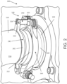
FIG. 2 illustrates a tubing system, in accordance with various embodiments; -
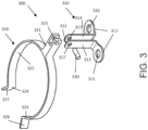
FIG. 3 illustrates an exploded view of a retaining assembly, in accordance with various embodiments; -
FIG. 4 illustrates an exploded view of a clamp assembly, in accordance with various embodiments; and -
FIG. 5 illustrates a clamp assembly in use, in accordance with various embodiments. - The detailed description of embodiments herein makes reference to the accompanying drawings, which show embodiments by way of illustration. While these embodiments are described in sufficient detail to enable those skilled in the art to practice the inventions, it should be understood that other embodiments may be realized and that logical and mechanical changes may be made without departing from the scope of the inventions. Thus, the detailed description herein is presented for purposes of illustration only and not of limitation. For example, the steps recited in any of the method or process descriptions may be executed in any order and are not necessarily limited to the order presented. Furthermore, any reference to singular includes plural embodiments, and any reference to more than one component or step may include a singular embodiment or step. Also, any reference to attached, fixed, connected or the like may include permanent, removable, temporary, partial, full and/or any other possible attachment option. Additionally, any reference to without contact (or similar phrases) may also include reduced contact or minimal contact.
- Disclosed herein is a retaining assembly configured retain a clamp assembly to a fixed tubing structure during maintenance operations of a gas turbine engine. In accordance with various embodiments, the retaining assembly may include a retention component configured to retain the clamp assembly to a tube assembly. The retaining assembly includes a bracket assembly configured to couple the retention component to a clamp. The clamp assembly includes the retaining assembly and is configured to connect a first tube to a second tube. Accordingly, a clamp assembly having a retaining assembly, as disclosed herein, can reduce or eliminate the possibility of misplacing or dropping a clamp assembly during maintenance operations of a gas turbine engine.
- Referring now to the drawings,
FIG. 1 schematically illustrates agas turbine engine 20. Thegas turbine engine 20 is disclosed herein as a two-spool turbofan that generally incorporates afan section 22, acompressor section 24, acombustor section 26 and aturbine section 28. Thefan section 22 drives air along a bypass flow path B in a bypass duct defined within anacelle 15, while thecompressor section 24 drives air along a core or primary flow path C for compression and communication into thecombustor section 26 and then expansion through theturbine section 28. Although depicted as a two-spool turbofan gas turbine engine in the disclosed non-limiting embodiment, it should be understood that the concepts described herein are not limited to use with two-spool turbofans as the teachings may be applied to other types of turbine engines. - The
gas turbine engine 20 generally includes alow speed spool 30 and ahigh speed spool 32 mounted for rotation about an engine central longitudinal axis A relative to an enginestatic structure 36 viaseveral bearing systems 38. It should be understood that various bearing systems at various locations may alternatively or additionally be provided and the location of theseveral bearing systems 38 may be varied as appropriate to the application. Thelow speed spool 30 generally includes aninner shaft 40 that interconnects afan 42, alow pressure compressor 44 and alow pressure turbine 46. Theinner shaft 40 is connected to thefan 42 through a speed change mechanism, which in thisgas turbine engine 20 is illustrated as a fan drive gear system 48 configured to drive thefan 42 at a lower speed than thelow speed spool 30. Thehigh speed spool 32 includes anouter shaft 50 that interconnects ahigh pressure compressor 52 and ahigh pressure turbine 54. Acombustor 56 is arranged in thegas turbine engine 20 between thehigh pressure compressor 52 and thehigh pressure turbine 54. Amid-turbine frame 57 of the enginestatic structure 36 is arranged generally between thehigh pressure turbine 54 and thelow pressure turbine 46 and may includeairfoils 59 in the core flow path C for guiding the flow into thelow pressure turbine 46. Themid-turbine frame 57 further supports theseveral bearing systems 38 in theturbine section 28. Theinner shaft 40 and theouter shaft 50 are concentric and rotate via theseveral bearing systems 38 about the engine central longitudinal axis A, which is collinear with longitudinal axes of theinner shaft 40 and theouter shaft 50. - The air in the core flow path C is compressed by the
low pressure compressor 44 and then thehigh pressure compressor 52, mixed and burned with fuel in thecombustor 56, and then expanded over thehigh pressure turbine 54 andlow pressure turbine 46. Thelow pressure turbine 46 and thehigh pressure turbine 54 rotationally drive the respectivelow speed spool 30 and thehigh speed spool 32 in response to the expansion. It will be appreciated that each of the positions of thefan section 22, thecompressor section 24, thecombustor section 26, theturbine section 28, and the fan drive gear system 48 may be varied. For example, the fan drive gear system 48 may be located aft of thecombustor section 26 or even aft of theturbine section 28, and thefan section 22 may be positioned forward or aft of the location of the fan drive gear system 48. - With reference to
FIG. 2 , a tubing system in a gas turbine engine is shown, in accordance with various embodiments.Tubing system 200 may provide various fluids (e.g., air, oil, fuel, hydraulic, etc) to components in various compartments in gas turbine engine 100 inFIG. 1 . For example, with momentary combined reference toFIGs. 1 and2 ,tubing system 200 may provide bleed air from the compressor section (44, 52) to the nacelle. - In various embodiments, a
tubing system 200 may include afirst tube 210 having afirst tube end 212 and asecond tube 220 having asecond tube end 222. Thefirst tube end 212 may be coupled to thesecond tube end 222 by aclamp assembly 230. Theclamp assembly 230 may include asleeve 240 having asemi-annular portion 242 and aclevis 244. Thesemi-annular portion 242 of thesleeve 240 may be coupled to thefirst tube 210 on anouter surface 214 of thefirst tube 210. The connection of thesleeve 240 to thefirst tube 210 may be fixed or removable. - In various embodiments, the
sleeve 240 is fixedly connected to thefirst tube 210 by brazing, or any other method known in the art. In various embodiments, thesleeve 240 is connected to thefirst tube 210 by a retaining component that retains the clamp assembly in place but may be removable from thefirst tube 210. Theclamp assembly 230 further includes abracket assembly 250 having afirst bracket end 252 and asecond bracket end 254. The bracket assembly may be a single machined piece or multiple sheet metal brackets. Thesecond bracket end 254 may be coupled to theclevis 244 via a fastener, a pin, or any other connection method known in the art. Theclamping band 260 may be configured to join thefirst tube end 212 of thefirst tube 210 to thesecond tube end 222 of thesecond tube 220. - In various embodiments,
first tube 210 andsecond tube 220 may comprise a high temperature metal (e.g., an austenitic nickel-chromium-based alloy such as that available under the trade name INCONEL), a high temperature composite, and/or the like. In various embodiments,first tube 210 andsecond tube 220 may comprise a high temperature stainless steel (e.g., type 330 stainless steel). Similarly, thesleeve 240 may comprise a high temperature metal that is similar, or the same asfirst tube 210. In various embodiments, a similarfirst tube 210 material andsleeve 240 material may ensure effective brazing in a fixedly attached configuration. - With reference now to
FIG. 3 , an exploded view of a retainingassembly 300, in accordance with various embodiments is illustrated. The retainingassembly 300 comprises abracket assembly 310 and aretention component 320. Thebracket assembly 310 comprises afirst bracket end 311 and asecond bracket end 312. Thefirst bracket end 311 of the bracket assembly may comprise afirst mounting point 315 and asecond mounting point 316. The mounting points (315, 316) may be configured to mount to aclamping band 260. Although described with a clamping band assembly, the bracket assembly could be configured to mount to any component that may become loose, lost, or misplaced during maintenance operations on a gas turbine engine. Thebracket assembly 310 further comprises a first L-bracket 313 and a second L-bracket 314. Each bracket (313,314) may be a single bend sheet metal bracket of standard thickness, such as 0.00625" -0.25", more preferably 0.025" - 0.125", even more preferably 0.05" - 0.09375". In various embodiments,bracket assembly 310 may be a single, monolithic machined component. Thesecond bracket end 312 of thebracket assembly 310 may comprise afirst pin aperture 317 and asecond pin aperture 317. The pin apertures (317, 317) may be aligned with abracket end 321 of theretention component 320 and couple thebracket assembly 310 to theretention component 320. - In various embodiments, the
retention component 320 may comprise abracket end 321, asemi-annular portion 322, afirst retention end 323 and asecond retention end 324. The semi-annular portion may be greater than 180 degrees from thefirst retention end 323 to thesecond retention end 324 and correspond to an outer diameter of a tube. Thefirst retention end 323 may comprisefirst lip portion 326 and thesecond retention end 324 may comprise asecond lip portion 327, the lip portions (326, 327) being configured to allow easy installation on a tube, as well as easy removal from a tube. Thesemi-annular portion 322 may be flexible and configured to expand when being installed and apply a retention force once installed on a tube. This retention force will allow theretention component 320 to hold thebracket assembly 310 and a clamping band during in line maintenance of a gas turbine engine. - In various embodiments,
bracket assembly 310 andretention component 320 may comprise a high temperature metal (e.g., an austenitic nickel-chromium-based alloy such as that available under the trade name INCONEL), a high temperature composite, and/or the like. In various embodiments,bracket assembly 310 andretention component 320 may comprise a high temperature stainless steel (e.g., type 330 stainless steel).Bracket assembly 310 andretention component 320 may have similar, or dissimilar materials. - In various embodiments, the
bracket end 321 of theretention component 320 may comprise aclevis 325. Theclevis 325 may align with the pin apertures (317, 317) of thebracket assembly 310 and apin 330 may fasten thebracket assembly 310 to theretention component 320. Although apin 330 is depicted, the connection could be made by any fastening means known in the art, such as a bolt and nut, a rivet, a screw, etc. Thepin 330 may form a fulcrum, about which the bracket assembly may rotate with respect to theretention component 320 when the retention component is fixed. The bracket assembly being able to rotate about the fulcrum may allow the retention component to remain fixed on a tube during maintenance operations and allow an otherwise loose clamping band mounted to the bracket to remain attached to a gas turbine engine during maintenance to prevent losing or misplacing the component. - With reference now to
FIG. 4 , an exploded view of a clamp assembly, in accordance with various embodiments is illustrated. Aclamp assembly 400 comprises aclamping band 260 and a retainingassembly 300, as shown inFIG. 3 . Theclamping band 260 further comprises afirst clamping arm 262 and asecond clamping arm 264, and may also comprise ahinge connector 266, abolt 270 coupled to thesecond clamping arm 264, and anut 272 coupled opposite the connection between thesecond clamping arm 264 and thebolt 270. When in an assembled position, thefirst clamping arm 262 and thesecond clamping arm 264 compress a flange from a first tube with a flange from a second tube and connecting the tubes together. Although anut 272 and bolt 270 connection is depicted, and clamping band connection known in the art could be utilized, such as a quick release latch, a T-bolt latch, etc. Both thefirst clamping arm 262 and thesecond clamping arm 264 may have a clevis (263, 265). Each clevis (263, 265) may correspond to respective apertures (267, 268) onhinge connector 266 and the mounting points (315, 316) of thebracket assembly 310. Thebracket assembly 310 may be mounted to theclamping band 260 by aligning the mounting points (315, 316) with the clevises (263, 265) and the apertures (267, 268) in thehinge connector 266, and placing pins (471,472) through the stacks. - With reference now to
FIG. 5 , aclamp assembly 400 in use during maintenance on a gas turbine engine is depicted. This may fix theclamping band 260 to the retainingassembly 300, so an otherwise loose external component (the clamping band 260) may be retained on a fixed component (a tube 510) and rotated about thefulcrum 331 of the retainingassembly 300 to move theclamping band 260 out of the way from maintenance, and to fix theclamping band 260 in place to ensure it is not misplaced or lost. - Although described herein with respect to tubing systems corresponding to bleed air systems, the clamping assembly and retaining assembly may be used with any other suitable connection such as fuel tube connections, lubrication return tube connections, hydraulic tube connections, and the like.
- Benefits, other advantages, and solutions to problems have been described herein with regard to specific embodiments. The scope of the inventions is accordingly to be limited by nothing other than the appended claims, in which reference to an element in the singular is not intended to mean "one and only one" unless explicitly so stated, but rather "one or more." Moreover, where a phrase similar to "at least one of A, B, or C" is used in the claims, it is intended that the phrase be interpreted to mean that A alone may be present in an embodiment, B alone may be present in an embodiment, C alone may be present in an embodiment, or that any combination of the elements A, B and C may be present in a single embodiment; for example, A and B, A and C, B and C, or A and B and C. Different cross-hatching is used throughout the figures to denote different parts but not necessarily to denote the same or different materials.
- Systems, methods and apparatus are provided herein. In the detailed description herein, references to "one embodiment", "an embodiment", "various embodiments", etc., indicate that the embodiment described may include a particular feature, structure, or characteristic, but every embodiment may not necessarily include the particular feature, structure, or characteristic. After reading the description, it will be apparent to one skilled in the relevant art(s) how to implement the disclosure in alternative embodiments. As used herein, the terms "comprises," "comprising," or any other variation thereof, are intended to cover a non-exclusive inclusion, such that a process, method, article, or apparatus that comprises a list of elements does not include only those elements but may include other elements not expressly listed or inherent to such process, method, article, or apparatus.
Claims (7)
- A clamp assembly (230; 400), comprising:a clamping band (260); anda retaining assembly (300) comprising:a bracket assembly (250; 310) having a first bracket end (252) and a second bracket end (254), the first bracket end (252) being configured to mount to a clamping band (260), wherein the bracket assembly (250; 310) comprises a first L-bracket (313) having a first hinge aperture (317) and a second L-bracket (314) having a second hinge aperture (317); anda retention component (320) having a clevis (244; 325) coupled to the second bracket end (254), wherein the retention component (320) comprises a spring loaded clip, wherein a first clamping arm (262) of the clamping band (260) is coupled to the first L-bracket (313) and configured to pivot about a first hinge (471) and a second clamping arm (264) of the clamping band (260) is coupled to the second L-bracket (314) and configured to pivot about a second hinge (472), andwherein the clamping band (260) is configured to join a first tube end of a first tube to a second tube end of a second tube.
- The clamp assembly (230; 400) of claim 1, wherein the second bracket end (254) and the clevis (244, 325) define a fulcrum (331), the bracket assembly (250; 310) being able to rotate about the fulcrum (331).
- The clamp assembly (230; 400) of claim 1 or 2, wherein the retention component (320) comprises a spring-loaded clamp.
- The clamp assembly (230; 400) of claim 1, 2 or 3, wherein the first hinge aperture (317) and the second hinge aperture (317) are coupled to the clevis (325) via a pin (330).
- The clamp assembly (230; 400) of claim 1, wherein the clevis (325) and the second bracket end (254) define a fulcrum (331), the clevis (325) being able to rotate via the bracket assembly (250; 310) about the fulcrum (331).
- The clamp assembly (230; 400) of any of claims 1 to 5, wherein the retention component (320) comprises at least one of a worm gear or a fastener configured to either loosen or tighten the retention component (320).
- The clamp assembly (230; 400) of any of claims 1 to 6, wherein the retention component (320) comprises a chain or a band/strap.
Applications Claiming Priority (1)
| Application Number | Priority Date | Filing Date | Title |
|---|---|---|---|
| US16/257,917 US11384877B2 (en) | 2019-01-25 | 2019-01-25 | Retaining assembly for a gas turbine engine |
Publications (3)
| Publication Number | Publication Date |
|---|---|
| EP3748211A2 EP3748211A2 (en) | 2020-12-09 |
| EP3748211A3 EP3748211A3 (en) | 2021-04-28 |
| EP3748211B1 true EP3748211B1 (en) | 2024-03-27 |
Family
ID=69187713
Family Applications (1)
| Application Number | Title | Priority Date | Filing Date |
|---|---|---|---|
| EP20153210.8A Active EP3748211B1 (en) | 2019-01-25 | 2020-01-22 | Retaining assembly for a gas turbine engine |
Country Status (2)
| Country | Link |
|---|---|
| US (1) | US11384877B2 (en) |
| EP (1) | EP3748211B1 (en) |
Families Citing this family (4)
| Publication number | Priority date | Publication date | Assignee | Title |
|---|---|---|---|---|
| DE102016103986B3 (en) * | 2016-03-04 | 2017-08-24 | Norma Germany Gmbh | Prepositioner for a profile clamp and connection arrangement with such a pre-positioner |
| DE102022105973A1 (en) * | 2022-03-15 | 2023-09-21 | Norma Germany Gmbh | profile clamp |
| CN115027683B (en) * | 2022-06-23 | 2025-06-27 | 中国航发贵阳发动机设计研究所 | Aircraft engine accessory installation method and inspection tool |
| WO2024059561A1 (en) * | 2022-09-12 | 2024-03-21 | Forum Us, Inc. | Pump manifold systems |
Family Cites Families (26)
| Publication number | Priority date | Publication date | Assignee | Title |
|---|---|---|---|---|
| US1910706A (en) * | 1932-06-10 | 1933-05-23 | Hercules Coupling Company | Pipe or hose coupling |
| US3489434A (en) | 1966-09-26 | 1970-01-13 | Frank Haley | Pipe coupling |
| FR2404793A1 (en) * | 1977-09-30 | 1979-04-27 | Usinor | ASSEMBLY DEVICE, ESPECIALLY BETWEEN TWO Sections OF A HAUT-FOURNEAU WIND DESCENT |
| US4432524A (en) * | 1981-07-29 | 1984-02-21 | General Motors Corporation | Three point seat adjuster |
| NO884626L (en) * | 1987-10-19 | 1989-04-20 | Techlok Ltd | CLAMP. |
| US5052608A (en) | 1989-11-28 | 1991-10-01 | Mcclure Gary W | Pipe fitting tool |
| US5226231A (en) | 1992-08-12 | 1993-07-13 | Marcel De Leebeeck | Pipe joining tool |
| FR2697893B1 (en) * | 1992-11-06 | 1995-01-27 | Goavec Sa | Collar for the removable connection of two pipes. |
| DE29519866U1 (en) | 1995-12-14 | 1996-02-01 | Vulkatec Riebensahm GmbH, 56630 Kretz | Holding device for flexible hoses |
| GB2311480B (en) | 1996-03-26 | 1998-02-18 | Chern Yeong Ren | Clamping assembly |
| CN101115943A (en) * | 2005-02-11 | 2008-01-30 | 爱瑞柯国际公司 | U-shaped hanger and method for supporting pipelines |
| ATE467792T1 (en) * | 2008-01-31 | 2010-05-15 | Mat Mischanlagentechnik Gmbh | PUMPING DEVICE |
| US8658931B2 (en) | 2010-04-15 | 2014-02-25 | Impact Power, Inc. | Three phase vacuum interrupter switch for high voltage distribution systems |
| DE202010012940U1 (en) * | 2010-05-12 | 2011-01-27 | Georg Springmann Industrie- Und Bergbautechnik Gmbh | Pipe and hose coupling |
| DE102012213640A1 (en) | 2012-08-02 | 2014-02-06 | Martin Polt | Pipe connecting device for connecting two drainage pipes, has two clamping devices formed for holding pipes that are aligned with each other on holding, where clamping devices are connected to each other through connection unit |
| US9261022B2 (en) * | 2012-12-07 | 2016-02-16 | General Electric Company | System for controlling a cooling flow from a compressor section of a gas turbine |
| DE202013001224U1 (en) | 2013-02-07 | 2013-02-15 | Norma Germany Gmbh | Clamp with pre-positioner |
| US20150137505A1 (en) * | 2013-11-21 | 2015-05-21 | Lokar, Inc. | Header Tethering System |
| US9808893B2 (en) | 2013-12-19 | 2017-11-07 | Walhonde Tools Inc. | Apparatus for aligning sections of pipe |
| EP2955393A1 (en) * | 2014-06-13 | 2015-12-16 | Siemens Aktiengesellschaft | Connection clamp with metal wire mat as damping element |
| FR3025581B1 (en) * | 2014-09-04 | 2017-03-24 | Caillau Ets | SYSTEM FOR CONNECTING TWO TUBES |
| US9874147B2 (en) * | 2015-01-20 | 2018-01-23 | United Technologies Corporation | V-band clamp with integral mount plate |
| FR3033018B1 (en) * | 2015-02-24 | 2017-10-13 | Airbus Operations Sas | TUBULAR ELEMENT SUPPORT PART, IN PARTICULAR FOR AN AIRCRAFT. |
| SE539329C2 (en) * | 2015-08-25 | 2017-07-04 | Wayne Fueling Systems Sweden Ab | Clamp device for a fuel dispenser |
| KR20160124040A (en) * | 2016-07-25 | 2016-10-26 | 권혜경 | Keeping Warm and Insulation Structure for Skirt Part of vinylhouse |
| US9709198B1 (en) | 2016-11-29 | 2017-07-18 | General Electric Company | Clamped connector systems for use with piping assemblies |
-
2019
- 2019-01-25 US US16/257,917 patent/US11384877B2/en active Active
-
2020
- 2020-01-22 EP EP20153210.8A patent/EP3748211B1/en active Active
Also Published As
| Publication number | Publication date |
|---|---|
| EP3748211A3 (en) | 2021-04-28 |
| US11384877B2 (en) | 2022-07-12 |
| US20200240557A1 (en) | 2020-07-30 |
| EP3748211A2 (en) | 2020-12-09 |
Similar Documents
| Publication | Publication Date | Title |
|---|---|---|
| EP3748211B1 (en) | Retaining assembly for a gas turbine engine | |
| EP3225779B1 (en) | Removal tool | |
| US8454056B2 (en) | Double strap coupling apparatus | |
| US5407237A (en) | Flexible coupling | |
| JP6587999B2 (en) | Gas turbine engine disassembly / assembly support device | |
| EP3018305A1 (en) | Exhaust nozzle center body attachment | |
| US20110056055A1 (en) | Member for locking ring sectors on a turbine engine casing, including radial passages for gripping same | |
| US9382875B2 (en) | Spherical button washer for exhaust duct liner hanger | |
| EP3992434B1 (en) | Service tube assembly for a gas turbine engine | |
| EP3833896B1 (en) | Clamp assembly with retainer | |
| US12173747B2 (en) | Turnbuckle linkage | |
| EP3597869B1 (en) | Sealing configuration for a transfer tube assembly to reduce air leakage | |
| US9494109B2 (en) | Pivoting ball stop for exhaust duct liner hanger | |
| EP3708811A1 (en) | Engine exhaust skin connection system | |
| EP2743458B1 (en) | Apparatus and method for installing and removing a turbine transition piece | |
| US20180272514A1 (en) | Spring loaded pilot punch assembly | |
| EP3045741B1 (en) | Captive component on a fastener | |
| EP3193038B1 (en) | Heat exchanger for cooled cooling air with adjustable damper | |
| US11143341B2 (en) | Balking tab to control duct coupling clocking | |
| US12385581B2 (en) | Fastening assembly | |
| EP3418618B1 (en) | Middle threaded fitting | |
| EP3392473B1 (en) | Towershaft support | |
| EP1882097B1 (en) | Fuel distributor and mounting system therefor and method of mounting a fuel distributor | |
| EP3819479B1 (en) | Mechanical attachment scheme for isogrid ducts | |
| JP7214736B2 (en) | hose connection system |
Legal Events
| Date | Code | Title | Description |
|---|---|---|---|
| PUAI | Public reference made under article 153(3) epc to a published international application that has entered the european phase |
Free format text: ORIGINAL CODE: 0009012 |
|
| STAA | Information on the status of an ep patent application or granted ep patent |
Free format text: STATUS: THE APPLICATION HAS BEEN PUBLISHED |
|
| AK | Designated contracting states |
Kind code of ref document: A2 Designated state(s): AL AT BE BG CH CY CZ DE DK EE ES FI FR GB GR HR HU IE IS IT LI LT LU LV MC MK MT NL NO PL PT RO RS SE SI SK SM TR |
|
| AX | Request for extension of the european patent |
Extension state: BA ME |
|
| RAP1 | Party data changed (applicant data changed or rights of an application transferred) |
Owner name: RAYTHEON TECHNOLOGIES CORPORATION |
|
| PUAL | Search report despatched |
Free format text: ORIGINAL CODE: 0009013 |
|
| AK | Designated contracting states |
Kind code of ref document: A3 Designated state(s): AL AT BE BG CH CY CZ DE DK EE ES FI FR GB GR HR HU IE IS IT LI LT LU LV MC MK MT NL NO PL PT RO RS SE SI SK SM TR |
|
| AX | Request for extension of the european patent |
Extension state: BA ME |
|
| RIC1 | Information provided on ipc code assigned before grant |
Ipc: F16L 23/08 20060101AFI20210325BHEP Ipc: F16L 1/06 20060101ALI20210325BHEP |
|
| STAA | Information on the status of an ep patent application or granted ep patent |
Free format text: STATUS: REQUEST FOR EXAMINATION WAS MADE |
|
| 17P | Request for examination filed |
Effective date: 20211026 |
|
| RBV | Designated contracting states (corrected) |
Designated state(s): AL AT BE BG CH CY CZ DE DK EE ES FI FR GB GR HR HU IE IS IT LI LT LU LV MC MK MT NL NO PL PT RO RS SE SI SK SM TR |
|
| GRAP | Despatch of communication of intention to grant a patent |
Free format text: ORIGINAL CODE: EPIDOSNIGR1 |
|
| STAA | Information on the status of an ep patent application or granted ep patent |
Free format text: STATUS: GRANT OF PATENT IS INTENDED |
|
| INTG | Intention to grant announced |
Effective date: 20230413 |
|
| GRAJ | Information related to disapproval of communication of intention to grant by the applicant or resumption of examination proceedings by the epo deleted |
Free format text: ORIGINAL CODE: EPIDOSDIGR1 |
|
| STAA | Information on the status of an ep patent application or granted ep patent |
Free format text: STATUS: REQUEST FOR EXAMINATION WAS MADE |
|
| INTC | Intention to grant announced (deleted) | ||
| GRAP | Despatch of communication of intention to grant a patent |
Free format text: ORIGINAL CODE: EPIDOSNIGR1 |
|
| STAA | Information on the status of an ep patent application or granted ep patent |
Free format text: STATUS: GRANT OF PATENT IS INTENDED |
|
| RAP3 | Party data changed (applicant data changed or rights of an application transferred) |
Owner name: RTX CORPORATION |
|
| INTG | Intention to grant announced |
Effective date: 20231011 |
|
| GRAS | Grant fee paid |
Free format text: ORIGINAL CODE: EPIDOSNIGR3 |
|
| GRAA | (expected) grant |
Free format text: ORIGINAL CODE: 0009210 |
|
| STAA | Information on the status of an ep patent application or granted ep patent |
Free format text: STATUS: THE PATENT HAS BEEN GRANTED |
|
| AK | Designated contracting states |
Kind code of ref document: B1 Designated state(s): AL AT BE BG CH CY CZ DE DK EE ES FI FR GB GR HR HU IE IS IT LI LT LU LV MC MK MT NL NO PL PT RO RS SE SI SK SM TR |
|
| REG | Reference to a national code |
Ref country code: GB Ref legal event code: FG4D |
|
| REG | Reference to a national code |
Ref country code: CH Ref legal event code: EP |
|
| REG | Reference to a national code |
Ref country code: DE Ref legal event code: R096 Ref document number: 602020027742 Country of ref document: DE |
|
| REG | Reference to a national code |
Ref country code: IE Ref legal event code: FG4D |
|
| PG25 | Lapsed in a contracting state [announced via postgrant information from national office to epo] |
Ref country code: LT Free format text: LAPSE BECAUSE OF FAILURE TO SUBMIT A TRANSLATION OF THE DESCRIPTION OR TO PAY THE FEE WITHIN THE PRESCRIBED TIME-LIMIT Effective date: 20240327 |
|
| REG | Reference to a national code |
Ref country code: LT Ref legal event code: MG9D |
|
| PG25 | Lapsed in a contracting state [announced via postgrant information from national office to epo] |
Ref country code: GR Free format text: LAPSE BECAUSE OF FAILURE TO SUBMIT A TRANSLATION OF THE DESCRIPTION OR TO PAY THE FEE WITHIN THE PRESCRIBED TIME-LIMIT Effective date: 20240628 |
|
| PG25 | Lapsed in a contracting state [announced via postgrant information from national office to epo] |
Ref country code: RS Free format text: LAPSE BECAUSE OF FAILURE TO SUBMIT A TRANSLATION OF THE DESCRIPTION OR TO PAY THE FEE WITHIN THE PRESCRIBED TIME-LIMIT Effective date: 20240627 Ref country code: HR Free format text: LAPSE BECAUSE OF FAILURE TO SUBMIT A TRANSLATION OF THE DESCRIPTION OR TO PAY THE FEE WITHIN THE PRESCRIBED TIME-LIMIT Effective date: 20240327 |
|
| PG25 | Lapsed in a contracting state [announced via postgrant information from national office to epo] |
Ref country code: RS Free format text: LAPSE BECAUSE OF FAILURE TO SUBMIT A TRANSLATION OF THE DESCRIPTION OR TO PAY THE FEE WITHIN THE PRESCRIBED TIME-LIMIT Effective date: 20240627 Ref country code: NO Free format text: LAPSE BECAUSE OF FAILURE TO SUBMIT A TRANSLATION OF THE DESCRIPTION OR TO PAY THE FEE WITHIN THE PRESCRIBED TIME-LIMIT Effective date: 20240627 Ref country code: LT Free format text: LAPSE BECAUSE OF FAILURE TO SUBMIT A TRANSLATION OF THE DESCRIPTION OR TO PAY THE FEE WITHIN THE PRESCRIBED TIME-LIMIT Effective date: 20240327 Ref country code: HR Free format text: LAPSE BECAUSE OF FAILURE TO SUBMIT A TRANSLATION OF THE DESCRIPTION OR TO PAY THE FEE WITHIN THE PRESCRIBED TIME-LIMIT Effective date: 20240327 Ref country code: GR Free format text: LAPSE BECAUSE OF FAILURE TO SUBMIT A TRANSLATION OF THE DESCRIPTION OR TO PAY THE FEE WITHIN THE PRESCRIBED TIME-LIMIT Effective date: 20240628 Ref country code: FI Free format text: LAPSE BECAUSE OF FAILURE TO SUBMIT A TRANSLATION OF THE DESCRIPTION OR TO PAY THE FEE WITHIN THE PRESCRIBED TIME-LIMIT Effective date: 20240327 Ref country code: BG Free format text: LAPSE BECAUSE OF FAILURE TO SUBMIT A TRANSLATION OF THE DESCRIPTION OR TO PAY THE FEE WITHIN THE PRESCRIBED TIME-LIMIT Effective date: 20240327 |
|
| REG | Reference to a national code |
Ref country code: NL Ref legal event code: MP Effective date: 20240327 |
|
| PG25 | Lapsed in a contracting state [announced via postgrant information from national office to epo] |
Ref country code: SE Free format text: LAPSE BECAUSE OF FAILURE TO SUBMIT A TRANSLATION OF THE DESCRIPTION OR TO PAY THE FEE WITHIN THE PRESCRIBED TIME-LIMIT Effective date: 20240327 Ref country code: LV Free format text: LAPSE BECAUSE OF FAILURE TO SUBMIT A TRANSLATION OF THE DESCRIPTION OR TO PAY THE FEE WITHIN THE PRESCRIBED TIME-LIMIT Effective date: 20240327 |
|
| PG25 | Lapsed in a contracting state [announced via postgrant information from national office to epo] |
Ref country code: NL Free format text: LAPSE BECAUSE OF FAILURE TO SUBMIT A TRANSLATION OF THE DESCRIPTION OR TO PAY THE FEE WITHIN THE PRESCRIBED TIME-LIMIT Effective date: 20240327 |
|
| REG | Reference to a national code |
Ref country code: AT Ref legal event code: MK05 Ref document number: 1670219 Country of ref document: AT Kind code of ref document: T Effective date: 20240327 |
|
| PG25 | Lapsed in a contracting state [announced via postgrant information from national office to epo] |
Ref country code: NL Free format text: LAPSE BECAUSE OF FAILURE TO SUBMIT A TRANSLATION OF THE DESCRIPTION OR TO PAY THE FEE WITHIN THE PRESCRIBED TIME-LIMIT Effective date: 20240327 |
|
| PG25 | Lapsed in a contracting state [announced via postgrant information from national office to epo] |
Ref country code: IS Free format text: LAPSE BECAUSE OF FAILURE TO SUBMIT A TRANSLATION OF THE DESCRIPTION OR TO PAY THE FEE WITHIN THE PRESCRIBED TIME-LIMIT Effective date: 20240727 |
|
| PG25 | Lapsed in a contracting state [announced via postgrant information from national office to epo] |
Ref country code: PT Free format text: LAPSE BECAUSE OF FAILURE TO SUBMIT A TRANSLATION OF THE DESCRIPTION OR TO PAY THE FEE WITHIN THE PRESCRIBED TIME-LIMIT Effective date: 20240729 Ref country code: SM Free format text: LAPSE BECAUSE OF FAILURE TO SUBMIT A TRANSLATION OF THE DESCRIPTION OR TO PAY THE FEE WITHIN THE PRESCRIBED TIME-LIMIT Effective date: 20240327 |
|
| PG25 | Lapsed in a contracting state [announced via postgrant information from national office to epo] |
Ref country code: ES Free format text: LAPSE BECAUSE OF FAILURE TO SUBMIT A TRANSLATION OF THE DESCRIPTION OR TO PAY THE FEE WITHIN THE PRESCRIBED TIME-LIMIT Effective date: 20240327 |
|
| PG25 | Lapsed in a contracting state [announced via postgrant information from national office to epo] |
Ref country code: CZ Free format text: LAPSE BECAUSE OF FAILURE TO SUBMIT A TRANSLATION OF THE DESCRIPTION OR TO PAY THE FEE WITHIN THE PRESCRIBED TIME-LIMIT Effective date: 20240327 Ref country code: EE Free format text: LAPSE BECAUSE OF FAILURE TO SUBMIT A TRANSLATION OF THE DESCRIPTION OR TO PAY THE FEE WITHIN THE PRESCRIBED TIME-LIMIT Effective date: 20240327 |
|
| PG25 | Lapsed in a contracting state [announced via postgrant information from national office to epo] |
Ref country code: AT Free format text: LAPSE BECAUSE OF FAILURE TO SUBMIT A TRANSLATION OF THE DESCRIPTION OR TO PAY THE FEE WITHIN THE PRESCRIBED TIME-LIMIT Effective date: 20240327 |
|
| PG25 | Lapsed in a contracting state [announced via postgrant information from national office to epo] |
Ref country code: PL Free format text: LAPSE BECAUSE OF FAILURE TO SUBMIT A TRANSLATION OF THE DESCRIPTION OR TO PAY THE FEE WITHIN THE PRESCRIBED TIME-LIMIT Effective date: 20240327 |
|
| PG25 | Lapsed in a contracting state [announced via postgrant information from national office to epo] |
Ref country code: SK Free format text: LAPSE BECAUSE OF FAILURE TO SUBMIT A TRANSLATION OF THE DESCRIPTION OR TO PAY THE FEE WITHIN THE PRESCRIBED TIME-LIMIT Effective date: 20240327 |
|
| PG25 | Lapsed in a contracting state [announced via postgrant information from national office to epo] |
Ref country code: SM Free format text: LAPSE BECAUSE OF FAILURE TO SUBMIT A TRANSLATION OF THE DESCRIPTION OR TO PAY THE FEE WITHIN THE PRESCRIBED TIME-LIMIT Effective date: 20240327 Ref country code: SK Free format text: LAPSE BECAUSE OF FAILURE TO SUBMIT A TRANSLATION OF THE DESCRIPTION OR TO PAY THE FEE WITHIN THE PRESCRIBED TIME-LIMIT Effective date: 20240327 Ref country code: RO Free format text: LAPSE BECAUSE OF FAILURE TO SUBMIT A TRANSLATION OF THE DESCRIPTION OR TO PAY THE FEE WITHIN THE PRESCRIBED TIME-LIMIT Effective date: 20240327 Ref country code: PT Free format text: LAPSE BECAUSE OF FAILURE TO SUBMIT A TRANSLATION OF THE DESCRIPTION OR TO PAY THE FEE WITHIN THE PRESCRIBED TIME-LIMIT Effective date: 20240729 Ref country code: PL Free format text: LAPSE BECAUSE OF FAILURE TO SUBMIT A TRANSLATION OF THE DESCRIPTION OR TO PAY THE FEE WITHIN THE PRESCRIBED TIME-LIMIT Effective date: 20240327 Ref country code: IS Free format text: LAPSE BECAUSE OF FAILURE TO SUBMIT A TRANSLATION OF THE DESCRIPTION OR TO PAY THE FEE WITHIN THE PRESCRIBED TIME-LIMIT Effective date: 20240727 Ref country code: ES Free format text: LAPSE BECAUSE OF FAILURE TO SUBMIT A TRANSLATION OF THE DESCRIPTION OR TO PAY THE FEE WITHIN THE PRESCRIBED TIME-LIMIT Effective date: 20240327 Ref country code: EE Free format text: LAPSE BECAUSE OF FAILURE TO SUBMIT A TRANSLATION OF THE DESCRIPTION OR TO PAY THE FEE WITHIN THE PRESCRIBED TIME-LIMIT Effective date: 20240327 Ref country code: CZ Free format text: LAPSE BECAUSE OF FAILURE TO SUBMIT A TRANSLATION OF THE DESCRIPTION OR TO PAY THE FEE WITHIN THE PRESCRIBED TIME-LIMIT Effective date: 20240327 Ref country code: AT Free format text: LAPSE BECAUSE OF FAILURE TO SUBMIT A TRANSLATION OF THE DESCRIPTION OR TO PAY THE FEE WITHIN THE PRESCRIBED TIME-LIMIT Effective date: 20240327 |
|
| PG25 | Lapsed in a contracting state [announced via postgrant information from national office to epo] |
Ref country code: IT Free format text: LAPSE BECAUSE OF FAILURE TO SUBMIT A TRANSLATION OF THE DESCRIPTION OR TO PAY THE FEE WITHIN THE PRESCRIBED TIME-LIMIT Effective date: 20240327 |
|
| PG25 | Lapsed in a contracting state [announced via postgrant information from national office to epo] |
Ref country code: IT Free format text: LAPSE BECAUSE OF FAILURE TO SUBMIT A TRANSLATION OF THE DESCRIPTION OR TO PAY THE FEE WITHIN THE PRESCRIBED TIME-LIMIT Effective date: 20240327 |
|
| REG | Reference to a national code |
Ref country code: DE Ref legal event code: R097 Ref document number: 602020027742 Country of ref document: DE |
|
| PG25 | Lapsed in a contracting state [announced via postgrant information from national office to epo] |
Ref country code: DK Free format text: LAPSE BECAUSE OF FAILURE TO SUBMIT A TRANSLATION OF THE DESCRIPTION OR TO PAY THE FEE WITHIN THE PRESCRIBED TIME-LIMIT Effective date: 20240327 |
|
| PG25 | Lapsed in a contracting state [announced via postgrant information from national office to epo] |
Ref country code: DK Free format text: LAPSE BECAUSE OF FAILURE TO SUBMIT A TRANSLATION OF THE DESCRIPTION OR TO PAY THE FEE WITHIN THE PRESCRIBED TIME-LIMIT Effective date: 20240327 |
|
| PLBE | No opposition filed within time limit |
Free format text: ORIGINAL CODE: 0009261 |
|
| STAA | Information on the status of an ep patent application or granted ep patent |
Free format text: STATUS: NO OPPOSITION FILED WITHIN TIME LIMIT |
|
| 26N | No opposition filed |
Effective date: 20250103 |
|
| PG25 | Lapsed in a contracting state [announced via postgrant information from national office to epo] |
Ref country code: SI Free format text: LAPSE BECAUSE OF FAILURE TO SUBMIT A TRANSLATION OF THE DESCRIPTION OR TO PAY THE FEE WITHIN THE PRESCRIBED TIME-LIMIT Effective date: 20240327 |
|
| REG | Reference to a national code |
Ref country code: CH Ref legal event code: PL |
|
| PG25 | Lapsed in a contracting state [announced via postgrant information from national office to epo] |
Ref country code: LU Free format text: LAPSE BECAUSE OF NON-PAYMENT OF DUE FEES Effective date: 20250122 Ref country code: MC Free format text: LAPSE BECAUSE OF FAILURE TO SUBMIT A TRANSLATION OF THE DESCRIPTION OR TO PAY THE FEE WITHIN THE PRESCRIBED TIME-LIMIT Effective date: 20240327 |
|
| PG25 | Lapsed in a contracting state [announced via postgrant information from national office to epo] |
Ref country code: BE Free format text: LAPSE BECAUSE OF NON-PAYMENT OF DUE FEES Effective date: 20250131 |
|
| PG25 | Lapsed in a contracting state [announced via postgrant information from national office to epo] |
Ref country code: CH Free format text: LAPSE BECAUSE OF NON-PAYMENT OF DUE FEES Effective date: 20250131 |
|
| REG | Reference to a national code |
Ref country code: BE Ref legal event code: MM Effective date: 20250131 |
|
| PGFP | Annual fee paid to national office [announced via postgrant information from national office to epo] |
Ref country code: GB Payment date: 20251219 Year of fee payment: 7 |
|
| PGFP | Annual fee paid to national office [announced via postgrant information from national office to epo] |
Ref country code: FR Payment date: 20251217 Year of fee payment: 7 |
|
| PG25 | Lapsed in a contracting state [announced via postgrant information from national office to epo] |
Ref country code: IE Free format text: LAPSE BECAUSE OF NON-PAYMENT OF DUE FEES Effective date: 20250122 |
|
| PGFP | Annual fee paid to national office [announced via postgrant information from national office to epo] |
Ref country code: DE Payment date: 20251217 Year of fee payment: 7 |