EP3748174A1 - Fastener assembly for nacelle pressure-relief doors - Google Patents
Fastener assembly for nacelle pressure-relief doors Download PDFInfo
- Publication number
- EP3748174A1 EP3748174A1 EP19216587.6A EP19216587A EP3748174A1 EP 3748174 A1 EP3748174 A1 EP 3748174A1 EP 19216587 A EP19216587 A EP 19216587A EP 3748174 A1 EP3748174 A1 EP 3748174A1
- Authority
- EP
- European Patent Office
- Prior art keywords
- cavity
- pressure
- threaded member
- fastener
- threaded
- Prior art date
- Legal status (The legal status is an assumption and is not a legal conclusion. Google has not performed a legal analysis and makes no representation as to the accuracy of the status listed.)
- Granted
Links
Images


Classifications
-
- F—MECHANICAL ENGINEERING; LIGHTING; HEATING; WEAPONS; BLASTING
- F16—ENGINEERING ELEMENTS AND UNITS; GENERAL MEASURES FOR PRODUCING AND MAINTAINING EFFECTIVE FUNCTIONING OF MACHINES OR INSTALLATIONS; THERMAL INSULATION IN GENERAL
- F16B—DEVICES FOR FASTENING OR SECURING CONSTRUCTIONAL ELEMENTS OR MACHINE PARTS TOGETHER, e.g. NAILS, BOLTS, CIRCLIPS, CLAMPS, CLIPS OR WEDGES; JOINTS OR JOINTING
- F16B5/00—Joining sheets or plates, e.g. panels, to one another or to strips or bars parallel to them
- F16B5/02—Joining sheets or plates, e.g. panels, to one another or to strips or bars parallel to them by means of fastening members using screw-thread
- F16B5/0216—Joining sheets or plates, e.g. panels, to one another or to strips or bars parallel to them by means of fastening members using screw-thread the position of the plates to be connected being adjustable
- F16B5/0233—Joining sheets or plates, e.g. panels, to one another or to strips or bars parallel to them by means of fastening members using screw-thread the position of the plates to be connected being adjustable allowing for adjustment perpendicular to the plane of the plates
-
- F—MECHANICAL ENGINEERING; LIGHTING; HEATING; WEAPONS; BLASTING
- F16—ENGINEERING ELEMENTS AND UNITS; GENERAL MEASURES FOR PRODUCING AND MAINTAINING EFFECTIVE FUNCTIONING OF MACHINES OR INSTALLATIONS; THERMAL INSULATION IN GENERAL
- F16B—DEVICES FOR FASTENING OR SECURING CONSTRUCTIONAL ELEMENTS OR MACHINE PARTS TOGETHER, e.g. NAILS, BOLTS, CIRCLIPS, CLAMPS, CLIPS OR WEDGES; JOINTS OR JOINTING
- F16B37/00—Nuts or like thread-engaging members
- F16B37/08—Quickly-detachable or mountable nuts, e.g. consisting of two or more parts; Nuts movable along the bolt after tilting the nut
- F16B37/0807—Nuts engaged from the end of the bolt, e.g. axially slidable nuts
- F16B37/0857—Nuts engaged from the end of the bolt, e.g. axially slidable nuts with the threaded portions of the nut engaging the thread of the bolt by the action of one or more springs or resilient retaining members
-
- B—PERFORMING OPERATIONS; TRANSPORTING
- B64—AIRCRAFT; AVIATION; COSMONAUTICS
- B64D—EQUIPMENT FOR FITTING IN OR TO AIRCRAFT; FLIGHT SUITS; PARACHUTES; ARRANGEMENT OR MOUNTING OF POWER PLANTS OR PROPULSION TRANSMISSIONS IN AIRCRAFT
- B64D29/00—Power-plant nacelles, fairings or cowlings
- B64D29/06—Attaching of nacelles, fairings or cowlings
-
- F—MECHANICAL ENGINEERING; LIGHTING; HEATING; WEAPONS; BLASTING
- F16—ENGINEERING ELEMENTS AND UNITS; GENERAL MEASURES FOR PRODUCING AND MAINTAINING EFFECTIVE FUNCTIONING OF MACHINES OR INSTALLATIONS; THERMAL INSULATION IN GENERAL
- F16B—DEVICES FOR FASTENING OR SECURING CONSTRUCTIONAL ELEMENTS OR MACHINE PARTS TOGETHER, e.g. NAILS, BOLTS, CIRCLIPS, CLAMPS, CLIPS OR WEDGES; JOINTS OR JOINTING
- F16B37/00—Nuts or like thread-engaging members
- F16B37/08—Quickly-detachable or mountable nuts, e.g. consisting of two or more parts; Nuts movable along the bolt after tilting the nut
- F16B37/0807—Nuts engaged from the end of the bolt, e.g. axially slidable nuts
- F16B37/0864—Nuts engaged from the end of the bolt, e.g. axially slidable nuts with the threaded portions of the nut engaging the thread of the bolt by pressing or rotating an external retaining member such as a cap, a nut, a ring or a sleeve
-
- F—MECHANICAL ENGINEERING; LIGHTING; HEATING; WEAPONS; BLASTING
- F16—ENGINEERING ELEMENTS AND UNITS; GENERAL MEASURES FOR PRODUCING AND MAINTAINING EFFECTIVE FUNCTIONING OF MACHINES OR INSTALLATIONS; THERMAL INSULATION IN GENERAL
- F16B—DEVICES FOR FASTENING OR SECURING CONSTRUCTIONAL ELEMENTS OR MACHINE PARTS TOGETHER, e.g. NAILS, BOLTS, CIRCLIPS, CLAMPS, CLIPS OR WEDGES; JOINTS OR JOINTING
- F16B5/00—Joining sheets or plates, e.g. panels, to one another or to strips or bars parallel to them
- F16B5/02—Joining sheets or plates, e.g. panels, to one another or to strips or bars parallel to them by means of fastening members using screw-thread
- F16B5/0208—Joining sheets or plates, e.g. panels, to one another or to strips or bars parallel to them by means of fastening members using screw-thread using panel fasteners, i.e. permanent attachments allowing for quick assembly
-
- F—MECHANICAL ENGINEERING; LIGHTING; HEATING; WEAPONS; BLASTING
- F16—ENGINEERING ELEMENTS AND UNITS; GENERAL MEASURES FOR PRODUCING AND MAINTAINING EFFECTIVE FUNCTIONING OF MACHINES OR INSTALLATIONS; THERMAL INSULATION IN GENERAL
- F16B—DEVICES FOR FASTENING OR SECURING CONSTRUCTIONAL ELEMENTS OR MACHINE PARTS TOGETHER, e.g. NAILS, BOLTS, CIRCLIPS, CLAMPS, CLIPS OR WEDGES; JOINTS OR JOINTING
- F16B5/00—Joining sheets or plates, e.g. panels, to one another or to strips or bars parallel to them
- F16B5/02—Joining sheets or plates, e.g. panels, to one another or to strips or bars parallel to them by means of fastening members using screw-thread
- F16B5/0266—Joining sheets or plates, e.g. panels, to one another or to strips or bars parallel to them by means of fastening members using screw-thread using springs
-
- B—PERFORMING OPERATIONS; TRANSPORTING
- B64—AIRCRAFT; AVIATION; COSMONAUTICS
- B64C—AEROPLANES; HELICOPTERS
- B64C7/00—Structures or fairings not otherwise provided for
- B64C7/02—Nacelles
-
- B—PERFORMING OPERATIONS; TRANSPORTING
- B64—AIRCRAFT; AVIATION; COSMONAUTICS
- B64D—EQUIPMENT FOR FITTING IN OR TO AIRCRAFT; FLIGHT SUITS; PARACHUTES; ARRANGEMENT OR MOUNTING OF POWER PLANTS OR PROPULSION TRANSMISSIONS IN AIRCRAFT
- B64D29/00—Power-plant nacelles, fairings or cowlings
- B64D29/08—Inspection panels for power plants
-
- F—MECHANICAL ENGINEERING; LIGHTING; HEATING; WEAPONS; BLASTING
- F16—ENGINEERING ELEMENTS AND UNITS; GENERAL MEASURES FOR PRODUCING AND MAINTAINING EFFECTIVE FUNCTIONING OF MACHINES OR INSTALLATIONS; THERMAL INSULATION IN GENERAL
- F16B—DEVICES FOR FASTENING OR SECURING CONSTRUCTIONAL ELEMENTS OR MACHINE PARTS TOGETHER, e.g. NAILS, BOLTS, CIRCLIPS, CLAMPS, CLIPS OR WEDGES; JOINTS OR JOINTING
- F16B31/00—Screwed connections specially modified in view of tensile load; Break-bolts
- F16B31/02—Screwed connections specially modified in view of tensile load; Break-bolts for indicating the attainment of a particular tensile load or limiting tensile load
Definitions
- the present disclosure relates to aircraft nacelles, and more particularly to a fastener assembly for nacelle pressure-relief doors.
- a nacelle for a propulsion system typically includes an inlet, a fan cowl, a thrust reverser, and an exhaust section.
- the nacelle is typically mounted to a wing or a fuselage of an aircraft via a pylon.
- the nacelle may provide smooth, aerodynamic surfaces for airflow around and into a gas turbine engine located within the nacelle.
- Pressurized ducting may be located throughout the nacelle and/or defined by components of the nacelle.
- Nacelles may include pressure-relief doors configured to open in response to an overloading event, such as a burst duct. The pressure-relief doors need to be able to open to relieve pressure, but also remain securely closed during normal operation.
- the fastener assembly may comprise a housing defining a first cavity and a second cavity.
- a first threaded member may be located within the housing.
- a second threaded member may be located within the housing.
- a first biasing member may be coupled to the first threaded member.
- a second biasing member may be coupled to the second threaded member.
- the first biasing member may apply a first biasing force against the first threaded member in a direction away from the second cavity.
- the second biasing member may apply a second biasing force against the second threaded member in the direction away from the second cavity.
- a diameter of the first cavity may be less than a diameter of the second cavity.
- the fastener assembly may further comprise a fastener configured to engage the first threaded member and the second threaded member.
- the fastener may comprise a collar and a head.
- the collar and the head may define a groove.
- the first biasing member may be oriented at an angle greater than or less than 90° relative to a radially inward surface of the first biasing member.
- the housing may define a first channel extending to from an exterior surface of the housing to the second cavity.
- the pressure-relief system may comprise a pressure-relief door and a fastener assembly configured to secure and release the pressure-relief door.
- the fastener assembly may comprise a housing defining a first cavity and a second cavity, a first threaded member located within the housing, a second threaded member located within the housing, a first biasing member coupled to the first threaded member, and a second biasing member coupled to the second threaded member.
- a fastener may be coupled to the pressure-relief door.
- the first threaded member and the second threaded member may be configured to engage the fastener.
- the fastener may comprise a collar and a head.
- the pressure-relief door may be located between the collar and the head.
- the first biasing member may apply a first biasing force against the first threaded member in a direction away from the second cavity.
- the second biasing member may apply a second biasing force against the second threaded member in the direction away from the second cavity.
- the first biasing member may be oriented at an angle greater than or less than 90° relative to a radially inward surface of the first biasing member.
- a diameter of the first cavity may be less than a diameter of the second cavity.
- the second cavity may be located closer to the pressure-relief door as compared to the first cavity.
- the housing may define a channel extending from an exterior surface of the housing to the second cavity.
- the nacelle may comprise an exterior panel, a pressure-relief door hingedly coupled to the exterior panel, and a fastener assembly configured to secure and release the pressure-relief door.
- the fastener assembly may comprise a housing defining a first cavity and a second cavity, a first threaded member located within the housing, a second threaded member located within the housing, a first biasing member coupled to the first threaded member, and a second biasing member coupled to the second threaded member.
- a fastener may be coupled to the pressure-relief door.
- the first threaded member and the second threaded member may be configured to engage the fastener.
- the first biasing member may apply a first biasing force against the first threaded member in a direction away from the second cavity.
- the second biasing member may apply a second biasing force against the second threaded member in the direction away from the second cavity.
- a diameter of the first cavity may be less than a diameter of the second cavity.
- the nacelle may further comprise at least one of a fan cowl or a thrust reverser. The least one of the fan cowl or the thrust reverser may include the exterior panel.
- aft refers to the direction associated with the tail (e.g., the back end) of an aircraft, or generally, to the direction of exhaust of the gas turbine.
- forward refers to the direction associated with the nose (e.g., the front end) of an aircraft, or generally, to the direction of flight or motion.
- a radially outward direction refers to a direction away from a central longitudinal axis of a nacelle.
- a radially inward direction refers to a direction toward from the central longitudinal axis of the nacelle.
- a first component that is "radially inward” of a second component means that the first component is positioned closer to the central longitudinal axis of the nacelle than the second component.
- a first component that is “radially outward” of a second component means that the first component is positioned at a greater distance away from a central longitudinal axis of the nacelle.
- a first component that is “radially inward” of a second component means that the first component is positioned closer to the central longitudinal axis of the nacelle than the second component.
- the terminology “radially outward” and “radially inward” may also be used relative to reference axes other than the central longitudinal axis of the nacelle.
- Fastener assemblies may be configured to secure a pressure-relief door during normal operating conditions and allow the pressure-relief door to open in response to a pressure increase.
- the fastener assembly may include a threaded fastener coupled to the pressure-relief door and configured to engage a set of threaded members.
- the threaded fastener may engage the threaded members and retain the pressure-relief door in a closed position.
- the threaded members may separate and release the fastener, thereby allowing the pressure-relief door to translate to an open position.
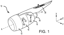
- Nacelle 10 for a propulsion system is illustrated, in accordance with various embodiments.
- Nacelle 10 may comprise an inlet 12, a fan cowl 14, a thrust reverser 16, and an exhaust system 18.
- Inlet 12, fan cowl 14, thrust reverser 16, and exhaust system 18 may be position around a central longitudinal axis A-A' of nacelle 10.
- Nacelle 10 provides smooth aerodynamic surfaces for airflow around and into a gas turbine engine surrounded by nacelle 10.
- Nacelle 10 may be coupled to a pylon 20.
- Pylon 20 may be configured to mount nacelle 10 and the gas turbine engine surrounded by nacelle 10 to an aircraft wing or aircraft body.
- Nacelle 10 may include one or more pressure-relief systems 100.
- fan cowl 14 and/or thrust reverser 16 may each include one or more pressure-relief systems 100.
- Pressure-relief systems 100 each include a pressure-relief door 101.
- Pressure-relief doors 101 may be hingedly connected. In this regard, pressure-relief doors 101 may pivot, or rotate, between an open position, wherein an interior of nacelle 10 radially inward of the pressure-relief door 101 is exposed and/or accessible, and a closed position, wherein the pressure-relief door 101 contacts and/or forms a sealing interface with the underlying nacelle component (e.g., fan cowl 14 or thrust reverser 16.).
- the underlying nacelle component e.g., fan cowl 14 or thrust reverser 16.
- Pressure-relief system 100 includes fastener assembly 102.
- Fastener assembly 100 is operably coupled to pressure-relief door 101 of pressure-relief system 100.
- fastener assembly 102 is configured to secure pressure-relief door 101 during normal operating conditions and release pressure-relief door 101 during an overloading event.
- Pressure-relief door 101 may be hingedly connected to an exterior panel 40 of nacelle 10 via a hinge joint 42.
- exterior panel 40 may form a portion of thrust reverser 16.
- exterior panel 40 may form a portion of fan cowl 14. It is further contemplated and understood that pressure-relief door 101 and fastener assembly 102 may be located at any location where a pressure-relief door is desired.
- an exterior (or radially outward) surface 44 of pressure-relief door 101 may be relatively flush or planar with an exterior surface 46 of exterior panel 40. Exterior surfaces 44, 46 are oriented generally away from central longitudinal axis A-A' of nacelle 10. In various embodiments, exterior surface 46 of exterior panel 40 may define an orifice configured to receive pressure-relief door 101. Pressure-relief door 101 may cover the orifice when in the closed position.
- fastener assembly 102 includes a housing 104.
- Housing 104 may be coupled to and/or extend from an interior (or radially inward) surface 50 of exterior panel 40. Interior surface 50 is opposite exterior surface 46 and is oriented generally toward central longitudinal axis A-A' of nacelle 10.
- housing 104 may have a generally cylindrical shape. Housing 104 may define a first cavity 106 and a second cavity 108. First cavity 106 is radially inward of second cavity 108. First and second cavities 106, 108 may each comprise a generally cylindrical shape. With momentary reference to FIG. 3 , a diameter D1 of first cavity 106 is less than a diameter D2 of second cavity 108.
- fastener assembly 102 includes a set of threaded members 110, including a first threaded member 110a and a second threaded member 110b.
- One or more biasing members 112 are coupled each of first threaded member 110a and second threaded member 110b.
- Biasing members 112 may also be coupled to housing 104. Biasing members 112 are configured to bias first threaded member 110a and second threaded member 110b in a radially inward direction.
- biasing members 112 apply a biasing force against first threaded member 110a and second threaded member 110b in a direction toward a radially inward (or exterior) surface 105 of housing 104 and away from second cavity 108 and pressure-relief door 101.
- biasing member 112 may comprise coil springs, each having a central axis C about which the biasing member 112 is coiled.
- First threaded member 110a and second threaded member 110b are configured to engage a threaded fastener 114.
- first threaded member 110a and second threaded member 110b each define a threaded surface 116a, 116b, respectively, configured to engage a threaded surface 118 of fastener 114.
- Fastener 114 is coupled to pressure-relief door 101.
- Fastener 114 may extend through an orifice 115 defined by exterior panel 40.
- Orifice 115 may comprise an oval or elliptical shape. The oval shape of orifice 115 may be configured to accommodate a tilting of fastener 114.
- fastener 114 may tilt, such that an angle of an axis of rotation R of fastener 114 relative to interior surface 50 changes.
- the oval shape of orifice 115 may be configured such that threaded surface 118 will not contact interior surface 50, thereby reducing a likelihood that an interference between fastener 114 and exterior panel 40 will prevent pressure-relief door 101 from translating to an open position.
- fastener 114 includes a collar 120 located proximate a head 122 of fastener 114. Collar 120 and head 122 may define a groove 124 configured to receive pressure-relief door 101. Stated differently, a diameter of fastener 114 at groove 124 is less than diameter of fastener 114 at collar 120 and at head 122. In various embodiments, fastener 114 may be coupled to pressure-relief door 101 by locating a portion of pressure-relief door 101 between collar 120 and head 122 of fastener 114.
- first and second threaded members 110a, 110b engage (i.e., are threaded to) fastener 114.
- first and second threaded members 110a, 110b engage (i.e., are threaded to) fastener 114.
- first and second threaded members 110a, 110b engage (i.e., are threaded to) fastener 114.
- first and second threaded members 110a, 110b is located in first cavity 106, such that an interference is formed between a wall 130 defining first cavity 106 (with momentary reference to FIG. 4B ) and first and second threaded members 110a, 110b.
- first and second threaded members 110a, 110b blocks or prevents first and second threaded members 110a, 110b from translating away from fastener 114 in a direction perpendicular to an axis of rotation R of fastener 114 (i.e., from translating in the direction of arrows 132 in FIG. 4 ).
- diameter D1 of first cavity 106 is selected such that when first and second threaded members 110a, 110b are located in first cavity 106, threaded surfaces 116a, 116b will engage threaded surface 118 of fastener 114.
- a pressure PI within an internal volume 160 defined, at least partially, by exterior panel 40 causes a radially outward force F NORMAL to be applied to pressure-relief door 101.
- F NORMAL radially outward force
- an overloading event such as a burst duct
- the pressure P2 within an internal volume 160 increases, such that a greater radially outward force F TRIGGER is applied to pressure-relief door 101.
- biasing members 112 are pre-loaded to prevent or reduce radially outward translation of fastener 114 during normal operating loads (i.e., at pressures less than or equal to pressure PI) and to extend in response to an overloading event (i.e., at pressures greater than or equal to pressure P2).
- biasing members 112 are pre-loaded with a force equal to or greater than force F NORMAL and less than force F TRIGGER .
- the pre-load may be established, during installation, by stretching biasing members 112 from the neutral position. The distance each biasing member 112 is stretched (i.e., initially displaced) is based on the spring rate of biasing member 112.
- Force F TRIGGER exceeding the biasing force applied to pressure-relief door 101 by biasing members 112 causes pressure-relief door 101 and fastener 114, which is attached to pressure-relief door 101, to translate in a radially outward direction and away from housing 104.
- fastener 114 In the locked position, fastener 114 translates in a radially outward direction and pulls, or translates, first and second threaded members 110a 110b in the radially outward direction. Stated differently, when first and second threaded members 110a, 110b are located at least partially within first cavity 106, fastener 114 is engaged with first and second threaded members 110a, 110b, such that radially outward translation of fastener 114 is transferred to first and second threaded members 110a, 110b and causes first and second threaded members 110a, 110b to translate in the radially outward direction.
- first and second threaded members 110a, 110b remain engaged with fastener 114 while first and second threaded members 110a, 110b are located at least partially with first cavity 106.
- first and second threaded members 110a, 110b translate to a location radially outward of first cavity 106, such that no portion of first and second threaded members 110a, 110b is located with first cavity 106, first and second threaded members 110a, 110b begin to translate away from one another.
- first and second threaded members 110a, 110b translate toward a wall 166 of second cavity 108a.
- first threaded member 110a will translate away from axis of rotation R of fastener 114, when a radially inward surface 168a of first threaded member 110a is located radially outward of wall 130 of first cavity 106
- second threaded member 110b will translate away from axis of rotation R of fastener 114, when a radially inward surface 168b of second threaded member 110b is located radially outward of wall 130 of first cavity 106.
- biasing members 112 may be oriented at an angle relative to wall 130 of first cavity, such that the biasing force applied by biasing members 112 works to translate first and second threaded members 110a, 110b toward wall 130.
- the imaginary center axis C about which each biasing member 112 is coiled, may be non-parallel to wall 130.
- imaginary center axes C of biasing members 112 may be oriented at an angle that is greater than or less than 90° relative to radially inward surface 168a, 168b of first and second threaded members 110a, 110b.
- housing 104 may define a first channel 170 and a second channel 172.
- First channel 170 and second channel 172 each extend from an exterior surface 107 of housing 104 to second cavity 108.
- exterior surface 107 is approximately normal to radially inward surface 105 of housing 104.
- “approximately” means ⁇ 10°.
- First channel 170 provides an access path to first threaded member 110a, when first threaded member 110a is located in second cavity 108.
- Second channel 172 provides an access path to second threaded member 102b, when second threaded member 102b is located in second cavity 108.
- An operator may translate first threaded member 102a and second threaded member 102b towards one another and back to the locked position by inserting a tool (e.g., a screwdriver) through first channel 170 and second channel 172.
- the tool may push first threaded member 102a and second threaded member 102b towards a center of housing 104.
- the biasing force of biasing members 112 may cause first and second threaded members 102a, 102b to translate radially inward and into first cavity 106.
- first and second threaded members 102a, 102b returned to first cavity 106, the operator may close and secure pressure-relief door 101 by threading fastener 114 into first and second threaded members 102a, 102b.
- housing 104 may include a stop 128.
- Stop 128 extends in a radially outward direction. Stop 128 is configured is configured to limit radially inward translation of fastener 114 and prevent first and second threaded members 110a from being unintentionally translated radially inward.
- housing 104 may further include a clocking protrusion 129.
- Clocking protrusion may extend from wall 130.
- the clocking protrusion 129 may be configured to form an interreference with first threaded member 110a and/or second threaded member 110b to prevent or reduce rotation of first threaded member 110a and second threaded member 110b about axis R when fastener 114 is installed.
- a plug may be located in first and second channels 170, 172 to prevent fluid and/or or debris from entering housing 104.
- first and second channels 170, 172 may be threaded, such that a threaded plug may be inserted in to first and second channels 170, 172.
- Force F is the load applied by fastener 114.
- the load applied by fastener 114 may be determined based on the load experience by pressure-relief door 101, the configuration of hinge joint 42, and the number of fastener assemblies 102 and fasteners 114 per pressure-relief door 101.
- force F may be 25% of the total load applied to pressure-relief door 101, where pressure-relief door 101 is attached via two hinges and included two fastener assemblies 102 with the load applied evenly over two fasteners 114.
- force F may be equal to F NORMAL .
- force F may be equal to F TRIGGER .
- Spring force F k is the force applied by the biasing members 112.
- Housing force N is the normal force applied housing 104.
- Friction force F f is the force due to friction between first threaded member 110a and wall 130 of first cavity 106.
- Spring angle theta ( ⁇ ) is the angle formed by spring axis C and radially inward surface 168a of first threaded member 110a.
- the initial displacement may determine a desired spring pre-load F l for biasing members 112 to prevent radially outward translation of first threaded member 110a during normal operating loads (i.e., at pressures less than or equal to pressure PI).
- spring force F k of biasing member 112 is equal to the product of spring rate k and initial displacement ⁇ o , as first threaded member 110a will not yet have stretched biasing member 112.
- biasing member 112 may also be selected based on a desired trigger load F c .
- Desired trigger load F c represents the load at which fastener 114 will be released.
- first and second threaded members 110a, 110b will have translated below first cavity 106 such that first and second threaded members 110a, 110b translate away from fastener 114 and into second cavity 108.
- ⁇ o L f ⁇ L o F c sin ⁇ + ⁇ cos ⁇ F l sin ⁇ + ⁇ cos ⁇ ⁇ 1
- Initial displacement ⁇ o from equation 8 may be substituted into equation 7 to solve for spring rate k.
- Spring rate k represents a total spring rate acting on first and second threaded members 110a, 110b, which may be distributed over several biasing members 112. Adjusting the spring rate k and/or initial displacement ⁇ o of biasing members 112 allows fastener assembly 102 to be tuned such that pressure-relief door 101 is secured at normal operating loads and released at a trigger load.
- spring rate k and/or initial displacement ⁇ o of biasing members 112 is/are selected such that pressure-relief door 101 remains in the closed position at loads less than a first preselected load (i.e., a trigger load) and translates to the open position at loads greater than the first preselected load (i.e., the trigger load).
- first and second threaded members 110a, 110b in first cavity 106 are illustrated, in accordance with various embodiment.
- the clearance may be configured to avoid opposing sides of first and second threaded members 110a, 110b simultaneously contacting wall 130 of first cavity 106 as pressure-relief door 101 opens and rotates about hinge joint 42.
- an angle beta ( ⁇ ) of pressure-relief door 101, relative to a radially outward surface 176 of housing 104 is illustrated.
- Radially outward surface 176 may extend between wall 130 of first cavity 106, with momentary reference to FIG. 3 , and wall 166 of second cavity 108, with momentary reference to FIG. 3 .
- fastener 114 may release from first and second threaded members 110a, 110b, when pressure-relief door 101 is oriented at angle beta ( ⁇ ).
- radially inward surfaces 168a, 168b of first and second threaded members 110a, 110b may be radially outward of radially outward surface 176.
- a clearance S associated with avoiding opposing sides of first and second threaded members 110a, 110b simultaneously contacting wall 130 of first cavity 106 is determined based on the sum of a distance d1 and a distance d2.
- Distance d1 is measured between a surface 180 of wall 130 and an edge 182 of first and second threaded members 110a, 110b.
- Surface 180 of wall 130 is a surface of wall 130 that is distal, or furthest from, hinge joint 42.
- Edge 182 is a radially inward edge of first and second threaded members 110a, 110b that is located proximate, or closest, to hinge joint 42.
- Distance d2 may be calculated based on a distance d3 between radially outward surface 176 of housing 104 and an imaginary axis 184.
- Imaginary axis 184 is parallel to radially outward surface 176 and extends from radially inward edge 182.
- diameter D1 of first cavity is selected to be greater than clearance S to avoid opposing sides of first and second threaded members 110a, 110b simultaneously contacting wall 130.
- references to "one embodiment”, “an embodiment”, “various embodiments”, etc. indicate that the embodiment described may include a particular feature, structure, or characteristic, but every embodiment may not necessarily include the particular feature, structure, or characteristic. Moreover, such phrases are not necessarily referring to the same embodiment. Further, when a particular feature, structure, or characteristic is described in connection with an embodiment, it is submitted that it is within the knowledge of one skilled in the art to affect such feature, structure, or characteristic in connection with other embodiments whether or not explicitly described. After reading the description, it will be apparent to one skilled in the relevant art(s) how to implement the disclosure in alternative embodiments.
Landscapes
- Engineering & Computer Science (AREA)
- General Engineering & Computer Science (AREA)
- Mechanical Engineering (AREA)
- Aviation & Aerospace Engineering (AREA)
- Pressure Vessels And Lids Thereof (AREA)
Abstract
Description
- The present disclosure relates to aircraft nacelles, and more particularly to a fastener assembly for nacelle pressure-relief doors.
- A nacelle for a propulsion system typically includes an inlet, a fan cowl, a thrust reverser, and an exhaust section. The nacelle is typically mounted to a wing or a fuselage of an aircraft via a pylon. The nacelle may provide smooth, aerodynamic surfaces for airflow around and into a gas turbine engine located within the nacelle. Pressurized ducting may be located throughout the nacelle and/or defined by components of the nacelle. Nacelles may include pressure-relief doors configured to open in response to an overloading event, such as a burst duct. The pressure-relief doors need to be able to open to relieve pressure, but also remain securely closed during normal operation.
- A fastener assembly is disclosed herein. In accordance with various embodiments, the fastener assembly may comprise a housing defining a first cavity and a second cavity. A first threaded member may be located within the housing. A second threaded member may be located within the housing. A first biasing member may be coupled to the first threaded member. A second biasing member may be coupled to the second threaded member.
- In various embodiments, the first biasing member may apply a first biasing force against the first threaded member in a direction away from the second cavity. The second biasing member may apply a second biasing force against the second threaded member in the direction away from the second cavity.
- In various embodiments, a diameter of the first cavity may be less than a diameter of the second cavity. In various embodiments, the fastener assembly may further comprise a fastener configured to engage the first threaded member and the second threaded member.
- In various embodiments, the fastener may comprise a collar and a head. The collar and the head may define a groove. In various embodiments, the first biasing member may be oriented at an angle greater than or less than 90° relative to a radially inward surface of the first biasing member.
- In various embodiments, the housing may define a first channel extending to from an exterior surface of the housing to the second cavity.
- A pressure-relief system is also disclosed herein. In accordance with various embodiments, the pressure-relief system may comprise a pressure-relief door and a fastener assembly configured to secure and release the pressure-relief door. The fastener assembly may comprise a housing defining a first cavity and a second cavity, a first threaded member located within the housing, a second threaded member located within the housing, a first biasing member coupled to the first threaded member, and a second biasing member coupled to the second threaded member.
- In various embodiments, a fastener may be coupled to the pressure-relief door. The first threaded member and the second threaded member may be configured to engage the fastener. In various embodiments, the fastener may comprise a collar and a head. The pressure-relief door may be located between the collar and the head.
- In various embodiments, the first biasing member may apply a first biasing force against the first threaded member in a direction away from the second cavity. The second biasing member may apply a second biasing force against the second threaded member in the direction away from the second cavity.
- In various embodiments, the first biasing member may be oriented at an angle greater than or less than 90° relative to a radially inward surface of the first biasing member. In various embodiments, a diameter of the first cavity may be less than a diameter of the second cavity.
- In various embodiments, the second cavity may be located closer to the pressure-relief door as compared to the first cavity. In various embodiments, the housing may define a channel extending from an exterior surface of the housing to the second cavity.
- A nacelle is also disclosed herein. In accordance with various embodiments, the nacelle may comprise an exterior panel, a pressure-relief door hingedly coupled to the exterior panel, and a fastener assembly configured to secure and release the pressure-relief door. The fastener assembly may comprise a housing defining a first cavity and a second cavity, a first threaded member located within the housing, a second threaded member located within the housing, a first biasing member coupled to the first threaded member, and a second biasing member coupled to the second threaded member.
- In various embodiments, a fastener may be coupled to the pressure-relief door. The first threaded member and the second threaded member may be configured to engage the fastener.
- In various embodiments, the first biasing member may apply a first biasing force against the first threaded member in a direction away from the second cavity. The second biasing member may apply a second biasing force against the second threaded member in the direction away from the second cavity.
- In various embodiments, a diameter of the first cavity may be less than a diameter of the second cavity. In various embodiments, the nacelle may further comprise at least one of a fan cowl or a thrust reverser. The least one of the fan cowl or the thrust reverser may include the exterior panel.
- The foregoing features and elements may be combined in various combinations without exclusivity, unless expressly indicated herein otherwise. These features and elements as well as the operation of the disclosed embodiments will become more apparent in light of the following description and accompanying drawings.
- The subject matter of the present disclosure is particularly pointed out and distinctly claimed in the concluding portion of the specification. A more complete understanding of the present disclosure, however, may best be obtained by referring to the detailed description and claims when considered in connection with the drawing figures, wherein like numerals denote like elements.
-
FIG. 1 illustrates a perspective view of a nacelle, in accordance with various embodiments; -
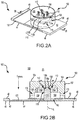
FIG. 2A illustrates a perspective view of a fastener assembly for a pressure-relief system with a pressure-relief door of the system in a closed position, in accordance with various embodiments; -
FIG. 2B illustrates a cross-section view, taken along theline 2B-2B inFIG. 2A , of a fastener assembly for a pressure-relief system with a pressure-relief door of the system in a closed position, in accordance with various embodiments; -
FIG 3 illustrates a cross-section view of a fastener assembly for a pressure-relief system with a pressure-relief door of the system in a position where the pressure-relief door has begun to open and the fastener assembly is still in a locked state, in accordance with various embodiments; -
FIG. 4A illustrates a perspective view of a fastener assembly for a pressure-relief system with the fastener assembly in an unlocked state and a pressure-relief door of the system in an open position, in accordance with various embodiments; -
FIG. 4B illustrates a cross-section view, taken along theline 4B-4B inFIG. 4A , of a fastener assembly for a pressure-relief system with the fastener assembly in an unlocked state and a pressure-relief door of the system in an open position, in accordance with various embodiments; -
FIG. 5 illustrates forces applied to a threaded member of a fastener assembly, in accordance with various embodiments; and -
FIGs. 6A and 6B illustrate clearances associated with avoiding fastener assembly jamming, in accordance with various embodiments. - The detailed description of various embodiments herein makes reference to the accompanying drawings, which show various embodiments by way of illustration. While these various embodiments are described in sufficient detail to enable those skilled in the art to practice the inventions, it should be understood that other embodiments may be realized and that logical, chemical and mechanical changes may be made without departing from the spirit and scope of the inventions. Thus, the detailed description herein is presented for purposes of illustration only and not of limitation. For example, the steps recited in any of the method or process descriptions may be executed in any order and are not necessarily limited to the order presented. Furthermore, any reference to singular includes plural embodiments, and any reference to more than one component or step may include a singular embodiment or step. Also, any reference to attached, fixed, connected or the like may include permanent, removable, temporary, partial, full and/or any other possible attachment option. Additionally, any reference to without contact (or similar phrases) may also include reduced contact or minimal contact.
- Surface shading and/or crosshatching lines may be used throughout the figures to denote different parts, but not necessarily to denote the same or different materials. Throughout the present disclosure, like reference numbers denote like elements. Accordingly, elements with like element numbering may be shown in the figures, but may not necessarily be repeated herein for the sake of clarity.
- As used herein, "aft" refers to the direction associated with the tail (e.g., the back end) of an aircraft, or generally, to the direction of exhaust of the gas turbine. As used herein, "forward" refers to the direction associated with the nose (e.g., the front end) of an aircraft, or generally, to the direction of flight or motion. As used herein, "a radially outward direction" refers to a direction away from a central longitudinal axis of a nacelle. As used herein, "a radially inward direction" refers to a direction toward from the central longitudinal axis of the nacelle. A first component that is "radially inward" of a second component means that the first component is positioned closer to the central longitudinal axis of the nacelle than the second component. A first component that is "radially outward" of a second component means that the first component is positioned at a greater distance away from a central longitudinal axis of the nacelle. A first component that is "radially inward" of a second component means that the first component is positioned closer to the central longitudinal axis of the nacelle than the second component. The terminology "radially outward" and "radially inward" may also be used relative to reference axes other than the central longitudinal axis of the nacelle.
- Fastener assemblies, as described herein, may be configured to secure a pressure-relief door during normal operating conditions and allow the pressure-relief door to open in response to a pressure increase. In accordance with various embodiments, the fastener assembly may include a threaded fastener coupled to the pressure-relief door and configured to engage a set of threaded members. During normal operation, the threaded fastener may engage the threaded members and retain the pressure-relief door in a closed position. During an overloading event, the threaded members may separate and release the fastener, thereby allowing the pressure-relief door to translate to an open position.
- Referring to
FIG. 1 , anacelle 10 for a propulsion system is illustrated, in accordance with various embodiments.Nacelle 10 may comprise aninlet 12, afan cowl 14, athrust reverser 16, and anexhaust system 18.Inlet 12,fan cowl 14, thrustreverser 16, andexhaust system 18 may be position around a central longitudinal axis A-A' ofnacelle 10.Nacelle 10 provides smooth aerodynamic surfaces for airflow around and into a gas turbine engine surrounded bynacelle 10.Nacelle 10 may be coupled to apylon 20.Pylon 20 may be configured to mountnacelle 10 and the gas turbine engine surrounded bynacelle 10 to an aircraft wing or aircraft body. -
Nacelle 10 may include one or more pressure-relief systems 100. For example,fan cowl 14 and/or thrustreverser 16 may each include one or more pressure-relief systems 100. Pressure-relief systems 100 each include a pressure-relief door 101. Pressure-relief doors 101 may be hingedly connected. In this regard, pressure-relief doors 101 may pivot, or rotate, between an open position, wherein an interior ofnacelle 10 radially inward of the pressure-relief door 101 is exposed and/or accessible, and a closed position, wherein the pressure-relief door 101 contacts and/or forms a sealing interface with the underlying nacelle component (e.g.,fan cowl 14 or thrustreverser 16.). - Referring to
FIGs. 2A and 2B , and with continued reference toFIG. 1 , afastener assembly 102 of pressure-relief system 100 is illustrated, in accordance with various embodiments. Pressure-relief system 100 includesfastener assembly 102.Fastener assembly 100 is operably coupled to pressure-relief door 101 of pressure-relief system 100. In this regard,fastener assembly 102 is configured to secure pressure-relief door 101 during normal operating conditions and release pressure-relief door 101 during an overloading event. Pressure-relief door 101 may be hingedly connected to anexterior panel 40 ofnacelle 10 via a hinge joint 42. In various embodiments,exterior panel 40 may form a portion ofthrust reverser 16. In various embodiments,exterior panel 40 may form a portion offan cowl 14. It is further contemplated and understood that pressure-relief door 101 andfastener assembly 102 may be located at any location where a pressure-relief door is desired. - In various embodiments, when pressure-
relief door 101 is in the closed position, as illustrated inFIGs. 2A and 2B , an exterior (or radially outward)surface 44 of pressure-relief door 101 may be relatively flush or planar with anexterior surface 46 ofexterior panel 40. Exterior surfaces 44, 46 are oriented generally away from central longitudinal axis A-A' ofnacelle 10. In various embodiments,exterior surface 46 ofexterior panel 40 may define an orifice configured to receive pressure-relief door 101. Pressure-relief door 101 may cover the orifice when in the closed position. - In accordance with various embodiments,
fastener assembly 102 includes ahousing 104.Housing 104 may be coupled to and/or extend from an interior (or radially inward)surface 50 ofexterior panel 40.Interior surface 50 is oppositeexterior surface 46 and is oriented generally toward central longitudinal axis A-A' ofnacelle 10. - In various embodiments,
housing 104 may have a generally cylindrical shape.Housing 104 may define afirst cavity 106 and asecond cavity 108.First cavity 106 is radially inward ofsecond cavity 108. First andsecond cavities FIG. 3 , a diameter D1 offirst cavity 106 is less than a diameter D2 ofsecond cavity 108. - In accordance with various embodiments,
fastener assembly 102 includes a set of threadedmembers 110, including a first threadedmember 110a and a second threadedmember 110b. One ormore biasing members 112 are coupled each of first threadedmember 110a and second threadedmember 110b. Biasingmembers 112 may also be coupled tohousing 104. Biasingmembers 112 are configured to bias first threadedmember 110a and second threadedmember 110b in a radially inward direction. In this regard, biasingmembers 112 apply a biasing force against first threadedmember 110a and second threadedmember 110b in a direction toward a radially inward (or exterior)surface 105 ofhousing 104 and away fromsecond cavity 108 and pressure-relief door 101. In various embodiments, biasingmember 112 may comprise coil springs, each having a central axis C about which the biasingmember 112 is coiled. - First threaded
member 110a and second threadedmember 110b are configured to engage a threadedfastener 114. In this regard, first threadedmember 110a and second threadedmember 110b each define a threadedsurface surface 118 offastener 114.Fastener 114 is coupled to pressure-relief door 101.Fastener 114 may extend through anorifice 115 defined byexterior panel 40.Orifice 115 may comprise an oval or elliptical shape. The oval shape oforifice 115 may be configured to accommodate a tilting offastener 114. For example, as pressure-relief door 101 pivots about hinge joint 42,fastener 114 may tilt, such that an angle of an axis of rotation R offastener 114 relative tointerior surface 50 changes. The oval shape oforifice 115 may be configured such that threadedsurface 118 will not contactinterior surface 50, thereby reducing a likelihood that an interference betweenfastener 114 andexterior panel 40 will prevent pressure-relief door 101 from translating to an open position. - With momentary reference to
FIG. 3 , in various embodiments,fastener 114 includes acollar 120 located proximate ahead 122 offastener 114.Collar 120 andhead 122 may define agroove 124 configured to receive pressure-relief door 101. Stated differently, a diameter offastener 114 atgroove 124 is less than diameter offastener 114 atcollar 120 and athead 122. In various embodiments,fastener 114 may be coupled to pressure-relief door 101 by locating a portion of pressure-relief door 101 betweencollar 120 andhead 122 offastener 114. - With reference to
FIGs. 2A and 2B andFIG. 3 , whenfastener assembly 102 is in a locked state, as shown inFIGs. 2A, 2B , and3 , first and second threadedmembers fastener 114. In the locked state, at least, a portion of first and second threadedmembers first cavity 106, such that an interference is formed between awall 130 defining first cavity 106 (with momentary reference toFIG. 4B ) and first and second threadedmembers wall 130 and first and second threadedmembers members fastener 114 in a direction perpendicular to an axis of rotation R of fastener 114 (i.e., from translating in the direction ofarrows 132 inFIG. 4 ). In accordance with various embodiments, diameter D1 offirst cavity 106 is selected such that when first and second threadedmembers first cavity 106, threadedsurfaces surface 118 offastener 114. - During normal operating conditions, a pressure PI within an
internal volume 160 defined, at least partially, byexterior panel 40 causes a radially outward force FNORMAL to be applied to pressure-relief door 101. During an overloading event, such as a burst duct, the pressure P2 within aninternal volume 160 increases, such that a greater radially outward force FTRIGGER is applied to pressure-relief door 101. In accordance with various embodiments, biasingmembers 112 are pre-loaded to prevent or reduce radially outward translation offastener 114 during normal operating loads (i.e., at pressures less than or equal to pressure PI) and to extend in response to an overloading event (i.e., at pressures greater than or equal to pressure P2). In this regard, biasingmembers 112 are pre-loaded with a force equal to or greater than force FNORMAL and less than force FTRIGGER. The pre-load may be established, during installation, by stretching biasingmembers 112 from the neutral position. The distance each biasingmember 112 is stretched (i.e., initially displaced) is based on the spring rate of biasingmember 112. Force FTRIGGER exceeding the biasing force applied to pressure-relief door 101 by biasingmembers 112, causes pressure-relief door 101 andfastener 114, which is attached to pressure-relief door 101, to translate in a radially outward direction and away fromhousing 104. In the locked position,fastener 114 translates in a radially outward direction and pulls, or translates, first and second threadedmembers 110a 110b in the radially outward direction. Stated differently, when first and second threadedmembers first cavity 106,fastener 114 is engaged with first and second threadedmembers fastener 114 is transferred to first and second threadedmembers members - With combined reference to
FIG. 3 andFIGs. 4A and 4B , as pressure-relief door 101 translates in the radially outward direction (i.e. in the direction of arrow 162), first and second threadedmembers fastener 114 while first and second threadedmembers first cavity 106. When first and second threadedmembers first cavity 106, such that no portion of first and second threadedmembers first cavity 106, first and second threadedmembers members wall 130 of first cavity is removed, first and second threadedmembers wall 166 of second cavity 108a. Stated yet another way, first threadedmember 110a will translate away from axis of rotation R offastener 114, when a radiallyinward surface 168a of first threadedmember 110a is located radially outward ofwall 130 offirst cavity 106, and second threadedmember 110b will translate away from axis of rotation R offastener 114, when a radiallyinward surface 168b of second threadedmember 110b is located radially outward ofwall 130 offirst cavity 106. - As first and second threaded
members surfaces surface 118 offastener 114, thereby releasingfastener 114 and allowing pressure-relief door 101 to pivot to a fully-open position. In various embodiments, biasingmembers 112 may be oriented at an angle relative to wall 130 of first cavity, such that the biasing force applied by biasingmembers 112 works to translate first and second threadedmembers wall 130. Stated differently, the imaginary center axis C, about which each biasingmember 112 is coiled, may be non-parallel towall 130. Stated yet another way, imaginary center axes C of biasingmembers 112 may be oriented at an angle that is greater than or less than 90° relative to radiallyinward surface members - In various embodiments,
housing 104 may define afirst channel 170 and asecond channel 172.First channel 170 andsecond channel 172 each extend from anexterior surface 107 ofhousing 104 tosecond cavity 108. In various embodiments,exterior surface 107 is approximately normal to radiallyinward surface 105 ofhousing 104. As used in the previous context only, "approximately" means ± 10°.First channel 170 provides an access path to first threadedmember 110a, when first threadedmember 110a is located insecond cavity 108.Second channel 172 provides an access path to second threaded member 102b, when second threaded member 102b is located insecond cavity 108. An operator may translate first threaded member 102a and second threaded member 102b towards one another and back to the locked position by inserting a tool (e.g., a screwdriver) throughfirst channel 170 andsecond channel 172. The tool may push first threaded member 102a and second threaded member 102b towards a center ofhousing 104. Once the interference between a radiallyoutward surface 176 ofhousing 104 and radiallyinward surfaces members 112 may cause first and second threaded members 102a, 102b to translate radially inward and intofirst cavity 106. With first and second threaded members 102a, 102b returned tofirst cavity 106, the operator may close and secure pressure-relief door 101 by threadingfastener 114 into first and second threaded members 102a, 102b. - In various embodiments,
housing 104 may include astop 128. Stop 128 extends in a radially outward direction. Stop 128 is configured is configured to limit radially inward translation offastener 114 and prevent first and second threadedmembers 110a from being unintentionally translated radially inward. - In various embodiments,
housing 104 may further include aclocking protrusion 129. Clocking protrusion may extend fromwall 130. The clockingprotrusion 129 may be configured to form an interreference with first threadedmember 110a and/or second threadedmember 110b to prevent or reduce rotation of first threadedmember 110a and second threadedmember 110b about axis R whenfastener 114 is installed. - In various embodiments, a plug may be located in first and
second channels housing 104. In various embodiments, first andsecond channels second channels - With reference to
FIG. 5 , and continuing reference toFIGs. 2A, 2B , andFIG. 3 , various forces acting on first threadedmember 110a are illustrated, in accordance with various embodiments. Force F is the load applied byfastener 114. The load applied byfastener 114 may be determined based on the load experience by pressure-relief door 101, the configuration of hinge joint 42, and the number offastener assemblies 102 andfasteners 114 per pressure-relief door 101. For example, force F may be 25% of the total load applied to pressure-relief door 101, where pressure-relief door 101 is attached via two hinges and included twofastener assemblies 102 with the load applied evenly over twofasteners 114. - During normal operating conditions, force F may be equal to FNORMAL. During an overloading event, force F may be equal to FTRIGGER. Spring force Fk is the force applied by the biasing
members 112. Housing force N is the normal force appliedhousing 104. Friction force Ff is the force due to friction between first threadedmember 110a andwall 130 offirst cavity 106. Spring angle theta (θ) is the angle formed by spring axis C and radiallyinward surface 168a of first threadedmember 110a. - The sum of the forces in the x direction of the provide XY axis may be determined from below equation 1:

- The sum of the forces in the y direction of the provide XY axis may be determined from below equation 2:

- Friction force Ff can be determined from below equation 3:

member 112, δo is the initial displacement of the biasingmember 112 as measured along axis C of biasingmember 112, and µ is the friction constant ofhousing 104. The initial displacement may determine a desired spring pre-load Fl for biasingmembers 112 to prevent radially outward translation of first threadedmember 110a during normal operating loads (i.e., at pressures less than or equal to pressure PI). At any F below the desired pre-load Fl, spring force Fk of biasingmember 112 is equal to the product of spring rate k and initial displacement δo , as first threadedmember 110a will not yet have stretched biasingmember 112. The desired spring pre-load Fl , can be determined using below equation 4:
- The specifications of biasing
member 112 may also be selected based on a desired trigger load Fc . Desired trigger load Fc represents the load at whichfastener 114 will be released. At desired trigger load Fc , first and second threadedmembers first cavity 106 such that first and second threadedmembers fastener 114 and intosecond cavity 108. Desired trigger load Fc may be determine using below equation 5:
member 112 and α represents the angle formed by axis C of biasingmember 112 and radiallyinward surface 168a after displacement of biasingmember 112. - The final displacement δf can be determined using below equation 6:

member 112 and Lo represents the initial length of the biasingmember 112. - Using above equations 4 and 5, spring rate k can be determined using below equation 7:

- Using above equations 4 and 5 and 6, an initial displacement δo of biasing
member 112 can be determined using below equation 8:
- Initial displacement δo from equation 8 may be substituted into equation 7 to solve for spring rate k. Spring rate k represents a total spring rate acting on first and second threaded
members members 112. Adjusting the spring rate k and/or initial displacement δo of biasingmembers 112 allowsfastener assembly 102 to be tuned such that pressure-relief door 101 is secured at normal operating loads and released at a trigger load. Stated differently, spring rate k and/or initial displacement δo of biasingmembers 112 is/are selected such that pressure-relief door 101 remains in the closed position at loads less than a first preselected load (i.e., a trigger load) and translates to the open position at loads greater than the first preselected load (i.e., the trigger load). - With reference to
FIGs. 6A and 6B , clearances associated with avoiding a jamming of first and second threadedmembers first cavity 106 are illustrated, in accordance with various embodiment. The clearance may be configured to avoid opposing sides of first and second threadedmembers wall 130 offirst cavity 106 as pressure-relief door 101 opens and rotates about hinge joint 42. - In
FIG. 6A , an angle beta (β) of pressure-relief door 101, relative to a radiallyoutward surface 176 ofhousing 104 is illustrated. Radiallyoutward surface 176 may extend betweenwall 130 offirst cavity 106, with momentary reference toFIG. 3 , andwall 166 ofsecond cavity 108, with momentary reference toFIG. 3 . In various embodiments,fastener 114 may release from first and second threadedmembers relief door 101 is oriented at angle beta (β). Stated differently, at angle beta (β), radiallyinward surfaces members outward surface 176. In accordance with various embodiments, angle beta β may be determined using below equation 9:
relief door 101 as measured between hinge joint 42 and rotation axis R offastener 114, and h is the height of first and second threadedmembers inward surfaces members relief door 101. - In accordance with various embodiments, when pressure-
relief door 101 is oriented at angle beta (β), a clearance S associated with avoiding opposing sides of first and second threadedmembers wall 130 offirst cavity 106 is determined based on the sum of a distance d1 and a distance d2. Distance d1 is measured between asurface 180 ofwall 130 and anedge 182 of first and second threadedmembers Surface 180 ofwall 130 is a surface ofwall 130 that is distal, or furthest from, hinge joint 42.Edge 182 is a radially inward edge of first and second threadedmembers outward surface 176 ofhousing 104 and animaginary axis 184.Imaginary axis 184 is parallel to radiallyoutward surface 176 and extends from radiallyinward edge 182. In accordance with various embodiment, clearance S may be determined using below equation 10:
members surfaces surface 118 of fastener 114), and angle beta (β) is the angle formed by pressure-relief door 101 and radiallyoutward surface 176 ofhousing 104. - With combined reference to
FIG. 3 andFIG. 6B , in accordance with various embodiments, diameter D1 of first cavity is selected to be greater than clearance S to avoid opposing sides of first and second threadedmembers wall 130. - Benefits, other advantages, and solutions to problems have been described herein with regard to specific embodiments. Furthermore, the connecting lines shown in the various figures contained herein are intended to represent exemplary functional relationships and/or physical couplings between the various elements. It should be noted that many alternative or additional functional relationships or physical connections may be present in a practical system. However, the benefits, advantages, solutions to problems, and any elements that may cause any benefit, advantage, or solution to occur or become more pronounced are not to be construed as critical, required, or essential features or elements of the disclosure.
- The scope of the disclosure is accordingly to be limited by nothing other than the appended claims, in which reference to an element in the singular is not intended to mean "one and only one" unless explicitly so stated, but rather "one or more." It is to be understood that unless specifically stated otherwise, references to "a," "an," and/or "the" may include one or more than one and that reference to an item in the singular may also include the item in the plural. All ranges and ratio limits disclosed herein may be combined.
- Moreover, where a phrase similar to "at least one of A, B, and C" is used in the claims, it is intended that the phrase be interpreted to mean that A alone may be present in an embodiment, B alone may be present in an embodiment, C alone may be present in an embodiment, or that any combination of the elements A, B and C may be present in a single embodiment; for example, A and B, A and C, B and C, or A and B and C. Elements and steps in the figures are illustrated for simplicity and clarity and have not necessarily been rendered according to any particular sequence. For example, steps that may be performed concurrently or in different order are illustrated in the figures to help to improve understanding of embodiments of the present disclosure.
- Systems, methods and apparatus are provided herein. In the detailed description herein, references to "one embodiment", "an embodiment", "various embodiments", etc., indicate that the embodiment described may include a particular feature, structure, or characteristic, but every embodiment may not necessarily include the particular feature, structure, or characteristic. Moreover, such phrases are not necessarily referring to the same embodiment. Further, when a particular feature, structure, or characteristic is described in connection with an embodiment, it is submitted that it is within the knowledge of one skilled in the art to affect such feature, structure, or characteristic in connection with other embodiments whether or not explicitly described. After reading the description, it will be apparent to one skilled in the relevant art(s) how to implement the disclosure in alternative embodiments.
- Furthermore, no element, component, or method step in the present disclosure is intended to be dedicated to the public regardless of whether the element, component, or method step is explicitly recited in the claims. As used herein, the terms "comprises", "comprising", or any other variation thereof, are intended to cover a non-exclusive inclusion, such that a process, method, article, or apparatus that comprises a list of elements does not include only those elements but may include other elements not expressly listed or inherent to such process, method, article, or apparatus.
Claims (15)
- A fastener assembly, comprising:a housing defining a first cavity and a second cavity;a first threaded member located within the housing;a second threaded member located within the housing;a first biasing member coupled to the first threaded member; anda second biasing member coupled to the second threaded member.
- The fastener assembly of claim 1, wherein the first biasing member applies a first biasing force against the first threaded member in a direction away from the second cavity, and wherein the second biasing member applies a second biasing force against the second threaded member in the direction away from the second cavity.
- The fastener assembly of claim 1 or 2, wherein a diameter of the first cavity is less than a diameter of the second cavity.
- The fastener assembly of claim 3, further comprising a fastener configured to engage the first threaded member and the second threaded member.
- The fastener assembly of claim 4, wherein the fastener comprises a collar and a head, and wherein the collar and the head define a groove.
- The fastener assembly of any preceding claim, wherein the first biasing member is oriented at an angle greater than or less than 90° relative to a radially inward surface of the first biasing member.
- The fastener assembly of any preceding claim, wherein the housing defines a first channel extending to from an exterior surface of the housing to the second cavity.
- A pressure-relief system, comprising:a pressure-relief door; anda fastener assembly configured to secure and release the pressure-relief door, the fastener assembly comprising:a housing defining a first cavity and a second cavity;a first threaded member located within the housing;a second threaded member located within the housing;a first biasing member coupled to the first threaded member; anda second biasing member coupled to the second threaded member.
- The pressure-relief system of claim 8, further comprising a fastener coupled to the pressure-relief door, wherein the first threaded member and the second threaded member are configured to engage the fastener.
- The pressure-relief system of claim 9, wherein the fastener comprises a collar and a head, and wherein the pressure-relief door is located between the collar and the head.
- The pressure-relief system of claim 8, 9 or 10, wherein the first biasing member applies a first biasing force against the first threaded member in a direction away from the second cavity, and wherein the second biasing member applies a second biasing force against the second threaded member in the direction away from the second cavity, wherein the first biasing member is oriented at an angle greater than or less than 90° relative to a radially inward surface of the first biasing member.
- The pressure-relief system of any of claims 8 to 11, wherein a diameter of the first cavity is less than a diameter of the second cavity, wherein the second cavity is located closer to the pressure-relief door as compared to the first cavity.
- The pressure-relief system of any of claims 8 to 12, wherein the housing defines a channel extending from an exterior surface of the housing to the second cavity.
- A nacelle, comprising:an exterior panel;a pressure-relief door hingedly coupled to the exterior panel; anda fastener assembly configured to secure and release the pressure-relief door, the fastener assembly comprising:a housing defining a first cavity and a second cavity;a first threaded member located within the housing;a second threaded member located within the housing;a first biasing member coupled to the first threaded member; anda second biasing member coupled to the second threaded member.
- The nacelle of claim 14, wherein:the nacelle further comprises a fastener coupled to the pressure-relief door, wherein the first threaded member and the second threaded member are configured to engage the fastener; and/orthe first biasing member applies a first biasing force against the first threaded member in a direction away from the second cavity, and wherein the second biasing member applies a second biasing force against the second threaded member in the direction away from the second cavity; and/orwherein a diameter of the first cavity is less than a diameter of the second cavity; and/orthe nacelle further comprises at least one of a fan cowl or a thrust reverser, wherein the least one of the fan cowl or the thrust reverser includes the exterior panel.
Applications Claiming Priority (1)
| Application Number | Priority Date | Filing Date | Title |
|---|---|---|---|
| US16/429,990 US11143223B2 (en) | 2019-06-03 | 2019-06-03 | Fastener assembly for nacelle pressure-relief doors |
Publications (2)
| Publication Number | Publication Date |
|---|---|
| EP3748174A1 true EP3748174A1 (en) | 2020-12-09 |
| EP3748174B1 EP3748174B1 (en) | 2023-09-06 |
Family
ID=68917645
Family Applications (1)
| Application Number | Title | Priority Date | Filing Date |
|---|---|---|---|
| EP19216587.6A Active EP3748174B1 (en) | 2019-06-03 | 2019-12-16 | Fastener assembly for nacelle pressure-relief doors |
Country Status (2)
| Country | Link |
|---|---|
| US (1) | US11143223B2 (en) |
| EP (1) | EP3748174B1 (en) |
Families Citing this family (1)
| Publication number | Priority date | Publication date | Assignee | Title |
|---|---|---|---|---|
| FR3156758A1 (en) * | 2023-12-19 | 2025-06-20 | Safran Nacelles | Assembly comprising a fixed surface and a moving surface of an aircraft. |
Citations (8)
| Publication number | Priority date | Publication date | Assignee | Title |
|---|---|---|---|---|
| DE1928490A1 (en) * | 1968-06-04 | 1970-01-22 | Akira Ito | Lock nut arrangement |
| US5902085A (en) * | 1997-01-20 | 1999-05-11 | Emhart Inc. | Press type nut |
| DE69506249T2 (en) * | 1994-06-07 | 1999-05-27 | Hedley Purvis Ltd., Morpeth, Northumberland | IMPROVED QUICK-MOUNT NUT |
| US7798893B2 (en) * | 2006-01-19 | 2010-09-21 | Fike Corporation | Full opening and reclosable explosion vent apparatus |
| US8136544B2 (en) * | 2006-08-15 | 2012-03-20 | Babcock & Wilcox Power Generation Group, Inc. | Sealing arrangement with a segmented seal and pressure relief |
| US20130256482A1 (en) * | 2012-03-28 | 2013-10-03 | Tsun-Chi Liao | Fast disassembly fastening apparatus for musical instruments |
| US8919829B2 (en) * | 2009-12-04 | 2014-12-30 | Hartwell Corporation | Pressure relief latch, high repeatability |
| EP3115562A1 (en) * | 2015-07-09 | 2017-01-11 | Rohr, Inc. | Pressure relief door assembly |
Family Cites Families (7)
| Publication number | Priority date | Publication date | Assignee | Title |
|---|---|---|---|---|
| BE509940A (en) * | 1951-03-16 | |||
| US5036770A (en) * | 1990-01-09 | 1991-08-06 | The United States Of America As Represented By The Secretary Of The Air Force | ACS blowoff door assembly |
| US6106035A (en) * | 1997-11-17 | 2000-08-22 | Maysteel Corporation | Locking mechanism for transformer enclosure door |
| US6769830B1 (en) | 2000-07-05 | 2004-08-03 | Lockheed Martin Corporation | Connector assembly |
| JP4697694B2 (en) * | 2000-11-02 | 2011-06-08 | 日本発條株式会社 | Simple fastening device |
| US6530718B2 (en) | 2001-01-30 | 2003-03-11 | Lockheed Martin Corporation | Connector assembly |
| US8246281B2 (en) * | 2009-08-07 | 2012-08-21 | Fastener Technology Corporation | Captive fasteners with multiple retaining functionality |
-
2019
- 2019-06-03 US US16/429,990 patent/US11143223B2/en not_active Expired - Fee Related
- 2019-12-16 EP EP19216587.6A patent/EP3748174B1/en active Active
Patent Citations (8)
| Publication number | Priority date | Publication date | Assignee | Title |
|---|---|---|---|---|
| DE1928490A1 (en) * | 1968-06-04 | 1970-01-22 | Akira Ito | Lock nut arrangement |
| DE69506249T2 (en) * | 1994-06-07 | 1999-05-27 | Hedley Purvis Ltd., Morpeth, Northumberland | IMPROVED QUICK-MOUNT NUT |
| US5902085A (en) * | 1997-01-20 | 1999-05-11 | Emhart Inc. | Press type nut |
| US7798893B2 (en) * | 2006-01-19 | 2010-09-21 | Fike Corporation | Full opening and reclosable explosion vent apparatus |
| US8136544B2 (en) * | 2006-08-15 | 2012-03-20 | Babcock & Wilcox Power Generation Group, Inc. | Sealing arrangement with a segmented seal and pressure relief |
| US8919829B2 (en) * | 2009-12-04 | 2014-12-30 | Hartwell Corporation | Pressure relief latch, high repeatability |
| US20130256482A1 (en) * | 2012-03-28 | 2013-10-03 | Tsun-Chi Liao | Fast disassembly fastening apparatus for musical instruments |
| EP3115562A1 (en) * | 2015-07-09 | 2017-01-11 | Rohr, Inc. | Pressure relief door assembly |
Also Published As
| Publication number | Publication date |
|---|---|
| EP3748174B1 (en) | 2023-09-06 |
| US20200378418A1 (en) | 2020-12-03 |
| US11143223B2 (en) | 2021-10-12 |
Similar Documents
| Publication | Publication Date | Title |
|---|---|---|
| EP3789303B1 (en) | Fire seal assembly for nacelle doors | |
| EP3907139B1 (en) | Systems and methods for latch hook length adjustment | |
| US10618664B2 (en) | Self-latching nacelle | |
| EP3549856B1 (en) | Fan cowl latch concept for fuselage mounted power plant | |
| US11542027B2 (en) | Pressure relief assembly | |
| EP3748174B1 (en) | Fastener assembly for nacelle pressure-relief doors | |
| EP3326916B1 (en) | Nacelle latch alignment | |
| EP4269251A1 (en) | Aircraft safety keeper for latch utilization | |
| EP3736217B1 (en) | Pressure relief latch | |
| EP3712073B1 (en) | Self-engaging fan cowl hook latch | |
| EP4201816B1 (en) | Pressure relief door assembly with temperature-actuated lock | |
| US11198499B2 (en) | Adjustable door seal | |
| EP4331999B1 (en) | Latch assembly | |
| US12043381B2 (en) | Pin joint assembly | |
| EP3733525B1 (en) | Fan cowl securement retainers | |
| US12448140B2 (en) | Pressure relief latch | |
| US5072898A (en) | Engine cowling roller attachment | |
| US11453507B2 (en) | Thrust reverser compression rod engagement apparatus | |
| EP4019407B1 (en) | Fan cowl failsafe gooseneck assembly | |
| EP4123152B1 (en) | Thrust reverser system latch assembly and method of operating same | |
| US20250289577A1 (en) | Latch assembly for an aircraft propulsion system | |
| US20250236405A1 (en) | Assembly comprising a stationary surface and a movable surface of an aircraft |
Legal Events
| Date | Code | Title | Description |
|---|---|---|---|
| PUAI | Public reference made under article 153(3) epc to a published international application that has entered the european phase |
Free format text: ORIGINAL CODE: 0009012 |
|
| STAA | Information on the status of an ep patent application or granted ep patent |
Free format text: STATUS: THE APPLICATION HAS BEEN PUBLISHED |
|
| AK | Designated contracting states |
Kind code of ref document: A1 Designated state(s): AL AT BE BG CH CY CZ DE DK EE ES FI FR GB GR HR HU IE IS IT LI LT LU LV MC MK MT NL NO PL PT RO RS SE SI SK SM TR |
|
| AX | Request for extension of the european patent |
Extension state: BA ME |
|
| STAA | Information on the status of an ep patent application or granted ep patent |
Free format text: STATUS: REQUEST FOR EXAMINATION WAS MADE |
|
| 17P | Request for examination filed |
Effective date: 20210608 |
|
| RBV | Designated contracting states (corrected) |
Designated state(s): AL AT BE BG CH CY CZ DE DK EE ES FI FR GB GR HR HU IE IS IT LI LT LU LV MC MK MT NL NO PL PT RO RS SE SI SK SM TR |
|
| STAA | Information on the status of an ep patent application or granted ep patent |
Free format text: STATUS: EXAMINATION IS IN PROGRESS |
|
| 17Q | First examination report despatched |
Effective date: 20211020 |
|
| GRAP | Despatch of communication of intention to grant a patent |
Free format text: ORIGINAL CODE: EPIDOSNIGR1 |
|
| STAA | Information on the status of an ep patent application or granted ep patent |
Free format text: STATUS: GRANT OF PATENT IS INTENDED |
|
| RIC1 | Information provided on ipc code assigned before grant |
Ipc: E05B 65/10 20060101ALN20230228BHEP Ipc: E05B 51/02 20060101ALN20230228BHEP Ipc: B64D 29/08 20060101ALN20230228BHEP Ipc: F16B 31/02 20060101ALN20230228BHEP Ipc: B64C 7/02 20060101ALN20230228BHEP Ipc: B64D 29/06 20060101ALI20230228BHEP Ipc: F16B 37/08 20060101AFI20230228BHEP |
|
| RIC1 | Information provided on ipc code assigned before grant |
Ipc: E05B 65/10 20060101ALN20230307BHEP Ipc: E05B 51/02 20060101ALN20230307BHEP Ipc: B64D 29/08 20060101ALN20230307BHEP Ipc: F16B 31/02 20060101ALN20230307BHEP Ipc: B64C 7/02 20060101ALN20230307BHEP Ipc: B64D 29/06 20060101ALI20230307BHEP Ipc: F16B 37/08 20060101AFI20230307BHEP |
|
| RIC1 | Information provided on ipc code assigned before grant |
Ipc: E05B 65/10 20060101ALN20230314BHEP Ipc: E05B 51/02 20060101ALN20230314BHEP Ipc: B64D 29/08 20060101ALN20230314BHEP Ipc: F16B 31/02 20060101ALN20230314BHEP Ipc: B64C 7/02 20060101ALN20230314BHEP Ipc: B64D 29/06 20060101ALI20230314BHEP Ipc: F16B 37/08 20060101AFI20230314BHEP |
|
| INTG | Intention to grant announced |
Effective date: 20230328 |
|
| GRAS | Grant fee paid |
Free format text: ORIGINAL CODE: EPIDOSNIGR3 |
|
| GRAA | (expected) grant |
Free format text: ORIGINAL CODE: 0009210 |
|
| STAA | Information on the status of an ep patent application or granted ep patent |
Free format text: STATUS: THE PATENT HAS BEEN GRANTED |
|
| AK | Designated contracting states |
Kind code of ref document: B1 Designated state(s): AL AT BE BG CH CY CZ DE DK EE ES FI FR GB GR HR HU IE IS IT LI LT LU LV MC MK MT NL NO PL PT RO RS SE SI SK SM TR |
|
| REG | Reference to a national code |
Ref country code: GB Ref legal event code: FG4D |
|
| REG | Reference to a national code |
Ref country code: CH Ref legal event code: EP |
|
| REG | Reference to a national code |
Ref country code: IE Ref legal event code: FG4D |
|
| REG | Reference to a national code |
Ref country code: DE Ref legal event code: R096 Ref document number: 602019036680 Country of ref document: DE |
|
| REG | Reference to a national code |
Ref country code: LT Ref legal event code: MG9D |
|
| REG | Reference to a national code |
Ref country code: NL Ref legal event code: MP Effective date: 20230906 |
|
| PG25 | Lapsed in a contracting state [announced via postgrant information from national office to epo] |
Ref country code: GR Free format text: LAPSE BECAUSE OF FAILURE TO SUBMIT A TRANSLATION OF THE DESCRIPTION OR TO PAY THE FEE WITHIN THE PRESCRIBED TIME-LIMIT Effective date: 20231207 |
|
| PGFP | Annual fee paid to national office [announced via postgrant information from national office to epo] |
Ref country code: GB Payment date: 20231121 Year of fee payment: 5 |
|
| PG25 | Lapsed in a contracting state [announced via postgrant information from national office to epo] |
Ref country code: SE Free format text: LAPSE BECAUSE OF FAILURE TO SUBMIT A TRANSLATION OF THE DESCRIPTION OR TO PAY THE FEE WITHIN THE PRESCRIBED TIME-LIMIT Effective date: 20230906 Ref country code: RS Free format text: LAPSE BECAUSE OF FAILURE TO SUBMIT A TRANSLATION OF THE DESCRIPTION OR TO PAY THE FEE WITHIN THE PRESCRIBED TIME-LIMIT Effective date: 20230906 Ref country code: NO Free format text: LAPSE BECAUSE OF FAILURE TO SUBMIT A TRANSLATION OF THE DESCRIPTION OR TO PAY THE FEE WITHIN THE PRESCRIBED TIME-LIMIT Effective date: 20231206 Ref country code: LV Free format text: LAPSE BECAUSE OF FAILURE TO SUBMIT A TRANSLATION OF THE DESCRIPTION OR TO PAY THE FEE WITHIN THE PRESCRIBED TIME-LIMIT Effective date: 20230906 Ref country code: LT Free format text: LAPSE BECAUSE OF FAILURE TO SUBMIT A TRANSLATION OF THE DESCRIPTION OR TO PAY THE FEE WITHIN THE PRESCRIBED TIME-LIMIT Effective date: 20230906 Ref country code: HR Free format text: LAPSE BECAUSE OF FAILURE TO SUBMIT A TRANSLATION OF THE DESCRIPTION OR TO PAY THE FEE WITHIN THE PRESCRIBED TIME-LIMIT Effective date: 20230906 Ref country code: GR Free format text: LAPSE BECAUSE OF FAILURE TO SUBMIT A TRANSLATION OF THE DESCRIPTION OR TO PAY THE FEE WITHIN THE PRESCRIBED TIME-LIMIT Effective date: 20231207 Ref country code: FI Free format text: LAPSE BECAUSE OF FAILURE TO SUBMIT A TRANSLATION OF THE DESCRIPTION OR TO PAY THE FEE WITHIN THE PRESCRIBED TIME-LIMIT Effective date: 20230906 |
|
| PGFP | Annual fee paid to national office [announced via postgrant information from national office to epo] |
Ref country code: FR Payment date: 20231122 Year of fee payment: 5 Ref country code: DE Payment date: 20231121 Year of fee payment: 5 |
|
| REG | Reference to a national code |
Ref country code: AT Ref legal event code: MK05 Ref document number: 1608910 Country of ref document: AT Kind code of ref document: T Effective date: 20230906 |
|
| PG25 | Lapsed in a contracting state [announced via postgrant information from national office to epo] |
Ref country code: NL Free format text: LAPSE BECAUSE OF FAILURE TO SUBMIT A TRANSLATION OF THE DESCRIPTION OR TO PAY THE FEE WITHIN THE PRESCRIBED TIME-LIMIT Effective date: 20230906 |
|
| PG25 | Lapsed in a contracting state [announced via postgrant information from national office to epo] |
Ref country code: IS Free format text: LAPSE BECAUSE OF FAILURE TO SUBMIT A TRANSLATION OF THE DESCRIPTION OR TO PAY THE FEE WITHIN THE PRESCRIBED TIME-LIMIT Effective date: 20240106 |
|
| PG25 | Lapsed in a contracting state [announced via postgrant information from national office to epo] |
Ref country code: AT Free format text: LAPSE BECAUSE OF FAILURE TO SUBMIT A TRANSLATION OF THE DESCRIPTION OR TO PAY THE FEE WITHIN THE PRESCRIBED TIME-LIMIT Effective date: 20230906 |
|
| PG25 | Lapsed in a contracting state [announced via postgrant information from national office to epo] |
Ref country code: ES Free format text: LAPSE BECAUSE OF FAILURE TO SUBMIT A TRANSLATION OF THE DESCRIPTION OR TO PAY THE FEE WITHIN THE PRESCRIBED TIME-LIMIT Effective date: 20230906 |
|
| PG25 | Lapsed in a contracting state [announced via postgrant information from national office to epo] |
Ref country code: SM Free format text: LAPSE BECAUSE OF FAILURE TO SUBMIT A TRANSLATION OF THE DESCRIPTION OR TO PAY THE FEE WITHIN THE PRESCRIBED TIME-LIMIT Effective date: 20230906 Ref country code: RO Free format text: LAPSE BECAUSE OF FAILURE TO SUBMIT A TRANSLATION OF THE DESCRIPTION OR TO PAY THE FEE WITHIN THE PRESCRIBED TIME-LIMIT Effective date: 20230906 Ref country code: IS Free format text: LAPSE BECAUSE OF FAILURE TO SUBMIT A TRANSLATION OF THE DESCRIPTION OR TO PAY THE FEE WITHIN THE PRESCRIBED TIME-LIMIT Effective date: 20240106 Ref country code: ES Free format text: LAPSE BECAUSE OF FAILURE TO SUBMIT A TRANSLATION OF THE DESCRIPTION OR TO PAY THE FEE WITHIN THE PRESCRIBED TIME-LIMIT Effective date: 20230906 Ref country code: EE Free format text: LAPSE BECAUSE OF FAILURE TO SUBMIT A TRANSLATION OF THE DESCRIPTION OR TO PAY THE FEE WITHIN THE PRESCRIBED TIME-LIMIT Effective date: 20230906 Ref country code: CZ Free format text: LAPSE BECAUSE OF FAILURE TO SUBMIT A TRANSLATION OF THE DESCRIPTION OR TO PAY THE FEE WITHIN THE PRESCRIBED TIME-LIMIT Effective date: 20230906 Ref country code: AT Free format text: LAPSE BECAUSE OF FAILURE TO SUBMIT A TRANSLATION OF THE DESCRIPTION OR TO PAY THE FEE WITHIN THE PRESCRIBED TIME-LIMIT Effective date: 20230906 Ref country code: PT Free format text: LAPSE BECAUSE OF FAILURE TO SUBMIT A TRANSLATION OF THE DESCRIPTION OR TO PAY THE FEE WITHIN THE PRESCRIBED TIME-LIMIT Effective date: 20240108 Ref country code: SK Free format text: LAPSE BECAUSE OF FAILURE TO SUBMIT A TRANSLATION OF THE DESCRIPTION OR TO PAY THE FEE WITHIN THE PRESCRIBED TIME-LIMIT Effective date: 20230906 |
|
| PG25 | Lapsed in a contracting state [announced via postgrant information from national office to epo] |
Ref country code: PL Free format text: LAPSE BECAUSE OF FAILURE TO SUBMIT A TRANSLATION OF THE DESCRIPTION OR TO PAY THE FEE WITHIN THE PRESCRIBED TIME-LIMIT Effective date: 20230906 Ref country code: IT Free format text: LAPSE BECAUSE OF FAILURE TO SUBMIT A TRANSLATION OF THE DESCRIPTION OR TO PAY THE FEE WITHIN THE PRESCRIBED TIME-LIMIT Effective date: 20230906 |
|
| REG | Reference to a national code |
Ref country code: DE Ref legal event code: R097 Ref document number: 602019036680 Country of ref document: DE |
|
| PG25 | Lapsed in a contracting state [announced via postgrant information from national office to epo] |
Ref country code: DK Free format text: LAPSE BECAUSE OF FAILURE TO SUBMIT A TRANSLATION OF THE DESCRIPTION OR TO PAY THE FEE WITHIN THE PRESCRIBED TIME-LIMIT Effective date: 20230906 |
|
| PLBE | No opposition filed within time limit |
Free format text: ORIGINAL CODE: 0009261 |
|
| STAA | Information on the status of an ep patent application or granted ep patent |
Free format text: STATUS: NO OPPOSITION FILED WITHIN TIME LIMIT |
|
| PG25 | Lapsed in a contracting state [announced via postgrant information from national office to epo] |
Ref country code: DK Free format text: LAPSE BECAUSE OF FAILURE TO SUBMIT A TRANSLATION OF THE DESCRIPTION OR TO PAY THE FEE WITHIN THE PRESCRIBED TIME-LIMIT Effective date: 20230906 Ref country code: SI Free format text: LAPSE BECAUSE OF FAILURE TO SUBMIT A TRANSLATION OF THE DESCRIPTION OR TO PAY THE FEE WITHIN THE PRESCRIBED TIME-LIMIT Effective date: 20230906 |
|
| REG | Reference to a national code |
Ref country code: CH Ref legal event code: PL |
|
| 26N | No opposition filed |
Effective date: 20240607 |
|
| PG25 | Lapsed in a contracting state [announced via postgrant information from national office to epo] |
Ref country code: LU Free format text: LAPSE BECAUSE OF NON-PAYMENT OF DUE FEES Effective date: 20231216 |
|
| PG25 | Lapsed in a contracting state [announced via postgrant information from national office to epo] |
Ref country code: MC Free format text: LAPSE BECAUSE OF FAILURE TO SUBMIT A TRANSLATION OF THE DESCRIPTION OR TO PAY THE FEE WITHIN THE PRESCRIBED TIME-LIMIT Effective date: 20230906 |
|
| REG | Reference to a national code |
Ref country code: BE Ref legal event code: MM Effective date: 20231231 |
|
| PG25 | Lapsed in a contracting state [announced via postgrant information from national office to epo] |
Ref country code: MC Free format text: LAPSE BECAUSE OF FAILURE TO SUBMIT A TRANSLATION OF THE DESCRIPTION OR TO PAY THE FEE WITHIN THE PRESCRIBED TIME-LIMIT Effective date: 20230906 Ref country code: LU Free format text: LAPSE BECAUSE OF NON-PAYMENT OF DUE FEES Effective date: 20231216 |
|
| REG | Reference to a national code |
Ref country code: IE Ref legal event code: MM4A |
|
| PG25 | Lapsed in a contracting state [announced via postgrant information from national office to epo] |
Ref country code: IE Free format text: LAPSE BECAUSE OF NON-PAYMENT OF DUE FEES Effective date: 20231216 |
|
| PG25 | Lapsed in a contracting state [announced via postgrant information from national office to epo] |
Ref country code: BE Free format text: LAPSE BECAUSE OF NON-PAYMENT OF DUE FEES Effective date: 20231231 |
|
| PG25 | Lapsed in a contracting state [announced via postgrant information from national office to epo] |
Ref country code: CH Free format text: LAPSE BECAUSE OF NON-PAYMENT OF DUE FEES Effective date: 20231231 |
|
| PG25 | Lapsed in a contracting state [announced via postgrant information from national office to epo] |
Ref country code: IE Free format text: LAPSE BECAUSE OF NON-PAYMENT OF DUE FEES Effective date: 20231216 Ref country code: CH Free format text: LAPSE BECAUSE OF NON-PAYMENT OF DUE FEES Effective date: 20231231 Ref country code: BE Free format text: LAPSE BECAUSE OF NON-PAYMENT OF DUE FEES Effective date: 20231231 |
|
| PG25 | Lapsed in a contracting state [announced via postgrant information from national office to epo] |
Ref country code: BG Free format text: LAPSE BECAUSE OF FAILURE TO SUBMIT A TRANSLATION OF THE DESCRIPTION OR TO PAY THE FEE WITHIN THE PRESCRIBED TIME-LIMIT Effective date: 20230906 |
|
| PG25 | Lapsed in a contracting state [announced via postgrant information from national office to epo] |
Ref country code: BG Free format text: LAPSE BECAUSE OF FAILURE TO SUBMIT A TRANSLATION OF THE DESCRIPTION OR TO PAY THE FEE WITHIN THE PRESCRIBED TIME-LIMIT Effective date: 20230906 |
|
| REG | Reference to a national code |
Ref country code: DE Ref legal event code: R119 Ref document number: 602019036680 Country of ref document: DE |
|
| PG25 | Lapsed in a contracting state [announced via postgrant information from national office to epo] |
Ref country code: CY Free format text: LAPSE BECAUSE OF FAILURE TO SUBMIT A TRANSLATION OF THE DESCRIPTION OR TO PAY THE FEE WITHIN THE PRESCRIBED TIME-LIMIT; INVALID AB INITIO Effective date: 20191216 |
|
| PG25 | Lapsed in a contracting state [announced via postgrant information from national office to epo] |
Ref country code: HU Free format text: LAPSE BECAUSE OF FAILURE TO SUBMIT A TRANSLATION OF THE DESCRIPTION OR TO PAY THE FEE WITHIN THE PRESCRIBED TIME-LIMIT; INVALID AB INITIO Effective date: 20191216 |
|
| GBPC | Gb: european patent ceased through non-payment of renewal fee |
Effective date: 20241216 |
|
| PG25 | Lapsed in a contracting state [announced via postgrant information from national office to epo] |
Ref country code: DE Free format text: LAPSE BECAUSE OF NON-PAYMENT OF DUE FEES Effective date: 20250701 |
|
| PG25 | Lapsed in a contracting state [announced via postgrant information from national office to epo] |
Ref country code: GB Free format text: LAPSE BECAUSE OF NON-PAYMENT OF DUE FEES Effective date: 20241216 |
|
| PG25 | Lapsed in a contracting state [announced via postgrant information from national office to epo] |
Ref country code: FR Free format text: LAPSE BECAUSE OF NON-PAYMENT OF DUE FEES Effective date: 20241231 |
|
| PG25 | Lapsed in a contracting state [announced via postgrant information from national office to epo] |
Ref country code: TR Free format text: LAPSE BECAUSE OF FAILURE TO SUBMIT A TRANSLATION OF THE DESCRIPTION OR TO PAY THE FEE WITHIN THE PRESCRIBED TIME-LIMIT Effective date: 20230906 |