EP3748160A1 - Positive-displacement machine - Google Patents
Positive-displacement machine Download PDFInfo
- Publication number
- EP3748160A1 EP3748160A1 EP19746814.3A EP19746814A EP3748160A1 EP 3748160 A1 EP3748160 A1 EP 3748160A1 EP 19746814 A EP19746814 A EP 19746814A EP 3748160 A1 EP3748160 A1 EP 3748160A1
- Authority
- EP
- European Patent Office
- Prior art keywords
- pair
- arm portions
- center axis
- axis
- members
- Prior art date
- Legal status (The legal status is an assumption and is not a legal conclusion. Google has not performed a legal analysis and makes no representation as to the accuracy of the status listed.)
- Withdrawn
Links
Images






Classifications
-
- F—MECHANICAL ENGINEERING; LIGHTING; HEATING; WEAPONS; BLASTING
- F04—POSITIVE - DISPLACEMENT MACHINES FOR LIQUIDS; PUMPS FOR LIQUIDS OR ELASTIC FLUIDS
- F04B—POSITIVE-DISPLACEMENT MACHINES FOR LIQUIDS; PUMPS
- F04B27/00—Multi-cylinder pumps specially adapted for elastic fluids and characterised by number or arrangement of cylinders
- F04B27/04—Multi-cylinder pumps specially adapted for elastic fluids and characterised by number or arrangement of cylinders having cylinders in star- or fan-arrangement
- F04B27/0404—Details, component parts specially adapted for such pumps
- F04B27/0414—Cams
-
- F—MECHANICAL ENGINEERING; LIGHTING; HEATING; WEAPONS; BLASTING
- F04—POSITIVE - DISPLACEMENT MACHINES FOR LIQUIDS; PUMPS FOR LIQUIDS OR ELASTIC FLUIDS
- F04B—POSITIVE-DISPLACEMENT MACHINES FOR LIQUIDS; PUMPS
- F04B27/00—Multi-cylinder pumps specially adapted for elastic fluids and characterised by number or arrangement of cylinders
- F04B27/04—Multi-cylinder pumps specially adapted for elastic fluids and characterised by number or arrangement of cylinders having cylinders in star- or fan-arrangement
- F04B27/0404—Details, component parts specially adapted for such pumps
-
- F—MECHANICAL ENGINEERING; LIGHTING; HEATING; WEAPONS; BLASTING
- F04—POSITIVE - DISPLACEMENT MACHINES FOR LIQUIDS; PUMPS FOR LIQUIDS OR ELASTIC FLUIDS
- F04B—POSITIVE-DISPLACEMENT MACHINES FOR LIQUIDS; PUMPS
- F04B35/00—Piston pumps specially adapted for elastic fluids and characterised by the driving means to their working members, or by combination with, or adaptation to, specific driving engines or motors, not otherwise provided for
- F04B35/01—Piston pumps specially adapted for elastic fluids and characterised by the driving means to their working members, or by combination with, or adaptation to, specific driving engines or motors, not otherwise provided for the means being mechanical
-
- F—MECHANICAL ENGINEERING; LIGHTING; HEATING; WEAPONS; BLASTING
- F04—POSITIVE - DISPLACEMENT MACHINES FOR LIQUIDS; PUMPS FOR LIQUIDS OR ELASTIC FLUIDS
- F04B—POSITIVE-DISPLACEMENT MACHINES FOR LIQUIDS; PUMPS
- F04B39/00—Component parts, details, or accessories, of pumps or pumping systems specially adapted for elastic fluids, not otherwise provided for in, or of interest apart from, groups F04B25/00 - F04B37/00
- F04B39/0094—Component parts, details, or accessories, of pumps or pumping systems specially adapted for elastic fluids, not otherwise provided for in, or of interest apart from, groups F04B25/00 - F04B37/00 crankshaft
-
- F—MECHANICAL ENGINEERING; LIGHTING; HEATING; WEAPONS; BLASTING
- F04—POSITIVE - DISPLACEMENT MACHINES FOR LIQUIDS; PUMPS FOR LIQUIDS OR ELASTIC FLUIDS
- F04B—POSITIVE-DISPLACEMENT MACHINES FOR LIQUIDS; PUMPS
- F04B53/00—Component parts, details or accessories not provided for in, or of interest apart from, groups F04B1/00 - F04B23/00 or F04B39/00 - F04B47/00
- F04B53/14—Pistons, piston-rods or piston-rod connections
Definitions
- the present disclosure relates to a displacement machine and more specifically relates to a low-vibration displacement machine configured such that a piston has a swinging motion along with a reciprocating motion.
- a proposed displacement machine(positive displacement machine) includes a reciprocating member provided with two pistons guided by a cylindrical guide member and with a pair of first arm portions arranged symmetrically from a center of these two pistons in a direction perpendicular to a center axis of the cylindrical guide member; a pair of shaft members arranged symmetrically such as to be perpendicular to the center axis of the cylindrical guide member; a pair of second arm portions mounted to the respective shaft members at positions displaced from rotation axes of the respective shaft members to hold the respective first arm portions; and a pair of working chambers configured to have changes in volume by reciprocating motion of the two pistons, and is configured to cause the reciprocating member to have a reciprocating motion along with a swinging motion (as described in, for example, Patent Literature 1).
- Fig. 17 is a configuration diagram illustrating the schematic configuration of a displacement machine 920 of a prior art.
- the displacement machine 920 of the prior art has a similar configuration.
- the displacement machine (positive displacement machine) 920 of the prior art is configured as a compressor to boost the pressure of a gas that serves as a working fluid.
- the displacement machine 920 includes a pair of cylindrical guide members 930a and 930b having a center axis in a vertical direction in the drawing (in a Y axis direction); a reciprocating member 940 provided with a pair of pistons 942a and 942b that are guided by these cylindrical guide members 30a and 30b to reciprocate in the vertical direction in the drawing (in the Y axis direction) and to swing about the center axis of the cylindrical guide members 930a and 930b (about a Y axis); a pair of shaft members 950a and 950b placed in the middle of the cylindrical guide members 930a and 930b and arranged to have rotation axes that are straight lines (a Z axis) perpendicular to the center axis of the cylindrical guide members 930a and 930b; a pair of working chambers 962a and 9
- the reciprocating member 940 has a mounting portion 941 that is provided in the middle of the reciprocating member 940 and that includes a through hole 941a formed to be perpendicular to the center axis of the cylindrical guide members 930a and 930b (the Y axis).
- a pair of first arm portions 944a and 944b formed in a columnar shape are tightly inserted in the through hole 941a of the mounting portion 941.
- the mounting portion 941 and the pair of first arm portions 944a and 944b are mounted and fixed by a pin member 946, which is inserted at an intersection between the center axis of the cylindrical guide members 930a and 930b (the Y axis) and a center axis of the first arm portions 944a and 944b such as to be perpendicular to both the center axes.
- Outer circumference spherical portions 945a and 945b having spherical centers P1a and P1b on the arm axes are formed at or are mounted and fixed to respective ends of the first arm portions 944a and 944b.
- the pistons 942a and 942b have fluid flow paths 963a and 963b that are formed to supply a working fluid to the working chambers 962a and 962b.
- Inlet valves 964a and 964b are mounted to the fluid flow paths 963a and 963b, such as to be opened when the pressures in the working chambers 962a and 962b become lower than the pressure in a working fluid space 960 provided between the pistons 942a and 942b.
- Discharge valves 967a and 967b are mounted to the partition walls 965a and 965b provided between the working chambers 962a and 962b and the high pressure chambers 966a and 966b, such as to be opened when the pressures in the working chambers 962a and 962b become higher than the pressures in the high pressure chambers 966a and 966b.
- Outlet pipes 968a and 968b are mounted to the high pressure chambers 966a and 966b.
- a non-illustrated inlet pipe is mounted to the case 922 such as to communicate with the working fluid space 960.
- the working fluid flows from the inlet pipe into the working fluid space 960, is supplied through the fluid flow paths 963a and 963b and the inlet valves 964a and 964b to the working chambers 962a and 962b by the reciprocating motion of the pistons 942a and 942b, flows through the discharge valves 967a and 967b into the high pressure chambers 66a and 966b, and flows out from the outlet pipes 968a and 968b.
- the shaft members 950a and 950b are supported to be rotatable by ball bearings 951a, 951b, 952a and 952b.
- a pair of second arm portions 954a and 954b are mounted to respective one ends (reciprocating member 940-side ends) of the shaft members 950a and 950b at positions displaced from the rotation axes of the shaft members 950a and 950b, such as to support the first arm portions 944a and 944b of the reciprocating member 940.
- These second arm portions 954a and 954b are formed as inner circumference cylindrical members having a center axis that is an axis parallel to the rotation axes of the shaft members 950a and 950b, and are configured to place the outer circumference spherical portions 945a and 945b of the first arm portions 944a and 944b slidably in the inner circumference cylinders thereof.
- Driving the shaft members 950a and 950b to rotate reversely relative to each other causes the second arm portions 954a and 954b to rotate reversely relative to each other.
- Fig. 18 is a diagram illustrating the state of the reciprocating member 940 that has a reciprocating motion accompanied with a swinging motion.
- Fig. 19 is a diagram illustrating the reciprocating member 940 that has the reciprocating motion accompanied with the swinging motion viewed from the top in Fig. 17 .
- FIG. 19(a) to 19(e) illustrate a variation in the state when the shaft members 950a and 950b are rotated by every 90 degrees from the state that the reciprocating member 940 is located in the center of the reciprocating motion.
- the reciprocating member 940 has a reciprocating motion of an amplitude 2 ⁇ having a top dead center shown in Fig. 18(b) and a bottom dead center shown in Fig. 18(d) , along with a counterclockwise swinging motion of a swing half amplitude angle ⁇ max shown in Figs. 19(a) and 19(e) and a clockwise swinging motion of the swing half amplitude angle ⁇ max shown in Fig. 19(c) .
- the outer circumference spherical portion 945a on the front side revolves counterclockwise, while the outer circumference spherical portion 945b on the rear side revolves clockwise. This causes the shaft member 950a to rotate counterclockwise, while causing the shaft member 950b to rotate clockwise.
- a pair of main weight balances 958a and 958b are mounted to respective one ends of the shaft members 950a and 950b such that the direction of centrifugal force thereof is a direction opposite to the direction of centrifugal force of the second arm portions 954a and 954b.
- a pair of sub weight balances 959a and 959b are mounted to the respective other ends (ends on the sides opposite to the reciprocating member 940) of the shaft members 950a and 950b such that the direction of centrifugal force thereof is a direction opposite to the direction of centrifugal force of the main weight balances 958a and 958b.
- the displacement machine 920 of the prior art can reduce generation of excitation forces other than the torque about the Y axis to zero, out of the inertial forces in the directions of three axes (X axis, Y axis and Z axis) in the Cartesian Coordinates System and torques about the three axes generated by the inertial forces.
- the displacement machine 920 described above is, however, likely to have a large frictional resistance and even become inoperative, due to a slight manufacturing error.
- a slight misalignment between the rotation axis of the shaft member 950a and the rotation axis of the shaft member 950b due to a manufacturing error for example, when there is a misalignment in the Y axis direction shown in Fig. 17 or when there is a misalignment in an X axis direction perpendicular to the Y axis and the Z axis shown in Fig.
- this misalignment is likely to incline the center axis of the reciprocating member 940 or deviate the center axis of the reciprocating member 940 from the common center axis of the cylindrical guide members 930a and 930b.
- This increases the frictional resistance between the pistons 942a and 942b and the cylindrical guide members 930a and 930b and may even cause the displacement machine 920 to become inoperative depending on the increased degree of the frictional resistance.
- Such malfunction is caused by not only an error in assembling the shaft member 950a and the shaft member 950b but a manufacturing error such as displacements of the second arm portions of the shaft members 950a and 950b.
- a main object of a displacement machine of the present disclosure is to smoothly operate even in the event of, for example, a misalignment between rotation axes of a pair of shaft members or a manufacturing error such as displacements of second arm portions.
- the displacement machine of the present disclosure is implemented by aspects described below, in order to achieve the main object described above.
- a displacement machine comprising a cylindrical guide member in a cylindrical shape; a reciprocating member provided with a piston portion that is guided by an inner circumferential surface of the cylindrical guide member to have a reciprocating motion in a center axis direction of the cylindrical guide member and a swinging motion about a center axis of the cylindrical guide member; a pair of first arm portions mounted to the reciprocating member to be perpendicular to the center axis of the cylindrical guide member and to be symmetric with respect to the center axis; a pair of shaft members arranged to be perpendicular to the center axis of the cylindrical guide member and to be symmetric with respect to the center axis; a pair of second arm portions mounted to the pair of shaft members such as to respectively support the pair of first arm portions at positions displaced from rotation axes of the pair of shaft members; and a working chamber configured to have a change in volume accompanied with the reciprocating motion of the piston portion.
- the pair of first arm portions and the piston portion are mounted such that an angle between a center axis of the pair of first arm portions and a center axis of the piston portion is displaceable by a predetermined small angle from 90 degrees and that the pair of first arm portions are movable in parallel by a predetermined small distance in a direction perpendicular to the center axis of the piston portion.
- the pair of first arm portions and the piston portion are mounted such that the angle between the center axis of the pair of first arm portions and the center axis of the piston portion is displaceable by the predetermined small angle from 90 degrees and that the pair of first arm portions are movable in parallel by the predetermined small distance in the direction perpendicular to the center axis of the piston portion.
- the pair of shaft members have a slight misalignment between a rotation axis of one shaft member and a rotation axis of the other shaft member in the center axis direction of the cylindrical guide member, due to, for example, a manufacturing error or an assembling error.
- the pair of first arm portions are inclined by a slight angle from an angle perpendicular to the center axis of the cylindrical guide member (90 degrees), due to the misalignment between the rotation axis of one shaft member and the rotation axis of the other shaft member.
- the pair of first arm portions and the piston portion are mounted such that the angle between the center axis of the pair of first arm portions and the center axis of the piston portion is displaceable by the predetermined small angle from 90 degrees.
- This configuration accordingly allows for such an inclination. Even when there is a slight misalignment between the rotation axis of one shaft member and the rotation axis of the other shaft member, this configuration suppresses the reciprocating member from being inclined to the center axis of the cylindrical guide member.
- the pair of shaft members have a slight misalignment between the rotation axis of one shaft member and the rotation axis of the other shaft member in a direction that is perpendicular to the center axis of the cylindrical guide member and that is perpendicular to the rotation axes of the pair of shaft members, due to, for example, a manufacturing error or an assembling error.
- the pair of first arm portions slightly move in parallel in the direction perpendicular to the center axis of the cylindrical guide member, due to the misalignment between the rotation axis of one shaft member and the rotation axis of the other shaft member.
- the pair of first arm portions and the piston portion are mounted such that the pair of first arm portions are movable in parallel by the predetermined small distance in the direction perpendicular to the center axis of the piston portion.
- This configuration accordingly allows for such parallel motion. Even when there is a slight misalignment between the rotation axis of one shaft member and the rotation axis of the other shaft member, this configuration suppresses the reciprocating member from being deviated in a radial direction from the center axis of the cylindrical guide member.
- the displacement machine of this aspect accordingly suppresses the reciprocating member from being inclined to or deviated from the center axis of the cylindrical guide member.
- this configuration avoids a potential trouble (an increase in frictional resistance or inoperative) caused by the inclination or the deviation of the reciprocating member to or from the center axis of the cylindrical guide member.
- the displacement machine may be configured as a machine (for example, an engine) that causes the reciprocating member to have a reciprocating motion and a swinging motion by supply of a pressure fluid to the working chamber and thereby generates a rotational driving force in the pair of shaft members or may be configured as a machine (for example, a compressor) that causes the reciprocating member to have a reciprocating motion and a swinging motion by supply of a rotational driving force to the pair of shaft members and thereby causes a change in volume of the working chamber.
- the piston portion may include two pistons arranged symmetrically across the pair of first arm portions, and two working chambers may be provided respectively corresponding to the two pistons.
- the piston portion may include only one piston, and only one working chamber may be provided.
- the pair of first arm portions may be formed from columnar members.
- the piston portion may have a through hole that is formed to have a diameter larger than a diameter of the pair of first arm portions.
- the pair of first arm portions may be inserted through the through hole of the piston portion and may be mounted by a pin member, which penetrates an intersection between the center axis of the pair of first arm portions and the center axis of the piston portion in a direction perpendicular to both the center axes, such as to be slidable in an axial direction of the pin member.
- This configuration enables the pair of first arm portions to be mounted to the piston portion such that the angle between the center axis of the pair of first arm portions and the center axis of the piston portion are displaceable by the predetermined small angle from 90 degrees and that the pair of first arm portions are movable in parallel by the predetermined small distance in the direction perpendicular to the center axis of the piston portion.
- the displacement machine of the above aspect may further comprise a mounting member configured to mount the pair of first arm portions and the piston portion.
- the mounting member may cause the piston portion to be mounted at a first mounting position for mounting the piston portion such that the pair of first arm portions are movable in parallel by the predetermined small distance in the direction perpendicular to the center axis of the piston portion and may cause the pair of first arm portions to be mounted at a second mounting position for mounting the pair of first arm portions such that the center axis of the pair of first arm portions is swingable.
- This configuration also allows the pair of first arm portions to be inclined by a small angle from the angle perpendicular to the center axis of the cylindrical guide member (90 degrees) and allows the pair of first arm portions to slightly move in parallel in the direction perpendicular to the center axis of the cylindrical guide member. Even in the case of a manufacturing error or an assembling error arising in the pair of shaft members, this configuration suppresses the reciprocating member from being inclined to or deviated from the center axis of the cylindrical guide member.
- the mounting member may cause the piston portion to be mounted at the first mounting position by a first pin member having a rotation axis that is an axis parallel to the pair of first arm portions and may cause the pair of first arm portions to be mounted at the second mounting position by a second pin member having an axis in a direction perpendicular to the center axis of the pair of first arm portions and the center axis of the piston portion.
- the displacement machine of the above aspect may further comprise a control mechanism that is a mechanism configured to revolve relative to the pair of shaft members in synchronism with the pair of second arm portions and rotate accompanied with revolving, to restrict any slight motion of the pair of first arm portions in any direction other than a center axis direction of the reciprocating member when the reciprocating member is located at a top dead center and a bottom dead center, and to restrict any slight motion of the pair of first arm portions in any direction other than a direction perpendicular to the center axis of the reciprocating member when the reciprocating member is located at points having a phase different by 90 degrees from the top dead center and from the bottom dead center.
- a control mechanism that is a mechanism configured to revolve relative to the pair of shaft members in synchronism with the pair of second arm portions and rotate accompanied with revolving, to restrict any slight motion of the pair of first arm portions in any direction other than a center axis direction of the reciprocating member when the reciprocating member is located at a top dead center and a bottom
- the pair of first arm portions are allowed to slightly move in the center axis direction of the reciprocating member.
- this configuration thus allows the pair of first arm portions to be inclined by a small angle from the angle perpendicular to the center axis of the cylindrical guide member (90 degrees).
- the pair of first arm portions are allowed to slightly move in the direction perpendicular to the center axis of the reciprocating member.
- This configuration thus allows the pair of first arm portions to slightly move in parallel in the direction perpendicular to the center axis of the cylindrical guide member.
- the displacement machine of this aspect restricts any slight motion in any of the other directions. Whether the reciprocating member is located at the top dead center and the bottom dead center or is located at the points having the phase different by 90 degrees from the top dead center and from the bottom dead center, this configuration restricts rotating motion of the pair of shaft members in an identical direction.
- control mechanism may comprise a pair of revolving members that are mounted to the pair of first arm portions such as to be rotatable about the center axis of the pair of first arm portions, that are mounted to the pair of second arm portions, and that include a pair of convexes formed to be protruded in the center axis direction of the reciprocating member when the reciprocating member is located at the top dead center and the bottom dead center; and a sliding member that is configured to hold the pair of convexes of the pair of revolving members such as to allow the pair of convexes to move in a convex direction and that is mounted to the reciprocating member such as to be rotatable and slidable.
- the displacement machine of the above aspect may further comprise a gear mechanism linked with the pair of shaft members such as to synchronously reverse the pair of shaft members.
- a gear mechanism linked with the pair of shaft members such as to synchronously reverse the pair of shaft members.
- the gear mechanism may comprise a pair of first bevel gears mounted to the pair of second arm portions, and a second bevel gear provided to have a rotation axis that is an axis perpendicular to the center axis of the pair of shaft members and configured to engage with the pair of first bevel gears.
- This configuration enables a power applied to one of the pair of shaft members to be distributed to the other of the pair of shaft members. Accordingly, this enables a motor, a generator or the like to be mounted to only one of the pair of shaft members.
- the second bevel gear may comprise a pair of bevel gears having a rotation axis that is an axis perpendicular to the center axis of the reciprocating member.
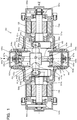
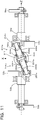
- Fig. 1 is a configuration diagram illustrating the schematic configuration of a displacement machine (positive displacement machine) 20 according to a first embodiment of the present disclosure.
- the displacement machine 20 of the first embodiment is configured as a compressor to boost the pressure of a gas that serves as a working fluid.
- the displacement machine 20 of the first embodiment includes a pair of cylindrical guide members 30a and 30b having a center axis in a vertical direction in the drawing (in a Y axis direction); a reciprocating member 40 provided with a pair of pistons 42a and 42b that are guided by these cylindrical guide members 30a and 30b to reciprocate in the vertical direction in the drawing (in the Y axis direction) and to swing about the common center axis of the cylindrical guide members 30a and 30b (about a Y axis); a pair of shaft members 50a and 50b placed in the middle of the cylindrical guide members 30a and 30b and arranged to have rotation axes that are straight lines (a Z axis) perpendicular to the center axis of the cylindrical guide members 30a and 30b; a pair of working chambers 62a and 62b having volumes changed accompanied with a reciprocating motion of the pistons 42a and 42b; a pair of high pressure chambers 66a and 66b placed adjacent to the working chambers
- the reciprocating member 40 includes a mounting portion 41 formed in the center thereof such that a pair of first arm portions 44a and 44b are mounted to the mounting portion 41.
- Fig. 2 is an enlarged view illustrating a part where the pair of first arm portions 44a and 44b are mounted to the mounting portion 41.
- the mounting portion 41 has a through hole 41a that is formed perpendicularly to the common center axis of the cylindrical guide members 30a and 30b (the Y axis).
- the through hole 41a is formed to have a diameter slightly larger than the diameters of the pair of first arm portions 44a and 44b.
- the pair of first arm portions 44a and 44b formed in a cylindrical shape are inserted into this through hole 41a across slight clearances.
- the mounting portion 41 and the pair of first arm portions 44a and 44b are mounted by a pin member 46, which is inserted at an intersection between the common center axis of the cylindrical guide members 30a and 30b (the Y axis) and a center axis of the pair of first arm portions 44a and 44b in a direction perpendicular to both the center axes, such as to be slidable in an axial direction of the pin member 46 and to be rotatable about an axis of the pin member 46.
- Outer circumference spherical portions 45a and 45b having spherical centers P1a and P1b on the arm axes are formed at or are mounted and fixed to respective ends of the first arm portions 44a and 44b.
- the pistons 42a and 42b have fluid flow paths 63a and 63b that are formed to supply a working fluid to the working chambers 62a and 62b.
- Inlet valves 64a and 64b are mounted to the fluid flow paths 63a and 63b, such as to be opened when the pressures in the working chambers 62a and 62b become lower than the pressure in a working fluid space 60 provided between the pistons 42a and 42b.
- Discharge valves 67a and 67b are mounted to the partition walls 65a and 65b provided between the working chambers 62a and 62b and the high pressure chambers 66a and 66b, such as to be opened when the pressures in the working chambers 62a and 62b become higher than the pressures in the high pressure chambers 66a and 66b.
- Outlet pipes 68a and 68b are mounted to the high pressure chambers 66a and 66b.
- a non-illustrated inlet pipe is mounted to the case 22 such as to communicate with the working fluid space 60.
- the working fluid flows from the inlet pipe into the working fluid space 60, is supplied through the fluid flow paths 63a and 63b and the inlet valves 64a and 64b to the working chambers 62a and 62b by the reciprocating motion of the pistons 42a and 42b, flows through the discharge valves 67a and 67b into the high pressure chambers 66a and 66b, and flows out from the outlet pipes 68a and 68b.
- the shaft members 50a and 50b are supported to be rotatable by ball bearings 51a, 51b, 52a and 52b.
- a pair of second arm portions 54a and 54b are mounted to respective one ends (reciprocating member 40-side ends) of the shaft members 50a and 50b at positions displaced from the rotation axes of the shaft members 50a and 50b, such as to support the first arm portions 44a and 44b of the reciprocating member 40.
- These second arm portions 54a and 54b are formed as inner circumference cylindrical members having a center axis that is an axis parallel to the rotation axes of the shaft members 50a and 50b, and are configured to place the outer circumference spherical portions 45a and 45b of the first arm portions 44a and 44b slidably in the inner circumference cylinders thereof.
- Driving the shaft members 50a and 50b to rotate reversely relative to each other causes the second arm portions 54a and 54b to rotate reversely relative to each other.
- the reciprocating member 40 has a reciprocating motion of an amplitude 2 ⁇ having a top dead center shown in Fig. 18(b) and a bottom dead center shown in Fig. 18(d) , along with a counterclockwise swinging motion of a swing half amplitude angle ⁇ max shown in Figs.
- a pair of main weight balances 58a and 58b are mounted to respective one ends of the shaft members 50a and 50b such that the direction of centrifugal force thereof is a direction opposite to the direction of centrifugal force of the second arm portions 54a and 54b.
- a pair of sub weight balances 59a and 59b are mounted to the respective other ends (ends on the sides opposite to the reciprocating member 40) of the shaft members 50a and 50b such that the direction of centrifugal force thereof is a direction opposite to the direction of centrifugal force of the main weight balances 58a and 58b.
- the displacement machine 20 of the first embodiment having the above configuration can reduce generation of excitation forces other than the torque about the Y axis to zero, out of the inertial forces in the directions of three axes (X axis, Y axis and Z axis) in the Cartesian Coordinates System and torques about the three axes generated by the inertial forces.
- the pair of first arm portions 44a and 44b are inclined by a small angle to a perpendicular angle (90 degrees) that is perpendicular to the center axis of the reciprocating member 40 as shown by broken lines in Fig. 2 .
- the through hole 41a of the mounting portion 41 is, however, formed in the reciprocating member 40 to have the diameter slightly larger than the diameters of the pair of first arm portions 44a and 44b.
- This configuration provides small spaces between the through hole 41a and the pair of first arm portions 44a and 44b and thereby allows the pair of first arm portions 44a and 44b to be inclined by a small angle to the perpendicular angle (90 degrees). Accordingly, even when there is a slight misalignment between the second arm portions 54a and 54b in the Y-axis direction shown in Fig.
- this configuration suppresses the reciprocating member 40 from being inclined to the common center axis of the cylindrical guide members 30a and 30b.
- the through hole 41a of the mounting portion 41 is, however, formed in the reciprocating member 40 to have the diameter slightly larger than the diameters of the pair of first arm portions 44a and 44b, and the pin member 46 is mounted to be slidable in the axial direction.
- This configuration allows the pair of first arm portions 44a and 44b to slightly move in the perpendicular direction. Accordingly, even when there is a slight difference between the absolute values of the positions of the second arm portions 54a and 54b in the X axis direction shown in Fig.
- this configuration suppresses the reciprocating member 40 from moving in parallel and being deviated from the common center axis of the cylindrical guide members 30a and 30b.
- the deviation from the normal positional relationship between the second arm portions 54a and 54b described above is caused by a misalignment in the Y axis direction simultaneously with a misalignment in the X axis direction shown in Fig. 1 .
- the combination of the operation against the misalignment in the Y axis direction described above with the operation against the misalignment in the X axis direction described above can deal with the deviation.
- the reciprocating member 40 is accordingly neither inclined to nor deviated from the common center axis of the cylindrical guide members 30a and 30b.
- the diameter of the through hole 41a is designed to such a dimension that enables the slight amount of inclination and the slight amount of parallel translation of the first arm portions 44a and 44b to be sufficiently absorbed.
- the reciprocating member 40 has the mounting portion 41 that is formed in the center thereof and that is provided with the through hole 41a formed to have the diameter slightly larger than the diameters of the pair of first arm portions 44a and 44b.
- the first arm portions 44a and 44b are inserted into the through hole 41a across the slight clearances.
- the mounting portion 41 and the pair of first arm portions 44a and 44b are mounted by the pin member 46 having the axis that is perpendicular to both the center axis of the reciprocating member 40 and the center axis of the pair of first arm portions 44a and 44b at the intersection between these center axes, such as to be slidable in the axial direction of the pin member 46 and to be rotatable about the axis of the pin member 46.
- this configuration suppresses the reciprocating member 40 from being inclined to or deviated from the common center axis of the cylindrical guide members 30a and 30b.
- this configuration avoids a potential trouble (an increase in frictional resistance or inoperative) caused by the inclination or the deviation of the reciprocating member 40 to or from the common center axis of the cylindrical guide members 30a and 30b.
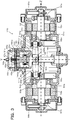
- Fig. 3 is a configuration diagram illustrating the schematic configuration of the displacement machine 120 according to the second embodiment of the present disclosure.
- the displacement machine 120 of the second embodiment is configured as a compressor to boost the pressure of a gas that serves as a working fluid.
- the displacement machine 120 of the second embodiment has a configuration similar to the configuration of the displacement machine 20 of the first embodiment, except a different mounting structure of a pair of arm members 144a and 144b and omission of the cylindrical guide member 30b, the piston 42b, the working chamber 62b, the fluid flow path 63b, the inlet valve 64b, the partition wall 65b, the high pressure chamber 66b, the discharge valve 67 and the outlet pipe 68b that are provided in the displacement machine 20 of the first embodiment and that are placed in the lower part of Fig. 1 .
- like components of the displacement machine 120 of the second embodiment to the components of the displacement machine 20 of the first embodiment are expressed by like reference signs, and their description is omitted.
- the following mainly describes the mounting structure of the pair of arm members 144a and 144b in the displacement machine 120 of the second embodiment.
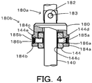
- Fig. 4 is a diagram illustrating a mounting structure part of the pair of arm members 144a and 144b in an XY plane shown in Fig. 3 .
- the displacement machine 120 of the second embodiment has a mounting member 180 including: a first mounting portion 180a configured to cause a reciprocating member 140 to pass therethrough and mounted to the reciprocating member 140; and a second mounting portion 180b configured to cause an arm mounting portion for the pair of arm members 144a and 144b to be mounted thereto.
- the first mounting portion 180a of the mounting member 180 has a pair of through holes 182 that are formed to be parallel to a center axis of the pair of arm members 144a and 144b.
- the reciprocating member 140 has a through hole 140a that is formed to be aligned with the pair of through holes 182.
- the mounting member 180 or more specifically the first mounting portion 180a thereof is mounted to the reciprocating member 140 by a pin member 183 inserted in the pair of through holes 182 and the through hole 140a of the reciprocating member 140 such as to be rotatable about an axis of the pin member 183. This configuration causes the mounting member 180 to be swung about the axis of the pin member 183.
- the second mounting portion 180b of the mounting member 180 is provided with a pair of mounting arm portions 184a and 184b that are formed to be extended downward in Fig. 4 .
- the pair of mounting arm portions 184a and 184b are provided with a pair of through holes 185a and 185b that are formed to be skew to the pin member 183 and to be extended in a direction perpendicular to the pin member 183.
- the arm mounting portion 144 for the pair of arm members 144a and 144b is, on the other hand, formed in an approximately rectangular sectional shape and has a through hole 144c formed to cause the reciprocating member 140 to pass therethrough and a pair of through holes 144d and 144e formed to be aligned with the pair of through holes 185a and 185b.
- the pair of mounting arm portions 184a and 184b are arranged to hold the arm mounting portion 144 therebetween, such that the pair of through holes 185a and 185b formed in the pair of mounting arm portions 184a and 184b are aligned with the pair of through holes 144d and 144e formed in the arm mounting portion 144.
- Pin members 186a and 186b are respectively inserted into the pair of through holes 185a and 185b and the pair of through holes 144d and 144e.
- the pair of arm members 144a and 144b are mounted to the second mounting portion 180b of the mounting member 180, such as to be rotatable about respective axes of the pin members 186a and 186b and to keep slight clearances from bottoms 184c of the pair of mounting arm portions 184a and 184b.
- This configuration enables the pair of arm members 144a and 144b to be slightly rotated about the respective axes of the pair of pin members 186a and 186b.
- the pair of first arm portions 144a and 141a are inclined by a small angle to an angle (90 degrees) perpendicular to a center axis of the reciprocating member 140, due to the misalignment between the rotation axis of the shaft member 50a and the rotation axis of the shaft member 50b.
- the pair of arm members 144a and 144b are, however, mounted to the second mounting portion 180b, such as to be rotatable about the respective axes of the pin members 186a and 186b and to keep the slight clearances from the bottoms 184c of the pair of mounting arm portions 184a and 184b.
- This configuration enables the pair of arm members 144a and 144b to be slightly rotated about the respective axes of the pair of pin members 186a and 186b. Accordingly, even when the pair of first arm portions 144a and 144b are slightly inclined due to, for example, the slight misalignment between the rotation axis of the shaft member 50a and the rotation axis of the shaft member 50b in the Y axis direction shown in Fig. 3 , this configuration suppresses the reciprocating member 140 from being inclined to the center axis of the cylindrical guide member 30a.
- the mounting member 180 or more specifically the first mounting portion 180a thereof is, however, mounted to the reciprocating member 140 by the pin member 183 inserted in the pair of through holes 182 and the through hole 140a of the reciprocating member 140 such as to be rotatable about the axis of the pin member 183.
- This configuration causes the pair of first arm portions 144a and 141a to be swung about the axis of the pin member 183.
- a small extent of such swinging motion may be regarded as parallel translation of the pair of first arm portions 144a and 141a in an axial direction of the pin members 186a and 186b. This accordingly allows the pair of first arm portions 144a and 141a to slightly move in the direction perpendicular to the center axis of the reciprocating member 140.
- this configuration suppresses the reciprocating member 140 from being deviated from the center axis of the cylindrical guide member 30a.
- the deviation from the normal positional relationship between the second arm portions 54a and 54b described above is caused by a misalignment in the Y axis direction simultaneously with a misalignment in the X axis direction shown in Fig. 3 .
- the combination of the operation against the misalignment in the Y axis direction described above with the operation against the misalignment in the X axis direction described above can deal with the deviation.
- the reciprocating member 140 is accordingly neither inclined to nor deviated from the center axis of the cylindrical guide member 30a.
- the clearance between the arm mounting portion 144 and the bottoms 184c of the pair of mounting arm portions 184a and 184b and the clearance between the reciprocating member 140 and the through hole 144c are designed to such dimensions that enable the slight amount of inclination and the slight amount of parallel translation of the first arm portions 144a and 144b to be sufficiently absorbed.
- the mounting member 180 or more specifically the first mounting portion 180a thereof is mounted to the reciprocating member 140 by the pin member 183 inserted in the pair of through holes 182 and the through hole 140a of the reciprocating member 140 such as to be rotatable about the axis of the pin member 183.
- the pair of arm members 144a and 144b are mounted to the second mounting portion 180b, such as to be rotatable about the respective axes of the pin members 186a and 186b and to keep the slight clearances from the bottoms 184c of the pair of mounting arm portions 184a and 184b.
- this configuration suppresses the reciprocating member 140 from being inclined to or deviated from the center axis of the cylindrical guide member 30a.
- this configuration avoids a potential trouble (an increase in frictional resistance or inoperative) caused by the inclination or the deviation of the reciprocating member 140 to or from the center axis of the cylindrical guide member 30a.
- the following describes a displacement machine 220 according to a third embodiment of the present disclosure.
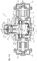
- Fig. 5 is a configuration diagram illustrating the schematic configuration of the displacement machine 220 according to the third embodiment of the present disclosure.
- the displacement machine 220 of the third embodiment is configured as a compressor to boost the pressure of a gas that serves as a working fluid.
- the displacement machine 220 of the third embodiment has a configuration similar to the configuration of the displacement machine 20 of the first embodiment, except a different mounting structure of a pair of arm members 244a and 244b and a different mounting structure of the pair of arm members 244a and 244b to a pair of second arm portions 254a and 254b.
- the pair of arm members 244a and 244b respectively have a pair of shaft members 280a and 280b and a pair of revolving members 290a and 290b.
- the pair of shaft members 280a and 280b are inserted into an inner circumference cylindrical surface 241a of a mounting portion 241.
- the pair of arm members 244a and 244b are mounted to the mounting portion 241 in a center thereof by a pin member 246 having an axis in a direction perpendicular to a center axis of a reciprocating member 240 and to a center axis of the pair of shaft members 280a and 280b, such as to be slidable in an axial direction of the pin member 246 and to be rotatable about the axis of the pin member 246.
- Fig. 6 is an enlarged view illustrating a part including the arm member 244a shown in Fig. 5 .
- FIG. 7 is an exploded perspective view illustrating the pair of revolving members 290a and 290b and components used for the mounting structure to the pair of second arm portions 254a and 254b.
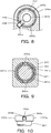
- Fig. 8 is a sectional view illustrating a section in an A-A plane shown in Fig. 6 .
- the pair of shaft members 280a and 280b are formed in a columnar shape having a small-diameter leading end and are inserted into the revolving members 290a and 290b formed in a hollow cylindrical shape such as to be slidable in an axial direction of the revolving members 290a and 290b and to be rotatable about an axis of the revolving members 290a and 290b.
- the revolving member 290a or 290b has a tubular portion 291 in a hollow cylindrical shape and an outer circumference spherical portion 292 formed at an end of the tubular portion 291.
- a pair of convexes 293a and 293b are formed at positions away from each other at an interval of 180 degrees on the outer side of the tubular portion 291 at an opposite end that is opposite to an end where the outer circumference spherical portion 292 is formed.
- the outer circumference spherical portion 292 is held to be slidable by a pair of inner circumference spherical members 295a and 295b that are split in a plane parallel to an axial direction of the tubular portion 291.
- a through hole 295c is formed in the inner circumference spherical member 295b, and a pin member 296 is fit in this through hole 295c. As shown in Fig.
- the pin member 296 is protruded from the inner circumference spherical member 295b to be engaged with a groove of the second arm portion 254a, so that the inner circumference spherical members 295a and 295b are mounted to the second arm portion 254a to be not rotatable.
- the inner circumference spherical members 295a and 295b are held between a step and a retaining ring and are thereby mounted to the second arm portion 254a such as to be not slidable in the axial direction.
- this configuration causes the pair of revolving members 290a and 290b to revolve about the rotation axes of the pair of shaft members 50a and 50b accompanied with rotation of the pair of shaft members 50a and 50b and to have one rotating motion relative to one revolving motion.
- the outer circumference spherical portion 292 has a groove 292a that is formed in the axial direction along an outer circumferential surface thereof, and a slider 294 is fit in the groove 292a to slide along the groove 292a.
- the slider 294 has a through hole 294a formed in a center thereof.
- a small-diameter pin portion at a leading end of the pin member 296 is fit in this through hole 294a, so that the pin member 296 is fixed to be not movable relative to the inner circumference spherical member 295b.
- This configuration allows the revolving members 290a and 290b to have a rotating motion in a direction of the groove 292a relative to the pair of inner circumference spherical members 295a and 295b by means of the groove 292a and the slider 294 and a rotating motion about a center axis of the pin member 296.
- Fig. 9 is a sectional view illustrating a section in a B-B plane shown in Fig. 6 .
- Fig. 10 is a partial configuration diagram illustrating the schematic configuration of a part involved in mounting the pair of convexes 293a and 293b formed in the tubular portion 291 to the mounting portion 241. As illustrated, the pair of convexes 293a and 293b formed at the end of the tubular portion 291 of the revolving member 290a or 290b are held between a pair of semiring members 297a and 297b and are mounted to the mounting portion 241 to be rotatable about an axis thereof.
- the pair of semiring members 297a and 297b are formed to have diameters on an inner circumference side that are slightly larger than a diameter of the tubular portion 291.
- the pair of semiring members 297a and 297b have recesses 298a and 298b formed in contact regions with the pair of convexes 293a and 293b, and the pair of convexes 293a and 293b are fit in the recesses 298a and 298b.
- This configuration allows the revolving members 290a and 290b to slightly move in a direction passing through the pair of convexes 293a and 293b (a vertical direction in Fig. 9 ) but not to move in any different directions.
- the revolving members 290a and 290b are mounted such that the pair of convexes 293a and 293b face in a direction of the center axis of the reciprocating member 240 (a Y axis direction in Fig. 5 ) when the reciprocating member 240 is located at a top dead center and a bottom dead center, as shown in Fig. 5 .
- the pair of convexes 293a and 293b face in a direction perpendicular to the center axis of the reciprocating member 240. Accordingly, when the reciprocating member 240 is located at the top dead center and the bottom dead center, the pair of arm members 244a and 244b are allowed to slightly move in the direction of the center axis of the reciprocating member 240 (the Y axis direction in Fig. 5 ).
- the pair of arm members 244a and 244b are mounted in the center by the pin member 246 to be rotatable about the X axis.
- One of the pair of arm members 244a and 244b slightly moves in one direction out of the direction of the center axis of the reciprocating member 240 (for example, an upward direction in Fig. 5 ), whereas the other of the pair of arm members 244a and 244b slightly moves in the other direction out of the direction of the center axis of the reciprocating member 240 (for example, a downward direction in Fig. 5 ).
- the pair of arm members 244a and 244b are slightly rotatable about the axis of the pin member 246.
- the pair of first arm portions 244a and 244a are inclined by a small angle to a perpendicular angle (90 degrees) that is perpendicular to the center axis of the reciprocating member 240, due to the misalignment between the rotation axis of the shaft member 50a and the rotation axis of the shaft member 50b, as described above with reference to Fig. 2 .
- the pair of arm members 244a and 244b are, however, slightly rotatable about the axis of the pin member 246.
- This configuration allows the pair of first arm portions 244a and 244a to be inclined by a small angle to the perpendicular angle (90 degrees). Accordingly, even when there is a slight misalignment between the rotation axis of the shaft member 50a and the rotation axis of the shaft member 50b in the Y axis direction shown in Fig. 5 , this configuration suppresses the reciprocating member 240 from being inclined to the common center axis of the cylindrical guide members 30a and 30b.
- Fig. 11 is a diagram illustrating members around the pair of first arm portions 244a and 244b in an XZ plane when the reciprocating member 240 is located at the points having the phase different by 90 degrees from the top dead center and from the bottom dead center.
- the pair of convexes 293a and 293b face in the direction perpendicular to the center axis of the reciprocating member 240 (direction parallel to the ZX plane). This configuration allows the pair of arm members 244a and 244b to slightly move in parallel in the direction passing through the pair of convexes 293a and 293b.
- the pair of arm members 244a and 244b face in a direction having a certain angle to a Z axis in the ZX plane.
- the revolving members 290a and 290b are mounted to the pair of shaft members 280a and 280b to be slidable in the axial direction and to be rotatable about the axis. This configuration allows the pair of arm members 244a and 244b to slightly move in parallel in an X axis direction in the ZX plane.
- the pair of arm members 244a and 244b are allowed to slightly move in parallel in the X axis direction in the ZX plane.
- This configuration thus allows for such parallel motion. Accordingly, even when there is a slight misalignment between the rotation axis of the shaft member 50a and the rotation axis of the shaft member 50b in the X axis direction shown in Fig. 5 , this configuration suppresses the reciprocating member 240 from moving in parallel and being deviated from the center axis of the cylindrical guide members 30a and 30b.
- the pair of arm members 244a and 244b are allowed to slightly rotate about the axis of the pin member 246.
- the pair of arm members 244a and 244b are allowed to slightly move in parallel in the X axis direction in the ZX plane.
- this configuration suppresses the reciprocating member 240 from being inclined to or deviated from the common center axis of the cylindrical guide members 30a and 30b.
- this configuration avoids a potential trouble (an increase in frictional resistance or inoperative) caused by the inclination or the deviation of the reciprocating member 40 to or from the common center axis of the cylindrical guide members 30a and 30b.
- the pair of convexes 293a and 293b of the pair of revolving members 290a and 290b face in the same direction as the center axis of the reciprocating member 240.
- This configuration restricts the motion of the pair of first arm portions 244a and 244b relative to the reciprocating member 240 in the axial direction of the pin member 246.
- the pair of convexes 293a and 293b of the pair of revolving members 290a and 290b face in the direction perpendicular to the center axis of the reciprocating member 240.
- This configuration restricts the rotations of the pair of first arm portions 244a and 244b about the axis of the pin member 246. Accordingly, whether the reciprocating member 240 is located at the top dead center and the bottom dead center or is located at the points having the phase different by 90 degrees from the top dead center and from the bottom dead center, this configuration restricts the rotating motion of the pair of shaft members 50a and 50b in an identical direction.
- the structure of mounting the pair of revolving members 290a and 290b to the pair of second arm portions 254a and 254b such as to both revolve and rotate and of holding the pair of convexes 293a and 293b between the pair of semiring members 297a and 297b and mounting the pair of convexes 293a and 293b to the mounting portion 241 such as to face in the direction of the center axis of the reciprocating member 240 when the reciprocating member 240 is located at the top dead center and the bottom dead center serves as a mechanism of restricting the rotating motion of the pair of shaft members 50a and 50b in the identical direction, in other words, a mechanism of reversely rotating the pair of shaft members 50a and 50b in synchronism with each other.
- the pair of revolving members 290a and 290b are mounted to the mounting portion 241 such that the pair of convexes 293a and 293b held between the pair of semiring members 297a and 297b face in the axial direction of the reciprocating member 240 when the reciprocating member 240 is located at the top dead center and the bottom dead center.
- the requirement is, however, that the reciprocating member 240 is allowed to slightly move in the axial direction of the reciprocating member 240 but has difficulty in moving in the other directions when the reciprocating member 240 is located at the top dead center and the bottom dead center. Any mechanism that fulfills this requirement may be employed.
- one modification may not use the semiring members 297a and 297b but may be configured to use revolving members including mounting regions that have outer circumferences formed in an elliptical sectional shape and that are to be mounted to the mounting portion 241, and to mount the revolving members such that minor radii of the mounting regions of the revolving members face in the axial direction of the reciprocating member 240 when the reciprocating member 240 is located at the top dead center and the bottom dead center.
- Another modification may be configured to use revolving members including mounting regions that are formed to have an outer circumference diameter smaller than the inner diameter of the inner circumference cylindrical surface 241a of the mounting portion 241 and that are to be mounted to the mounting portion 241, and to cause the outer circumferences of the mounting regions of the revolving members to be eccentric in a direction perpendicular to the axial direction of the reciprocating member 240 and to be close to the inner circumference cylindrical surface 241a when the reciprocating member 240 is located at the top dead center and the bottom dead center.
- Fig. 12 is a configuration diagram illustrating the schematic configuration of a displacement machine 320 as a modification of the displacement machine 120 of the second embodiment and the displacement machine 220 of the third embodiment.
- the displacement machine 320 of the modification is configured by combining the mounting structure of the first mounting portion 180a in the displacement machine 120 of the second embodiment with the mounting structure of the pair of arm members 244a and 244b in the displacement machine 220 of the third embodiment.
- like components of the displacement machine 320 of the modification to the components of the displacement machine 120 of the second embodiment or the components of the displacement machine 220 of the third embodiment are expressed by like reference signs, and their description is omitted.
- a reciprocating member 340 is formed in an approximately cylindrical shape and is arranged to slide in the cylindrical guide member 30a.
- the reciprocating member 340 has through holes 340a and 340b that are formed in a direction perpendicular to a center axis of the reciprocating member 340.
- a mounting member 341 has a through hole 341a that is formed to be aligned with the through holes 340a and 340b.
- the mounting member 341 is mounted to the reciprocating member 340 to be rotatable by inserting a pin member 383 into the through holes 340a and 340b of the reciprocating member 340 aligned with the through hole 341a.
- the mounting structure of this mounting member 341 to the reciprocating member 340 corresponds to the mounting structure of the first mounting portion 180a in the displacement machine 120 of the second embodiment.
- a pair of first arm portions 244a and 244b have a pair of shaft members 280a and 280b and a pair of revolving members 290a and 290b, which are both rotatable, like the third embodiment.
- the pair of revolving members 290a and 290b are respectively held between steps and retaining rings of the shaft members 280a and 280b. This configuration restricts a sliding motion of the pair of revolving members 290a and 290b in an axial direction.
- the pair of shaft members 280a and 280b are mounted to the mounting member 341 by a pin member 246 having an axis in a direction perpendicular to a center axis of the reciprocating member 340 and a center axis of the pair of shaft members 280a and 280b, such as to be rotatable about the axis of the pin member 246.
- the pair of revolving members 290a and 290b are mounted to a pair of second arm portions 254a and 254b such as to be not rotatable by engagement of pin members 296 with grooves of the second arm portions 254a and 254b in the state that an outer circumference spherical portion 292 formed on one end of each of the revolving members 290a and 290b is held by a pair of inner circumference spherical members 295a and 295b to be slidable.
- This modification does not restrict a motion of the inner circumference spherical members 295a and 295b in an axial direction relative to the second arm portions 254a and 254b.
- the pair of revolving members 290a and 290b are mounted to inner circumference cylindrical surfaces 340c and 340d formed in the reciprocating member 340 in the state that a pair of convexes 293a and 293b formed on the other end of each of the revolving members 290a and 290b are held by and between a pair of semiring members 297a and 297b.
- the mounting structure of the pair of shaft members 280a and 280b to the mounting member 341, the mounting structure of the pair of revolving members 290a and 290b to the pair of second arm portions 254a and 254b and the mounting structure of the pair of revolving members 290a and 290b to the reciprocating member 340 correspond to the mounting structure of the pair of arm members 244a and 244b in the displacement machine 220 of the third embodiment.
- the displacement machine 320 of this modification has the mounting structure corresponding to the mounting structure of the first mounting portion 180a in the displacement machine 120 of the second embodiment and the mounting structure corresponding to the mounting structure of the pair of arm members 244a and 244b in the displacement machine 220 of the third embodiment as described above. Accordingly, the displacement machine 320 of the modification has advantageous effects similar to the advantage effects achieved by the mounting structure of the first mounting portion 180a in the displacement machine 120 of the second embodiment and the advantageous effects achieved by the mounting structure of the pair of arm members 244a and 244b in the displacement machine 220 of the third embodiment.
- the displacement machine 320 of the modification has the advantageous effects of suppressing the reciprocating member 340 from being inclined to or deviated from the center axis of the cylindrical guide member 30a and avoiding a potential trouble (an increase in frictional resistance or inoperative) caused by the inclination or the deviation of the reciprocating member 340 to or from the center axis of the cylindrical guide member 30a, even in the event of a misalignment between the rotation axis of the shaft member 50a and the rotation axis of the shaft member 50b or a difference between the displacements of second arm portions, as well as the advantageous effects of suppressing the occurrence of backlash.
- Fig. 13 is a configuration diagram illustrating the schematic configuration of the displacement machine 420 according to the fourth embodiment of the present disclosure.
- the displacement machine 420 of the fourth embodiment is configured as a compressor to boost the pressure of a gas that serves as a working fluid.
- like components of the displacement machine 420 of the fourth embodiment to the components of the displacement machine 20 of the first embodiment are expressed by like reference signs, and their description is omitted.
- FIG. 14 is a diagram illustrating members around a pair of first arm portions 444a and 444b and a pair of second arm portions 454a and 454b in an XZ plane when a reciprocating member 440 is located at points having a phase different by 90 degrees from a top dead center and from a bottom dead center.
- the reciprocating member 440 is formed in an approximately cylindrical shape and is arranged to slide in a cylindrical guide member 30a.
- the reciprocating member 440 is mounted to a mounting member 441 such as to be rotatable by insertion of a pin member 483 into through holes 440a and 440b formed in the reciprocating member 440 and a through hole 441a formed in the mounting member 441. This configuration enables the mounting member 441 to swing about an axis of the pin member 483.
- the pair of first arm portions 444a and 444b include a pair of shaft members 480a and 480b and a pair of revolving members 490a and 490b.
- the pair of shaft members 480a and 480b are mounted to the mounting member 441 by a pin member 446 having an axis in a direction perpendicular to a center axis of the reciprocating member 440 and a center axis of the pair of shaft members 480a and 480b, such as to be slidable in an axial direction of the pin member 446 and to be rotatable about an axis of the pin member 446.
- This configuration enables the pair of first arm portions 444a and 444b to move in the axial direction of the pin member 446 and to rotate about the axis of the pin member 446.
- a pair of inner circumference spherical members are mounted to second arm portions 454a and 454b to be slidable in an axial direction of the second arm portions 454a and 454b in the state that outer circumference spherical portions formed at respective one ends of the pair of revolving members 490a and 490b in the pair of first arm portions 444a and 444b are held to be slidable by the inner circumference spherical members.
- a pair of convexes are, however, not formed at respective other ends of the pair of revolving members 490a and 490b in the pair of first arm portions 444a and 444b. These other ends are not mounted to the reciprocating member 440 or to the mounting member 441.
- these mechanisms cause the displacement machine 420 of the fourth embodiment to suppress the reciprocating member 440 from being inclined to or deviated from the center axis of the cylindrical guide member 30a and to avoid a potential trouble (an increase in frictional resistance or inoperative) caused by the inclination or the deviation of the reciprocating member 440 to or from the center axis of the cylindrical guide member 30a, even in the event of a misalignment between the rotation axis of the shaft member 50a and the rotation axis of the shaft member 50b or a difference between the displacements of second arm portions.
- a pair of first bevel gears 472a and 472b that are coaxial with the center axis of the pair of shaft members 50a and 50b are mounted to the pair of second arm portions 454a and 454b and a pair of main weight balances 58a and 58b, which are mounted to the pair of shaft members 50a and 50b, by a plurality of bolts 473a and 473b.
- the pair of first bevel gears 472a and 472b engage with a second bevel gear 474 that is axially supported by a ball bearing 476 mounted to a bottom face of a case 22 by a bolt 477.
- first bevel gear 472a and the first bevel gear 472b synchronously rotate in opposite directions.
- a gear mechanism configured by the pair of first bevel gears 472a and 472b and the second bevel gear 474 serves as a mechanism of synchronously reversing the pair of shaft members 50a and 50b.
- This configuration suppresses the occurrence of backlash due to the swinging motion of the mounting member 441 and the rotating motion of the pair of first arm portions 444a and 444b about the axis of the pin member 446.
- no motor is mounted to the shaft member 50b, whereas a motor 70a is mounted to the shaft member 50a.
- the gear mechanism configured by the pair of first bevel gears 472a and 472b and the second bevel gear 474 serves to transmit the power of the motor 70a to the shaft member 50b as a power of rotation in the opposite direction. It is accordingly not necessary to mount a motor to the shaft member 50b.
- the mounting member 441 is mounted to the reciprocating member 440 such as to be swingable about the axis of the pin member 483.
- the pair of first arm portions 444a and 444b are mounted to the mounting member 441 such as to be rotatable about the axis of the pin member 446.
- This configuration suppresses the reciprocating member 440 from being inclined to or deviated from the center axis of the cylindrical guide member 30a and avoids a potential trouble (an increase in frictional resistance or inoperative) caused by the inclination or the deviation of the reciprocating member 440 to or from the center axis of the cylindrical guide member 30a, even in the event of a misalignment between the rotation axis of the shaft member 50a and the rotation axis of the shaft member 50b or a difference between the displacements of second arm portions.
- the pair of first bevel gears 472a and 472b and the second bevel gear 474 are provided to configure the gear mechanism of synchronously reversing the pair of shaft members 50a and 50b.
- the gear mechanism configured by the pair of first bevel gears 472a and 472b and the second bevel gear 474 serves to transmit the power of the motor 70a to the shaft member 50b as a power of rotation in the opposite direction. It is accordingly not necessary to mount a motor to the shaft member 50b.
- the second bevel gear 474 provided to engage with the pair of first bevel gears 472a and 472b is axially supported by the ball bearing 476 mounted to the bottom face of the case 22.
- a pair of second bevel gears 474a and 474b may be provided to be opposed to and engage with a pair of first bevel gears 472a and 472b.
- Fig. 15 is a configuration diagram illustrating the schematic configuration of the displacement machine 520 of the modification.
- FIG. 16 is a diagram illustrating members around a pair of first arm portions 444a and 444b and a pair of second arm portions 454a and 454b in an XZ plane when a reciprocating member 440 is located at points having a phase different by 90 degrees from a top dead center and from a bottom dead center in the displacement machine 520 of the modification.
- the pair of second bevel gears 474a and 474b are arranged to have a rotation axis (in an X axis direction in Fig. 16 ) that is an axis perpendicular to a center axis of the reciprocating member 440 and a center axis of a pair of shaft members 50a and 50b.
- the pair of second bevel gears 474a and 474b are fixed to inner rings of ball bearings 476a and 476b by nuts 477a and 477b and are axially supported via the ball bearings 476a and 476b by a fixation member 479 mounted to a case 22 to engage with the pair of first bevel gears 472a and 472b.
- the gear mechanism configured by the pair of first bevel gears 472a and 472b and the second bevel gears 474a and 474b serves as a mechanism of synchronously reversing the pair of shaft members 50a and 50b. This configuration accordingly suppresses the occurrence of backlash caused by the swinging motion of the mounting member 441 and the rotating motion of the pair of first arm portions 444a and 444b about the axis of the pin member 446.
- the present disclosure is applicable to the manufacturing industry of displacement machine and the like.
Landscapes
- Engineering & Computer Science (AREA)
- Mechanical Engineering (AREA)
- General Engineering & Computer Science (AREA)
- Compressors, Vaccum Pumps And Other Relevant Systems (AREA)
- Compressor (AREA)
Abstract
Description
- The present disclosure relates to a displacement machine and more specifically relates to a low-vibration displacement machine configured such that a piston has a swinging motion along with a reciprocating motion.
- A proposed displacement machine(positive displacement machine) includes a reciprocating member provided with two pistons guided by a cylindrical guide member and with a pair of first arm portions arranged symmetrically from a center of these two pistons in a direction perpendicular to a center axis of the cylindrical guide member; a pair of shaft members arranged symmetrically such as to be perpendicular to the center axis of the cylindrical guide member; a pair of second arm portions mounted to the respective shaft members at positions displaced from rotation axes of the respective shaft members to hold the respective first arm portions; and a pair of working chambers configured to have changes in volume by reciprocating motion of the two pistons, and is configured to cause the reciprocating member to have a reciprocating motion along with a swinging motion (as described in, for example, Patent Literature 1).
Fig. 17 is a configuration diagram illustrating the schematic configuration of adisplacement machine 920 of a prior art. For the purpose of comparison with adisplacement machine 20 according to a first embodiment of the present disclosure described later, thedisplacement machine 920 of the prior art has a similar configuration. - The displacement machine (positive displacement machine) 920 of the prior art is configured as a compressor to boost the pressure of a gas that serves as a working fluid. As illustrated, the
displacement machine 920 includes a pair of cylindrical guide members 930a and 930b having a center axis in a vertical direction in the drawing (in a Y axis direction); a reciprocatingmember 940 provided with a pair ofpistons cylindrical guide members shaft members working chambers pistons high pressure chambers 966a and 966b placed adjacent to theworking chambers partition walls motors shaft members case 922 configured to place these components therein. - The reciprocating
member 940 has amounting portion 941 that is provided in the middle of the reciprocatingmember 940 and that includes a through hole 941a formed to be perpendicular to the center axis of the cylindrical guide members 930a and 930b (the Y axis). A pair offirst arm portions mounting portion 941. Themounting portion 941 and the pair offirst arm portions pin member 946, which is inserted at an intersection between the center axis of the cylindrical guide members 930a and 930b (the Y axis) and a center axis of thefirst arm portions spherical portions first arm portions - The
pistons fluid flow paths chambers Inlet valves fluid flow paths working chambers fluid space 960 provided between thepistons Discharge valves 967a and 967b are mounted to thepartition walls working chambers high pressure chambers 966a and 966b, such as to be opened when the pressures in theworking chambers high pressure chambers 966a and 966b.Outlet pipes 968a and 968b are mounted to thehigh pressure chambers 966a and 966b. Additionally, a non-illustrated inlet pipe is mounted to thecase 922 such as to communicate with the workingfluid space 960. Accordingly, the working fluid flows from the inlet pipe into theworking fluid space 960, is supplied through thefluid flow paths inlet valves working chambers pistons discharge valves 967a and 967b into thehigh pressure chambers outlet pipes 968a and 968b. - The
shaft members ball bearings second arm portions 954a and 954b are mounted to respective one ends (reciprocating member 940-side ends) of theshaft members shaft members first arm portions member 940. Thesesecond arm portions 954a and 954b are formed as inner circumference cylindrical members having a center axis that is an axis parallel to the rotation axes of theshaft members spherical portions first arm portions shaft members second arm portions 954a and 954b to rotate reversely relative to each other. This causes the outer circumferencespherical portions first arm portions shaft members member 940 to have a reciprocating motion accompanied with a swinging motion.Fig. 18 is a diagram illustrating the state of the reciprocatingmember 940 that has a reciprocating motion accompanied with a swinging motion.Fig. 19 is a diagram illustrating thereciprocating member 940 that has the reciprocating motion accompanied with the swinging motion viewed from the top inFig. 17 .Figs. 18(a) to 18(e) and Figs. 19(a) to 19(e) illustrate a variation in the state when theshaft members reciprocating member 940 is located in the center of the reciprocating motion. As illustrated, the reciprocatingmember 940 has a reciprocating motion of an amplitude 2ε having a top dead center shown inFig. 18(b) and a bottom dead center shown inFig. 18(d) , along with a counterclockwise swinging motion of a swing half amplitude angle θmax shown inFigs. 19(a) and 19(e) and a clockwise swinging motion of the swing half amplitude angle θmax shown inFig. 19(c) . InFig. 18 , the outer circumferencespherical portion 945a on the front side revolves counterclockwise, while the outer circumferencespherical portion 945b on the rear side revolves clockwise. This causes theshaft member 950a to rotate counterclockwise, while causing theshaft member 950b to rotate clockwise. - A pair of
main weight balances 958a and 958b are mounted to respective one ends of theshaft members second arm portions 954a and 954b. A pair ofsub weight balances shaft members main weight balances 958a and 958b. - The
displacement machine 920 of the prior art can reduce generation of excitation forces other than the torque about the Y axis to zero, out of the inertial forces in the directions of three axes (X axis, Y axis and Z axis) in the Cartesian Coordinates System and torques about the three axes generated by the inertial forces. - PTL1:
JP 2016-017513A - The
displacement machine 920 described above is, however, likely to have a large frictional resistance and even become inoperative, due to a slight manufacturing error. When there is a slight misalignment between the rotation axis of theshaft member 950a and the rotation axis of theshaft member 950b due to a manufacturing error, for example, when there is a misalignment in the Y axis direction shown inFig. 17 or when there is a misalignment in an X axis direction perpendicular to the Y axis and the Z axis shown inFig. 17 , this misalignment is likely to incline the center axis of the reciprocatingmember 940 or deviate the center axis of the reciprocatingmember 940 from the common center axis of the cylindrical guide members 930a and 930b. This increases the frictional resistance between thepistons displacement machine 920 to become inoperative depending on the increased degree of the frictional resistance. Such malfunction is caused by not only an error in assembling theshaft member 950a and theshaft member 950b but a manufacturing error such as displacements of the second arm portions of theshaft members - A main object of a displacement machine of the present disclosure is to smoothly operate even in the event of, for example, a misalignment between rotation axes of a pair of shaft members or a manufacturing error such as displacements of second arm portions.
- The displacement machine of the present disclosure is implemented by aspects described below, in order to achieve the main object described above.
- According to one aspect of the present disclosure, there is provided a displacement machine comprising a cylindrical guide member in a cylindrical shape; a reciprocating member provided with a piston portion that is guided by an inner circumferential surface of the cylindrical guide member to have a reciprocating motion in a center axis direction of the cylindrical guide member and a swinging motion about a center axis of the cylindrical guide member; a pair of first arm portions mounted to the reciprocating member to be perpendicular to the center axis of the cylindrical guide member and to be symmetric with respect to the center axis; a pair of shaft members arranged to be perpendicular to the center axis of the cylindrical guide member and to be symmetric with respect to the center axis; a pair of second arm portions mounted to the pair of shaft members such as to respectively support the pair of first arm portions at positions displaced from rotation axes of the pair of shaft members; and a working chamber configured to have a change in volume accompanied with the reciprocating motion of the piston portion. The pair of first arm portions and the piston portion are mounted such that an angle between a center axis of the pair of first arm portions and a center axis of the piston portion is displaceable by a predetermined small angle from 90 degrees and that the pair of first arm portions are movable in parallel by a predetermined small distance in a direction perpendicular to the center axis of the piston portion.
- In the displacement machine (positive displacement machine) of this aspect, the pair of first arm portions and the piston portion are mounted such that the angle between the center axis of the pair of first arm portions and the center axis of the piston portion is displaceable by the predetermined small angle from 90 degrees and that the pair of first arm portions are movable in parallel by the predetermined small distance in the direction perpendicular to the center axis of the piston portion.
- It is here assumed that the pair of shaft members have a slight misalignment between a rotation axis of one shaft member and a rotation axis of the other shaft member in the center axis direction of the cylindrical guide member, due to, for example, a manufacturing error or an assembling error. In this case, the pair of first arm portions are inclined by a slight angle from an angle perpendicular to the center axis of the cylindrical guide member (90 degrees), due to the misalignment between the rotation axis of one shaft member and the rotation axis of the other shaft member. In the displacement machine of this aspect, however, the pair of first arm portions and the piston portion are mounted such that the angle between the center axis of the pair of first arm portions and the center axis of the piston portion is displaceable by the predetermined small angle from 90 degrees. This configuration accordingly allows for such an inclination. Even when there is a slight misalignment between the rotation axis of one shaft member and the rotation axis of the other shaft member, this configuration suppresses the reciprocating member from being inclined to the center axis of the cylindrical guide member.
- It is also assumed that the pair of shaft members have a slight misalignment between the rotation axis of one shaft member and the rotation axis of the other shaft member in a direction that is perpendicular to the center axis of the cylindrical guide member and that is perpendicular to the rotation axes of the pair of shaft members, due to, for example, a manufacturing error or an assembling error. In this case, the pair of first arm portions slightly move in parallel in the direction perpendicular to the center axis of the cylindrical guide member, due to the misalignment between the rotation axis of one shaft member and the rotation axis of the other shaft member. In the displacement machine of this aspect, however, the pair of first arm portions and the piston portion are mounted such that the pair of first arm portions are movable in parallel by the predetermined small distance in the direction perpendicular to the center axis of the piston portion. This configuration accordingly allows for such parallel motion. Even when there is a slight misalignment between the rotation axis of one shaft member and the rotation axis of the other shaft member, this configuration suppresses the reciprocating member from being deviated in a radial direction from the center axis of the cylindrical guide member.
- Even in the case of a manufacturing error or an assembling error arising in the pair of shaft members, the displacement machine of this aspect accordingly suppresses the reciprocating member from being inclined to or deviated from the center axis of the cylindrical guide member. As a result, this configuration avoids a potential trouble (an increase in frictional resistance or inoperative) caused by the inclination or the deviation of the reciprocating member to or from the center axis of the cylindrical guide member.
- The displacement machine according to this aspect of the present disclosure may be configured as a machine (for example, an engine) that causes the reciprocating member to have a reciprocating motion and a swinging motion by supply of a pressure fluid to the working chamber and thereby generates a rotational driving force in the pair of shaft members or may be configured as a machine (for example, a compressor) that causes the reciprocating member to have a reciprocating motion and a swinging motion by supply of a rotational driving force to the pair of shaft members and thereby causes a change in volume of the working chamber. In these machines, for example, the piston portion may include two pistons arranged symmetrically across the pair of first arm portions, and two working chambers may be provided respectively corresponding to the two pistons. In another example, the piston portion may include only one piston, and only one working chamber may be provided.
- In the displacement machine of the above aspect, the pair of first arm portions may be formed from columnar members. The piston portion may have a through hole that is formed to have a diameter larger than a diameter of the pair of first arm portions. The pair of first arm portions may be inserted through the through hole of the piston portion and may be mounted by a pin member, which penetrates an intersection between the center axis of the pair of first arm portions and the center axis of the piston portion in a direction perpendicular to both the center axes, such as to be slidable in an axial direction of the pin member. This configuration enables the pair of first arm portions to be mounted to the piston portion such that the angle between the center axis of the pair of first arm portions and the center axis of the piston portion are displaceable by the predetermined small angle from 90 degrees and that the pair of first arm portions are movable in parallel by the predetermined small distance in the direction perpendicular to the center axis of the piston portion.
- The displacement machine of the above aspect may further comprise a mounting member configured to mount the pair of first arm portions and the piston portion. The mounting member may cause the piston portion to be mounted at a first mounting position for mounting the piston portion such that the pair of first arm portions are movable in parallel by the predetermined small distance in the direction perpendicular to the center axis of the piston portion and may cause the pair of first arm portions to be mounted at a second mounting position for mounting the pair of first arm portions such that the center axis of the pair of first arm portions is swingable. This configuration also allows the pair of first arm portions to be inclined by a small angle from the angle perpendicular to the center axis of the cylindrical guide member (90 degrees) and allows the pair of first arm portions to slightly move in parallel in the direction perpendicular to the center axis of the cylindrical guide member. Even in the case of a manufacturing error or an assembling error arising in the pair of shaft members, this configuration suppresses the reciprocating member from being inclined to or deviated from the center axis of the cylindrical guide member. In the displacement machine of this aspect, the mounting member may cause the piston portion to be mounted at the first mounting position by a first pin member having a rotation axis that is an axis parallel to the pair of first arm portions and may cause the pair of first arm portions to be mounted at the second mounting position by a second pin member having an axis in a direction perpendicular to the center axis of the pair of first arm portions and the center axis of the piston portion.
- The displacement machine of the above aspect may further comprise a control mechanism that is a mechanism configured to revolve relative to the pair of shaft members in synchronism with the pair of second arm portions and rotate accompanied with revolving, to restrict any slight motion of the pair of first arm portions in any direction other than a center axis direction of the reciprocating member when the reciprocating member is located at a top dead center and a bottom dead center, and to restrict any slight motion of the pair of first arm portions in any direction other than a direction perpendicular to the center axis of the reciprocating member when the reciprocating member is located at points having a phase different by 90 degrees from the top dead center and from the bottom dead center. In the displacement machine of this aspect, when the reciprocating member is located at the top dead center and the bottom dead center, the pair of first arm portions are allowed to slightly move in the center axis direction of the reciprocating member. In the case where one of the pair of first arm portions slightly moves in one direction along the center axis direction of the reciprocating member and the other of the pair of first arm portions slightly moves in the other direction along the center axis direction of the reciprocating member, this configuration thus allows the pair of first arm portions to be inclined by a small angle from the angle perpendicular to the center axis of the cylindrical guide member (90 degrees). When the reciprocating member is located at the points having the phase different by 90 degrees from the top dead center and from the bottom dead center, the pair of first arm portions are allowed to slightly move in the direction perpendicular to the center axis of the reciprocating member. This configuration thus allows the pair of first arm portions to slightly move in parallel in the direction perpendicular to the center axis of the cylindrical guide member. The displacement machine of this aspect restricts any slight motion in any of the other directions. Whether the reciprocating member is located at the top dead center and the bottom dead center or is located at the points having the phase different by 90 degrees from the top dead center and from the bottom dead center, this configuration restricts rotating motion of the pair of shaft members in an identical direction. Accordingly, even when a slightly excessive clearance or the like occurs in a mechanism that allows the pair of first arm portions to be slightly inclined by a small angle from the angle perpendicular to the center axis of the cylindrical guide member (90 degrees) and that allows the pair of first arm portions to slightly move in parallel in the direction perpendicular to the center axis of the cylindrical guide member, this configuration suppresses the occurrence of backlash caused by such an excessive clearance. In the displacement machine of this aspect, the control mechanism may comprise a pair of revolving members that are mounted to the pair of first arm portions such as to be rotatable about the center axis of the pair of first arm portions, that are mounted to the pair of second arm portions, and that include a pair of convexes formed to be protruded in the center axis direction of the reciprocating member when the reciprocating member is located at the top dead center and the bottom dead center; and a sliding member that is configured to hold the pair of convexes of the pair of revolving members such as to allow the pair of convexes to move in a convex direction and that is mounted to the reciprocating member such as to be rotatable and slidable.
- The displacement machine of the above aspect may further comprise a gear mechanism linked with the pair of shaft members such as to synchronously reverse the pair of shaft members. Even when a slightly excessive clearance or the like occurs in a mechanism that allows the pair of first arm portions to be slightly inclined by a small angle from the angle perpendicular to the center axis of the cylindrical guide member (90 degrees) and that allows the pair of first arm portions to slightly move in parallel in the direction perpendicular to the center axis of the cylindrical guide member, this configuration suppresses the occurrence of backlash caused by such an excessive clearance. In the displacement machine of this aspect, the gear mechanism may comprise a pair of first bevel gears mounted to the pair of second arm portions, and a second bevel gear provided to have a rotation axis that is an axis perpendicular to the center axis of the pair of shaft members and configured to engage with the pair of first bevel gears. This configuration enables a power applied to one of the pair of shaft members to be distributed to the other of the pair of shaft members. Accordingly, this enables a motor, a generator or the like to be mounted to only one of the pair of shaft members. Furthermore, in the displacement machine of this aspect, the second bevel gear may comprise a pair of bevel gears having a rotation axis that is an axis perpendicular to the center axis of the reciprocating member.
-
-
Fig. 1 is a configuration diagram illustrating the schematic configuration of adisplacement machine 20 according to a first embodiment of the present disclosure; -
Fig. 2 is a partial enlarged view illustrating a part where a pair offirst arm portions portion 41; -
Fig. 3 is a configuration diagram illustrating the schematic configuration of adisplacement machine 120 according to a second embodiment of the present disclosure; -
Fig. 4 is a diagram illustrating a mounting structure part of a pair ofarm members 144a and 144b in an XY plane shown inFig. 3 ; -
Fig. 5 is a configuration diagram illustrating the schematic configuration of adisplacement machine 220 according to a third embodiment of the present disclosure; -
Fig. 6 is an enlarged view illustrating a part including anarm member 244a shown inFig. 5 ; -
Fig. 7 is an exploded perspective view illustrating a pair of revolvingmembers second arm portions -
Fig. 8 is a sectional view illustrating a section in an A-A plane shown inFig. 6 ; -
Fig. 9 is a sectional view illustrating a section in a B-B plane shown inFig. 6 ; -
Fig. 10 is a partial configuration diagram illustrating the schematic configuration of a part involved in mounting a pair of convexes 293a and 293b formed in atubular portion 291 to a mountingportion 241; -
Fig. 11 is a diagram illustrating members around a pair offirst arm portions member 240 is located at points having a phase different by 90 degrees from a top dead center and from a bottom dead center; -
Fig. 12 is a configuration diagram illustrating the schematic configuration of adisplacement machine 320 according to a modification; -
Fig. 13 is a configuration diagram illustrating the schematic configuration of adisplacement machine 420 according to a fourth embodiment of the present disclosure; -
Fig. 14 is a diagram illustrating members around a pair offirst arm portions second arm portions member 440 is located at points having a phase different by 90 degrees from a top dead center and from a bottom dead center; -
Fig. 15 is a configuration diagram illustrating the schematic configuration of adisplacement machine 520 according to a modification; -
Fig. 16 is a diagram illustrating members around a pair offirst arm portions second arm portions member 440 is located at points having a phase different by 90 degrees from a top dead center and from a bottom dead center in thedisplacement machine 520 of the modification; -
Fig. 17 is a configuration diagram illustrating the schematic configuration of adisplacement machine 920 of a prior art; -
Fig. 18 is a diagram illustrating the state of a reciprocatingmember 940 that has a reciprocating motion accompanied with a swinging motion; and -
Fig. 19 is a diagram illustrating the reciprocatingmember 940 that has the reciprocating motion accompanied with the swinging motion viewed from the top inFig. 17 . - The following describes the aspects of the present disclosure with reference to some embodiments.
-
Fig. 1 is a configuration diagram illustrating the schematic configuration of a displacement machine (positive displacement machine) 20 according to a first embodiment of the present disclosure. Thedisplacement machine 20 of the first embodiment is configured as a compressor to boost the pressure of a gas that serves as a working fluid. As illustrated, thedisplacement machine 20 of the first embodiment includes a pair ofcylindrical guide members member 40 provided with a pair ofpistons cylindrical guide members cylindrical guide members shaft members cylindrical guide members cylindrical guide members chambers pistons high pressure chambers chambers partition walls motors shaft members case 22 configured to place these components therein. According to the first embodiment, an axis that is perpendicular to an intersection between the Y axis and the Z axis is referred to as an X axis. The same applies to a second and subsequent embodiments. - The reciprocating
member 40 includes a mountingportion 41 formed in the center thereof such that a pair offirst arm portions portion 41.Fig. 2 is an enlarged view illustrating a part where the pair offirst arm portions portion 41. The mountingportion 41 has a throughhole 41a that is formed perpendicularly to the common center axis of thecylindrical guide members hole 41a is formed to have a diameter slightly larger than the diameters of the pair offirst arm portions first arm portions hole 41a across slight clearances. The mountingportion 41 and the pair offirst arm portions pin member 46, which is inserted at an intersection between the common center axis of thecylindrical guide members first arm portions pin member 46 and to be rotatable about an axis of thepin member 46. Outer circumferencespherical portions first arm portions - The
pistons fluid flow paths chambers Inlet valves fluid flow paths chambers fluid space 60 provided between thepistons Discharge valves 67a and 67b are mounted to thepartition walls chambers high pressure chambers chambers high pressure chambers Outlet pipes high pressure chambers case 22 such as to communicate with the workingfluid space 60. Accordingly, the working fluid flows from the inlet pipe into the workingfluid space 60, is supplied through thefluid flow paths inlet valves chambers pistons discharge valves 67a and 67b into thehigh pressure chambers outlet pipes - The
shaft members ball bearings second arm portions shaft members shaft members first arm portions member 40. Thesesecond arm portions shaft members spherical portions first arm portions shaft members second arm portions spherical portions first arm portions shaft members member 40 to have a reciprocating motion accompanied with a swinging motion. Like the reciprocatingmember 940 of thedisplacement machine 920 of the prior art, the reciprocatingmember 40 has a reciprocating motion of an amplitude 2ε having a top dead center shown inFig. 18(b) and a bottom dead center shown inFig. 18(d) , along with a counterclockwise swinging motion of a swing half amplitude angle θmax shown inFigs. 19(a) and 19(e) and a clockwise swinging motion of the swing half amplitude angle θmax shown inFig. 19(c) . InFig. 18 , the outer circumferencespherical portion 45a on the front side revolves counterclockwise, while the outer circumferencespherical portion 45b on the rear side revolves clockwise. This causes theshaft member 50a to rotate counterclockwise, while causing theshaft member 50b to rotate clockwise. - A pair of main weight balances 58a and 58b are mounted to respective one ends of the
shaft members second arm portions shaft members - Like the
displacement machine 920 of the prior art illustrated inFig. 17 and described above, thedisplacement machine 20 of the first embodiment having the above configuration can reduce generation of excitation forces other than the torque about the Y axis to zero, out of the inertial forces in the directions of three axes (X axis, Y axis and Z axis) in the Cartesian Coordinates System and torques about the three axes generated by the inertial forces. - In the
displacement machine 20 of the first embodiment, it is here assumed that there is a slight misalignment between thesecond arm portions Fig. 1 , due to, for example, a misalignment between the rotation axis of theshaft member 50a and the rotation axis of theshaft member 50b or a manufacturing error such as displacements of second arm portions. In this case, the pair offirst arm portions member 40 as shown by broken lines inFig. 2 . The throughhole 41a of the mountingportion 41 is, however, formed in the reciprocatingmember 40 to have the diameter slightly larger than the diameters of the pair offirst arm portions hole 41a and the pair offirst arm portions first arm portions second arm portions Fig. 1 due to, for example, a misalignment between the rotation axis of theshaft member 50a and the rotation axis of theshaft member 50b or a manufacturing error such as displacements of second arm portions, this configuration suppresses the reciprocatingmember 40 from being inclined to the common center axis of thecylindrical guide members - In the
displacement machine 20 of the first embodiment, it is also assumed that there is a slight difference between absolute values of positions of thesecond arm portions Fig. 1 , due to, for example, a misalignment between the rotation axis of theshaft member 50a and the rotation axis of theshaft member 50b or a manufacturing error such as displacements of second arm portions. In this case, the pair offirst arm portions hole 41a of the mountingportion 41 is, however, formed in the reciprocatingmember 40 to have the diameter slightly larger than the diameters of the pair offirst arm portions pin member 46 is mounted to be slidable in the axial direction. This configuration allows the pair offirst arm portions second arm portions Fig. 1 due to, for example, a misalignment between the rotation axis of theshaft member 50a and the rotation axis of theshaft member 50b or a manufacturing error such as displacements of second arm portions, this configuration suppresses the reciprocatingmember 40 from moving in parallel and being deviated from the common center axis of thecylindrical guide members - Actually, the deviation from the normal positional relationship between the
second arm portions Fig. 1 . In this case, the combination of the operation against the misalignment in the Y axis direction described above with the operation against the misalignment in the X axis direction described above can deal with the deviation. In thedisplacement machine 20 of the first embodiment, the reciprocatingmember 40 is accordingly neither inclined to nor deviated from the common center axis of thecylindrical guide members hole 41a is designed to such a dimension that enables the slight amount of inclination and the slight amount of parallel translation of thefirst arm portions - In the
displacement machine 20 of the first embodiment described above, the reciprocatingmember 40 has the mountingportion 41 that is formed in the center thereof and that is provided with the throughhole 41a formed to have the diameter slightly larger than the diameters of the pair offirst arm portions first arm portions hole 41a across the slight clearances. The mountingportion 41 and the pair offirst arm portions pin member 46 having the axis that is perpendicular to both the center axis of the reciprocatingmember 40 and the center axis of the pair offirst arm portions pin member 46 and to be rotatable about the axis of thepin member 46. Even in the event of a misalignment between the rotation axis of theshaft member 50a and the rotation axis of theshaft member 50b or a difference between the displacements of second arm portions, this configuration suppresses the reciprocatingmember 40 from being inclined to or deviated from the common center axis of thecylindrical guide members member 40 to or from the common center axis of thecylindrical guide members - The following describes a
displacement machine 120 according to a second embodiment of the present disclosure.Fig. 3 is a configuration diagram illustrating the schematic configuration of thedisplacement machine 120 according to the second embodiment of the present disclosure. Like thedisplacement machine 20 of the first embodiment, thedisplacement machine 120 of the second embodiment is configured as a compressor to boost the pressure of a gas that serves as a working fluid. Thedisplacement machine 120 of the second embodiment has a configuration similar to the configuration of thedisplacement machine 20 of the first embodiment, except a different mounting structure of a pair ofarm members 144a and 144b and omission of thecylindrical guide member 30b, thepiston 42b, the workingchamber 62b, thefluid flow path 63b, theinlet valve 64b, thepartition wall 65b, thehigh pressure chamber 66b, thedischarge valve 67 and theoutlet pipe 68b that are provided in thedisplacement machine 20 of the first embodiment and that are placed in the lower part ofFig. 1 . For ease of explanation, like components of thedisplacement machine 120 of the second embodiment to the components of thedisplacement machine 20 of the first embodiment are expressed by like reference signs, and their description is omitted. The following mainly describes the mounting structure of the pair ofarm members 144a and 144b in thedisplacement machine 120 of the second embodiment. -
Fig. 4 is a diagram illustrating a mounting structure part of the pair ofarm members 144a and 144b in an XY plane shown inFig. 3 . Thedisplacement machine 120 of the second embodiment has a mountingmember 180 including: a first mountingportion 180a configured to cause a reciprocatingmember 140 to pass therethrough and mounted to the reciprocatingmember 140; and a second mountingportion 180b configured to cause an arm mounting portion for the pair ofarm members 144a and 144b to be mounted thereto. Thefirst mounting portion 180a of the mountingmember 180 has a pair of throughholes 182 that are formed to be parallel to a center axis of the pair ofarm members 144a and 144b. The reciprocatingmember 140 has a throughhole 140a that is formed to be aligned with the pair of throughholes 182. The mountingmember 180 or more specifically the first mountingportion 180a thereof is mounted to the reciprocatingmember 140 by apin member 183 inserted in the pair of throughholes 182 and the throughhole 140a of the reciprocatingmember 140 such as to be rotatable about an axis of thepin member 183. This configuration causes the mountingmember 180 to be swung about the axis of thepin member 183. - The
second mounting portion 180b of the mountingmember 180 is provided with a pair of mountingarm portions Fig. 4 . The pair of mountingarm portions holes pin member 183 and to be extended in a direction perpendicular to thepin member 183. Thearm mounting portion 144 for the pair ofarm members 144a and 144b is, on the other hand, formed in an approximately rectangular sectional shape and has a throughhole 144c formed to cause the reciprocatingmember 140 to pass therethrough and a pair of throughholes holes arm portions arm mounting portion 144 therebetween, such that the pair of throughholes arm portions holes arm mounting portion 144.Pin members holes holes arm members 144a and 144b are mounted to the second mountingportion 180b of the mountingmember 180, such as to be rotatable about respective axes of thepin members bottoms 184c of the pair of mountingarm portions arm members 144a and 144b to be slightly rotated about the respective axes of the pair ofpin members - In the
displacement machine 120 of the second embodiment, it is here assumed that there is a slight misalignment between the rotation axis of theshaft member 50a and the rotation axis of theshaft member 50b in a Y axis direction shown inFig. 3 , due to, for example, a manufacturing error or an assembling error. In this case, the pair of first arm portions 144a and 141a are inclined by a small angle to an angle (90 degrees) perpendicular to a center axis of the reciprocatingmember 140, due to the misalignment between the rotation axis of theshaft member 50a and the rotation axis of theshaft member 50b. The pair ofarm members 144a and 144b are, however, mounted to the second mountingportion 180b, such as to be rotatable about the respective axes of thepin members bottoms 184c of the pair of mountingarm portions arm members 144a and 144b to be slightly rotated about the respective axes of the pair ofpin members first arm portions 144a and 144b are slightly inclined due to, for example, the slight misalignment between the rotation axis of theshaft member 50a and the rotation axis of theshaft member 50b in the Y axis direction shown inFig. 3 , this configuration suppresses the reciprocatingmember 140 from being inclined to the center axis of thecylindrical guide member 30a. - In the
displacement machine 120 of the second embodiment, it is also assumed that there is a slight misalignment between the rotation axis of theshaft member 50a and the rotation axis of theshaft member 50b in an X axis direction orthogonal to a YZ plane shown inFig. 3 , due to, for example, a manufacturing error or an assembling error. In this case, the pair of first arm portions 144a and 141a slightly move in parallel in a direction perpendicular to the center axis of the reciprocatingmember 140, due to the misalignment between the rotation axis of theshaft member 50a and the rotation axis of theshaft member 50b. The mountingmember 180 or more specifically the first mountingportion 180a thereof is, however, mounted to the reciprocatingmember 140 by thepin member 183 inserted in the pair of throughholes 182 and the throughhole 140a of the reciprocatingmember 140 such as to be rotatable about the axis of thepin member 183. This configuration causes the pair of first arm portions 144a and 141a to be swung about the axis of thepin member 183. A small extent of such swinging motion may be regarded as parallel translation of the pair of first arm portions 144a and 141a in an axial direction of thepin members member 140. Accordingly, even when there is a slight misalignment between the rotation axis of theshaft member 50a and the rotation axis of theshaft member 50b in the X axis direction shown inFig. 3 , this configuration suppresses the reciprocatingmember 140 from being deviated from the center axis of thecylindrical guide member 30a. - Actually, the deviation from the normal positional relationship between the
second arm portions Fig. 3 . In this case, the combination of the operation against the misalignment in the Y axis direction described above with the operation against the misalignment in the X axis direction described above can deal with the deviation. In thedisplacement machine 120 of the second embodiment, the reciprocatingmember 140 is accordingly neither inclined to nor deviated from the center axis of thecylindrical guide member 30a. According to the second embodiment, the clearance between thearm mounting portion 144 and thebottoms 184c of the pair of mountingarm portions member 140 and the throughhole 144c are designed to such dimensions that enable the slight amount of inclination and the slight amount of parallel translation of thefirst arm portions 144a and 144b to be sufficiently absorbed. - In the
displacement machine 120 of the second embodiment described above, the mountingmember 180 or more specifically the first mountingportion 180a thereof is mounted to the reciprocatingmember 140 by thepin member 183 inserted in the pair of throughholes 182 and the throughhole 140a of the reciprocatingmember 140 such as to be rotatable about the axis of thepin member 183. The pair ofarm members 144a and 144b are mounted to the second mountingportion 180b, such as to be rotatable about the respective axes of thepin members bottoms 184c of the pair of mountingarm portions shaft member 50a and the rotation axis of theshaft member 50b or a difference between the displacements of second arm portions, this configuration suppresses the reciprocatingmember 140 from being inclined to or deviated from the center axis of thecylindrical guide member 30a. As a result, this configuration avoids a potential trouble (an increase in frictional resistance or inoperative) caused by the inclination or the deviation of the reciprocatingmember 140 to or from the center axis of thecylindrical guide member 30a. - The following describes a
displacement machine 220 according to a third embodiment of the present disclosure. -
Fig. 5 is a configuration diagram illustrating the schematic configuration of thedisplacement machine 220 according to the third embodiment of the present disclosure. Like thedisplacement machine 20 of the first embodiment, thedisplacement machine 220 of the third embodiment is configured as a compressor to boost the pressure of a gas that serves as a working fluid. Thedisplacement machine 220 of the third embodiment has a configuration similar to the configuration of thedisplacement machine 20 of the first embodiment, except a different mounting structure of a pair ofarm members arm members second arm portions displacement machine 220 of the third embodiment to the components of thedisplacement machine 20 of the first embodiment are expressed by like reference signs, and their description is omitted. The following mainly describes the mounting structure of the pair ofarm members arm members second arm portions displacement machine 220 of the third embodiment. - In the
displacement machine 220 of the third embodiment, the pair ofarm members shaft members members shaft members cylindrical surface 241a of a mountingportion 241. The pair ofarm members portion 241 in a center thereof by apin member 246 having an axis in a direction perpendicular to a center axis of a reciprocatingmember 240 and to a center axis of the pair ofshaft members pin member 246 and to be rotatable about the axis of thepin member 246.Fig. 6 is an enlarged view illustrating a part including thearm member 244a shown inFig. 5 .Fig. 7 is an exploded perspective view illustrating the pair of revolvingmembers second arm portions Fig. 8 is a sectional view illustrating a section in an A-A plane shown inFig. 6 . - As shown in
Fig. 6 , the pair ofshaft members members members members Fig. 6 and Fig. 7 , the revolvingmember tubular portion 291 in a hollow cylindrical shape and an outer circumferencespherical portion 292 formed at an end of thetubular portion 291. A pair of convexes 293a and 293b are formed at positions away from each other at an interval of 180 degrees on the outer side of thetubular portion 291 at an opposite end that is opposite to an end where the outer circumferencespherical portion 292 is formed. The outer circumferencespherical portion 292 is held to be slidable by a pair of inner circumferencespherical members tubular portion 291. A throughhole 295c is formed in the inner circumferencespherical member 295b, and apin member 296 is fit in this throughhole 295c. As shown inFig. 8 , thepin member 296 is protruded from the inner circumferencespherical member 295b to be engaged with a groove of thesecond arm portion 254a, so that the inner circumferencespherical members second arm portion 254a to be not rotatable. The inner circumferencespherical members second arm portion 254a such as to be not slidable in the axial direction. Like the pair ofsecond arm portions members shaft members shaft members - As shown in
Fig. 7 , the outer circumferencespherical portion 292 has agroove 292a that is formed in the axial direction along an outer circumferential surface thereof, and aslider 294 is fit in thegroove 292a to slide along thegroove 292a. Theslider 294 has a throughhole 294a formed in a center thereof. A small-diameter pin portion at a leading end of thepin member 296 is fit in this throughhole 294a, so that thepin member 296 is fixed to be not movable relative to the inner circumferencespherical member 295b. This configuration allows the revolvingmembers groove 292a relative to the pair of inner circumferencespherical members groove 292a and theslider 294 and a rotating motion about a center axis of thepin member 296. -
Fig. 9 is a sectional view illustrating a section in a B-B plane shown inFig. 6 .Fig. 10 is a partial configuration diagram illustrating the schematic configuration of a part involved in mounting the pair of convexes 293a and 293b formed in thetubular portion 291 to the mountingportion 241. As illustrated, the pair of convexes 293a and 293b formed at the end of thetubular portion 291 of the revolvingmember semiring members portion 241 to be rotatable about an axis thereof. The pair ofsemiring members tubular portion 291. The pair ofsemiring members recesses recesses members Fig. 9 ) but not to move in any different directions. - In the
displacement machine 220 of the third embodiment, the revolvingmembers Fig. 5 ) when the reciprocatingmember 240 is located at a top dead center and a bottom dead center, as shown inFig. 5 . When the reciprocatingmember 240 is located at points having a phase different by 90 degrees from the top dead center and from the bottom dead center by the rotating motion of the revolvingmembers shaft members member 240. Accordingly, when the reciprocatingmember 240 is located at the top dead center and the bottom dead center, the pair ofarm members Fig. 5 ). As described above, the pair ofarm members pin member 246 to be rotatable about the X axis. One of the pair ofarm members Fig. 5 ), whereas the other of the pair ofarm members Fig. 5 ). Accordingly, the pair ofarm members pin member 246. - In the
displacement machine 220 of the third embodiment, it is here assumed that there is a slight misalignment between the rotation axis of theshaft member 50a and the rotation axis of theshaft member 50b in the Y axis direction shown inFig. 5 , due to, for example, a manufacturing error or an assembling error. In this case, the pair offirst arm portions member 240, due to the misalignment between the rotation axis of theshaft member 50a and the rotation axis of theshaft member 50b, as described above with reference toFig. 2 . The pair ofarm members pin member 246. This configuration allows the pair offirst arm portions shaft member 50a and the rotation axis of theshaft member 50b in the Y axis direction shown inFig. 5 , this configuration suppresses the reciprocatingmember 240 from being inclined to the common center axis of thecylindrical guide members -
Fig. 11 is a diagram illustrating members around the pair offirst arm portions member 240 is located at the points having the phase different by 90 degrees from the top dead center and from the bottom dead center. When the reciprocatingmember 240 is located at the points having the phase different by 90 degrees from the top dead center and from the bottom dead center, the pair of convexes 293a and 293b face in the direction perpendicular to the center axis of the reciprocating member 240 (direction parallel to the ZX plane). This configuration allows the pair ofarm members arm members members shaft members arm members - In the
displacement machine 220 of the third embodiment, it is also assumed that there is a slight misalignment between the rotation axis of theshaft member 50a and the rotation axis of theshaft member 50b in the X axis direction orthogonal to a YZ plane shown inFig. 5 , due to, for example, a manufacturing error or an assembling error. In this case, the pair offirst arm portions member 240, due to the misalignment between the rotation axis of theshaft member 50a and the rotation axis of theshaft member 50b. In thedisplacement machine 220 of the third embodiment, the pair ofarm members shaft member 50a and the rotation axis of theshaft member 50b in the X axis direction shown inFig. 5 , this configuration suppresses the reciprocatingmember 240 from moving in parallel and being deviated from the center axis of thecylindrical guide members - In the
displacement machine 220 of the third embodiment described above, when the reciprocatingmember 240 is located at the top dead center and the bottom dead center, the pair ofarm members pin member 246. When the reciprocatingmember 240 is located at the points having the phase different by 90 degrees from the top dead center and from the bottom dead center, the pair ofarm members shaft member 50a and the rotation axis of theshaft member 50b or a difference between the displacements of second arm portions, this configuration suppresses the reciprocatingmember 240 from being inclined to or deviated from the common center axis of thecylindrical guide members member 40 to or from the common center axis of thecylindrical guide members - Furthermore, in the
displacement machine 220 of the third embodiment, when the reciprocatingmember 240 is located at the top dead center and the bottom dead center, the pair of convexes 293a and 293b of the pair of revolvingmembers member 240. This configuration restricts the motion of the pair offirst arm portions member 240 in the axial direction of thepin member 246. When the reciprocatingmember 240 is located at the points having the phase different by 90 degrees from the top dead center and from the bottom dead center, the pair of convexes 293a and 293b of the pair of revolvingmembers member 240. This configuration restricts the rotations of the pair offirst arm portions pin member 246. Accordingly, whether the reciprocatingmember 240 is located at the top dead center and the bottom dead center or is located at the points having the phase different by 90 degrees from the top dead center and from the bottom dead center, this configuration restricts the rotating motion of the pair ofshaft members tubular portion 291 provided with the pair of convexes 293a and 293b and the pair ofsemiring members members second arm portions semiring members portion 241 such as to face in the direction of the center axis of the reciprocatingmember 240 when the reciprocatingmember 240 is located at the top dead center and the bottom dead center serves as a mechanism of restricting the rotating motion of the pair ofshaft members shaft members - In the
displacement machine 220 of the third embodiment, the pair of revolvingmembers portion 241 such that the pair of convexes 293a and 293b held between the pair ofsemiring members member 240 when the reciprocatingmember 240 is located at the top dead center and the bottom dead center. The requirement is, however, that the reciprocatingmember 240 is allowed to slightly move in the axial direction of the reciprocatingmember 240 but has difficulty in moving in the other directions when the reciprocatingmember 240 is located at the top dead center and the bottom dead center. Any mechanism that fulfills this requirement may be employed. For example, one modification may not use thesemiring members portion 241, and to mount the revolving members such that minor radii of the mounting regions of the revolving members face in the axial direction of the reciprocatingmember 240 when the reciprocatingmember 240 is located at the top dead center and the bottom dead center. Another modification may be configured to use revolving members including mounting regions that are formed to have an outer circumference diameter smaller than the inner diameter of the inner circumferencecylindrical surface 241a of the mountingportion 241 and that are to be mounted to the mountingportion 241, and to cause the outer circumferences of the mounting regions of the revolving members to be eccentric in a direction perpendicular to the axial direction of the reciprocatingmember 240 and to be close to the inner circumferencecylindrical surface 241a when the reciprocatingmember 240 is located at the top dead center and the bottom dead center. -
Fig. 12 is a configuration diagram illustrating the schematic configuration of adisplacement machine 320 as a modification of thedisplacement machine 120 of the second embodiment and thedisplacement machine 220 of the third embodiment. Thedisplacement machine 320 of the modification is configured by combining the mounting structure of the first mountingportion 180a in thedisplacement machine 120 of the second embodiment with the mounting structure of the pair ofarm members displacement machine 220 of the third embodiment. For ease of explanation, like components of thedisplacement machine 320 of the modification to the components of thedisplacement machine 120 of the second embodiment or the components of thedisplacement machine 220 of the third embodiment are expressed by like reference signs, and their description is omitted. - In the
displacement machine 320 of the modification, a reciprocatingmember 340 is formed in an approximately cylindrical shape and is arranged to slide in thecylindrical guide member 30a. The reciprocatingmember 340 has throughholes member 340. A mounting member 341 has a throughhole 341a that is formed to be aligned with the throughholes member 340 to be rotatable by inserting apin member 383 into the throughholes member 340 aligned with the throughhole 341a. The mounting structure of this mounting member 341 to the reciprocatingmember 340 corresponds to the mounting structure of the first mountingportion 180a in thedisplacement machine 120 of the second embodiment. - A pair of
first arm portions shaft members members members shaft members members shaft members pin member 246 having an axis in a direction perpendicular to a center axis of the reciprocatingmember 340 and a center axis of the pair ofshaft members pin member 246. The pair of revolvingmembers second arm portions pin members 296 with grooves of thesecond arm portions spherical portion 292 formed on one end of each of the revolvingmembers spherical members spherical members second arm portions members cylindrical surfaces member 340 in the state that a pair of convexes 293a and 293b formed on the other end of each of the revolvingmembers semiring members shaft members members second arm portions members member 340 correspond to the mounting structure of the pair ofarm members displacement machine 220 of the third embodiment. - The
displacement machine 320 of this modification has the mounting structure corresponding to the mounting structure of the first mountingportion 180a in thedisplacement machine 120 of the second embodiment and the mounting structure corresponding to the mounting structure of the pair ofarm members displacement machine 220 of the third embodiment as described above. Accordingly, thedisplacement machine 320 of the modification has advantageous effects similar to the advantage effects achieved by the mounting structure of the first mountingportion 180a in thedisplacement machine 120 of the second embodiment and the advantageous effects achieved by the mounting structure of the pair ofarm members displacement machine 220 of the third embodiment. More specifically, thedisplacement machine 320 of the modification has the advantageous effects of suppressing the reciprocatingmember 340 from being inclined to or deviated from the center axis of thecylindrical guide member 30a and avoiding a potential trouble (an increase in frictional resistance or inoperative) caused by the inclination or the deviation of the reciprocatingmember 340 to or from the center axis of thecylindrical guide member 30a, even in the event of a misalignment between the rotation axis of theshaft member 50a and the rotation axis of theshaft member 50b or a difference between the displacements of second arm portions, as well as the advantageous effects of suppressing the occurrence of backlash. - The following describes a
displacement machine 420 according to a fourth embodiment of the present disclosure.Fig. 13 is a configuration diagram illustrating the schematic configuration of thedisplacement machine 420 according to the fourth embodiment of the present disclosure. Like thedisplacement machine 20 of the first embodiment, thedisplacement machine 420 of the fourth embodiment is configured as a compressor to boost the pressure of a gas that serves as a working fluid. For ease of explanation, like components of thedisplacement machine 420 of the fourth embodiment to the components of thedisplacement machine 20 of the first embodiment are expressed by like reference signs, and their description is omitted.Fig. 14 is a diagram illustrating members around a pair offirst arm portions second arm portions member 440 is located at points having a phase different by 90 degrees from a top dead center and from a bottom dead center. - As in the
displacement machine 320 of the modification, in thedisplacement machine 420 of the fourth embodiment, the reciprocatingmember 440 is formed in an approximately cylindrical shape and is arranged to slide in acylindrical guide member 30a. The reciprocatingmember 440 is mounted to a mountingmember 441 such as to be rotatable by insertion of apin member 483 into throughholes member 440 and a throughhole 441a formed in the mountingmember 441. This configuration enables the mountingmember 441 to swing about an axis of thepin member 483. - As in the
displacement machine 320 of the modification, in thedisplacement machine 420 of the fourth embodiment, the pair offirst arm portions shaft members members shaft members member 441 by apin member 446 having an axis in a direction perpendicular to a center axis of the reciprocatingmember 440 and a center axis of the pair ofshaft members pin member 446 and to be rotatable about an axis of thepin member 446. This configuration enables the pair offirst arm portions pin member 446 and to rotate about the axis of thepin member 446. - In the
displacement machine 420 of the fourth embodiment, a pair of inner circumference spherical members are mounted tosecond arm portions second arm portions members first arm portions members first arm portions member 440 or to the mountingmember 441. - Like the
displacement machine 320 of the modification, these mechanisms cause thedisplacement machine 420 of the fourth embodiment to suppress the reciprocatingmember 440 from being inclined to or deviated from the center axis of thecylindrical guide member 30a and to avoid a potential trouble (an increase in frictional resistance or inoperative) caused by the inclination or the deviation of the reciprocatingmember 440 to or from the center axis of thecylindrical guide member 30a, even in the event of a misalignment between the rotation axis of theshaft member 50a and the rotation axis of theshaft member 50b or a difference between the displacements of second arm portions. - In the
displacement machine 420 of the fourth embodiment, a pair offirst bevel gears shaft members second arm portions shaft members bolts first bevel gears second bevel gear 474 that is axially supported by aball bearing 476 mounted to a bottom face of acase 22 by abolt 477. Accordingly, thefirst bevel gear 472a and thefirst bevel gear 472b synchronously rotate in opposite directions. In other words, a gear mechanism configured by the pair offirst bevel gears second bevel gear 474 serves as a mechanism of synchronously reversing the pair ofshaft members member 441 and the rotating motion of the pair offirst arm portions pin member 446. - In the
displacement machine 420 of the fourth embodiment, no motor is mounted to theshaft member 50b, whereas amotor 70a is mounted to theshaft member 50a. The gear mechanism configured by the pair offirst bevel gears second bevel gear 474 serves to transmit the power of themotor 70a to theshaft member 50b as a power of rotation in the opposite direction. It is accordingly not necessary to mount a motor to theshaft member 50b. - As in the
displacement machine 320 of the modification, in thedisplacement machine 420 of the fourth embodiment described above, the mountingmember 441 is mounted to the reciprocatingmember 440 such as to be swingable about the axis of thepin member 483. The pair offirst arm portions member 441 such as to be rotatable about the axis of thepin member 446. This configuration suppresses the reciprocatingmember 440 from being inclined to or deviated from the center axis of thecylindrical guide member 30a and avoids a potential trouble (an increase in frictional resistance or inoperative) caused by the inclination or the deviation of the reciprocatingmember 440 to or from the center axis of thecylindrical guide member 30a, even in the event of a misalignment between the rotation axis of theshaft member 50a and the rotation axis of theshaft member 50b or a difference between the displacements of second arm portions. Furthermore, the pair offirst bevel gears second bevel gear 474 are provided to configure the gear mechanism of synchronously reversing the pair ofshaft members first bevel gears second bevel gear 474 serves to transmit the power of themotor 70a to theshaft member 50b as a power of rotation in the opposite direction. It is accordingly not necessary to mount a motor to theshaft member 50b. - In the
displacement machine 420 of the fourth embodiment, thesecond bevel gear 474 provided to engage with the pair offirst bevel gears ball bearing 476 mounted to the bottom face of thecase 22. As in adisplacement machine 520 of a modification illustrated inFig. 15 andFig. 16 , however, a pair ofsecond bevel gears first bevel gears Fig. 15 is a configuration diagram illustrating the schematic configuration of thedisplacement machine 520 of the modification.Fig. 16 is a diagram illustrating members around a pair offirst arm portions second arm portions member 440 is located at points having a phase different by 90 degrees from a top dead center and from a bottom dead center in thedisplacement machine 520 of the modification. In thedisplacement machine 520 of the modification, the pair ofsecond bevel gears Fig. 16 ) that is an axis perpendicular to a center axis of the reciprocatingmember 440 and a center axis of a pair ofshaft members second bevel gears ball bearings ball bearings fixation member 479 mounted to acase 22 to engage with the pair offirst bevel gears displacement machine 420 of the fourth embodiment, in thedisplacement machine 520 of the modification, the gear mechanism configured by the pair offirst bevel gears second bevel gears shaft members member 441 and the rotating motion of the pair offirst arm portions pin member 446. - The foregoing describes some aspects of the present disclosure as the configurations of the
displacement machines - Some aspects of the present disclosure are described above with reference to the embodiments. The present disclosure is, however, not limited to these embodiments but may be implemented by a variety of other aspects within the scope of the present disclosure.
- The present disclosure is applicable to the manufacturing industry of displacement machine and the like.
Claims (9)
- A displacement machine, comprising:a cylindrical guide member in a cylindrical shape;a reciprocating member provided with a piston portion that is guided by an inner circumferential surface of the cylindrical guide member to have a reciprocating motion in a center axis direction of the cylindrical guide member and a swinging motion about a center axis of the cylindrical guide member;a pair of first arm portions mounted to the reciprocating member to be perpendicular to the center axis of the cylindrical guide member and to be symmetric with respect to the center axis;a pair of shaft members arranged to be perpendicular to the center axis of the cylindrical guide member and to be symmetric with respect to the center axis;a pair of second arm portions mounted to the pair of shaft members such as to respectively support the pair of first arm portions at positions displaced from rotation axes of the pair of shaft members; anda working chamber configured to have a change in volume accompanied with the reciprocating motion of the piston portion, whereinthe pair of first arm portions and the piston portion are mounted such that an angle between a center axis of the pair of first arm portions and a center axis of the piston portion is displaceable by a predetermined small angle from 90 degrees and that the pair of first arm portions are movable in parallel by a predetermined small distance in a direction perpendicular to the center axis of the piston portion.
- The displacement machine according to claim 1,
wherein the pair of first arm portions are formed from columnar members,
the piston portion has a through hole that is formed to have a diameter larger than a diameter of the pair of first arm portions, and
the pair of first arm portions are inserted through the through hole of the piston portion and are mounted by a pin member, which penetrates an intersection between the center axis of the pair of first arm portions and the center axis of the piston portion in a direction perpendicular to both the center axes, such as to be slidable in an axial direction of the pin member. - The displacement machine according to either claim 1 or claim 2, further comprising:a mounting member configured to mount the pair of first arm portions and the piston portion, whereinthe mounting member causes the piston portion to be mounted at a first mounting position for mounting the piston portion such that the pair of first arm portions are movable in parallel by the predetermined small distance in the direction perpendicular to the center axis of the piston portion and causes the pair of first arm portions to be mounted at a second mounting position for mounting the pair of first arm portions such that the center axis of the pair of first arm portions is swingable.
- The displacement machine according to claim 3,
wherein the mounting member causes the piston portion to be mounted at the first mounting position by a first pin member having a rotation axis that is an axis parallel to the pair of first arm portions and causes the pair of first arm portions to be mounted at the second mounting position by a second pin member having an axis in a direction perpendicular to the center axis of the pair of first arm portions and the center axis of the piston portion. - The displacement machine according to any one of claims 1 to 4, further comprising:
a control mechanism that is a mechanism configured to revolve relative to the pair of shaft members in synchronism with the pair of second arm portions and rotate accompanied with revolving, to restrict any slight motion of the pair of first arm portions in any direction other than a center axis direction of the reciprocating member when the reciprocating member is located at a top dead center and a bottom dead center, and to restrict any slight motion of the pair of first arm portions in any direction other than a direction perpendicular to the center axis of the reciprocating member when the reciprocating member is located at points having a phase different by 90 degrees from the top dead center and from the bottom dead center. - The displacement machine according to claim 5,
wherein the control mechanism comprises a pair of revolving members that are mounted to the pair of first arm portions such as to be rotatable about the center axis of the pair of first arm portions, that are mounted to the pair of second arm portions, and that include a pair of convexes formed to be protruded in the center axis direction of the reciprocating member when the reciprocating member is located at the top dead center and the bottom dead center; and a sliding member that is configured to hold the pair of convexes of the pair of revolving members such as to allow the pair of convexes to move in a convex direction and that is mounted to the reciprocating member such as to be rotatable and slidable. - The displacement machine according to any one of claims 1 to 4, further comprising:
a gear mechanism linked with the pair of shaft members such as to synchronously reverse the pair of shaft members. - The displacement machine according to claim 7,
wherein the gear mechanism comprises a pair of first bevel gears mounted to the pair of second arm portions, and a second bevel gear provided to have a rotation axis that is an axis perpendicular to the center axis of the pair of shaft members and configured to engage with the pair of first bevel gears. - The displacement machine according to claim 8,
wherein the second bevel gear comprises a pair of bevel gears having a rotation axis that is an axis perpendicular to the center axis of the reciprocating member.
Applications Claiming Priority (2)
| Application Number | Priority Date | Filing Date | Title |
|---|---|---|---|
| JP2018015497A JP6948709B2 (en) | 2018-01-31 | 2018-01-31 | Positive displacement machine |
| PCT/JP2019/002342 WO2019151120A1 (en) | 2018-01-31 | 2019-01-24 | Positive-displacement machine |
Publications (2)
| Publication Number | Publication Date |
|---|---|
| EP3748160A1 true EP3748160A1 (en) | 2020-12-09 |
| EP3748160A4 EP3748160A4 (en) | 2021-09-22 |
Family
ID=67478815
Family Applications (1)
| Application Number | Title | Priority Date | Filing Date |
|---|---|---|---|
| EP19746814.3A Withdrawn EP3748160A4 (en) | 2018-01-31 | 2019-01-24 | POSITIVE DISPLACEMENT MACHINE |
Country Status (3)
| Country | Link |
|---|---|
| EP (1) | EP3748160A4 (en) |
| JP (1) | JP6948709B2 (en) |
| WO (1) | WO2019151120A1 (en) |
Cited By (1)
| Publication number | Priority date | Publication date | Assignee | Title |
|---|---|---|---|---|
| US12529362B2 (en) | 2022-03-30 | 2026-01-20 | Seiko Epson Corporation | Positive displacement machine, compressor, cooling apparatus, and electronic equipment |
Family Cites Families (7)
| Publication number | Priority date | Publication date | Assignee | Title |
|---|---|---|---|---|
| JPS54102711U (en) * | 1977-12-29 | 1979-07-19 | ||
| JPS59100980U (en) * | 1982-12-25 | 1984-07-07 | 日野自動車株式会社 | air compressor |
| JP2004360611A (en) * | 2003-06-06 | 2004-12-24 | Hitachi Ltd | Positive displacement machine and refrigeration apparatus using the same |
| JP4208239B2 (en) * | 2003-07-24 | 2009-01-14 | 日立アプライアンス株式会社 | Positive displacement machine |
| CA2651035A1 (en) * | 2006-05-31 | 2007-12-13 | The Glad Products Company | Evacuation device |
| JP6449576B2 (en) | 2014-07-11 | 2019-01-09 | 国立大学法人 東京大学 | Positive displacement machine |
| DE102015015946A1 (en) * | 2015-12-08 | 2017-06-08 | Wabco Gmbh | Double piston compressor of a compressed air supply device |
-
2018
- 2018-01-31 JP JP2018015497A patent/JP6948709B2/en active Active
-
2019
- 2019-01-24 EP EP19746814.3A patent/EP3748160A4/en not_active Withdrawn
- 2019-01-24 WO PCT/JP2019/002342 patent/WO2019151120A1/en not_active Ceased
Cited By (1)
| Publication number | Priority date | Publication date | Assignee | Title |
|---|---|---|---|---|
| US12529362B2 (en) | 2022-03-30 | 2026-01-20 | Seiko Epson Corporation | Positive displacement machine, compressor, cooling apparatus, and electronic equipment |
Also Published As
| Publication number | Publication date |
|---|---|
| JP6948709B2 (en) | 2021-10-13 |
| WO2019151120A1 (en) | 2019-08-08 |
| JP2019132203A (en) | 2019-08-08 |
| EP3748160A4 (en) | 2021-09-22 |
Similar Documents
| Publication | Publication Date | Title |
|---|---|---|
| EP2495395A1 (en) | Rotary cylinder device | |
| EP2679817B1 (en) | Variable radial fluid device with differential piston control | |
| CN101501345A (en) | Rotary actuator | |
| EP3037677B1 (en) | Rotary actuator | |
| JPH02227581A (en) | Fluid machine with scroll and oldham joint therefore | |
| EP3269497A1 (en) | Balancer mechanism for rotating shaft | |
| EP3168473B1 (en) | Displacement machine | |
| US20140271301A1 (en) | Dual Axis Rotor | |
| CN112032010B (en) | Roller type heavy duty two dimensional piston pump | |
| EP2633207B1 (en) | Axial piston machines | |
| CN115045817A (en) | Piston Pump | |
| US20150260184A1 (en) | Segmented Positive Displacement Rotor Housing | |
| JP6948709B2 (en) | Positive displacement machine | |
| JP2006200557A (en) | Transmission device | |
| WO2012016240A2 (en) | Variable displacement hydraulic pump/motor with hydrostatic valve plate | |
| KR100310977B1 (en) | Scroll fluid machine | |
| CN110131362A (en) | Cycloidal-pin gear speed reducer | |
| JP5155942B2 (en) | Scroll type fluid machinery | |
| EP2525096A1 (en) | Compressor | |
| CN115711210A (en) | Variable mechanism and plunger pump and plunger motor adopting same | |
| EP1564370B1 (en) | Axial piston machine with a swash plate | |
| CN122061974A (en) | Fluid machinery and heat exchange equipment with bearings | |
| EP1947332B1 (en) | Pump apparatus | |
| JP4888123B2 (en) | Variable displacement piston pump / motor | |
| JP2021156353A (en) | Shaft center position adjustment mechanism and shaft device |
Legal Events
| Date | Code | Title | Description |
|---|---|---|---|
| STAA | Information on the status of an ep patent application or granted ep patent |
Free format text: STATUS: THE INTERNATIONAL PUBLICATION HAS BEEN MADE |
|
| PUAI | Public reference made under article 153(3) epc to a published international application that has entered the european phase |
Free format text: ORIGINAL CODE: 0009012 |
|
| STAA | Information on the status of an ep patent application or granted ep patent |
Free format text: STATUS: REQUEST FOR EXAMINATION WAS MADE |
|
| 17P | Request for examination filed |
Effective date: 20200811 |
|
| AK | Designated contracting states |
Kind code of ref document: A1 Designated state(s): AL AT BE BG CH CY CZ DE DK EE ES FI FR GB GR HR HU IE IS IT LI LT LU LV MC MK MT NL NO PL PT RO RS SE SI SK SM TR |
|
| AX | Request for extension of the european patent |
Extension state: BA ME |
|
| DAV | Request for validation of the european patent (deleted) | ||
| DAX | Request for extension of the european patent (deleted) | ||
| A4 | Supplementary search report drawn up and despatched |
Effective date: 20210819 |
|
| RIC1 | Information provided on ipc code assigned before grant |
Ipc: F04B 35/01 20060101ALI20210813BHEP Ipc: F04B 27/04 20060101ALI20210813BHEP Ipc: F04B 39/00 20060101AFI20210813BHEP |
|
| GRAP | Despatch of communication of intention to grant a patent |
Free format text: ORIGINAL CODE: EPIDOSNIGR1 |
|
| STAA | Information on the status of an ep patent application or granted ep patent |
Free format text: STATUS: GRANT OF PATENT IS INTENDED |
|
| INTG | Intention to grant announced |
Effective date: 20220506 |
|
| STAA | Information on the status of an ep patent application or granted ep patent |
Free format text: STATUS: THE APPLICATION IS DEEMED TO BE WITHDRAWN |
|
| 18D | Application deemed to be withdrawn |
Effective date: 20220917 |