EP3748148A1 - Attritable engine additively manufactured inlet cap - Google Patents
Attritable engine additively manufactured inlet cap Download PDFInfo
- Publication number
- EP3748148A1 EP3748148A1 EP20175922.2A EP20175922A EP3748148A1 EP 3748148 A1 EP3748148 A1 EP 3748148A1 EP 20175922 A EP20175922 A EP 20175922A EP 3748148 A1 EP3748148 A1 EP 3748148A1
- Authority
- EP
- European Patent Office
- Prior art keywords
- lattice
- turbine engine
- compressor
- inlet member
- engine
- Prior art date
- Legal status (The legal status is an assumption and is not a legal conclusion. Google has not performed a legal analysis and makes no representation as to the accuracy of the status listed.)
- Granted
Links
Images




Classifications
-
- F—MECHANICAL ENGINEERING; LIGHTING; HEATING; WEAPONS; BLASTING
- F02—COMBUSTION ENGINES; HOT-GAS OR COMBUSTION-PRODUCT ENGINE PLANTS
- F02C—GAS-TURBINE PLANTS; AIR INTAKES FOR JET-PROPULSION PLANTS; CONTROLLING FUEL SUPPLY IN AIR-BREATHING JET-PROPULSION PLANTS
- F02C7/00—Features, components parts, details or accessories, not provided for in, or of interest apart form groups F02C1/00 - F02C6/00; Air intakes for jet-propulsion plants
- F02C7/04—Air intakes for gas-turbine plants or jet-propulsion plants
- F02C7/05—Air intakes for gas-turbine plants or jet-propulsion plants having provisions for obviating the penetration of damaging objects or particles
- F02C7/055—Air intakes for gas-turbine plants or jet-propulsion plants having provisions for obviating the penetration of damaging objects or particles with intake grids, screens or guards
-
- B—PERFORMING OPERATIONS; TRANSPORTING
- B22—CASTING; POWDER METALLURGY
- B22F—WORKING METALLIC POWDER; MANUFACTURE OF ARTICLES FROM METALLIC POWDER; MAKING METALLIC POWDER; APPARATUS OR DEVICES SPECIALLY ADAPTED FOR METALLIC POWDER
- B22F5/00—Manufacture of workpieces or articles from metallic powder characterised by the special shape of the product
- B22F5/009—Manufacture of workpieces or articles from metallic powder characterised by the special shape of the product of turbine components other than turbine blades
-
- B—PERFORMING OPERATIONS; TRANSPORTING
- B33—ADDITIVE MANUFACTURING TECHNOLOGY
- B33Y—ADDITIVE MANUFACTURING, i.e. MANUFACTURING OF THREE-DIMENSIONAL [3D] OBJECTS BY ADDITIVE DEPOSITION, ADDITIVE AGGLOMERATION OR ADDITIVE LAYERING, e.g. BY 3D PRINTING, STEREOLITHOGRAPHY OR SELECTIVE LASER SINTERING
- B33Y10/00—Processes of additive manufacturing
-
- B—PERFORMING OPERATIONS; TRANSPORTING
- B33—ADDITIVE MANUFACTURING TECHNOLOGY
- B33Y—ADDITIVE MANUFACTURING, i.e. MANUFACTURING OF THREE-DIMENSIONAL [3D] OBJECTS BY ADDITIVE DEPOSITION, ADDITIVE AGGLOMERATION OR ADDITIVE LAYERING, e.g. BY 3D PRINTING, STEREOLITHOGRAPHY OR SELECTIVE LASER SINTERING
- B33Y80/00—Products made by additive manufacturing
-
- B—PERFORMING OPERATIONS; TRANSPORTING
- B64—AIRCRAFT; AVIATION; COSMONAUTICS
- B64C—AEROPLANES; HELICOPTERS
- B64C11/00—Propellers, e.g. of ducted type; Features common to propellers and rotors for rotorcraft
- B64C11/02—Hub construction
- B64C11/14—Spinners
-
- B—PERFORMING OPERATIONS; TRANSPORTING
- B64—AIRCRAFT; AVIATION; COSMONAUTICS
- B64D—EQUIPMENT FOR FITTING IN OR TO AIRCRAFT; FLIGHT SUITS; PARACHUTES; ARRANGEMENT OR MOUNTING OF POWER PLANTS OR PROPULSION TRANSMISSIONS IN AIRCRAFT
- B64D33/00—Arrangement in aircraft of power plant parts or auxiliaries not otherwise provided for
- B64D33/02—Arrangement in aircraft of power plant parts or auxiliaries not otherwise provided for of combustion air intakes
-
- F—MECHANICAL ENGINEERING; LIGHTING; HEATING; WEAPONS; BLASTING
- F02—COMBUSTION ENGINES; HOT-GAS OR COMBUSTION-PRODUCT ENGINE PLANTS
- F02C—GAS-TURBINE PLANTS; AIR INTAKES FOR JET-PROPULSION PLANTS; CONTROLLING FUEL SUPPLY IN AIR-BREATHING JET-PROPULSION PLANTS
- F02C7/00—Features, components parts, details or accessories, not provided for in, or of interest apart form groups F02C1/00 - F02C6/00; Air intakes for jet-propulsion plants
- F02C7/12—Cooling of plants
- F02C7/14—Cooling of plants of fluids in the plant, e.g. lubricant or fuel
-
- B—PERFORMING OPERATIONS; TRANSPORTING
- B22—CASTING; POWDER METALLURGY
- B22F—WORKING METALLIC POWDER; MANUFACTURE OF ARTICLES FROM METALLIC POWDER; MAKING METALLIC POWDER; APPARATUS OR DEVICES SPECIALLY ADAPTED FOR METALLIC POWDER
- B22F10/00—Additive manufacturing of workpieces or articles from metallic powder
- B22F10/20—Direct sintering or melting
- B22F10/28—Powder bed fusion, e.g. selective laser melting [SLM] or electron beam melting [EBM]
-
- B—PERFORMING OPERATIONS; TRANSPORTING
- B22—CASTING; POWDER METALLURGY
- B22F—WORKING METALLIC POWDER; MANUFACTURE OF ARTICLES FROM METALLIC POWDER; MAKING METALLIC POWDER; APPARATUS OR DEVICES SPECIALLY ADAPTED FOR METALLIC POWDER
- B22F2999/00—Aspects linked to processes or compositions used in powder metallurgy
-
- B—PERFORMING OPERATIONS; TRANSPORTING
- B64—AIRCRAFT; AVIATION; COSMONAUTICS
- B64D—EQUIPMENT FOR FITTING IN OR TO AIRCRAFT; FLIGHT SUITS; PARACHUTES; ARRANGEMENT OR MOUNTING OF POWER PLANTS OR PROPULSION TRANSMISSIONS IN AIRCRAFT
- B64D33/00—Arrangement in aircraft of power plant parts or auxiliaries not otherwise provided for
- B64D33/02—Arrangement in aircraft of power plant parts or auxiliaries not otherwise provided for of combustion air intakes
- B64D2033/022—Arrangement in aircraft of power plant parts or auxiliaries not otherwise provided for of combustion air intakes comprising bird or foreign object protections
-
- F—MECHANICAL ENGINEERING; LIGHTING; HEATING; WEAPONS; BLASTING
- F05—INDEXING SCHEMES RELATING TO ENGINES OR PUMPS IN VARIOUS SUBCLASSES OF CLASSES F01-F04
- F05D—INDEXING SCHEME FOR ASPECTS RELATING TO NON-POSITIVE-DISPLACEMENT MACHINES OR ENGINES, GAS-TURBINES OR JET-PROPULSION PLANTS
- F05D2230/00—Manufacture
- F05D2230/30—Manufacture with deposition of material
- F05D2230/31—Layer deposition
-
- F—MECHANICAL ENGINEERING; LIGHTING; HEATING; WEAPONS; BLASTING
- F05—INDEXING SCHEMES RELATING TO ENGINES OR PUMPS IN VARIOUS SUBCLASSES OF CLASSES F01-F04
- F05D—INDEXING SCHEME FOR ASPECTS RELATING TO NON-POSITIVE-DISPLACEMENT MACHINES OR ENGINES, GAS-TURBINES OR JET-PROPULSION PLANTS
- F05D2260/00—Function
- F05D2260/60—Fluid transfer
- F05D2260/607—Preventing clogging or obstruction of flow paths by dirt, dust, or foreign particles
-
- Y—GENERAL TAGGING OF NEW TECHNOLOGICAL DEVELOPMENTS; GENERAL TAGGING OF CROSS-SECTIONAL TECHNOLOGIES SPANNING OVER SEVERAL SECTIONS OF THE IPC; TECHNICAL SUBJECTS COVERED BY FORMER USPC CROSS-REFERENCE ART COLLECTIONS [XRACs] AND DIGESTS
- Y02—TECHNOLOGIES OR APPLICATIONS FOR MITIGATION OR ADAPTATION AGAINST CLIMATE CHANGE
- Y02P—CLIMATE CHANGE MITIGATION TECHNOLOGIES IN THE PRODUCTION OR PROCESSING OF GOODS
- Y02P10/00—Technologies related to metal processing
- Y02P10/25—Process efficiency
Definitions
- the disclosure relates to attritable gas turbine engines. More particularly, the disclosure relates to inlet screens for such engines.
- Attritable gas turbine engines are often used in short lifespan applications such as unmanned aerial vehicles (UAV) and ordnance.
- UAV unmanned aerial vehicles
- ordnance ordnance
- a well-known attritable engine is the TJ-150TM turbojet engine of United Technologies Corporation, East Hartford, Connecticut.
- the TJ-150TM engine is a single-spool centrifugal turbojet.
- the rotor is rearwardly cantilevered, supported by a pair of bearings within an inlet centerbody. The bearings are axially spaced apart with a generator in between.
- the centerbody has a nose cap comprising a nose cap body (e.g., a casting or machining) and a foraminate cover in the form of a layered wire mesh insert to the nose cap body extending across a central air passageway.
- the mesh acts as a debris shield to deflect or trap debris which might damage the bearings or generator.
- the nose cap body includes two fuel feed passageways in two arms extending radially inward to a body within the air passageway of the nose cap body.
- One of the passageways is positioned to feed fuel to the forward bearing.
- the other is positioned to feed fuel to the aft bearing, bypassing the forward bearing.
- Air flow passing through the mesh and around the arms encounters the forward bearing, then the generator, and finally the aft bearing and then passes radially outward to the compressor inlet to merge with the main inlet air flow.
- One aspect of the disclosure involves a turbine engine comprising: a compressor; a combustor; a turbine, a gas flowpath passing consecutively through the compressor, combustor, and turbine; and inlet member along the gas flowpath upstream of the compressor.
- the inlet member comprises the unitarily-formed single piece combination of: a three dimensional (3D) lattice portion; and a nose cap body surrounding the lattice portion.
- a further embodiment of any of the foregoing embodiments may additionally and/or alternatively include the inlet member being formed of steel or AlSi10Mg.
- a further embodiment of any of the foregoing embodiments may additionally and/or alternatively include the lattice being a regular lattice.
- a further embodiment of any of the foregoing embodiments may additionally and/or alternatively include the lattice being a bi-triangle lattice.
- a further embodiment of any of the foregoing embodiments may additionally and/or alternatively include the lattice having a beam length measured node center to node center of 0.3 mm to 5.0 mm.
- a further embodiment of any of the foregoing embodiments may additionally and/or alternatively include the lattice having a beam cross-sectional dimension of 0.05 mm to 1.5 mm.
- a further embodiment of any of the foregoing embodiments may additionally and/or alternatively include the lattice having a domed forward perimeter portion and a radially outwardly and rearwardly divergent aft perimeter portion.
- a further embodiment of any of the foregoing embodiments may additionally and/or alternatively include the aft perimeter portion being conical.
- a further embodiment of any of the foregoing embodiments may additionally and/or alternatively include the lattice portion having an axial depth of at least 2.0 mm.
- a further embodiment of any of the foregoing embodiments may additionally and/or alternatively include the lattice portion having an axial depth at an axial centerline of less than 75% of an axial depth at a location outboard of the centerline.
- a further embodiment of any of the foregoing embodiments may additionally and/or alternatively include the nose cap body comprising a plurality of mounting holes; and a plurality of threaded fasteners mounting the nose cap to an inlet housing.
- a further embodiment of any of the foregoing embodiments may additionally and/or alternatively include the engine being a single spool engine.
- a further embodiment of any of the foregoing embodiments may additionally and/or alternatively include: the compressor being a centrifugal compressor; and the combustor being a reverse flow combustor.
- Another aspect of the disclosure involves a method for manufacturing the turbine engine.
- the method comprises: additive manufacture of the inlet member; and assembling the inlet member to an inlet housing.
- a further embodiment of any of the foregoing embodiments may additionally and/or alternatively include the assembling registers passageways of the nose cap body with passageways of the inlet housing.
- a further embodiment of any of the foregoing embodiments may additionally and/or alternatively include the additive manufacture comprises laser powder bed fusion.
- a turbine engine inlet member comprising the unitarily formed single piece combination of: a three dimensional (3D) lattice portion; and a nose cap body surrounding the lattice portion.
- a further embodiment of any of the foregoing embodiments may additionally and/or alternatively include the three dimensional lattice portion having a domed forward perimeter portion.
- a further embodiment of any of the foregoing embodiments may additionally and/or alternatively include the three dimensional lattice portion having a rearwardly divergent aft perimeter portion.
- a further embodiment of any of the foregoing embodiments may additionally and/or alternatively include the aft perimeter portion being conical or frustoconical.
- FIG. 1 shows a gas turbine engine 20 based on the aforementioned TJ-150TM engine.
- the key difference is the presence of a unitarily-formed nose cap 200.
- the engine has a core centerline 500 ( FIG. 2 ) which serves as an axis of rotation of one or more spools 24 relative to a case 26.
- the exemplary engine is a single-spool attritable turbine engine, namely a turbojet.
- the case 26 is formed as an axial assembly of multiple pieces (e.g., castings).
- a primary gas flowpath (gaspath) 502 extends from an inlet 27 to an outlet 28.
- the inlet gas flow 504 is an air flow
- the outlet (exhaust) flow 506 is an exhaust gas flow.
- At a front or forward end of the engine e.g., shown surrounded by the inlet 27
- an inlet centerbody 29 At a front or forward end of the engine (e.g., shown surrounded by the inlet 27) is an in
- the exemplary gaspath 502 passes sequentially through a compressor section (compressor) 30, a combustor section 32, and a turbine section 34.
- the exemplary compressor and turbine sections respectively have a centrifugal impeller 36 and centrifugal turbine 38.
- the impeller and turbine have respective hubs 40, 42 ( FIG. 2A ) having gaspath-facing surfaces 44, 46 and a circumferential array of vanes 48, 50 extending radially outward to edges or tips 52, 54 in close facing relation or rubbing relation to inner diameter (ID) surfaces 60, 62 of non-rotating structure forming shrouds.
- the respective vanes 48, 50 extend from leading (upstream) ends 70, 72 to trailing (downstream) ends 74, 76.
- the exemplary compressor 30 receives a generally axial air flow 504 ( FIG. 2 ) along the gaspath 502 and redirects it partially radially outward.
- a generally axial air flow 504 FIG. 2
- the air flow is redirected more axially rearward in a diffuser 80.
- the air flow enters the combustor 32.
- the exemplary combustor 32 is a reverse flow annular combustor wherein the air is combusted with fuel (introduced via manifold 90) and diverted back forward to enter the turbine 38 passing radially inward at the turbine vane upstream ends 72. Passing along the turbine 38, the combustion gases are expanded and redirected axially rearward to pass into an exhaust duct 100 and out the outlet 28 as the outlet or exhaust flow 506.
- the exemplary spool 24 ( FIG. 2A ) extends from a front or forward end 120 to a rear or aft end 122.
- the impeller 36 and turbine 38 are rearwardly cantilevered with the spool 24 supported by a pair of bearings 130, 132 along a forward portion of a spool shaft 134.
- the exemplary spool shaft 134 is unitarily formed with the turbine 38 with an intermediate portion of the spool shaft received in a bore of the impeller 36 (e.g., via splined or otherwise rotationally keyed interfitting).
- the exemplary bearings 130 and 132 have ball bearing arrays with respective inner races on the spool shaft 134 and outer races mounted to the case 26.
- the case 26 includes an inlet member (e.g., a casting) 140 having a circumferential array of vanes 142 extending radially from an inner diameter hub 144 to an outer diameter case portion 146.
- the exemplary hub 144 forms a portion of the outer diameter contour of the centerbody 29 and mounts the outer races of bearings 130 and 132.
- FIG. 2B further shows a generator 160 including a stator 162 mounted to the inlet member 140 and a rotor 164 mounted to the spool shaft 134. Conventional electrical connections and the like are not shown.
- FIG. 2A further shows a conduit 170 (e.g., pipe) delivering a fuel flow 530 along a fuel flowpath from a fuel source (e.g., tank and pump not shown) to a plenum 172 in the inlet member 140 (e.g., formed by a combination of casting and drilling followed by plugging access ports).
- the plenum 172 has a first outlet branch or passageway 174 for feeding a branch flow 532 ( FIG.
- each of the branches or passageways 174 and 176 includes an axial leg extending to an opening (port) 180, 182, respectively, on a forward rim 148 of the inlet member 140. These ports register with ports 220, 222 ( FIGs. 2B and 3 , respectively) on a body 202 of the nose cap 200.
- the nose cap body 202 includes a centerbody 204 within an axial passageway 206 and a pair of arms 208, 210 ( FIG. 2B).
- FIGs. 2B and 3 show the respective ports 220, 222 in the nose cap body rear face 212 feeding respective passageway legs 224, 226 (respectively continuing passageways 174, 176).
- the exemplary passageway leg 224 feeds a rearwardly open chamber 228 ( FIG. 2B ) in the centerbody 204.
- the chamber 228 has a circular section rendered annular by the presence of a tube 230 (e.g., metallic) mounted (e.g., press-fit) to the centerbody 204 and discussed further below.
- a tube 230 e.g., metallic
- the front bearing flow 532 passes out the annular opening of the chamber 228 at an aft rim 232 thereof. It then proceeds through conventional feed passageways to the front bearing 130.
- the tube 230 has a lateral inlet port 240 open to a downstream end of the passageway leg 226 to receive the bearing flow 534.
- An aft end portion of the tube 230 is nested within a central passageway 250 in the spool shaft 134 forward portion.
- the passageway 250 has radial outlet passageways 252 for feeding the combined flow 532B and 534 to the rear bearing 132.
- FIGs. 2 and 3 further show a cooling air flow 540.
- the cooling air flow 540 passes through the nose cap (passageway 206), then through the front bearing 130, generator 160, and aft bearing 132 to discharge radially as a fuel-laden air flow 542 merging with the main air flow 504 at the compressor inlet (to subsequently be compressed, receive further fuel, combusted, and expanded).
- the nose cap 200 ( FIG. 4 ) is formed as a single piece combination of a lattice portion (lattice) 260 and the nose cap body 202 surrounding the lattice portion.
- the combination is additively manufactured (e.g., via laser powder bed fusion or direct metal laser sintering (DMLS)) of an alloy (e.g., steel or an aluminum-silicon alloy such as AlSi10Mg).
- the lattice 260 may be manufactured as a three-dimensional (3D) lattice structure (e.g., a bi-triangle lattice).
- a 3D lattice comprises individual lattice beams 400 ( FIG.
- junctions 402 also known as legs or struts
- Each junction may join three or more beams, with adjacent strut ends merging at the junction and the junction being centered at a lattice point (also known as a cell corner or node).
- An exemplary beam length may be circular (at least away from transitional regions at the beam ends/junctions).
- An exemplary beam length may be measured from junction center to junction center and include portions of the junction) or beam length may be measured from the junctions or node periphery.
- the additive manufacture allows optimization of a varied thickness of the lattice 260 to provide a combination of limited weight, structural integrity, and debris protection.
- the exemplary lattice 260 has a domed forward perimeter portion 262 ( FIG. 4 ) (convex in two transverse directions) which may have a curvature following the domed curvature of an outer contour of the nose cap body 202.
- the lattice 260 also has an aft surface or perimeter portion 266.
- the aft perimeter portion 266 may be flat transverse to the centerline 500, such a configuration may be disadvantageous. It provides a maximum thickness at the centerline which may involve excessive flow resistance/restriction and excessive mass. In addition to the reduced flow from the flow resistance, the flow resistance also imparts axial loads which must be transmitted radially outward to the junction of the lattice and nose cap body. These loads impose mechanical stresses.
- the exemplary configuration has a radially outwardly and rearwardly divergent aft perimeter 266 profile shown as an essentially conical or frustoconical profile (half angle ⁇ shown in FIG. 4 ).
- Exemplary ⁇ is about 45°, more generally 40° to 50° or 30° to 60° or 20° to 70°.
- This configuration may render the lattice 260 relatively thin near the centerline 500, thickening in the radial outward direction.
- This configuration may provide reduced flow resistance and weight while maintaining structural integrity.
- An axial span or thickness/depth of the lattice is shown as T L1 at the centerline increasing to a maximum value of T L2 at the radially inboard extreme of a downstream radial interface between lattice and nose cap body.
- Exemplary T L1 is 3.0 mm, more broadly at least 2.0 mm or 2.0 mm to 10.0 mm.
- Exemplary T L2 is 9.0 mm.
- exemplary T L1 is 75% or less of T L2 , more particularly, 15% to 75% or 20% to 65% or 25% to 50%.
- Exemplary lattice have individual beam cross-sectional transverse linear dimension (may be measured as the maximum cross-section dimension where it reaches a minimum. For example, the maximum of a hexagon is measured between opposite corners. If the hexagon changes size along the beam length, the measurement may be defined as the opposite corner measurement at the position of the smallest hexagonal section. The maximum is a diameter for a circular beam section. Such value may be up to 1.5 mm or 0.05 mm to 1.5 mm, more particularly 0.10 mm to 1.0 mm or 0.20 mm to 0.75 mm.
- Such exemplary lattice parameters may further have node center to node center beam length of up to 8.0 mm, more particularly 0.3 mm to 5.0 mm or 0.5 mm to 3.0 mm or 0.75 mm to 2.5 mm).
- Narrower exemplary ratios of said length to said transverse dimension are between 3:1 and 10:1.
- the exemplary lattice is a regular lattice (uniform cell structure and relative node position).
- the manufacture process may terminate beams along the fore and aft perimeters/peripheries 262 and 266.
- Alternative irregular lattices may vary cell shape so that beams lay parallel to the perimeter and no beam fragments are free/cantilevered.
- FIGs. 2B and 3 further show a circumferential array of axial counterbored mounting holes 290 in the nose cap body 202 receiving threaded fasteners (e.g., screws or bolts 292) extending into associated threaded axial bores 294 open to the forward rim 148 of the inlet member 140.
- threaded fasteners e.g., screws or bolts 292
- first, second, and the like in the following claims is for differentiation within the claim only and does not necessarily indicate relative or absolute importance or temporal order. Similarly, the identification in a claim of one element as “first” (or the like) does not preclude such "first” element from identifying an element that is referred to as “second” (or the like) in another claim or in the description.
Landscapes
- Engineering & Computer Science (AREA)
- Chemical & Material Sciences (AREA)
- Combustion & Propulsion (AREA)
- Mechanical Engineering (AREA)
- General Engineering & Computer Science (AREA)
- Manufacturing & Machinery (AREA)
- Aviation & Aerospace Engineering (AREA)
- Materials Engineering (AREA)
- Structures Of Non-Positive Displacement Pumps (AREA)
Abstract
Description
- The disclosure relates to attritable gas turbine engines. More particularly, the disclosure relates to inlet screens for such engines.
- Attritable gas turbine engines are often used in short lifespan applications such as unmanned aerial vehicles (UAV) and ordnance.
- A well-known attritable engine is the TJ-150™ turbojet engine of United Technologies Corporation, East Hartford, Connecticut. The TJ-150™ engine is a single-spool centrifugal turbojet. The rotor is rearwardly cantilevered, supported by a pair of bearings within an inlet centerbody. The bearings are axially spaced apart with a generator in between.
- Due to low life requirements of an attritable engine, there is no separate recirculating oil system as in typical aircraft engine. Rather, the bearings are lubricated via a flow of fuel which exits the bearings and passes into the compressor to supplement the main fuel introduced at the combustor. For additional cooling of the bearings and generator and to drive the fuel from the bearings, an air flow passes through the inlet centerbody. The airflow entrains the fuel and then merges with the main air flow entering the compressor inlet. The centerbody has a nose cap comprising a nose cap body (e.g., a casting or machining) and a foraminate cover in the form of a layered wire mesh insert to the nose cap body extending across a central air passageway. The mesh acts as a debris shield to deflect or trap debris which might damage the bearings or generator.
- The nose cap body includes two fuel feed passageways in two arms extending radially inward to a body within the air passageway of the nose cap body. One of the passageways is positioned to feed fuel to the forward bearing. The other is positioned to feed fuel to the aft bearing, bypassing the forward bearing.
- Air flow passing through the mesh and around the arms encounters the forward bearing, then the generator, and finally the aft bearing and then passes radially outward to the compressor inlet to merge with the main inlet air flow.
- One aspect of the disclosure involves a turbine engine comprising: a compressor; a combustor; a turbine, a gas flowpath passing consecutively through the compressor, combustor, and turbine; and inlet member along the gas flowpath upstream of the compressor. The inlet member comprises the unitarily-formed single piece combination of: a three dimensional (3D) lattice portion; and a nose cap body surrounding the lattice portion.
- A further embodiment of any of the foregoing embodiments may additionally and/or alternatively include the inlet member being formed of steel or AlSi10Mg.
- A further embodiment of any of the foregoing embodiments may additionally and/or alternatively include the lattice being a regular lattice.
- A further embodiment of any of the foregoing embodiments may additionally and/or alternatively include the lattice being a bi-triangle lattice.
- A further embodiment of any of the foregoing embodiments may additionally and/or alternatively include the lattice having a beam length measured node center to node center of 0.3 mm to 5.0 mm.
- A further embodiment of any of the foregoing embodiments may additionally and/or alternatively include the lattice having a beam cross-sectional dimension of 0.05 mm to 1.5 mm.
- A further embodiment of any of the foregoing embodiments may additionally and/or alternatively include the lattice having a domed forward perimeter portion and a radially outwardly and rearwardly divergent aft perimeter portion.
- A further embodiment of any of the foregoing embodiments may additionally and/or alternatively include the aft perimeter portion being conical.
- A further embodiment of any of the foregoing embodiments may additionally and/or alternatively include the lattice portion having an axial depth of at least 2.0 mm.
- A further embodiment of any of the foregoing embodiments may additionally and/or alternatively include the lattice portion having an axial depth at an axial centerline of less than 75% of an axial depth at a location outboard of the centerline.
- A further embodiment of any of the foregoing embodiments may additionally and/or alternatively include the nose cap body comprising a plurality of mounting holes; and a plurality of threaded fasteners mounting the nose cap to an inlet housing.
- A further embodiment of any of the foregoing embodiments may additionally and/or alternatively include the engine being a single spool engine.
- A further embodiment of any of the foregoing embodiments may additionally and/or alternatively include: the compressor being a centrifugal compressor; and the combustor being a reverse flow combustor.
- Another aspect of the disclosure involves a method for manufacturing the turbine engine. The method comprises: additive manufacture of the inlet member; and assembling the inlet member to an inlet housing.
- A further embodiment of any of the foregoing embodiments may additionally and/or alternatively include the assembling registers passageways of the nose cap body with passageways of the inlet housing.
- A further embodiment of any of the foregoing embodiments may additionally and/or alternatively include the additive manufacture comprises laser powder bed fusion.
- Another aspect of the disclosure involves a turbine engine inlet member comprising the unitarily formed single piece combination of: a three dimensional (3D) lattice portion; and a nose cap body surrounding the lattice portion.
- A further embodiment of any of the foregoing embodiments may additionally and/or alternatively include the three dimensional lattice portion having a domed forward perimeter portion.
- A further embodiment of any of the foregoing embodiments may additionally and/or alternatively include the three dimensional lattice portion having a rearwardly divergent aft perimeter portion.
- A further embodiment of any of the foregoing embodiments may additionally and/or alternatively include the aft perimeter portion being conical or frustoconical. The details of one or more embodiments are set forth in the accompanying drawings and the description below. Other features, objects, and advantages will be apparent from the description and drawings, and from the claims.
-
-
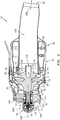
FIG. 1 is a partially schematic front view of an attritable gas turbine engine. -
FIG. 2 is a partially schematic axial sectional view of the engine ofFIG. 1 taken along line 2-2. -
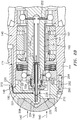
FIG. 2A is an enlarged view of a forward portion of the engine ofFIG. 2 . -
FIG. 2B is a further enlarged view of the forward portion of the engine ofFIG. 2 . -
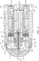
FIG. 3 is an enlarged view of the forward portion taken along line 3-3 ofFIG. 1 . -
FIG. 4 is a cutaway view of a nose cap. -
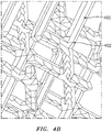
FIGs. 4A and4B are further enlarged views of the nose cap. - Like reference numbers and designations in the various drawings indicate like elements.
-
FIG. 1 shows agas turbine engine 20 based on the aforementioned TJ-150™ engine. The key difference is the presence of a unitarily-formednose cap 200. The engine has a core centerline 500 (FIG. 2 ) which serves as an axis of rotation of one ormore spools 24 relative to acase 26. As is discussed further below, the exemplary engine is a single-spool attritable turbine engine, namely a turbojet. Thecase 26 is formed as an axial assembly of multiple pieces (e.g., castings). A primary gas flowpath (gaspath) 502 extends from aninlet 27 to anoutlet 28. Along thegaspath 502, theinlet gas flow 504 is an air flow and the outlet (exhaust)flow 506 is an exhaust gas flow. At a front or forward end of the engine (e.g., shown surrounded by the inlet 27) is aninlet centerbody 29. - The
exemplary gaspath 502 passes sequentially through a compressor section (compressor) 30, acombustor section 32, and aturbine section 34. The exemplary compressor and turbine sections respectively have acentrifugal impeller 36 andcentrifugal turbine 38. The impeller and turbine haverespective hubs 40, 42 (FIG. 2A ) having gaspath-facingsurfaces vanes tips gaspath 502, therespective vanes - The
exemplary compressor 30 receives a generally axial air flow 504 (FIG. 2 ) along thegaspath 502 and redirects it partially radially outward. Upon exiting theimpeller 36 at the vane downstream ends 74, the air flow is redirected more axially rearward in adiffuser 80. Exiting the diffuser, the air flow enters thecombustor 32. Theexemplary combustor 32 is a reverse flow annular combustor wherein the air is combusted with fuel (introduced via manifold 90) and diverted back forward to enter theturbine 38 passing radially inward at the turbine vane upstream ends 72. Passing along theturbine 38, the combustion gases are expanded and redirected axially rearward to pass into anexhaust duct 100 and out theoutlet 28 as the outlet orexhaust flow 506. - The exemplary spool 24 (
FIG. 2A ) extends from a front orforward end 120 to a rear oraft end 122. Theimpeller 36 andturbine 38 are rearwardly cantilevered with thespool 24 supported by a pair ofbearings spool shaft 134. Theexemplary spool shaft 134 is unitarily formed with theturbine 38 with an intermediate portion of the spool shaft received in a bore of the impeller 36 (e.g., via splined or otherwise rotationally keyed interfitting). - The
exemplary bearings spool shaft 134 and outer races mounted to thecase 26. At theinlet 27, thecase 26 includes an inlet member (e.g., a casting) 140 having a circumferential array ofvanes 142 extending radially from aninner diameter hub 144 to an outerdiameter case portion 146. Theexemplary hub 144 forms a portion of the outer diameter contour of thecenterbody 29 and mounts the outer races ofbearings -
FIG. 2B further shows agenerator 160 including astator 162 mounted to theinlet member 140 and arotor 164 mounted to thespool shaft 134. Conventional electrical connections and the like are not shown.FIG. 2A further shows a conduit 170 (e.g., pipe) delivering afuel flow 530 along a fuel flowpath from a fuel source (e.g., tank and pump not shown) to aplenum 172 in the inlet member 140 (e.g., formed by a combination of casting and drilling followed by plugging access ports). Theplenum 172 has a first outlet branch orpassageway 174 for feeding a branch flow 532 (FIG. 2B ) to the bearings and asecond branch 176 for feeding a branch flow 534 (FIG. 3 ) to the bearings. In the illustrated example, thebranch flow 532 further branches intoflows forward bearing 130 and theaft bearing 132. Thebranch flow 534 merges with thebranch flow 532B to feed theaft bearing 132. In alternative embodiments, thebranch flow 532B or thebranch flow 534 may be omitted. Each of the branches orpassageways forward rim 148 of theinlet member 140. These ports register withports 220, 222 (FIGs. 2B and3 , respectively) on abody 202 of thenose cap 200. - The
nose cap body 202 includes acenterbody 204 within anaxial passageway 206 and a pair ofarms 208, 210 (FIG. 2B). FIGs. 2B and3 show therespective ports rear face 212 feedingrespective passageway legs 224, 226 (respectively continuingpassageways 174, 176). Theexemplary passageway leg 224 feeds a rearwardly open chamber 228 (FIG. 2B ) in thecenterbody 204. Thechamber 228 has a circular section rendered annular by the presence of a tube 230 (e.g., metallic) mounted (e.g., press-fit) to thecenterbody 204 and discussed further below. - The front bearing flow 532 passes out the annular opening of the
chamber 228 at anaft rim 232 thereof. It then proceeds through conventional feed passageways to thefront bearing 130. - The
tube 230 has alateral inlet port 240 open to a downstream end of thepassageway leg 226 to receive thebearing flow 534. An aft end portion of thetube 230 is nested within acentral passageway 250 in thespool shaft 134 forward portion. Thepassageway 250 hasradial outlet passageways 252 for feeding the combinedflow rear bearing 132. -
FIGs. 2 and3 further show a coolingair flow 540. The coolingair flow 540 passes through the nose cap (passageway 206), then through thefront bearing 130,generator 160, and aft bearing 132 to discharge radially as a fuel-laden air flow 542 merging with themain air flow 504 at the compressor inlet (to subsequently be compressed, receive further fuel, combusted, and expanded). - Whereas the baseline nose cap body of the TJ-150™ engine is separately formed from a layered mesh insert, the nose cap 200 (
FIG. 4 ) is formed as a single piece combination of a lattice portion (lattice) 260 and thenose cap body 202 surrounding the lattice portion. The combination is additively manufactured (e.g., via laser powder bed fusion or direct metal laser sintering (DMLS)) of an alloy (e.g., steel or an aluminum-silicon alloy such as AlSi10Mg). Thelattice 260 may be manufactured as a three-dimensional (3D) lattice structure (e.g., a bi-triangle lattice). A 3D lattice comprises individual lattice beams 400 (FIG. 4B - also known as legs or struts) extending between junctions 402 (nodes). Each junction may join three or more beams, with adjacent strut ends merging at the junction and the junction being centered at a lattice point (also known as a cell corner or node). An exemplary beam length may be circular (at least away from transitional regions at the beam ends/junctions). An exemplary beam length may be measured from junction center to junction center and include portions of the junction) or beam length may be measured from the junctions or node periphery. - Whereas the baseline layered wire mesh has generally constant thickness, the additive manufacture allows optimization of a varied thickness of the
lattice 260 to provide a combination of limited weight, structural integrity, and debris protection. - The
exemplary lattice 260 has a domed forward perimeter portion 262 (FIG. 4 ) (convex in two transverse directions) which may have a curvature following the domed curvature of an outer contour of thenose cap body 202. Thelattice 260 also has an aft surface orperimeter portion 266. - Although, in some embodiments, the
aft perimeter portion 266 may be flat transverse to thecenterline 500, such a configuration may be disadvantageous. It provides a maximum thickness at the centerline which may involve excessive flow resistance/restriction and excessive mass. In addition to the reduced flow from the flow resistance, the flow resistance also imparts axial loads which must be transmitted radially outward to the junction of the lattice and nose cap body. These loads impose mechanical stresses. - Accordingly, the exemplary configuration has a radially outwardly and rearwardly divergent
aft perimeter 266 profile shown as an essentially conical or frustoconical profile (half angle θ shown inFIG. 4 ). Exemplary θ is about 45°, more generally 40° to 50° or 30° to 60° or 20° to 70°. This configuration may render thelattice 260 relatively thin near thecenterline 500, thickening in the radial outward direction. This configuration may provide reduced flow resistance and weight while maintaining structural integrity. An axial span or thickness/depth of the lattice is shown as TL1 at the centerline increasing to a maximum value of TL2 at the radially inboard extreme of a downstream radial interface between lattice and nose cap body. Exemplary TL1 is 3.0 mm, more broadly at least 2.0 mm or 2.0 mm to 10.0 mm. Exemplary TL2 is 9.0 mm. In relative terms, exemplary TL1 is 75% or less of TL2, more particularly, 15% to 75% or 20% to 65% or 25% to 50%. - Exemplary lattice have individual beam cross-sectional transverse linear dimension (may be measured as the maximum cross-section dimension where it reaches a minimum. For example, the maximum of a hexagon is measured between opposite corners. If the hexagon changes size along the beam length, the measurement may be defined as the opposite corner measurement at the position of the smallest hexagonal section. The maximum is a diameter for a circular beam section. Such value may be up to 1.5 mm or 0.05 mm to 1.5 mm, more particularly 0.10 mm to 1.0 mm or 0.20 mm to 0.75 mm. Such exemplary lattice parameters may further have node center to node center beam length of up to 8.0 mm, more particularly 0.3 mm to 5.0 mm or 0.5 mm to 3.0 mm or 0.75 mm to 2.5 mm). Narrower exemplary ratios of said length to said transverse dimension are between 3:1 and 10:1.
- The exemplary lattice is a regular lattice (uniform cell structure and relative node position). Thus, the manufacture process may terminate beams along the fore and aft perimeters/
peripheries -
FIGs. 2B and3 further show a circumferential array of axialcounterbored mounting holes 290 in thenose cap body 202 receiving threaded fasteners (e.g., screws or bolts 292) extending into associated threadedaxial bores 294 open to theforward rim 148 of theinlet member 140. - The use of "first", "second", and the like in the following claims is for differentiation within the claim only and does not necessarily indicate relative or absolute importance or temporal order. Similarly, the identification in a claim of one element as "first" (or the like) does not preclude such "first" element from identifying an element that is referred to as "second" (or the like) in another claim or in the description.
- One or more embodiments have been described. Nevertheless, it will be understood that various modifications may be made. For example, when applied to an existing baseline screen or engine configuration, details of such baseline may influence details of particular implementations. Accordingly, other embodiments are within the scope of the following claims.
Claims (15)
- A turbine engine inlet member comprising a unitarily-formed single piece combination of:a three dimensional (3D) lattice portion (260); anda nose cap body (202) surrounding the lattice portion (260).
- The inlet member of claim 1 wherein the three dimensional lattice portion (260) has a domed forward perimeter portion (262).
- The inlet member of claim 1 or 2 wherein the three dimensional lattice portion (260) has a rearwardly divergent aft perimeter portion (266) and, optionally, wherein the aft perimeter portion (266) is conical or frustoconical.
- A turbine engine comprising:a compressor (30);a combustor (32);a turbine (34), a gas flowpath (502) passing consecutively through the compressor (30), combustor (32), and turbine (34); andthe inlet member (140) of claim 1 along the gas flowpath (502) upstream of the compressor (30).
- The turbine engine of claim 4 wherein:
the inlet member (140) is formed of steel or AlSi10Mg. - The turbine engine of claim 4 or 5 wherein:the lattice (260) is a regular lattice; orthe lattice (260) is a bi-triangle lattice.
- The turbine engine of claim 4, 5 or 6 wherein:the lattice (260) has a beam length measured node center to node center of 0.3 mm to 5.0 mm; and/orthe lattice (260) has a beam cross-sectional dimension of 0.05 mm to 1.5 mm.
- The turbine engine of any of claims 4-7 wherein:the lattice (260) has a domed forward perimeter portion (262) and a radially outwardly and rearwardly divergent aft perimeter portion (266); and, optionally,the aft perimeter portion (266) is conical.
- The turbine engine of any of claims 4-8 wherein:
the lattice portion (260) has an axial depth of at least 2.0 mm. - The turbine engine of any of claims 4-9 wherein:
the lattice portion (260) has an axial depth at an axial centerline of less than 75% of an axial depth at a location outboard of the centerline. - The turbine engine of any of claims 4-10 wherein:the nose cap body (202) comprises a plurality of mounting holes (290); anda plurality of threaded fasteners (292) mount a nose cap (200) to an inlet housing.
- The turbine engine of any of claims 4-11 wherein:
the engine is a single-spool engine. - The turbine engine of any of claims 4-12 wherein:the compressor (30) is a centrifugal compressor; andthe combustor (32) is a reverse flow combustor.
- A method for manufacturing the turbine engine of any of claims 4-13, the method comprising:additive manufacture of the inlet member (140); andassembling the inlet member (140) to an or the inlet housing.
- The method of claim 14 wherein:the assembling registers passageways of the nose cap body (224, 226) with passageways of the inlet housing (174, 176); and/orthe additive manufacture comprises laser powder bed fusion.
Applications Claiming Priority (1)
| Application Number | Priority Date | Filing Date | Title |
|---|---|---|---|
| US16/434,453 US11359543B2 (en) | 2019-06-07 | 2019-06-07 | Attritable engine additively manufactured inlet cap |
Publications (2)
| Publication Number | Publication Date |
|---|---|
| EP3748148A1 true EP3748148A1 (en) | 2020-12-09 |
| EP3748148B1 EP3748148B1 (en) | 2023-01-04 |
Family
ID=70802753
Family Applications (1)
| Application Number | Title | Priority Date | Filing Date |
|---|---|---|---|
| EP20175922.2A Active EP3748148B1 (en) | 2019-06-07 | 2020-05-21 | Attritable engine additively manufactured inlet cap |
Country Status (2)
| Country | Link |
|---|---|
| US (2) | US11359543B2 (en) |
| EP (1) | EP3748148B1 (en) |
Families Citing this family (5)
| Publication number | Priority date | Publication date | Assignee | Title |
|---|---|---|---|---|
| US12264624B2 (en) | 2022-06-10 | 2025-04-01 | Rtx Corporation | Build plate integrated into additive manufactured component |
| GB2637899A (en) * | 2023-10-12 | 2025-08-13 | Leonardo UK Ltd | An EMC fluid filter |
| US12385407B1 (en) | 2024-05-17 | 2025-08-12 | Rtx Corporation | Additively manufactured turbine vane cluster |
| US20260015945A1 (en) | 2024-07-09 | 2026-01-15 | Rtx Corporation | Diffuser-turbine flow network |
| US12529337B1 (en) | 2024-11-18 | 2026-01-20 | Rtx Corporation | Additively manufactured turbine engine case with fuel manifold |
Citations (3)
| Publication number | Priority date | Publication date | Assignee | Title |
|---|---|---|---|---|
| US20070028589A1 (en) * | 2005-08-03 | 2007-02-08 | Hamilton Sundstrand Corporation | Thermal management system for a gas turbine engine |
| US20140255202A1 (en) * | 2012-12-21 | 2014-09-11 | United Technologies Corporation | Turbine engine nosecone with deformation region |
| US20170009656A1 (en) * | 2014-02-28 | 2017-01-12 | Safran Aircraft Engines | Fan rotor for a turbo machine such as a multiple flow turbojet engine driven by a reduction gear |
Family Cites Families (14)
| Publication number | Priority date | Publication date | Assignee | Title |
|---|---|---|---|---|
| US4379191A (en) * | 1975-08-13 | 1983-04-05 | Rohr Industries, Inc. | Honeycomb noise attenuation structure |
| US4743740A (en) * | 1985-10-07 | 1988-05-10 | Rohr Industries, Inc. | Buried element deicer |
| US6527829B1 (en) * | 2000-03-15 | 2003-03-04 | Fortum Oyj | Method and arrangement for purifying the intake air of a gas turbine |
| US8215919B2 (en) * | 2008-02-22 | 2012-07-10 | Hamilton Sundstrand Corporation | Curved tooth coupling for a miniature gas turbine engine |
| US8262344B2 (en) * | 2008-04-02 | 2012-09-11 | Hamilton Sundstrand Corporation | Thermal management system for a gas turbine engine |
| US8440002B2 (en) * | 2010-05-27 | 2013-05-14 | General Electric Company | Long life pyramidal filter for gas turbine inlet system |
| US10634054B2 (en) * | 2014-10-21 | 2020-04-28 | United Technologies Corporation | Additive manufactured ducted heat exchanger |
| US10450954B2 (en) * | 2016-03-17 | 2019-10-22 | General Electric Company | Internally heated engine inlet screen for aircraft engines |
| US20170334571A1 (en) * | 2016-05-20 | 2017-11-23 | Depei Bai | Anti-bird strike protection net for aircraft jet engine |
| GB201703944D0 (en) * | 2017-01-24 | 2017-04-26 | Rolls Royce Plc | Gas turbine engine arrangement |
| PL420326A1 (en) * | 2017-01-27 | 2018-07-30 | General Electric Company Polska Spolka Z Ograniczona Odpowiedzialnoscia | Intake shield for aircraft engines |
| EP3444447A1 (en) * | 2017-08-14 | 2019-02-20 | General Electric Company | Inlet frame for a gas turbine engine |
| EP3444441B1 (en) | 2017-08-14 | 2020-04-08 | General Electric Company | Gas turbine engine with inlet frame |
| US11047305B2 (en) * | 2018-04-12 | 2021-06-29 | Stephanie Fraser-Beekman | Debris deflector for a jet engine |
-
2019
- 2019-06-07 US US16/434,453 patent/US11359543B2/en active Active
-
2020
- 2020-05-21 EP EP20175922.2A patent/EP3748148B1/en active Active
-
2022
- 2022-05-17 US US17/746,206 patent/US11739690B2/en active Active
Patent Citations (3)
| Publication number | Priority date | Publication date | Assignee | Title |
|---|---|---|---|---|
| US20070028589A1 (en) * | 2005-08-03 | 2007-02-08 | Hamilton Sundstrand Corporation | Thermal management system for a gas turbine engine |
| US20140255202A1 (en) * | 2012-12-21 | 2014-09-11 | United Technologies Corporation | Turbine engine nosecone with deformation region |
| US20170009656A1 (en) * | 2014-02-28 | 2017-01-12 | Safran Aircraft Engines | Fan rotor for a turbo machine such as a multiple flow turbojet engine driven by a reduction gear |
Also Published As
| Publication number | Publication date |
|---|---|
| EP3748148B1 (en) | 2023-01-04 |
| US11359543B2 (en) | 2022-06-14 |
| US11739690B2 (en) | 2023-08-29 |
| US20230077719A1 (en) | 2023-03-16 |
| US20200386160A1 (en) | 2020-12-10 |
Similar Documents
| Publication | Publication Date | Title |
|---|---|---|
| US11739690B2 (en) | Attritable engine additively manufactured inlet cap | |
| US10301960B2 (en) | Shroud assembly for gas turbine engine | |
| EP1608846B1 (en) | A method of manufacturing a stator component | |
| CA2964624C (en) | System and method for cooling components of a gas turbine engine | |
| US20130028718A1 (en) | Strut, a gas turbine engine frame comprising the strut and a gas turbine engine comprising the frame | |
| EP2963346B1 (en) | Self-cooled orifice structure | |
| US10443848B2 (en) | Grommet assembly and method of design | |
| EP3026343A1 (en) | Self-cooled orifice structure | |
| US10233836B2 (en) | Turbomachine combustion chamber provided with air deflection means for reducing the wake created by an ignition plug | |
| US11549437B2 (en) | Combustor for gas turbine engine and method of manufacture | |
| EP3604927B1 (en) | Liner assembly for use in a combustor of a gas turbine engine combustor panel | |
| US10247011B2 (en) | Gas turbine engine component with increased cooling capacity | |
| CN113503564B (en) | Combustor for use in a turbine engine | |
| EP3450696B1 (en) | Segmented conduit with airfoil geometry | |
| CN107795342B (en) | Intermediate casing for a turbine wheel | |
| US10047609B2 (en) | Airfoil array with airfoils that differ in geometry according to geometry classes | |
| US11754342B2 (en) | Bypass air/fluid heat exchanger, method for manufacturing same and turbofan engine provided with such exchanger | |
| EP4299881B1 (en) | Scoop assembly for rotational equipment | |
| EP4163499A1 (en) | Diffuser and deswirl system with integral tangential on-board injector for engine | |
| US9988943B2 (en) | Fitting for mid-turbine frame of gas turbine engine | |
| US9239166B2 (en) | Gas turbine diffuser with flow separator | |
| US12618362B2 (en) | Methods and apparatus to provide cross-diffuser bleed | |
| US20260022656A1 (en) | Methods and apparatus to provide cross-diffuser bleed | |
| US20260022657A1 (en) | Methods and apparatus to provide cross-diffuser bleed | |
| US20240060459A1 (en) | Exhaust assembly for purging a nacelle cavity of a propulsion system |
Legal Events
| Date | Code | Title | Description |
|---|---|---|---|
| PUAI | Public reference made under article 153(3) epc to a published international application that has entered the european phase |
Free format text: ORIGINAL CODE: 0009012 |
|
| STAA | Information on the status of an ep patent application or granted ep patent |
Free format text: STATUS: THE APPLICATION HAS BEEN PUBLISHED |
|
| AK | Designated contracting states |
Kind code of ref document: A1 Designated state(s): AL AT BE BG CH CY CZ DE DK EE ES FI FR GB GR HR HU IE IS IT LI LT LU LV MC MK MT NL NO PL PT RO RS SE SI SK SM TR |
|
| AX | Request for extension of the european patent |
Extension state: BA ME |
|
| STAA | Information on the status of an ep patent application or granted ep patent |
Free format text: STATUS: REQUEST FOR EXAMINATION WAS MADE |
|
| 17P | Request for examination filed |
Effective date: 20210608 |
|
| RBV | Designated contracting states (corrected) |
Designated state(s): AL AT BE BG CH CY CZ DE DK EE ES FI FR GB GR HR HU IE IS IT LI LT LU LV MC MK MT NL NO PL PT RO RS SE SI SK SM TR |
|
| RIC1 | Information provided on ipc code assigned before grant |
Ipc: B64D 33/02 20060101ALI20220531BHEP Ipc: B33Y 80/00 20150101ALI20220531BHEP Ipc: B64C 11/14 20060101ALI20220531BHEP Ipc: F02C 7/14 20060101ALI20220531BHEP Ipc: F02C 7/055 20060101AFI20220531BHEP |
|
| GRAP | Despatch of communication of intention to grant a patent |
Free format text: ORIGINAL CODE: EPIDOSNIGR1 |
|
| STAA | Information on the status of an ep patent application or granted ep patent |
Free format text: STATUS: GRANT OF PATENT IS INTENDED |
|
| INTG | Intention to grant announced |
Effective date: 20220718 |
|
| GRAS | Grant fee paid |
Free format text: ORIGINAL CODE: EPIDOSNIGR3 |
|
| GRAA | (expected) grant |
Free format text: ORIGINAL CODE: 0009210 |
|
| STAA | Information on the status of an ep patent application or granted ep patent |
Free format text: STATUS: THE PATENT HAS BEEN GRANTED |
|
| AK | Designated contracting states |
Kind code of ref document: B1 Designated state(s): AL AT BE BG CH CY CZ DE DK EE ES FI FR GB GR HR HU IE IS IT LI LT LU LV MC MK MT NL NO PL PT RO RS SE SI SK SM TR |
|
| REG | Reference to a national code |
Ref country code: GB Ref legal event code: FG4D |
|
| REG | Reference to a national code |
Ref country code: CH Ref legal event code: EP |
|
| REG | Reference to a national code |
Ref country code: AT Ref legal event code: REF Ref document number: 1542080 Country of ref document: AT Kind code of ref document: T Effective date: 20230115 |
|
| REG | Reference to a national code |
Ref country code: DE Ref legal event code: R096 Ref document number: 602020007293 Country of ref document: DE |
|
| REG | Reference to a national code |
Ref country code: IE Ref legal event code: FG4D |
|
| REG | Reference to a national code |
Ref country code: LT Ref legal event code: MG9D |
|
| REG | Reference to a national code |
Ref country code: NL Ref legal event code: MP Effective date: 20230104 |
|
| REG | Reference to a national code |
Ref country code: AT Ref legal event code: MK05 Ref document number: 1542080 Country of ref document: AT Kind code of ref document: T Effective date: 20230104 |
|
| P01 | Opt-out of the competence of the unified patent court (upc) registered |
Effective date: 20230521 |
|
| PG25 | Lapsed in a contracting state [announced via postgrant information from national office to epo] |
Ref country code: NL Free format text: LAPSE BECAUSE OF FAILURE TO SUBMIT A TRANSLATION OF THE DESCRIPTION OR TO PAY THE FEE WITHIN THE PRESCRIBED TIME-LIMIT Effective date: 20230104 |
|
| PG25 | Lapsed in a contracting state [announced via postgrant information from national office to epo] |
Ref country code: RS Free format text: LAPSE BECAUSE OF FAILURE TO SUBMIT A TRANSLATION OF THE DESCRIPTION OR TO PAY THE FEE WITHIN THE PRESCRIBED TIME-LIMIT Effective date: 20230104 Ref country code: PT Free format text: LAPSE BECAUSE OF FAILURE TO SUBMIT A TRANSLATION OF THE DESCRIPTION OR TO PAY THE FEE WITHIN THE PRESCRIBED TIME-LIMIT Effective date: 20230504 Ref country code: NO Free format text: LAPSE BECAUSE OF FAILURE TO SUBMIT A TRANSLATION OF THE DESCRIPTION OR TO PAY THE FEE WITHIN THE PRESCRIBED TIME-LIMIT Effective date: 20230404 Ref country code: LV Free format text: LAPSE BECAUSE OF FAILURE TO SUBMIT A TRANSLATION OF THE DESCRIPTION OR TO PAY THE FEE WITHIN THE PRESCRIBED TIME-LIMIT Effective date: 20230104 Ref country code: LT Free format text: LAPSE BECAUSE OF FAILURE TO SUBMIT A TRANSLATION OF THE DESCRIPTION OR TO PAY THE FEE WITHIN THE PRESCRIBED TIME-LIMIT Effective date: 20230104 Ref country code: HR Free format text: LAPSE BECAUSE OF FAILURE TO SUBMIT A TRANSLATION OF THE DESCRIPTION OR TO PAY THE FEE WITHIN THE PRESCRIBED TIME-LIMIT Effective date: 20230104 Ref country code: ES Free format text: LAPSE BECAUSE OF FAILURE TO SUBMIT A TRANSLATION OF THE DESCRIPTION OR TO PAY THE FEE WITHIN THE PRESCRIBED TIME-LIMIT Effective date: 20230104 Ref country code: AT Free format text: LAPSE BECAUSE OF FAILURE TO SUBMIT A TRANSLATION OF THE DESCRIPTION OR TO PAY THE FEE WITHIN THE PRESCRIBED TIME-LIMIT Effective date: 20230104 |
|
| PG25 | Lapsed in a contracting state [announced via postgrant information from national office to epo] |
Ref country code: SE Free format text: LAPSE BECAUSE OF FAILURE TO SUBMIT A TRANSLATION OF THE DESCRIPTION OR TO PAY THE FEE WITHIN THE PRESCRIBED TIME-LIMIT Effective date: 20230104 Ref country code: PL Free format text: LAPSE BECAUSE OF FAILURE TO SUBMIT A TRANSLATION OF THE DESCRIPTION OR TO PAY THE FEE WITHIN THE PRESCRIBED TIME-LIMIT Effective date: 20230104 Ref country code: IS Free format text: LAPSE BECAUSE OF FAILURE TO SUBMIT A TRANSLATION OF THE DESCRIPTION OR TO PAY THE FEE WITHIN THE PRESCRIBED TIME-LIMIT Effective date: 20230504 Ref country code: GR Free format text: LAPSE BECAUSE OF FAILURE TO SUBMIT A TRANSLATION OF THE DESCRIPTION OR TO PAY THE FEE WITHIN THE PRESCRIBED TIME-LIMIT Effective date: 20230405 Ref country code: FI Free format text: LAPSE BECAUSE OF FAILURE TO SUBMIT A TRANSLATION OF THE DESCRIPTION OR TO PAY THE FEE WITHIN THE PRESCRIBED TIME-LIMIT Effective date: 20230104 |
|
| REG | Reference to a national code |
Ref country code: DE Ref legal event code: R097 Ref document number: 602020007293 Country of ref document: DE |
|
| PG25 | Lapsed in a contracting state [announced via postgrant information from national office to epo] |
Ref country code: SM Free format text: LAPSE BECAUSE OF FAILURE TO SUBMIT A TRANSLATION OF THE DESCRIPTION OR TO PAY THE FEE WITHIN THE PRESCRIBED TIME-LIMIT Effective date: 20230104 Ref country code: RO Free format text: LAPSE BECAUSE OF FAILURE TO SUBMIT A TRANSLATION OF THE DESCRIPTION OR TO PAY THE FEE WITHIN THE PRESCRIBED TIME-LIMIT Effective date: 20230104 Ref country code: EE Free format text: LAPSE BECAUSE OF FAILURE TO SUBMIT A TRANSLATION OF THE DESCRIPTION OR TO PAY THE FEE WITHIN THE PRESCRIBED TIME-LIMIT Effective date: 20230104 Ref country code: DK Free format text: LAPSE BECAUSE OF FAILURE TO SUBMIT A TRANSLATION OF THE DESCRIPTION OR TO PAY THE FEE WITHIN THE PRESCRIBED TIME-LIMIT Effective date: 20230104 Ref country code: CZ Free format text: LAPSE BECAUSE OF FAILURE TO SUBMIT A TRANSLATION OF THE DESCRIPTION OR TO PAY THE FEE WITHIN THE PRESCRIBED TIME-LIMIT Effective date: 20230104 |
|
| RAP4 | Party data changed (patent owner data changed or rights of a patent transferred) |
Owner name: RTX CORPORATION |
|
| PLBE | No opposition filed within time limit |
Free format text: ORIGINAL CODE: 0009261 |
|
| STAA | Information on the status of an ep patent application or granted ep patent |
Free format text: STATUS: NO OPPOSITION FILED WITHIN TIME LIMIT |
|
| PG25 | Lapsed in a contracting state [announced via postgrant information from national office to epo] |
Ref country code: SK Free format text: LAPSE BECAUSE OF FAILURE TO SUBMIT A TRANSLATION OF THE DESCRIPTION OR TO PAY THE FEE WITHIN THE PRESCRIBED TIME-LIMIT Effective date: 20230104 |
|
| 26N | No opposition filed |
Effective date: 20231005 |
|
| REG | Reference to a national code |
Ref country code: CH Ref legal event code: PL |
|
| PG25 | Lapsed in a contracting state [announced via postgrant information from national office to epo] |
Ref country code: MC Free format text: LAPSE BECAUSE OF FAILURE TO SUBMIT A TRANSLATION OF THE DESCRIPTION OR TO PAY THE FEE WITHIN THE PRESCRIBED TIME-LIMIT Effective date: 20230104 |
|
| REG | Reference to a national code |
Ref country code: BE Ref legal event code: MM Effective date: 20230531 |
|
| PG25 | Lapsed in a contracting state [announced via postgrant information from national office to epo] |
Ref country code: SI Free format text: LAPSE BECAUSE OF FAILURE TO SUBMIT A TRANSLATION OF THE DESCRIPTION OR TO PAY THE FEE WITHIN THE PRESCRIBED TIME-LIMIT Effective date: 20230104 Ref country code: MC Free format text: LAPSE BECAUSE OF FAILURE TO SUBMIT A TRANSLATION OF THE DESCRIPTION OR TO PAY THE FEE WITHIN THE PRESCRIBED TIME-LIMIT Effective date: 20230104 Ref country code: LU Free format text: LAPSE BECAUSE OF NON-PAYMENT OF DUE FEES Effective date: 20230521 Ref country code: LI Free format text: LAPSE BECAUSE OF NON-PAYMENT OF DUE FEES Effective date: 20230531 Ref country code: CH Free format text: LAPSE BECAUSE OF NON-PAYMENT OF DUE FEES Effective date: 20230531 |
|
| REG | Reference to a national code |
Ref country code: IE Ref legal event code: MM4A |
|
| PG25 | Lapsed in a contracting state [announced via postgrant information from national office to epo] |
Ref country code: IE Free format text: LAPSE BECAUSE OF NON-PAYMENT OF DUE FEES Effective date: 20230521 |
|
| PG25 | Lapsed in a contracting state [announced via postgrant information from national office to epo] |
Ref country code: IE Free format text: LAPSE BECAUSE OF NON-PAYMENT OF DUE FEES Effective date: 20230521 |
|
| PG25 | Lapsed in a contracting state [announced via postgrant information from national office to epo] |
Ref country code: IT Free format text: LAPSE BECAUSE OF FAILURE TO SUBMIT A TRANSLATION OF THE DESCRIPTION OR TO PAY THE FEE WITHIN THE PRESCRIBED TIME-LIMIT Effective date: 20230104 Ref country code: BE Free format text: LAPSE BECAUSE OF NON-PAYMENT OF DUE FEES Effective date: 20230531 |
|
| PG25 | Lapsed in a contracting state [announced via postgrant information from national office to epo] |
Ref country code: BG Free format text: LAPSE BECAUSE OF FAILURE TO SUBMIT A TRANSLATION OF THE DESCRIPTION OR TO PAY THE FEE WITHIN THE PRESCRIBED TIME-LIMIT Effective date: 20230104 |
|
| PG25 | Lapsed in a contracting state [announced via postgrant information from national office to epo] |
Ref country code: BG Free format text: LAPSE BECAUSE OF FAILURE TO SUBMIT A TRANSLATION OF THE DESCRIPTION OR TO PAY THE FEE WITHIN THE PRESCRIBED TIME-LIMIT Effective date: 20230104 |
|
| PGFP | Annual fee paid to national office [announced via postgrant information from national office to epo] |
Ref country code: DE Payment date: 20250423 Year of fee payment: 6 |
|
| PGFP | Annual fee paid to national office [announced via postgrant information from national office to epo] |
Ref country code: GB Payment date: 20250423 Year of fee payment: 6 |
|
| PGFP | Annual fee paid to national office [announced via postgrant information from national office to epo] |
Ref country code: FR Payment date: 20250423 Year of fee payment: 6 |
|
| PG25 | Lapsed in a contracting state [announced via postgrant information from national office to epo] |
Ref country code: CY Free format text: LAPSE BECAUSE OF FAILURE TO SUBMIT A TRANSLATION OF THE DESCRIPTION OR TO PAY THE FEE WITHIN THE PRESCRIBED TIME-LIMIT; INVALID AB INITIO Effective date: 20200521 |
|
| PG25 | Lapsed in a contracting state [announced via postgrant information from national office to epo] |
Ref country code: HU Free format text: LAPSE BECAUSE OF FAILURE TO SUBMIT A TRANSLATION OF THE DESCRIPTION OR TO PAY THE FEE WITHIN THE PRESCRIBED TIME-LIMIT; INVALID AB INITIO Effective date: 20200521 |
|
| REG | Reference to a national code |
Ref country code: DE Ref legal event code: R081 Ref document number: 602020007293 Country of ref document: DE Owner name: RTX CORPORATION (N.D.GES.D. STAATES DELAWARE),, US Free format text: FORMER OWNER: RAYTHEON TECHNOLOGIES CORP., FARMINGTON, CT, US |
|
| PG25 | Lapsed in a contracting state [announced via postgrant information from national office to epo] |
Ref country code: TR Free format text: LAPSE BECAUSE OF FAILURE TO SUBMIT A TRANSLATION OF THE DESCRIPTION OR TO PAY THE FEE WITHIN THE PRESCRIBED TIME-LIMIT Effective date: 20230104 |