EP3747850A1 - Systems and methods for infiltrating porous ceramic matrix composite (cmc) preforms - Google Patents
Systems and methods for infiltrating porous ceramic matrix composite (cmc) preforms Download PDFInfo
- Publication number
- EP3747850A1 EP3747850A1 EP20177618.4A EP20177618A EP3747850A1 EP 3747850 A1 EP3747850 A1 EP 3747850A1 EP 20177618 A EP20177618 A EP 20177618A EP 3747850 A1 EP3747850 A1 EP 3747850A1
- Authority
- EP
- European Patent Office
- Prior art keywords
- molten
- densifier
- flow direction
- cmc
- cmc preform
- Prior art date
- Legal status (The legal status is an assumption and is not a legal conclusion. Google has not performed a legal analysis and makes no representation as to the accuracy of the status listed.)
- Granted
Links
Images



Classifications
-
- C—CHEMISTRY; METALLURGY
- C04—CEMENTS; CONCRETE; ARTIFICIAL STONE; CERAMICS; REFRACTORIES
- C04B—LIME, MAGNESIA; SLAG; CEMENTS; COMPOSITIONS THEREOF, e.g. MORTARS, CONCRETE OR LIKE BUILDING MATERIALS; ARTIFICIAL STONE; CERAMICS; REFRACTORIES; TREATMENT OF NATURAL STONE
- C04B35/00—Shaped ceramic products characterised by their composition; Ceramics compositions; Processing powders of inorganic compounds preparatory to the manufacturing of ceramic products
- C04B35/71—Ceramic products containing macroscopic reinforcing agents
- C04B35/78—Ceramic products containing macroscopic reinforcing agents containing non-metallic materials
- C04B35/80—Fibres, filaments, whiskers, platelets, or the like
-
- C—CHEMISTRY; METALLURGY
- C04—CEMENTS; CONCRETE; ARTIFICIAL STONE; CERAMICS; REFRACTORIES
- C04B—LIME, MAGNESIA; SLAG; CEMENTS; COMPOSITIONS THEREOF, e.g. MORTARS, CONCRETE OR LIKE BUILDING MATERIALS; ARTIFICIAL STONE; CERAMICS; REFRACTORIES; TREATMENT OF NATURAL STONE
- C04B41/00—After-treatment of mortars, concrete, artificial stone or ceramics; Treatment of natural stone
- C04B41/45—Coating or impregnating, e.g. injection in masonry, partial coating of green or fired ceramics, organic coating compositions for adhering together two concrete elements
- C04B41/4505—Coating or impregnating, e.g. injection in masonry, partial coating of green or fired ceramics, organic coating compositions for adhering together two concrete elements characterised by the method of application
- C04B41/4523—Coating or impregnating, e.g. injection in masonry, partial coating of green or fired ceramics, organic coating compositions for adhering together two concrete elements characterised by the method of application applied from the molten state ; Thermal spraying, e.g. plasma spraying
-
- B—PERFORMING OPERATIONS; TRANSPORTING
- B28—WORKING CEMENT, CLAY, OR STONE
- B28B—SHAPING CLAY OR OTHER CERAMIC COMPOSITIONS; SHAPING SLAG; SHAPING MIXTURES CONTAINING CEMENTITIOUS MATERIAL, e.g. PLASTER
- B28B1/00—Producing shaped prefabricated articles from the material
- B28B1/24—Producing shaped prefabricated articles from the material by injection moulding
-
- B—PERFORMING OPERATIONS; TRANSPORTING
- B28—WORKING CEMENT, CLAY, OR STONE
- B28B—SHAPING CLAY OR OTHER CERAMIC COMPOSITIONS; SHAPING SLAG; SHAPING MIXTURES CONTAINING CEMENTITIOUS MATERIAL, e.g. PLASTER
- B28B23/00—Arrangements specially adapted for the production of shaped articles with elements wholly or partly embedded in the moulding material; Production of reinforced objects
- B28B23/0006—Arrangements specially adapted for the production of shaped articles with elements wholly or partly embedded in the moulding material; Production of reinforced objects the reinforcement consisting of aligned, non-metal reinforcing elements
-
- C—CHEMISTRY; METALLURGY
- C04—CEMENTS; CONCRETE; ARTIFICIAL STONE; CERAMICS; REFRACTORIES
- C04B—LIME, MAGNESIA; SLAG; CEMENTS; COMPOSITIONS THEREOF, e.g. MORTARS, CONCRETE OR LIKE BUILDING MATERIALS; ARTIFICIAL STONE; CERAMICS; REFRACTORIES; TREATMENT OF NATURAL STONE
- C04B35/00—Shaped ceramic products characterised by their composition; Ceramics compositions; Processing powders of inorganic compounds preparatory to the manufacturing of ceramic products
- C04B35/622—Forming processes; Processing powders of inorganic compounds preparatory to the manufacturing of ceramic products
- C04B35/64—Burning or sintering processes
- C04B35/65—Reaction sintering of free metal- or free silicon-containing compositions
-
- C—CHEMISTRY; METALLURGY
- C04—CEMENTS; CONCRETE; ARTIFICIAL STONE; CERAMICS; REFRACTORIES
- C04B—LIME, MAGNESIA; SLAG; CEMENTS; COMPOSITIONS THEREOF, e.g. MORTARS, CONCRETE OR LIKE BUILDING MATERIALS; ARTIFICIAL STONE; CERAMICS; REFRACTORIES; TREATMENT OF NATURAL STONE
- C04B41/00—After-treatment of mortars, concrete, artificial stone or ceramics; Treatment of natural stone
- C04B41/009—After-treatment of mortars, concrete, artificial stone or ceramics; Treatment of natural stone characterised by the material treated
-
- C—CHEMISTRY; METALLURGY
- C04—CEMENTS; CONCRETE; ARTIFICIAL STONE; CERAMICS; REFRACTORIES
- C04B—LIME, MAGNESIA; SLAG; CEMENTS; COMPOSITIONS THEREOF, e.g. MORTARS, CONCRETE OR LIKE BUILDING MATERIALS; ARTIFICIAL STONE; CERAMICS; REFRACTORIES; TREATMENT OF NATURAL STONE
- C04B41/00—After-treatment of mortars, concrete, artificial stone or ceramics; Treatment of natural stone
- C04B41/45—Coating or impregnating, e.g. injection in masonry, partial coating of green or fired ceramics, organic coating compositions for adhering together two concrete elements
- C04B41/4505—Coating or impregnating, e.g. injection in masonry, partial coating of green or fired ceramics, organic coating compositions for adhering together two concrete elements characterised by the method of application
- C04B41/4515—Coating or impregnating, e.g. injection in masonry, partial coating of green or fired ceramics, organic coating compositions for adhering together two concrete elements characterised by the method of application application under vacuum or reduced pressure
-
- C—CHEMISTRY; METALLURGY
- C04—CEMENTS; CONCRETE; ARTIFICIAL STONE; CERAMICS; REFRACTORIES
- C04B—LIME, MAGNESIA; SLAG; CEMENTS; COMPOSITIONS THEREOF, e.g. MORTARS, CONCRETE OR LIKE BUILDING MATERIALS; ARTIFICIAL STONE; CERAMICS; REFRACTORIES; TREATMENT OF NATURAL STONE
- C04B41/00—After-treatment of mortars, concrete, artificial stone or ceramics; Treatment of natural stone
- C04B41/80—After-treatment of mortars, concrete, artificial stone or ceramics; Treatment of natural stone of only ceramics
- C04B41/81—Coating or impregnation
- C04B41/85—Coating or impregnation with inorganic materials
-
- C—CHEMISTRY; METALLURGY
- C04—CEMENTS; CONCRETE; ARTIFICIAL STONE; CERAMICS; REFRACTORIES
- C04B—LIME, MAGNESIA; SLAG; CEMENTS; COMPOSITIONS THEREOF, e.g. MORTARS, CONCRETE OR LIKE BUILDING MATERIALS; ARTIFICIAL STONE; CERAMICS; REFRACTORIES; TREATMENT OF NATURAL STONE
- C04B2235/00—Aspects relating to ceramic starting mixtures or sintered ceramic products
- C04B2235/02—Composition of constituents of the starting material or of secondary phases of the final product
- C04B2235/30—Constituents and secondary phases not being of a fibrous nature
- C04B2235/42—Non metallic elements added as constituents or additives, e.g. sulfur, phosphor, selenium or tellurium
- C04B2235/428—Silicon
-
- C—CHEMISTRY; METALLURGY
- C04—CEMENTS; CONCRETE; ARTIFICIAL STONE; CERAMICS; REFRACTORIES
- C04B—LIME, MAGNESIA; SLAG; CEMENTS; COMPOSITIONS THEREOF, e.g. MORTARS, CONCRETE OR LIKE BUILDING MATERIALS; ARTIFICIAL STONE; CERAMICS; REFRACTORIES; TREATMENT OF NATURAL STONE
- C04B2235/00—Aspects relating to ceramic starting mixtures or sintered ceramic products
- C04B2235/02—Composition of constituents of the starting material or of secondary phases of the final product
- C04B2235/50—Constituents or additives of the starting mixture chosen for their shape or used because of their shape or their physical appearance
- C04B2235/52—Constituents or additives characterised by their shapes
- C04B2235/5208—Fibers
- C04B2235/5252—Fibers having a specific pre-form
-
- C—CHEMISTRY; METALLURGY
- C04—CEMENTS; CONCRETE; ARTIFICIAL STONE; CERAMICS; REFRACTORIES
- C04B—LIME, MAGNESIA; SLAG; CEMENTS; COMPOSITIONS THEREOF, e.g. MORTARS, CONCRETE OR LIKE BUILDING MATERIALS; ARTIFICIAL STONE; CERAMICS; REFRACTORIES; TREATMENT OF NATURAL STONE
- C04B2235/00—Aspects relating to ceramic starting mixtures or sintered ceramic products
- C04B2235/02—Composition of constituents of the starting material or of secondary phases of the final product
- C04B2235/50—Constituents or additives of the starting mixture chosen for their shape or used because of their shape or their physical appearance
- C04B2235/52—Constituents or additives characterised by their shapes
- C04B2235/5208—Fibers
- C04B2235/5268—Orientation of the fibers
-
- C—CHEMISTRY; METALLURGY
- C04—CEMENTS; CONCRETE; ARTIFICIAL STONE; CERAMICS; REFRACTORIES
- C04B—LIME, MAGNESIA; SLAG; CEMENTS; COMPOSITIONS THEREOF, e.g. MORTARS, CONCRETE OR LIKE BUILDING MATERIALS; ARTIFICIAL STONE; CERAMICS; REFRACTORIES; TREATMENT OF NATURAL STONE
- C04B2235/00—Aspects relating to ceramic starting mixtures or sintered ceramic products
- C04B2235/60—Aspects relating to the preparation, properties or mechanical treatment of green bodies or pre-forms
- C04B2235/602—Making the green bodies or pre-forms by moulding
- C04B2235/6022—Injection moulding
-
- C—CHEMISTRY; METALLURGY
- C04—CEMENTS; CONCRETE; ARTIFICIAL STONE; CERAMICS; REFRACTORIES
- C04B—LIME, MAGNESIA; SLAG; CEMENTS; COMPOSITIONS THEREOF, e.g. MORTARS, CONCRETE OR LIKE BUILDING MATERIALS; ARTIFICIAL STONE; CERAMICS; REFRACTORIES; TREATMENT OF NATURAL STONE
- C04B2235/00—Aspects relating to ceramic starting mixtures or sintered ceramic products
- C04B2235/60—Aspects relating to the preparation, properties or mechanical treatment of green bodies or pre-forms
- C04B2235/616—Liquid infiltration of green bodies or pre-forms
Definitions
- the disclosure relates generally to ceramic matrix composite (CMC) articles, and more particularly, to systems and methods for infiltrating porous CMC preforms to form CMC articles.
- CMC ceramic matrix composite
- Ceramic matrix composite (CMC) articles are generally considered well suited for structural components of a turbine engine due to, for example, their thermal resistance, high temperature strength, and chemical stability.
- CMC articles in a turbine engine can suffer from damage due to overstressing, excessive temperatures, improper formation, etc.
- One technique for addressing the damage-prone nature of the CMC articles is densification.
- conventional systems and methods for performing densification can create, for example, obstructions, cracks, and/or areas of reduced material and cause weaknesses within the CMC article.
- Conventional techniques for casting parts include injection molding, high pressure die casting, and low pressure die casting.
- none of these conventional techniques for casting have been utilized to perform the densification process on CMC articles because the operational parameters for performing the techniques may increase the likelihood and/or may cause damage to the CMC articles when performing the densification process.
- a first aspect of the disclosure provides a method for infiltrating a porous ceramic matrix composite (CMC) preform.
- the method includes: positioning the porous CMC preform in an opening of a die set for an infiltration system, the CMC preform including: a plurality of ply stacks, each of the plurality of ply stacks including a predetermined, unidirectional material orientation, and a plurality of voids formed between each of the plurality of ply stacks; flowing a molten densifier over the porous CMC preform in a first flow direction to infiltrate the plurality of voids formed between each of the plurality of ply stacks of the CMC preform; and flowing the molten densifier over the porous CMC preform in a second flow direction, distinct from the first flow direction, to infiltrate the plurality of voids formed between each of the plurality of ply stacks of the CMC preform, wherein the second flow direction is substantially parallel to the predetermined, un
- a second aspect of the disclosure provides a system including: a die set including an opening for receiving a porous ceramic matrix composite (CMC) preform; a first molten densifier supply conduit in communication with the opening of the die set in a first location of the die set, the first molten densifier supply conduit flowing a molten densifier to the opening of the die set in a first flow direction to infiltrate a plurality of voids formed between each of a plurality of ply stacks of the CMC preform; and a second molten densifier supply conduit in communication with the opening of the die set in a second location of the die set, the second molten densifier supply conduit flowing the molten densifier to the opening of the die set in a second flow direction substantially parallel to a predetermined, unidirectional material orientation of at least one ply stack of the plurality of ply stacks of the CMC preform to infiltrate the plurality of voids formed between each of the plurality of ply stack
- the disclosure relates generally to ceramic matrix composite (CMC) articles, and more particularly, to systems and methods for infiltrating porous CMC preforms to form CMC articles.
- CMC ceramic matrix composite
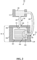
- FIGs. 1 and 2 show various views of a system 100 capable of infiltrating a porous ceramic matrix composite (CMC) preform 102 (hereafter, "CMC preform 102") included therein. More specifically, FIG. 1 shows a schematic view of system 100 and CMC preform 102 (shown in phantom) and FIG. 2 shows a front cross-section view of system 100 and CMC preform 102 taken along line 2-2 in FIG. 1 .
- CMC preform 102 porous ceramic matrix composite
- system 100 may be configured to flow a molten densifier over CMC preform 102 to infiltrate and/or densify preform 102 to create a CMC article (not shown) that may be utilized in various systems and/or devices (e.g., hot gas path components in turbine systems).
- a molten densifier over CMC preform 102 to infiltrate and/or densify preform 102 to create a CMC article (not shown) that may be utilized in various systems and/or devices (e.g., hot gas path components in turbine systems).
- System 100 may include a die set 104 configured to receive preform 102 for infiltration, as discussed herein.
- die set 104 may include a first portion 106 and a second portion 108 positioned on and/or coupled to first portion 106.
- Die set 104 may also include opening 110 formed therein.
- opening 110 may be formed in first portion 106 and/or may be formed between first portion 106 and second portion 108 of die set 104. As shown in FIGs. 1 and 2 , opening 110 may receive, house, and/or hold CMC preform 102 during the infiltration process performed using system 100.
- Die set 104 may be formed from any suitable material that may receive CMC preform 102 and withstand the pressures and/or material exposure temperatures (e.g., molten densifier) experienced when performing the infiltration process on CMC preform 102, as discussed herein. Additionally, although opening 110 of die set 104 is shown as be substantially polygonal/quadrilateral, it is understood that opening 110 may be formed as and/or may include any configuration for receiving CMC preform 102 to perform the infiltration process.
- material exposure temperatures e.g., molten densifier
- system 100 may also include at least one molten densifier source 112.
- Molten densifier source 112 of system 100 may hold, contain, and/or store a molten densifier 118 ( FIG. 2 ) that may be supplied to, flow over, and/or infiltrate CMC preform 102 during the infiltration process, as discussed herein.
- Molten densifier 118 may include any suitable molten source of a compound or composition capable of infiltrating CMC preform 102 and/or increasing the density of CMC preform 102 to form a CMC article (not shown).
- molten densifier 118 may include one or more molten sources of silicon.
- a single molten densifier source 112 is shown in FIGs. 1 and 2 , it is understood that system 100 may include more sources for providing molten densifier 118 to opening 110 of die set 104 during the infiltration process ( FIG. 9 ).
- Molten densifier source 112 may be in communication with die set 104 via a plurality of supply conduits.
- molten densifier source 112 may be in communication with a first molten densifier supply conduit 120 (hereafter, "first supply conduit 120").
- First supply conduit 120 may also be in communication with opening 110 of die set 104 and/or may couple molten densifier source 112 to opening 110 of die set 104.
- first supply conduit 120 may provide, supply, and/or flow molten densifier 118 ( FIG. 2 ) to opening 110 in a first flow direction D1 ( FIG.
- First supply conduit 120 may be in communication with die set 104 in a first location 122 of die set 104.
- first location 122 of first supply conduit 120 may be at and/or through second portion 108 of die set 104. Additionally, first location 122 of first supply conduit 120 may also be substantially above opening 110 and/or CMC preform 102 positioned within opening 110 of die set 104.
- first supply conduit 120 positioned in the first location 122 of die set 104 within system 100 may provide, supply, and/or flow molten densifier 118 over the top or upper-most surface of CMC preform 102, and infiltrate the voids within CMC preform 102 from top to bottom.
- first supply conduit 120 may also include an inlet 124 in direct communication with opening 110 of die set 104.
- first supply conduit 120 may flow and/or supply molten densifier 118 to opening 110 and/or CMC preform 102 in the first flow direction (D1) at a pressure equal to (or lower than) atmospheric pressure.
- molten densifier source 112 and first supply conduit 120 may be configured as a gravity fed system that may flow molten densifier 118 at a pressure equal to (or lower than) atmospheric pressure.
- first supply conduit 120 may flow and/or supply molten densifier 118 in the first flow direction (D1) at a pressure greater than or above atmospheric pressure.
- molten densifier source 112 may be in communication with a second molten densifier supply conduit 126 (hereafter, "second supply conduit 126"). Similar to first supply conduit 120, second supply conduit 126 may be in communication with opening 110 of die set 104 and/or may couple molten densifier source 112 to opening 110 of die set 104. As discussed herein, second supply conduit 126 may provide, supply, and/or flow molten densifier 118 ( FIG. 2 ) to opening 110 in a second flow direction D2 ( FIG.
- second supply conduit 126 may be in communication with die set 104 in a second location 128 of die set 104, distinct from first location 122 of first supply conduit 120. As shown in FIGs. 1 and 2 , second location 128 of second supply conduit 126 may be at and/or through a sidewall 130 of first portion 106 of die set 104.
- second location 128 of second supply conduit 126 may also be positioned substantially adjacent to, next to, and/or horizontal from opening 110 and/or CMC preform 102 positioned within opening 110 of die set 104.
- second supply conduit 126 positioned in the second location 128 of die set 104 within system 100 may provide, supply, and/or flow molten densifier 118 through a side of CMC preform 102, and infiltrate the voids within CMC preform 102 from the side(s).
- second supply conduit 126 may also include an inlet 132 in direct communication with opening 110 of die set 104.
- second supply conduit 126 may flow and/or supply molten densifier 118 to opening 110 and/or CMC preform 102 in the second flow direction (D2) at a pressure equal to (or lower than) atmospheric pressure (e.g., gravity fed system).
- second supply conduit 126 may flow and/or supply molten densifier 118 in the second flow direction (D2) at a pressure greater than or above atmospheric pressure.
- CMC preform 102 may include a plurality of ply stacks 134, 136 of material.
- Each ply stack 134, 136 of CMC preform 102 may include a plurality of processed fibers that be formed into a solitary sheet of material, sometimes referred to as "tape.”
- the fibers in each ply stack 134, 136 may include a predetermined, unidirectional material orientation. For example, and as shown in FIG.
- ply stacks 134 may include fibers having a first predetermined, unidirectional material orientation that extend across and/or from left-to-right on the page when viewed in the front cross-sectional view ( FIG. 2 ). Distinct from ply stacks 134, ply stacks 136 may include fibers having a distinct predetermined, unidirectional material orientation that extend through and/or from in-and-out of the page when viewed in the front cross-sectional view ( FIG. 2 ).
- CMC preform 102 may include the plurality of ply stacks 134, 136 stacked and/or positioned on one another to form CMC article (not shown) after the infiltration process discussed herein.
- CMC preform 102 may include more ply stacks 134 than ply stacks 136 due to the properties (e.g., rigidity, ductility, flexibility, and so on) of ply stacks 134, 136 and the required properties for CMC article formed from CMC preform 102.
- CMC preform 102 may also include a plurality of voids 138.
- Voids 138 of CMC preform 102 may be formed between each ply stack 134, 136 as a result of the formation and/or stacking of ply stacks 134, 136 to form CMC preform 102.
- voids 138 formed in CMC preform 102 must be substantially closed and/or filled.
- system 100 may flow or supply molten densifier 118 to opening 110 of die set 104 to flow through and/or between ply stack 134, 136 to substantially fill voids 138 during infiltration process, and perform a densification process on CMC preform 102.
- first supply conduit 120 is in communication with opening 110 of die set 104 in first location 122 (e.g., second portion 108, above CMC preform 102) for flowing molten densifier 118 over CMC preform 102.
- first location 122 e.g., second portion 108, above CMC preform 102
- first flow direction (D1) in which first supply conduit 120 may flow, supply, and/or provide molten densifier 118 is substantially up-and-down on the page.
- the first flow direction (D1) of molten densifier 118 provided, supplied, and/or flowed over CMC preform 102 may be substantially perpendicular to CMC preform 102, and more specifically, perpendicular to the predetermined, unidirectional material orientation of at least one ply stack 134, 136 of CMC preform 102.
- First flow direction (D1) of molten densifier 118 supplied or flowed by first supply conduit 120 may be substantially perpendicular to the predetermined, unidirectional material orientation of at least one ply stack 134, 136 of CMC preform 102 as a result of, at least in part, first supply conduit 120 being positioned in first location 122 of die set 104 and/or the orientation and/or pattern of the plurality of ply stacks 134, 136 forming CMC preform 102.
- second supply conduit 126 may be formed in die set 104 in second location 128 (e.g., sidewall 130 - FIG. 1 ) to supply or flow molten densifier 118 to opening 110 and/or flow molten densifier 118 over CMC preform 102 in the second flow direction (D2).
- the second flow direction (D2) may be substantially parallel with the predetermined, unidirectional material orientation of at least one ply stack 134, 136 of CMC preform 102.
- the second flow direction (D2) of molten densifier 118 flowed, supplied, and/or provided by second supply conduit 126 may be substantially parallel to the predetermined, unidirectional material orientation of ply stacks 134 of CMC preform 102.
- second supply conduit 126 and/or inlet 132 to flow molten densifier 118 in the second flow direction (D2) substantially parallel with the predetermined, unidirectional material orientation of ply stacks 134 of CMC preform 102
- molten densifier 118 may flow through, fill, and/or infiltrate voids 138 of CMC preform 102 more efficiently and/or more effectively.
- Flowing molten densifier substantially parallel with the predetermined, unidirectional material orientation of ply stacks 134 of CMC preform 102 may improve the density of the CMC article formed from CMC preform 102, and/or reduce/eliminate the size and/or number of reduced-infiltration areas in CMC preform 102 after performing the infiltration process using system 100, as discussed herein.
- Increasing the density, and/or reducing/eliminating the size and/or number of reduced-infiltration areas in CMC preform 102 using system 100 may reduce/eliminate the amount of potential defects in the CMC article formed from CMC preform 102 and/or may increase the operational life and/or operational efficiency of the CMC article.
- CMC preform 102 may be positioned or oriented in opening 110 to align ply stacks 134, 136 and second supply conduit 126. That is, in addition to knowing that second supply conduit 126 is formed in second location 128 of die set 104, the predetermined, unidirectional material orientation for each ply stack 134, 136 may also be known.
- CMC preform 102 may be positioned and/or oriented in opening 110 of die set 104 to substantially align the predetermined, unidirectional material orientation of at least one ply stack 134, 136 of CMC preform 102 with the second flow direction (D2) of molten densifier 118 supplied by second supply conduit 126.
- aligning the predetermined, unidirectional material orientation of ply stacks 134, 136 with the second flow direction (D2) may improve the density of the CMC article formed from CMC preform 102, and/or reduce/eliminate the size and/or number of reduced-infiltration areas in CMC preform 102.
- FIG. 4 shows another non-limiting example of system 100. Specifically, FIG. 4 shows a front cross-sectional view of another non-limiting example of system 100. It is understood that similarly numbered and/or named components may function in a substantially similar fashion. Redundant explanation of these components has been omitted for clarity.
- system 100 may also include a third molten densifier supply conduit 140 ("third supply conduit 140").
- Third supply conduit 140 may be in communication with molten densifier source 112 for receiving molten densifier 118 included therein.
- third supply conduit 140 may be in communication with opening 110 of die set 104 via an inlet 144, and/or may couple molten densifier source 112 to opening 110 of die set 104.
- third supply conduit 140 may be in communication with die set 104 in a third location 142 of die set 104, distinct from first location 122 and second location 128. As shown in FIG.
- third location 142 of third supply conduit 140 may be at and/or through a sidewall 146 of first portion 106 of die set 104, opposite sidewall 130. Additionally, third location 142 of third supply conduit 140 may also be substantially adjacent to, next to, and/or horizontal from opening 110 and/or CMC preform 102 positioned within opening 110 of die set 104.
- third supply conduit 140 may provide, supply, and/or flow molten densifier 118 to opening 110 in a third flow direction (D3) to infiltrate the plurality of voids 138 of CMC preform 102 formed between each ply stacks 134, 136.
- the third flow direction (D3) defined by third supply conduit 140 may be distinct from the first flow direction (D1) defined by first supply conduit 120, but may be substantially similar or identical to the second flow direction (D2) defined by second supply conduit 126.
- third flow direction (D3) as defined by third supply conduit 140 may be distinct from the first flow direction (D1) and the second flow direction (D2).
- third flow direction (D3) may be substantially parallel to the predetermined, unidirectional material orientation of ply stack(s) 134, 136 of CMC preform 102. That is, where CMC preform 102 shown in FIG. 4 includes similar ply stack 134, 136 configurations as shown in FIG. 3 , molten densifier 118 may flow and/or be supplied in third flow direction (D3) substantially parallel with the predetermined, unidirectional material orientation of ply stacks 134 of CMC preform 102.
- third supply conduit 140 may supply molten densifier 118 to flow through, fill, and/or infiltrate voids 138 of CMC preform 102 to improve the density of the CMC article formed from CMC preform 102, and/or reduce/eliminate the size and/or number of reduced-infiltration areas in CMC preform 102, as discussed herein.
- system 100 may include a plunger 148 in communication with molten densifier source 112. That is, plunger 148 may be connected and/or interact with molten densifier source 112 to apply a force to molten densifier 118 included in molten densifier source 112. By applying a force, plunger 148 may push and/or drive molten densifier 118 through first supply conduit 120, second supply conduit 126, and third supply conduit 140 to opening 110 of die set 104 to flow through CMC preform 102, as discussed herein.
- the force applied by plunger 148 may be substantially controlled and/or varied to control and/or adjust the pressure and/or velocity of the molten densifier 118 flowing through the respective supply conduits 120, 126, 140.
- system 100 of FIG. 4 may supply molten densifier 118 over CMC preform 102 in the first flow direction (D1), the second flow direction (D2), and/or the third flow direction (D3) at a pressure above or greater than atmospheric pressure.
- FIGs. 5 and 6 show an additional non-limiting example of system 100. Specifically, FIG. 5 shows a front view of the additional non-limiting example of system 100, and FIG. 6 shows an enlarged, side cross-section view of a portion of FIG. 5 including third supply conduit 140 of system 100, and CMC preform 102. It is understood that similarly numbered and/or named components may function in a substantially similar fashion. Redundant explanation of these components has been omitted for clarity.
- third supply conduit 140 may be positioned in a distinct location on die set 104 than discussed herein with respect to FIG. 4 .
- third supply conduit 140 may be in communication with die set 104 in third location 142 of die set 104, distinct from first location 122 and second location 128, located at and/or through a sidewall 150 of first portion 106 of die set 104.
- Sidewall 150 may be formed and/or positioned between opposing sidewalls 130, 146.
- third supply conduit 140 may be formed through sidewall 150 and/or in third location 142 of die set 104 to flow and/or supply molten densifier 118 to opening 110 in third flow direction (D3) to infiltrate the plurality of voids 138 of CMC preform 102 formed between each ply stacks 134, 136.
- the non-limiting example of system 100 shown in FIG. 5 may also include a distinct molten densifier source 152.
- first supply conduit 120 may be in communication with molten densifier source 112
- second supply conduit 126 and third supply conduit 140 may be in communication with distinct molten densifier source 152.
- distinct molten densifier source 152 may include similar molten densifier 118 as molten densifier source 112.
- distinct molten densifier source 152 may include a distinct molten densifier than molten densifier 118 included in molten densifier source 112.
- the distinct molten densifier included in distinct molten densifier source 152 may include distinct material, compositional, and/or physical properties than molten densifier 118 to improve the infiltration and/or densification of CMC preform 102, as discussed herein.
- CMC preform 102 shown in FIG. 6 may be identical to CMC preform 102 shown and discussed herein with respect to FIG. 3 .
- CMC preform 102 of FIG. 6 may include a similar pattern and/or order in which ply stacks 134, 136 are stacked, positioned on one another, and/or oriented.
- FIG. 6 depicts a side view, not a front view like FIG. 3 , the predetermined, unidirectional material orientation for each ply stack 134, 136 of CMC preform may be opposite than that shown in FIG. 3 . That is, and as shown in FIG.
- ply stacks 134 may include fibers having the predetermined, unidirectional material orientation that extend through and/or in-and-out of the page when viewed in the side cross-sectional view, while ply stacks 136 include fibers having the predetermined, unidirectional material orientation that extend across and/or from left-to-right on the page when viewed in the side cross-sectional view.
- third supply conduit 140 may be formed in die set 104 in third location 142 (e.g., sidewall 146 - FIG. 4 , sidewall 150 - FIG. 5 ) to supply or flow molten densifier 118 to opening 110 and/or flow molten densifier 118 over CMC preform 102 in the third flow direction (D3).
- the third flow direction (D3) defined by third supply conduit 140 formed in third location 142 and/or through sidewall 146, 150 may be distinct from both the first flow direction (D1) defined by first supply conduit 120 and the second flow direction (D2) defined by second supply conduit 126. Also shown in FIG.
- the third flow direction (D3) may be substantially parallel with the predetermined, unidirectional material orientation of at least one ply stack 134, 136 of CMC preform 102. More specifically, the third flow direction (D3) of molten densifier 118 flowed, supplied, and/or provided by third supply conduit 140 may be substantially parallel to the predetermined, unidirectional material orientation of ply stacks 136 of CMC preform 102.
- third supply conduit 140 and/or inlet 144) to flow molten densifier 118 in the third flow direction (D3), substantially parallel with the predetermined, unidirectional material orientation of ply stacks 136 of CMC preform 102, molten densifier 118 may flow through, fill, and/or infiltrate voids 138 of CMC preform 102 more efficiently and/or more effectively.
- Flowing molten densifier substantially parallel with the predetermined, unidirectional material orientation of ply stacks 136 of CMC preform 102 may improve the density of the CMC article formed from CMC preform 102, and/or reduce/eliminate the size and/or number of reduced-infiltration areas in CMC preform 102 after performing the infiltration process using system 100, as discussed herein.
- the second flow direction (D2) (not shown) of molten densifier 118 flowed, supplied, and/or provided by second supply conduit 126 may be substantially parallel to the predetermined, unidirectional material orientation of ply stacks 134 of CMC preform 102.
- second supply conduit 126 and third supply conduit 140 of system 100 each may flow molten densifier 118 in a specific flow direction (D2, D3) that is parallel to either ply stacks 134 or ply stacks 136.
- System 100 as shown in FIG.
- CMC preform 102 may further improve the efficiency and/or effectiveness in which the voids 138 formed between ply stacks 134, 136 of CMC preform 102 are filled, and ultimately improve the infiltration and/or densification of CMC preform 102, as discussed herein.
- At least one supply conduit 120, 126, 140 of system 100 may also include a feature 154 formed on and/or adjacent inlet 124, 132, 144.
- Feature 154 of supply conduit 120, 126, 140 may aid in controlling and/or adjusting (e.g., increasing, decreasing) the pressure and/or velocity in which molten densifier 118 is supplied and/or flowed to opening 110 of die set 104 for system 100.
- feature 154 of third supply conduit 140 may include an enlarged portion 156 of third supply conduit 140 formed adjacent to and/or within inlet 144.
- Enlarged portion 156 may include a varying diameter or geometry that may be greater than the diameter or geometry of the remainder of third supply conduit 140.
- enlarged portion 156 in third supply conduit 140 may control, and more specifically reduce, the velocity of molten densifier 118 before it enters opening 110 to flow over CMC preform 102 in the third flow direction (D3). Additionally, enlarged portion 156 in third supply conduit 140 may control, and more specifically reduce, the pressure of molten densifier 118 before it enters opening 110. Controlling the pressure and/or velocity of the molten densifier 118 may control and/or improve the infiltration and/or densification of CMC preform 102, as discussed herein.
- feature 154 may include an adjustable valve 158.
- second supply conduit 126 may include adjustable valve 158 formed adjacent inlet 132.
- Adjustable valve 158 may vary the diameter or geometry of a portion of second supply conduit 126 positioned adjacent inlet 132. Similar to enlarged portion 156 ( FIG. 6 ), adjustable valve 158 formed in second supply conduit 126 may control or adjust (e.g., increase, decrease, maintain) the velocity and/or pressure of molten densifier 118 before it enters opening 110 to flow over CMC preform 102 in the second flow direction (D2).
- adjustable valve 158 may control the pressure and/or velocity of the molten densifier 118. In turn, this may improve the infiltration and/or densification of CMC preform 102, as discussed herein.
- any supply conduit 120, 126, 140 of system 100 may include feature 154 for controlling the velocity and/or pressure for molten densifier 118.
- first supply conduit 120 of system 100 may also include feature 154 (enlarged portion 156, adjustable valve 158) formed in and/or adjacent inlet 124 to control the velocity and/or pressure of molten densifier 118 supplied or flowed to opening 110 of die set 104 in the first flow direction (D1).
- any combination of supply conduits 120, 126, 140 of system may include features 154 for controlling the velocity and/or pressure for molten densifier 118.
- both first supply conduit 120 and second supply conduit 126 may include features 154 formed therein.
- FIG. 8 shows another non-limiting example of second supply conduit 126 of system 100.
- second supply conduit 126 may include a splitter or partition which divides second supply conduit 126 into two distinct section 160, 162.
- Second supply conduit 126 may include two distinct sections 160, 162 for providing molten densifier 118 in two distinct flow directions to infiltrate CMC preform 102. That is, and as shown in FIG. 8 , the non-limiting example of CMC preform 102 may include ply stacks 134, 136, 164, 166 that may be oriented and/or stacked in distinct patterns from one another. For example, the portion of CMC preform 102 shown in FIG.
- CMC preform 102 may include ply stacks 134, 136 stacked, patterned, and/or oriented in a similar manner as discussed herein with respect to FIG. 3 Additionally, the portion of CMC preform 102 shown in FIG. 8 may include ply stacks 164, 166 that may be positioned below ply stacks 134, 136 and may be oriented, positioned, and/or stacked substantially perpendicular to ply stacks 134, 136, based on a desired structure and/or configuration of CMC preform 102.
- Ply stacks 164 may include fibers having a first predetermined, unidirectional material orientation that extend over and/or from top-to-bottom of the page when viewed in the cross-sectional view of FIG. 6 .
- Ply stacks 166 may include fibers having a distinct predetermined, unidirectional material orientation that extend through and/or in-and-out of the page when viewed in the cross-sectional view.
- Each distinct section 160, 162 of second supply conduit 126 may provide molten densifier 118 in a flow direction that is parallel to a portion of ply stacks 134, 136, 164, 166 of CMC preform 102.
- first section 160 including inlet 132 may flow and/or supply molten densifier 118 to opening 110 in a second direction (D2) that may be substantially parallel to the predetermined, unidirectional material orientation for ply stacks 134 to fill and/or infiltrate voids 138 formed between ply stacks 134 and ply stacks 136.
- second section 162 of second supply conduit 126 may include inlet 168 that flow and/or supply molten densifier 118 in a fourth flow direction (D4).
- the fourth flow direction (D4) may not be exactly parallel to the predetermined, unidirectional material orientation for ply stacks 164, but rather angled slightly ( ⁇ ) as a result of the configuration of die set 102 and/or the second location 128 of second supply conduit 126 in die set 102.
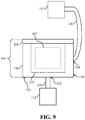
- FIG. 9 shows another non-limiting example of system 100.
- system 100 of FIG. 9 includes molten densifier source 112 in communication only with first supply conduit 120, and distinct molten densifier source 152 in communication only with second supply conduit 126.
- first location 122 of first supply conduit 120 may be form in and/or on first portion 106 of die set 104.
- first location 122 of first supply conduit 120 may be at and/or through a bottom 172 of first portion 106 of die set 104, adjacent sidewall 130.
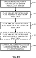
- FIG. 10 show example processes of infiltrating a porous ceramic matric composite (CMC) preform. More specifically, FIG. 10 shows a flow diagram illustrating non-limiting example processes of infiltrating and densifying a CMC preform with molten densifier material. In some cases, the processes may be used to form a CMC article from the infiltrated and densified CMC preform, as discussed herein with respect to FIGs. 1-9 .
- CMC porous ceramic matric composite
- the porous CMC preform may be positioned within an opening of a die set of an infiltration system used to perform the infiltration process.
- the CMC preform may include a plurality of ply stacks, and a plurality of voids formed between each of the ply stacks.
- Each of the plurality of ply stacks may include a predetermined, unidirectional material orientation.
- Positioning the CMC preform in the opening may also include aligning the predetermined, unidirectional material orientation of at least one of the plurality of ply stacks of the CMC preform with a second flow direction of the flowing molten densifier.
- molten densifier may flow over the CMC preform in a first flow direction. Specifically, molten densifier may flow over the CMC preform in the first flow direction to infiltrate the plurality of voids formed between each of the plurality of ply stacks of the CMC preform.
- the first flow direction may be substantially perpendicular to the predetermined, unidirectional material orientation of at least one of the plurality of ply stacks forming the CMC preform.
- Flowing the molten densifier in the first flow direction may also include supplying the molten densifier over the CMC preform in the first flow direction at a pressure equal to or above atmospheric pressure.
- molten densifier may flow over the CMC preform in a second flow direction. Specifically, molten densifier may flow over the CMC preform in the second flow direction to infiltrate the plurality of voids formed between each of the plurality of ply stacks of the CMC preform.
- the second flow direction may be distinct from the first flow direction. Additionally, the second flow direction may be substantially parallel to the predetermined, unidirectional material orientation of at least one of the plurality of ply stacks forming the CMC preform.
- Flowing the molten densifier in the second flow direction may also include supplying the molten densifier over the CMC preform in the second flow direction at a pressure greater than or above atmospheric pressure.
- molten densifier may flow over the CMC preform in a third flow direction. Specifically, molten densifier may flow over the CMC preform in the third flow direction to infiltrate the plurality of voids formed between each of the plurality of ply stacks of the CMC preform.
- the third flow direction may be distinct from the first flow direction. In non-limiting examples, the third flow direction may be identical to or distinct from the second flow direction. Additionally, the third flow direction may be substantially parallel to the predetermined, unidirectional material orientation of at least one distinct ply stack of the plurality of ply stacks forming the CMC preform.
- the distinct ply stack identified in process P4 may be different from or distinct from the ply stack of process P3.
- Flowing the molten densifier in the third flow direction may also include supplying the molten densifier over the CMC preform in the third flow direction at a pressure greater than or above atmospheric pressure.
- the velocity and/or the pressure of the molten densifier may be controlled. More specifically, the velocity and/or the pressure of the molten densifier flowing in the first direction (process P2), the second direction (process P3), and the third direction (process P4) over the CMC preform may be controlled and/or adjusted (e.g., increased, decreased, maintained) to aid in the infiltration and/or densification of the CMC preform.
- the velocity and/or the pressure of the molten densifier may be controlled using a feature positioned within and/or adjacent a supply conduit of the infiltration system flowing and/or supplying the molten densifier.
- the feature may include, but is not limited to, an enlarged portion (e.g., inlet) of the supply conduit or an adjustable valve in communication with the supply conduits.
- Technical effects of the disclosure are to provide a method and system for flowing molten densifiers parallel to predetermined, unidirectional material orientations of ply stacks for porous ceramic matrix composite (CMC) preform to improve the infiltration and/or densification of the CMC preforms.
- CMC ceramic matrix composite
- Approximating language may be applied to modify any quantitative representation that could permissibly vary without resulting in a change in the basic function to which it is related. Accordingly, a value modified by a term or terms, such as “about,” “approximately” and “substantially,” are not to be limited to the precise value specified. In at least some instances, the approximating language may correspond to the precision of an instrument for measuring the value.
- range limitations may be combined and/or interchanged, such ranges are identified and include all the sub-ranges contained therein unless context or language indicates otherwise. "Approximately” as applied to a particular value of a range applies to both values, and unless otherwise dependent on the precision of the instrument measuring the value, may indicate +/-10% of the stated value(s).
Landscapes
- Chemical & Material Sciences (AREA)
- Engineering & Computer Science (AREA)
- Ceramic Engineering (AREA)
- Materials Engineering (AREA)
- Structural Engineering (AREA)
- Organic Chemistry (AREA)
- Manufacturing & Machinery (AREA)
- Inorganic Chemistry (AREA)
- Mechanical Engineering (AREA)
- Chemical Kinetics & Catalysis (AREA)
- Physics & Mathematics (AREA)
- Plasma & Fusion (AREA)
- Manufacture Of Alloys Or Alloy Compounds (AREA)
- Devices For Post-Treatments, Processing, Supply, Discharge, And Other Processes (AREA)
Abstract
Description
- The disclosure relates generally to ceramic matrix composite (CMC) articles, and more particularly, to systems and methods for infiltrating porous CMC preforms to form CMC articles.
- Ceramic matrix composite (CMC) articles are generally considered well suited for structural components of a turbine engine due to, for example, their thermal resistance, high temperature strength, and chemical stability. However, CMC articles in a turbine engine can suffer from damage due to overstressing, excessive temperatures, improper formation, etc. One technique for addressing the damage-prone nature of the CMC articles is densification. However, conventional systems and methods for performing densification can create, for example, obstructions, cracks, and/or areas of reduced material and cause weaknesses within the CMC article. These drawbacks with conventionally densified CMC articles tend to be exacerbated the thicker the CMC article.
- Conventional techniques for casting parts (e.g., metal casting) include injection molding, high pressure die casting, and low pressure die casting. However, none of these conventional techniques for casting have been utilized to perform the densification process on CMC articles because the operational parameters for performing the techniques may increase the likelihood and/or may cause damage to the CMC articles when performing the densification process.
- A first aspect of the disclosure provides a method for infiltrating a porous ceramic matrix composite (CMC) preform. The method includes: positioning the porous CMC preform in an opening of a die set for an infiltration system, the CMC preform including: a plurality of ply stacks, each of the plurality of ply stacks including a predetermined, unidirectional material orientation, and a plurality of voids formed between each of the plurality of ply stacks; flowing a molten densifier over the porous CMC preform in a first flow direction to infiltrate the plurality of voids formed between each of the plurality of ply stacks of the CMC preform; and flowing the molten densifier over the porous CMC preform in a second flow direction, distinct from the first flow direction, to infiltrate the plurality of voids formed between each of the plurality of ply stacks of the CMC preform, wherein the second flow direction is substantially parallel to the predetermined, unidirectional material orientation of at least one ply stack of the plurality of ply stacks of the CMC preform.
- A second aspect of the disclosure provides a system including: a die set including an opening for receiving a porous ceramic matrix composite (CMC) preform; a first molten densifier supply conduit in communication with the opening of the die set in a first location of the die set, the first molten densifier supply conduit flowing a molten densifier to the opening of the die set in a first flow direction to infiltrate a plurality of voids formed between each of a plurality of ply stacks of the CMC preform; and a second molten densifier supply conduit in communication with the opening of the die set in a second location of the die set, the second molten densifier supply conduit flowing the molten densifier to the opening of the die set in a second flow direction substantially parallel to a predetermined, unidirectional material orientation of at least one ply stack of the plurality of ply stacks of the CMC preform to infiltrate the plurality of voids formed between each of the plurality of ply stacks of the CMC preform.
- The illustrative aspects of the present disclosure are designed to solve the problems herein described and/or other problems not discussed.
- These and other features of this disclosure will be more readily understood from the following detailed description of the various aspects of the disclosure taken in conjunction with the accompanying drawings that depict various embodiments of the disclosure, in which:
-
FIG. 1 shows a schematic view of a system for infiltrating a porous ceramic matrix composite (CMC) preform to form a CMC article, according to embodiments of the disclosure. -
FIG. 2 shows a front cross-sectional of the system and the CMC preform taken along line 2-2 inFIG. 1 , according to embodiments of the disclosure. -
FIG. 3 shows an enlarged view of a portion ofFIG. 2 including the system and the CMC preform, according to embodiments of the disclosure. -
FIG. 4 shows a front cross-sectional of a system and a CMC preform, according to additional embodiments of the disclosure. -
FIG. 5 shows another schematic view of a system for infiltrating a porous ceramic matrix composite (CMC) preform to form a CMC article, according to further embodiments of the disclosure. -
FIG. 6 shows an enlarged view of a portion ofFIG. 5 including the system and the CMC preform, according to embodiments of the disclosure. -
FIG. 7 shows an enlarged view of a portion ofFIG. 5 including the system and the CMC preform, according to additional embodiments of the disclosure. -
FIG. 8 shows an enlarged view of a portion ofFIG. 5 including the system and the CMC preform, according to another embodiment of the disclosure. -
FIG. 9 shows another schematic view of a system for infiltrating a porous ceramic matrix composite (CMC) preform to form a CMC article, according to further embodiments of the disclosure. -
FIG. 10 shows an illustrative flow diagram of example processes for infiltrating porous ceramic matrix composite (CMC) preforms to form CMC articles, according to embodiments of the disclosure. - It is noted that the drawings of the disclosure are not to scale. The drawings are intended to depict only typical aspects of the disclosure, and therefore should not be considered as limiting the scope of the disclosure. In the drawings, like numbering represents like elements between the drawings.
- As an initial matter, in order to clearly describe the current disclosure it will become necessary to select certain terminology when referring to and describing relevant machine components within the disclosure. When doing this, if possible, common industry terminology will be used and employed in a manner consistent with its accepted meaning. Unless otherwise stated, such terminology should be given a broad interpretation consistent with the context of the present application and the scope of the appended claims. Those of ordinary skill in the art will appreciate that often a particular component may be referred to using several different or overlapping terms. What may be described herein as being a single part may include and be referenced in another context as consisting of multiple components. Alternatively, what may be described herein as including multiple components may be referred to elsewhere as a single part.
- As indicated above, the disclosure relates generally to ceramic matrix composite (CMC) articles, and more particularly, to systems and methods for infiltrating porous CMC preforms to form CMC articles.
- These and other embodiments are discussed below with reference to
FIGs. 1-10 . However, those skilled in the art will readily appreciate that the detailed description given herein with respect to these Figures is for explanatory purposes only and should not be construed as limiting. -
FIGs. 1 and2 show various views of asystem 100 capable of infiltrating a porous ceramic matrix composite (CMC) preform 102 (hereafter, "CMC preform 102") included therein. More specifically,FIG. 1 shows a schematic view ofsystem 100 and CMC preform 102 (shown in phantom) andFIG. 2 shows a front cross-section view ofsystem 100 and CMC preform 102 taken along line 2-2 inFIG. 1 . As discussed herein,system 100 may be configured to flow a molten densifier over CMC preform 102 to infiltrate and/or densifypreform 102 to create a CMC article (not shown) that may be utilized in various systems and/or devices (e.g., hot gas path components in turbine systems). -
System 100 may include a dieset 104 configured to receivepreform 102 for infiltration, as discussed herein. In the non-limiting example, dieset 104 may include afirst portion 106 and asecond portion 108 positioned on and/or coupled tofirst portion 106. Dieset 104 may also include opening 110 formed therein. Specifically, opening 110 may be formed infirst portion 106 and/or may be formed betweenfirst portion 106 andsecond portion 108 of dieset 104. As shown inFIGs. 1 and2 , opening 110 may receive, house, and/or hold CMC preform 102 during the infiltration process performed usingsystem 100. Dieset 104 may be formed from any suitable material that may receive CMC preform 102 and withstand the pressures and/or material exposure temperatures (e.g., molten densifier) experienced when performing the infiltration process onCMC preform 102, as discussed herein. Additionally, although opening 110 of dieset 104 is shown as be substantially polygonal/quadrilateral, it is understood that opening 110 may be formed as and/or may include any configuration for receiving CMC preform 102 to perform the infiltration process. - As shown in
FIGs. 1 and2 ,system 100 may also include at least onemolten densifier source 112.Molten densifier source 112 ofsystem 100 may hold, contain, and/or store a molten densifier 118 (FIG. 2 ) that may be supplied to, flow over, and/or infiltrate CMC preform 102 during the infiltration process, as discussed herein.Molten densifier 118 may include any suitable molten source of a compound or composition capable of infiltrating CMC preform 102 and/or increasing the density of CMC preform 102 to form a CMC article (not shown). For example,molten densifier 118 may include one or more molten sources of silicon. Although a singlemolten densifier source 112 is shown inFIGs. 1 and2 , it is understood thatsystem 100 may include more sources for providingmolten densifier 118 to opening 110 of dieset 104 during the infiltration process (FIG. 9 ). - Molten
densifier source 112 may be in communication with dieset 104 via a plurality of supply conduits. For example,molten densifier source 112 may be in communication with a first molten densifier supply conduit 120 (hereafter, "first supply conduit 120").First supply conduit 120 may also be in communication with opening 110 of dieset 104 and/or may couplemolten densifier source 112 to opening 110 of dieset 104. As discussed herein,first supply conduit 120 may provide, supply, and/or flow molten densifier 118 (FIG. 2 ) to opening 110 in a first flow direction D1 (FIG. 2 ) during the infiltration process to infiltrate a plurality of voids ofCMC preform 102 formed between each of the plurality of ply stacks forming CMC preform 102 (FIG. 3 ).First supply conduit 120 may be in communication with dieset 104 in afirst location 122 of dieset 104. In the non-limiting example shown inFIGs. 1 and2 ,first location 122 offirst supply conduit 120 may be at and/or throughsecond portion 108 of dieset 104. Additionally,first location 122 offirst supply conduit 120 may also be substantially above opening 110 and/or CMC preform 102 positioned within opening 110 of dieset 104. As such, and as discussed herein,first supply conduit 120 positioned in thefirst location 122 of dieset 104 withinsystem 100 may provide, supply, and/or flowmolten densifier 118 over the top or upper-most surface of CMC preform 102, and infiltrate the voids within CMC preform 102 from top to bottom. - Briefly turning to
FIG. 2 ,first supply conduit 120 may also include aninlet 124 in direct communication with opening 110 of dieset 104. In the non-limiting example wherefirst supply conduit 120 is positioned in first location 122 (e.g., above CMC preform 102),first supply conduit 120 may flow and/or supplymolten densifier 118 to opening 110 and/or CMC preform 102 in the first flow direction (D1) at a pressure equal to (or lower than) atmospheric pressure. That is, and as shown inFIGs. 1 and2 ,molten densifier source 112 andfirst supply conduit 120 may be configured as a gravity fed system that may flowmolten densifier 118 at a pressure equal to (or lower than) atmospheric pressure. In other non-limiting examples discussed herein (FIG. 4 ),first supply conduit 120 may flow and/or supplymolten densifier 118 in the first flow direction (D1) at a pressure greater than or above atmospheric pressure. - Additionally, and as shown in
FIGs. 1 and2 ,molten densifier source 112 may be in communication with a second molten densifier supply conduit 126 (hereafter, "second supply conduit 126"). Similar tofirst supply conduit 120,second supply conduit 126 may be in communication withopening 110 of die set 104 and/or may couplemolten densifier source 112 to opening 110 of die set 104. As discussed herein,second supply conduit 126 may provide, supply, and/or flow molten densifier 118 (FIG. 2 ) to opening 110 in a second flow direction D2 (FIG. 2 ) during the infiltration process to infiltrate a plurality of voids ofCMC preform 102 formed between each of the plurality of ply stacks forming CMC preform 102 (FIG. 3 ). In the non-limiting example,second supply conduit 126 may be in communication with die set 104 in asecond location 128 of die set 104, distinct fromfirst location 122 offirst supply conduit 120. As shown inFIGs. 1 and2 ,second location 128 ofsecond supply conduit 126 may be at and/or through asidewall 130 offirst portion 106 of die set 104. Additionally,second location 128 ofsecond supply conduit 126 may also be positioned substantially adjacent to, next to, and/or horizontal from opening 110 and/orCMC preform 102 positioned within opening 110 of die set 104. As such, and as discussed herein,second supply conduit 126 positioned in thesecond location 128 of die set 104 withinsystem 100 may provide, supply, and/or flowmolten densifier 118 through a side ofCMC preform 102, and infiltrate the voids within CMC preform 102 from the side(s). - As shown in
FIG. 2 , and also similar tofirst supply conduit 120,second supply conduit 126 may also include aninlet 132 in direct communication withopening 110 of die set 104. In the non-limiting example wheresecond supply conduit 126 is positioned in second location 128 (e.g., adjacent to CMC preform 102), andmolten densifier source 112 is positioned above or elevated fromsecond location 128,second supply conduit 126 may flow and/or supplymolten densifier 118 to opening 110 and/orCMC preform 102 in the second flow direction (D2) at a pressure equal to (or lower than) atmospheric pressure (e.g., gravity fed system). In other non-limiting examples discussed herein (FIG. 4 ),second supply conduit 126 may flow and/or supplymolten densifier 118 in the second flow direction (D2) at a pressure greater than or above atmospheric pressure. - Turning to
FIG. 3 , and with continued reference toFIGs. 1 and2 , an enlarged view of a portion ofCMC preform 102 andsystem 100 ofFIG. 2 is shown. In the non-limiting example, CMC preform 102 may include a plurality ofply stacks ply stack CMC preform 102 may include a plurality of processed fibers that be formed into a solitary sheet of material, sometimes referred to as "tape." The fibers in eachply stack FIG. 3 , plystacks 134 may include fibers having a first predetermined, unidirectional material orientation that extend across and/or from left-to-right on the page when viewed in the front cross-sectional view (FIG. 2 ). Distinct fromply stacks 134, plystacks 136 may include fibers having a distinct predetermined, unidirectional material orientation that extend through and/or from in-and-out of the page when viewed in the front cross-sectional view (FIG. 2 ).CMC preform 102 may include the plurality ofply stacks stacks CMC preform 102 may be dependent on the build structure and/or the CMC article to be formed fromCMC preform 102. For example, and as shown inFIG. 3 , CMC preform 102 may includemore ply stacks 134 than plystacks 136 due to the properties (e.g., rigidity, ductility, flexibility, and so on) ofply stacks CMC preform 102. - Additionally, and as shown in
FIG. 3 , CMC preform 102 may also include a plurality ofvoids 138.Voids 138 ofCMC preform 102 may be formed between eachply stack ply stacks CMC preform 102. In order to form a CMC article fromCMC preform 102,voids 138 formed inCMC preform 102 must be substantially closed and/or filled. As discussed herein,system 100 may flow or supplymolten densifier 118 to opening 110 of die set 104 to flow through and/or betweenply stack voids 138 during infiltration process, and perform a densification process onCMC preform 102. - Briefly returning to
FIG. 2 , and as discussed herein,first supply conduit 120 is in communication withopening 110 of die set 104 in first location 122 (e.g.,second portion 108, above CMC preform 102) for flowingmolten densifier 118 overCMC preform 102. In the non-limiting example, becausefirst location 122 is above and/or overCMC preform 102 and/or opening 110 of die set 104, the first flow direction (D1) in whichfirst supply conduit 120 may flow, supply, and/or providemolten densifier 118 is substantially up-and-down on the page. Additionally, and with reference toFIG. 3 , the first flow direction (D1) ofmolten densifier 118 provided, supplied, and/or flowed overCMC preform 102 may be substantially perpendicular toCMC preform 102, and more specifically, perpendicular to the predetermined, unidirectional material orientation of at least oneply stack CMC preform 102. First flow direction (D1) ofmolten densifier 118 supplied or flowed byfirst supply conduit 120 may be substantially perpendicular to the predetermined, unidirectional material orientation of at least oneply stack CMC preform 102 as a result of, at least in part,first supply conduit 120 being positioned infirst location 122 of die set 104 and/or the orientation and/or pattern of the plurality ofply stacks CMC preform 102. - As shown in
FIG. 3 , and as discussed herein,second supply conduit 126 may be formed in die set 104 in second location 128 (e.g., sidewall 130 -FIG. 1 ) to supply or flowmolten densifier 118 to opening 110 and/or flowmolten densifier 118 overCMC preform 102 in the second flow direction (D2). In the non-limiting example, the second flow direction (D2) may be substantially parallel with the predetermined, unidirectional material orientation of at least oneply stack CMC preform 102. More specifically, the second flow direction (D2) ofmolten densifier 118 flowed, supplied, and/or provided bysecond supply conduit 126 may be substantially parallel to the predetermined, unidirectional material orientation ofply stacks 134 ofCMC preform 102. By orienting second supply conduit 126 (and/or inlet 132) to flowmolten densifier 118 in the second flow direction (D2) substantially parallel with the predetermined, unidirectional material orientation ofply stacks 134 ofCMC preform 102,molten densifier 118 may flow through, fill, and/or infiltratevoids 138 ofCMC preform 102 more efficiently and/or more effectively. Flowing molten densifier substantially parallel with the predetermined, unidirectional material orientation ofply stacks 134 ofCMC preform 102 may improve the density of the CMC article formed fromCMC preform 102, and/or reduce/eliminate the size and/or number of reduced-infiltration areas inCMC preform 102 after performing the infiltrationprocess using system 100, as discussed herein. Increasing the density, and/or reducing/eliminating the size and/or number of reduced-infiltration areas inCMC preform 102 usingsystem 100, may reduce/eliminate the amount of potential defects in the CMC article formed fromCMC preform 102 and/or may increase the operational life and/or operational efficiency of the CMC article. - Although discussed and shown herein as
second supply conduit 126 formed in die set 104 to supply or flowmolten densifier 118 in the second flow direction (D2), it is understood that CMC preform 102 may be positioned or oriented in opening 110 to alignply stacks second supply conduit 126. That is, in addition to knowing thatsecond supply conduit 126 is formed insecond location 128 of die set 104, the predetermined, unidirectional material orientation for eachply stack ply stack CMC preform 102 with the second flow direction (D2) ofmolten densifier 118 supplied bysecond supply conduit 126. As discussed herein, aligning the predetermined, unidirectional material orientation ofply stacks CMC preform 102, and/or reduce/eliminate the size and/or number of reduced-infiltration areas inCMC preform 102. -
FIG. 4 shows another non-limiting example ofsystem 100. Specifically,FIG. 4 shows a front cross-sectional view of another non-limiting example ofsystem 100. It is understood that similarly numbered and/or named components may function in a substantially similar fashion. Redundant explanation of these components has been omitted for clarity. - As shown in
FIG. 4 ,system 100 may also include a third molten densifier supply conduit 140 ("third supply conduit 140").Third supply conduit 140 may be in communication withmolten densifier source 112 for receivingmolten densifier 118 included therein. Additionally, and similar tofirst supply conduit 120 andsecond supply conduit 126,third supply conduit 140 may be in communication withopening 110 of die set 104 via aninlet 144, and/or may couplemolten densifier source 112 to opening 110 of die set 104. In the non-limiting example,third supply conduit 140 may be in communication with die set 104 in athird location 142 of die set 104, distinct fromfirst location 122 andsecond location 128. As shown inFIG. 3 ,third location 142 ofthird supply conduit 140 may be at and/or through asidewall 146 offirst portion 106 of die set 104,opposite sidewall 130. Additionally,third location 142 ofthird supply conduit 140 may also be substantially adjacent to, next to, and/or horizontal from opening 110 and/orCMC preform 102 positioned within opening 110 of die set 104. - As similarly discussed herein with respect to
FIGs. 1-3 ,third supply conduit 140 may provide, supply, and/or flowmolten densifier 118 to opening 110 in a third flow direction (D3) to infiltrate the plurality ofvoids 138 ofCMC preform 102 formed between each ply stacks 134, 136. In the non-limiting example shown inFIG. 4 , the third flow direction (D3) defined bythird supply conduit 140 may be distinct from the first flow direction (D1) defined byfirst supply conduit 120, but may be substantially similar or identical to the second flow direction (D2) defined bysecond supply conduit 126. In another non-limiting example discussed herein (FIGs. 5 and6 ), the third flow direction (D3) as defined bythird supply conduit 140 may be distinct from the first flow direction (D1) and the second flow direction (D2). As similarly discussed herein with respect tosecond supply conduit 126 ofFIGs. 1-3 , third flow direction (D3) may be substantially parallel to the predetermined, unidirectional material orientation of ply stack(s) 134, 136 ofCMC preform 102. That is, where CMC preform 102 shown inFIG. 4 includessimilar ply stack FIG. 3 ,molten densifier 118 may flow and/or be supplied in third flow direction (D3) substantially parallel with the predetermined, unidirectional material orientation ofply stacks 134 ofCMC preform 102. As a result,third supply conduit 140 may supplymolten densifier 118 to flow through, fill, and/or infiltratevoids 138 of CMC preform 102 to improve the density of the CMC article formed fromCMC preform 102, and/or reduce/eliminate the size and/or number of reduced-infiltration areas inCMC preform 102, as discussed herein. - Additionally, as shown in
FIG. 4 ,system 100 may include aplunger 148 in communication withmolten densifier source 112. That is,plunger 148 may be connected and/or interact withmolten densifier source 112 to apply a force tomolten densifier 118 included inmolten densifier source 112. By applying a force,plunger 148 may push and/or drivemolten densifier 118 throughfirst supply conduit 120,second supply conduit 126, andthird supply conduit 140 to opening 110 of die set 104 to flow throughCMC preform 102, as discussed herein. The force applied byplunger 148 may be substantially controlled and/or varied to control and/or adjust the pressure and/or velocity of themolten densifier 118 flowing through therespective supply conduits FIGs. 1-3 ,system 100 ofFIG. 4 may supplymolten densifier 118 overCMC preform 102 in the first flow direction (D1), the second flow direction (D2), and/or the third flow direction (D3) at a pressure above or greater than atmospheric pressure. -
FIGs. 5 and6 show an additional non-limiting example ofsystem 100. Specifically,FIG. 5 shows a front view of the additional non-limiting example ofsystem 100, andFIG. 6 shows an enlarged, side cross-section view of a portion ofFIG. 5 includingthird supply conduit 140 ofsystem 100, andCMC preform 102. It is understood that similarly numbered and/or named components may function in a substantially similar fashion. Redundant explanation of these components has been omitted for clarity. - As shown in
FIG. 5 ,third supply conduit 140 may be positioned in a distinct location on die set 104 than discussed herein with respect toFIG. 4 . For example,third supply conduit 140 may be in communication with die set 104 inthird location 142 of die set 104, distinct fromfirst location 122 andsecond location 128, located at and/or through asidewall 150 offirst portion 106 of die set 104.Sidewall 150 may be formed and/or positioned between opposingsidewalls third supply conduit 140 may be formed throughsidewall 150 and/or inthird location 142 of die set 104 to flow and/or supplymolten densifier 118 to opening 110 in third flow direction (D3) to infiltrate the plurality ofvoids 138 ofCMC preform 102 formed between each ply stacks 134, 136. - The non-limiting example of
system 100 shown inFIG. 5 may also include a distinct moltendensifier source 152. In the example,first supply conduit 120 may be in communication withmolten densifier source 112, whilesecond supply conduit 126 andthird supply conduit 140 may be in communication with distinct moltendensifier source 152. In one non-limiting example, distinct moltendensifier source 152 may include similarmolten densifier 118 asmolten densifier source 112. Alternatively, distinct moltendensifier source 152 may include a distinct molten densifier thanmolten densifier 118 included inmolten densifier source 112. In this non-limiting example, the distinct molten densifier included in distinct moltendensifier source 152 may include distinct material, compositional, and/or physical properties thanmolten densifier 118 to improve the infiltration and/or densification ofCMC preform 102, as discussed herein. - Turning to
FIG. 6 , and with continued reference toFIG. 5 , an enlarged, side cross-section view of a portion ofsystem 100 is shown. CMC preform 102 shown inFIG. 6 may be identical to CMC preform 102 shown and discussed herein with respect toFIG. 3 . As such, CMC preform 102 ofFIG. 6 may include a similar pattern and/or order in which plystacks FIG. 6 depicts a side view, not a front view likeFIG. 3 , the predetermined, unidirectional material orientation for eachply stack FIG. 3 . That is, and as shown inFIG. 6 , plystacks 134 may include fibers having the predetermined, unidirectional material orientation that extend through and/or in-and-out of the page when viewed in the side cross-sectional view, while ply stacks 136 include fibers having the predetermined, unidirectional material orientation that extend across and/or from left-to-right on the page when viewed in the side cross-sectional view. - As shown in
FIG. 6 , and as discussed herein,third supply conduit 140 may be formed in die set 104 in third location 142 (e.g., sidewall 146 -FIG. 4 , sidewall 150 -FIG. 5 ) to supply or flowmolten densifier 118 to opening 110 and/or flowmolten densifier 118 overCMC preform 102 in the third flow direction (D3). In the non-limiting example, the third flow direction (D3) defined bythird supply conduit 140 formed inthird location 142 and/or throughsidewall first supply conduit 120 and the second flow direction (D2) defined bysecond supply conduit 126. Also shown inFIG. 6 , the third flow direction (D3) may be substantially parallel with the predetermined, unidirectional material orientation of at least oneply stack CMC preform 102. More specifically, the third flow direction (D3) ofmolten densifier 118 flowed, supplied, and/or provided bythird supply conduit 140 may be substantially parallel to the predetermined, unidirectional material orientation ofply stacks 136 ofCMC preform 102. - By orienting third supply conduit 140 (and/or inlet 144) to flow
molten densifier 118 in the third flow direction (D3), substantially parallel with the predetermined, unidirectional material orientation ofply stacks 136 ofCMC preform 102,molten densifier 118 may flow through, fill, and/or infiltratevoids 138 ofCMC preform 102 more efficiently and/or more effectively. Flowing molten densifier substantially parallel with the predetermined, unidirectional material orientation ofply stacks 136 ofCMC preform 102 may improve the density of the CMC article formed fromCMC preform 102, and/or reduce/eliminate the size and/or number of reduced-infiltration areas inCMC preform 102 after performing the infiltrationprocess using system 100, as discussed herein. - Additionally in this non-limiting example, and as similarly discussed herein with respect to
FIG. 3 , the second flow direction (D2) (not shown) ofmolten densifier 118 flowed, supplied, and/or provided bysecond supply conduit 126 may be substantially parallel to the predetermined, unidirectional material orientation ofply stacks 134 ofCMC preform 102. As a result,second supply conduit 126 andthird supply conduit 140 ofsystem 100 each may flowmolten densifier 118 in a specific flow direction (D2, D3) that is parallel to either plystacks 134 or plystacks 136.System 100, as shown inFIG. 6 , may further improve the efficiency and/or effectiveness in which thevoids 138 formed betweenply stacks CMC preform 102 are filled, and ultimately improve the infiltration and/or densification ofCMC preform 102, as discussed herein. - At least one
supply conduit system 100 may also include afeature 154 formed on and/oradjacent inlet supply conduit molten densifier 118 is supplied and/or flowed to opening 110 of die set 104 forsystem 100. In the non-limiting example shown inFIG. 6 , feature 154 ofthird supply conduit 140 may include anenlarged portion 156 ofthird supply conduit 140 formed adjacent to and/or withininlet 144.Enlarged portion 156 may include a varying diameter or geometry that may be greater than the diameter or geometry of the remainder ofthird supply conduit 140. The inclusion ofenlarged portion 156 inthird supply conduit 140 may control, and more specifically reduce, the velocity ofmolten densifier 118 before it enters opening 110 to flow overCMC preform 102 in the third flow direction (D3). Additionally,enlarged portion 156 inthird supply conduit 140 may control, and more specifically reduce, the pressure ofmolten densifier 118 before it entersopening 110. Controlling the pressure and/or velocity of themolten densifier 118 may control and/or improve the infiltration and/or densification ofCMC preform 102, as discussed herein. - In another non-limiting example, feature 154 may include an
adjustable valve 158. As shown inFIG. 7 ,second supply conduit 126 may includeadjustable valve 158 formedadjacent inlet 132.Adjustable valve 158 may vary the diameter or geometry of a portion ofsecond supply conduit 126 positionedadjacent inlet 132. Similar to enlarged portion 156 (FIG. 6 ),adjustable valve 158 formed insecond supply conduit 126 may control or adjust (e.g., increase, decrease, maintain) the velocity and/or pressure ofmolten densifier 118 before it enters opening 110 to flow overCMC preform 102 in the second flow direction (D2). That is, by adjusting the diameter or geometry of the portion ofsecond supply conduit 126 positionedadjacent opening 132,adjustable valve 158 may control the pressure and/or velocity of themolten densifier 118. In turn, this may improve the infiltration and/or densification ofCMC preform 102, as discussed herein. - Although shown and discussed herein as only be included in second supply conduit 126 (
FIG. 7 ) or third supply conduit 140 (FIG. 6 ), it is understood that anysupply conduit system 100 may include feature 154 for controlling the velocity and/or pressure formolten densifier 118. For example,first supply conduit 120 ofsystem 100 may also include feature 154 (enlarged portion 156, adjustable valve 158) formed in and/oradjacent inlet 124 to control the velocity and/or pressure ofmolten densifier 118 supplied or flowed to opening 110 of die set 104 in the first flow direction (D1). Additionally, it is understood that any combination ofsupply conduits features 154 for controlling the velocity and/or pressure formolten densifier 118. For example, bothfirst supply conduit 120 andsecond supply conduit 126 may includefeatures 154 formed therein. -
FIG. 8 shows another non-limiting example ofsecond supply conduit 126 ofsystem 100. In the non-limiting example,second supply conduit 126 may include a splitter or partition which dividessecond supply conduit 126 into twodistinct section Second supply conduit 126 may include twodistinct sections molten densifier 118 in two distinct flow directions to infiltrateCMC preform 102. That is, and as shown inFIG. 8 , the non-limiting example ofCMC preform 102 may include plystacks CMC preform 102 shown inFIG. 8 may include plystacks FIG. 3 Additionally, the portion ofCMC preform 102 shown inFIG. 8 may include plystacks stacks CMC preform 102. Ply stacks 164 may include fibers having a first predetermined, unidirectional material orientation that extend over and/or from top-to-bottom of the page when viewed in the cross-sectional view ofFIG. 6 . Ply stacks 166 may include fibers having a distinct predetermined, unidirectional material orientation that extend through and/or in-and-out of the page when viewed in the cross-sectional view. - Each
distinct section second supply conduit 126 may providemolten densifier 118 in a flow direction that is parallel to a portion ofply stacks CMC preform 102. For example, and as similarly discussed herein with respect toFIG. 3 ,first section 160 includinginlet 132 may flow and/or supplymolten densifier 118 to opening 110 in a second direction (D2) that may be substantially parallel to the predetermined, unidirectional material orientation forply stacks 134 to fill and/or infiltratevoids 138 formed betweenply stacks 134 and plystacks 136. Additionally,second section 162 ofsecond supply conduit 126 may includeinlet 168 that flow and/or supplymolten densifier 118 in a fourth flow direction (D4). The fourth flow direction (D4) may not be exactly parallel to the predetermined, unidirectional material orientation forply stacks 164, but rather angled slightly (α) as a result of the configuration of die set 102 and/or thesecond location 128 ofsecond supply conduit 126 indie set 102. However, the fourth flow direction (D4) may be substantially close to parallel (e.g., α = 15° or less) such thatmolten densifier 118 flowing in fourth flow direction (D4) fromsecond section 162 ofsecond supply conduit 126 may more effectively and/or more efficiently flow through and/or infiltratevoids 170 formed betweenply stacks -
FIG. 9 shows another non-limiting example ofsystem 100. Specifically,system 100 ofFIG. 9 includesmolten densifier source 112 in communication only withfirst supply conduit 120, and distinct moltendensifier source 152 in communication only withsecond supply conduit 126. Additionally, and distinct from the non-limiting example shown inFIG. 1 ,first location 122 offirst supply conduit 120 may be form in and/or onfirst portion 106 of die set 104. Specifically,first location 122 offirst supply conduit 120 may be at and/or through abottom 172 offirst portion 106 of die set 104,adjacent sidewall 130. -
FIG. 10 show example processes of infiltrating a porous ceramic matric composite (CMC) preform. More specifically,FIG. 10 shows a flow diagram illustrating non-limiting example processes of infiltrating and densifying a CMC preform with molten densifier material. In some cases, the processes may be used to form a CMC article from the infiltrated and densified CMC preform, as discussed herein with respect toFIGs. 1-9 . - In process P1, the porous CMC preform may be positioned within an opening of a die set of an infiltration system used to perform the infiltration process. The CMC preform may include a plurality of ply stacks, and a plurality of voids formed between each of the ply stacks. Each of the plurality of ply stacks may include a predetermined, unidirectional material orientation. Positioning the CMC preform in the opening may also include aligning the predetermined, unidirectional material orientation of at least one of the plurality of ply stacks of the CMC preform with a second flow direction of the flowing molten densifier.
- In process P2, molten densifier may flow over the CMC preform in a first flow direction. Specifically, molten densifier may flow over the CMC preform in the first flow direction to infiltrate the plurality of voids formed between each of the plurality of ply stacks of the CMC preform. The first flow direction may be substantially perpendicular to the predetermined, unidirectional material orientation of at least one of the plurality of ply stacks forming the CMC preform. Flowing the molten densifier in the first flow direction may also include supplying the molten densifier over the CMC preform in the first flow direction at a pressure equal to or above atmospheric pressure.
- In process P3, molten densifier may flow over the CMC preform in a second flow direction. Specifically, molten densifier may flow over the CMC preform in the second flow direction to infiltrate the plurality of voids formed between each of the plurality of ply stacks of the CMC preform. The second flow direction may be distinct from the first flow direction. Additionally, the second flow direction may be substantially parallel to the predetermined, unidirectional material orientation of at least one of the plurality of ply stacks forming the CMC preform. Flowing the molten densifier in the second flow direction may also include supplying the molten densifier over the CMC preform in the second flow direction at a pressure greater than or above atmospheric pressure.
- In process P4 (shown in phantom as optional), molten densifier may flow over the CMC preform in a third flow direction. Specifically, molten densifier may flow over the CMC preform in the third flow direction to infiltrate the plurality of voids formed between each of the plurality of ply stacks of the CMC preform. The third flow direction may be distinct from the first flow direction. In non-limiting examples, the third flow direction may be identical to or distinct from the second flow direction. Additionally, the third flow direction may be substantially parallel to the predetermined, unidirectional material orientation of at least one distinct ply stack of the plurality of ply stacks forming the CMC preform. The distinct ply stack identified in process P4 may be different from or distinct from the ply stack of process P3. Flowing the molten densifier in the third flow direction may also include supplying the molten densifier over the CMC preform in the third flow direction at a pressure greater than or above atmospheric pressure.
- In process P5, the velocity and/or the pressure of the molten densifier may be controlled. More specifically, the velocity and/or the pressure of the molten densifier flowing in the first direction (process P2), the second direction (process P3), and the third direction (process P4) over the CMC preform may be controlled and/or adjusted (e.g., increased, decreased, maintained) to aid in the infiltration and/or densification of the CMC preform. The velocity and/or the pressure of the molten densifier may be controlled using a feature positioned within and/or adjacent a supply conduit of the infiltration system flowing and/or supplying the molten densifier. The feature may include, but is not limited to, an enlarged portion (e.g., inlet) of the supply conduit or an adjustable valve in communication with the supply conduits.
- Technical effects of the disclosure are to provide a method and system for flowing molten densifiers parallel to predetermined, unidirectional material orientations of ply stacks for porous ceramic matrix composite (CMC) preform to improve the infiltration and/or densification of the CMC preforms.
- The foregoing drawings show some of the processing associated according to several embodiments of this disclosure. In this regard, each drawing or block within a flow diagram of the drawings represents a process associated with embodiments of the method described. It should also be noted that in some alternative implementations, the acts noted in the drawings or blocks may occur out of the order noted in the figure or, for example, may in fact be executed substantially concurrently or in the reverse order, depending upon the act involved. Also, one of ordinary skill in the art will recognize that additional blocks that describe the processing may be added.
- The terminology used herein is for the purpose of describing particular embodiments only and is not intended to be limiting of the disclosure. As used herein, the singular forms "a", "an" and "the" are intended to include the plural forms as well, unless the context clearly indicates otherwise. It will be further understood that the terms "comprises" and/or "comprising," when used in this specification, specify the presence of stated features, integers, steps, operations, elements, and/or components, but do not preclude the presence or addition of one or more other features, integers, steps, operations, elements, components, and/or groups thereof. "Optional" or "optionally" means that the subsequently described event or circumstance may or may not occur, and that the description includes instances where the event occurs and instances where it does not.
- Approximating language, as used herein throughout the specification and claims, may be applied to modify any quantitative representation that could permissibly vary without resulting in a change in the basic function to which it is related. Accordingly, a value modified by a term or terms, such as "about," "approximately" and "substantially," are not to be limited to the precise value specified. In at least some instances, the approximating language may correspond to the precision of an instrument for measuring the value. Here and throughout the specification and claims, range limitations may be combined and/or interchanged, such ranges are identified and include all the sub-ranges contained therein unless context or language indicates otherwise. "Approximately" as applied to a particular value of a range applies to both values, and unless otherwise dependent on the precision of the instrument measuring the value, may indicate +/-10% of the stated value(s).
- The corresponding structures, materials, acts, and equivalents of all means or step plus function elements in the claims below are intended to include any structure, material, or act for performing the function in combination with other claimed elements as specifically claimed. The description of the present disclosure has been presented for purposes of illustration and description, but is not intended to be exhaustive or limited to the disclosure in the form disclosed. Many modifications and variations will be apparent to those of ordinary skill in the art without departing from the scope and spirit of the disclosure. The embodiment was chosen and described in order to best explain the principles of the disclosure and the practical application, and to enable others of ordinary skill in the art to understand the disclosure for various embodiments with various modifications as are suited to the particular use contemplated.
Claims (15)
- A method for infiltrating a porous ceramic matrix composite (CMC) preform (102), the method comprising:positioning the porous CMC preform (102) in an opening (110) of a die set (104) for an infiltration system (100), the CMC preform (102) including:a plurality of ply stacks (134, 136), each of the plurality of ply stacks (134, 136) including a predetermined, unidirectional material orientation, anda plurality of voids (138, 170) formed between each of the plurality of ply stacks (134, 136);flowing a molten densifier (118) over the porous CMC preform (102) in a first flow direction to infiltrate the plurality of voids (138, 170) formed between each of the plurality of ply stacks (134, 136) of the CMC preform (102); andflowing the molten densifier (118) over the porous CMC preform (102) in a second flow direction, distinct from the first flow direction, to infiltrate the plurality of voids (138, 170) formed between each of the plurality of ply stacks (134, 136) of the CMC preform (102),wherein the second flow direction is substantially parallel to the predetermined, unidirectional material orientation of at least one ply stack (134) of the plurality of ply stacks (134, 136) of the CMC preform (102).
- The method of claim 1, wherein the first flow direction is substantially perpendicular to the predetermined, unidirectional material orientation of the at least one ply stack (134) of the plurality of ply stacks (134, 136) of the CMC preform (102).
- The method of claim 1, wherein positioning the porous CMC preform (102) in the opening (110) of the die set (104) includes:
aligning the predetermined, unidirectional material orientation of the at least one ply stack (134) of the plurality of ply stacks (134, 136) of the CMC preform (102) with the second flow direction of the flowing molten densifier (118). - The method of claim 1, wherein flowing the molten densifier (118) over the porous CMC preform (102) in the first flow direction further includes:
supplying the molten densifier (118) over the porous CMC preform (102) in the first flow direction at a pressure equal to or above atmospheric pressure. - The method of claim 1, wherein flowing the molten densifier (118) over the porous CMC preform (102) in the second flow direction further includes:
supplying the molten densifier (118) over the porous CMC preform (102) in the second flow direction at a pressure above atmospheric pressure. - The method of claim 1, further comprising:flowing the molten densifier (118) over the porous CMC preform (102) in a third flow direction, distinct from the first flow direction, to infiltrate the plurality of voids (138, 170) formed between each of the plurality of ply stacks (134, 136) of the CMC preform (102),wherein the third flow direction is substantially parallel to the predetermined, unidirectional material orientation of at least one distinct ply stack (134) of the plurality of ply stacks (134, 136) of the CMC preform (102).
- The method of claim 6, wherein the first flow direction is substantially perpendicular to the predetermined, unidirectional material orientation of the at least one distinct ply stack (134) of the plurality of ply stacks (134, 136) of the CMC preform (102).
- The method of claim 6, wherein third flow direction is distinct from the second flow direction.
- The method of claim 6, wherein flowing the molten densifier (118) over the porous CMC preform (102) in the third flow direction further includes:
supplying the molten densifier (118) over the porous CMC preform (102) in the third flow direction at a pressure above atmospheric pressure. - The method of claim 1, further comprising at least one of:controlling a velocity of the molten densifier (118) flowing over the porous CMC preform (102) in the first flow direction, orcontrolling a velocity of the molten densifier (118) flowing over the porous CMC preform (102) in the second flow direction.
- A system (100) comprising:a die set (104) including an opening (110) for receiving a porous ceramic matrix composite (CMC) preform (102);a first molten densifier (118) supply conduit (120) in communication with the opening (110) of the die set (104) in a first location (122) of the die set (104), the first molten densifier (118) supply conduit (120) flowing a molten densifier (118) to the opening (110) of the die set (104) in a first flow direction to infiltrate a plurality of voids (138, 170) formed between each of a plurality of ply stacks (134, 136) of the CMC preform (102); anda second molten densifier (118) supply conduit (120) in communication with the opening (110) of the die set (104) in a second location (128) of the die set (104), the second molten densifier (118) supply conduit (120) flowing the molten densifier (118) to the opening (110) of the die set (104) in a second flow direction substantially parallel to a predetermined, unidirectional material orientation of at least one ply stack (134) of the plurality of ply stacks (134, 136) of the CMC preform (102) to infiltrate the plurality of voids (138, 170) formed between each of the plurality of ply stacks (134, 136) of the CMC preform (102).
- The system (100) of claim 11, further comprising:
at least one molten densifier source (112) in communication with at least one of the first molten densifier (118) supply conduit (120) or the second molten densifier (118) supply conduit (120), the at least one molten densifier source (112) storing the molten densifier (118). - The system (100) of claim 11, wherein the first molten densifier (118) supply conduit (120) includes:an inlet (132, 168) in communication with the opening (110) of the die set (104); anda feature (154) formed adjacent the inlet (132, 168), the feature (154) configured to control a velocity of the molten densifier (118) flowing in the first flow direction.
- The system (100) of claim 13, wherein the feature (154) includes one of:an adjustable valve (158), oran enlarged portion (156) of the first molten densifier (118) supply conduit (120).
- The system (100) of claim 11, wherein the first flow direction is substantially perpendicular to the predetermined, unidirectional material orientation of the at least ply stack (134) of the plurality of ply stacks (134, 136) of the CMC preform (102).
Applications Claiming Priority (1)
| Application Number | Priority Date | Filing Date | Title |
|---|---|---|---|
| US16/433,362 US11746064B2 (en) | 2019-06-06 | 2019-06-06 | Systems and methods for infiltrating porous ceramic matrix composite (CMC) preforms |
Publications (2)
| Publication Number | Publication Date |
|---|---|
| EP3747850A1 true EP3747850A1 (en) | 2020-12-09 |
| EP3747850B1 EP3747850B1 (en) | 2023-03-01 |
Family
ID=70968865
Family Applications (1)
| Application Number | Title | Priority Date | Filing Date |
|---|---|---|---|
| EP20177618.4A Active EP3747850B1 (en) | 2019-06-06 | 2020-05-29 | Method and system for infiltrating porous ceramic matrix composite (cmc) preforms |
Country Status (4)
| Country | Link |
|---|---|
| US (1) | US11746064B2 (en) |
| EP (1) | EP3747850B1 (en) |
| JP (1) | JP7608068B2 (en) |
| SG (1) | SG10202004807TA (en) |
Cited By (1)
| Publication number | Priority date | Publication date | Assignee | Title |
|---|---|---|---|---|
| EP3909759A3 (en) * | 2020-05-12 | 2022-02-23 | Goodrich Corporation | Method and system for in-plane slurry infiltration of composite preforms |
Citations (5)
| Publication number | Priority date | Publication date | Assignee | Title |
|---|---|---|---|---|
| US6767602B1 (en) * | 1996-09-30 | 2004-07-27 | Messier-Bugatti | Preparation of textile preforms for brake discs in composite material |
| US20050184413A1 (en) * | 2004-02-20 | 2005-08-25 | Forest Mark L.L. | Versatile mold flow capability in the infiltration of porous carbon preforms with pitch/thermoplastic/thermoset resins |
| EP1676824A1 (en) * | 2004-12-31 | 2006-07-05 | General Electric Company | Method of producing a ceramic matrix composite article |
| US20120156466A1 (en) * | 2009-07-17 | 2012-06-21 | Carbon Fibre Preforms Ltd | Fibre matrix and a method of making a fibre matrix |
| US20180244583A1 (en) * | 2015-10-28 | 2018-08-30 | Sgl Carbon Se | Carbon fiber-reinforced carbide-ceramic composite component |
Family Cites Families (11)
| Publication number | Priority date | Publication date | Assignee | Title |
|---|---|---|---|---|
| US5322109A (en) | 1993-05-10 | 1994-06-21 | Massachusetts Institute Of Technology, A Massachusetts Corp. | Method for pressure infiltration casting using a vent tube |
| US6641893B1 (en) * | 1997-03-14 | 2003-11-04 | Massachusetts Institute Of Technology | Functionally-graded materials and the engineering of tribological resistance at surfaces |
| WO2000076940A1 (en) | 1999-06-14 | 2000-12-21 | Sumitomo Electric Industries, Ltd. | Composite material and semiconductor device using the same |
| DE10233729B4 (en) * | 2002-07-24 | 2006-01-26 | Sgl Carbon Ag | Fiber-reinforced ceramic brake pads |
| US7223465B2 (en) | 2004-12-29 | 2007-05-29 | General Electric Company | SiC/SiC composites incorporating uncoated fibers to improve interlaminar strength |
| TWI268122B (en) | 2005-01-25 | 2006-12-01 | Au Optronics Corp | Semiconductor structure having multilayer of polysilicon and display panel applied with the same |
| WO2009013713A2 (en) | 2007-07-23 | 2009-01-29 | Element Six (Production) (Pty) Ltd | Abrasive compact |
| US9234430B2 (en) | 2013-01-15 | 2016-01-12 | General Electric Corporation | Ceramic matrix composite article and process of fabricating a ceramic matrix composite article |
| CA2920513C (en) * | 2015-02-26 | 2018-04-10 | General Electric Company | Ceramic matrix composite articles and methods for forming same |
| US10196315B2 (en) * | 2017-01-11 | 2019-02-05 | General Electric Company | Melt infiltration with SiGa and/or siln alloys |
| US11117839B2 (en) | 2019-04-24 | 2021-09-14 | General Electric Company | Densification of melt infiltrated ceramic matrix composite (CMC) articles |
-
2019
- 2019-06-06 US US16/433,362 patent/US11746064B2/en active Active
-
2020
- 2020-05-15 JP JP2020085600A patent/JP7608068B2/en active Active
- 2020-05-22 SG SG10202004807TA patent/SG10202004807TA/en unknown
- 2020-05-29 EP EP20177618.4A patent/EP3747850B1/en active Active
Patent Citations (5)
| Publication number | Priority date | Publication date | Assignee | Title |
|---|---|---|---|---|
| US6767602B1 (en) * | 1996-09-30 | 2004-07-27 | Messier-Bugatti | Preparation of textile preforms for brake discs in composite material |
| US20050184413A1 (en) * | 2004-02-20 | 2005-08-25 | Forest Mark L.L. | Versatile mold flow capability in the infiltration of porous carbon preforms with pitch/thermoplastic/thermoset resins |
| EP1676824A1 (en) * | 2004-12-31 | 2006-07-05 | General Electric Company | Method of producing a ceramic matrix composite article |
| US20120156466A1 (en) * | 2009-07-17 | 2012-06-21 | Carbon Fibre Preforms Ltd | Fibre matrix and a method of making a fibre matrix |
| US20180244583A1 (en) * | 2015-10-28 | 2018-08-30 | Sgl Carbon Se | Carbon fiber-reinforced carbide-ceramic composite component |
Cited By (3)
| Publication number | Priority date | Publication date | Assignee | Title |
|---|---|---|---|---|
| EP3909759A3 (en) * | 2020-05-12 | 2022-02-23 | Goodrich Corporation | Method and system for in-plane slurry infiltration of composite preforms |
| EP4212333A1 (en) * | 2020-05-12 | 2023-07-19 | Goodrich Corporation | Methods and systems for in-plane slurry infiltration of composite preforms |
| US12552720B2 (en) | 2020-05-12 | 2026-02-17 | Goodrich Corportion | Methods and systems for in-plane slurry infiltration of composite preforms |
Also Published As
| Publication number | Publication date |
|---|---|
| US11746064B2 (en) | 2023-09-05 |
| SG10202004807TA (en) | 2021-01-28 |
| US20200385315A1 (en) | 2020-12-10 |
| EP3747850B1 (en) | 2023-03-01 |
| JP2020199765A (en) | 2020-12-17 |
| JP7608068B2 (en) | 2025-01-06 |
Similar Documents
| Publication | Publication Date | Title |
|---|---|---|
| US20200141002A1 (en) | Monolithic gas distribution manifold and various construction techniques and use cases therefor | |
| EP3356120B1 (en) | Valve assembly and method of manufacturing a valve housing | |
| US11117839B2 (en) | Densification of melt infiltrated ceramic matrix composite (CMC) articles | |
| US20070290409A1 (en) | Rapid manufacturing of carbon nanotube composite structures | |
| EP3747850B1 (en) | Method and system for infiltrating porous ceramic matrix composite (cmc) preforms | |
| US8205476B2 (en) | Shape correcting components | |
| US20100304095A1 (en) | Method for producing highly mechanically demanded pieces and specially tools from low cost ceramics or polymers | |
| US10549520B2 (en) | Work piece having self-supporting gusset and method related thereto | |
| US11318553B2 (en) | Additive manufacturing of laminated superalloys | |
| US20180323047A1 (en) | Sputter target backing plate assemblies with cooling structures | |
| US11117838B2 (en) | Method of making a fiber preform for ceramic matrix composite (CMC) fabrication | |
| KR20130111319A (en) | Fluid control system and fluid control method | |
| EP1936006A3 (en) | Pressure swing CVI/CVD | |
| KR20160145146A (en) | Method for producing laminate, and laminate | |
| JP2024159999A (en) | Method for reinforcing layers in the stacking direction in an additive 3D printer | |
| CN108372296A (en) | A kind of method that electron beam fuse prepares functionally graded material | |
| KR20160080610A (en) | Tungsten carbide having enhanced toughness | |
| CN104736327A (en) | Method for producing a mould intended for moulding a composite part | |
| US20180207837A1 (en) | Liquid infusion molded ceramic matrix composites and methods of forming the same | |
| CN104005022B (en) | A kind of iron-based powder laser melting coating pipeline forming method | |
| Bleicher et al. | Wear reduction on cutting inserts by additional internal cooling of the cutting edge | |
| WO2002040744A1 (en) | Laser fabrication of ceramic parts | |
| EP2715784B1 (en) | Manufacturing process for a thick cubic boron nitride (cbn) layer | |
| KR20240055053A (en) | JOINING TECHNIQUES FOR COMPOSITE CERAMIC BODYS | |
| JP2010024122A (en) | Bonded silicon carbide body and method for producing the same |
Legal Events
| Date | Code | Title | Description |
|---|---|---|---|
| PUAI | Public reference made under article 153(3) epc to a published international application that has entered the european phase |
Free format text: ORIGINAL CODE: 0009012 |
|
| STAA | Information on the status of an ep patent application or granted ep patent |
Free format text: STATUS: THE APPLICATION HAS BEEN PUBLISHED |
|
| AK | Designated contracting states |
Kind code of ref document: A1 Designated state(s): AL AT BE BG CH CY CZ DE DK EE ES FI FR GB GR HR HU IE IS IT LI LT LU LV MC MK MT NL NO PL PT RO RS SE SI SK SM TR |
|
| AX | Request for extension of the european patent |
Extension state: BA ME |
|
| STAA | Information on the status of an ep patent application or granted ep patent |
Free format text: STATUS: REQUEST FOR EXAMINATION WAS MADE |
|
| 17P | Request for examination filed |
Effective date: 20210608 |
|
| RBV | Designated contracting states (corrected) |
Designated state(s): AL AT BE BG CH CY CZ DE DK EE ES FI FR GB GR HR HU IE IS IT LI LT LU LV MC MK MT NL NO PL PT RO RS SE SI SK SM TR |
|
| STAA | Information on the status of an ep patent application or granted ep patent |
Free format text: STATUS: EXAMINATION IS IN PROGRESS |
|
| 17Q | First examination report despatched |
Effective date: 20221010 |
|
| GRAP | Despatch of communication of intention to grant a patent |
Free format text: ORIGINAL CODE: EPIDOSNIGR1 |
|
| STAA | Information on the status of an ep patent application or granted ep patent |
Free format text: STATUS: GRANT OF PATENT IS INTENDED |
|
| INTG | Intention to grant announced |
Effective date: 20221114 |
|
| GRAS | Grant fee paid |
Free format text: ORIGINAL CODE: EPIDOSNIGR3 |
|
| GRAA | (expected) grant |
Free format text: ORIGINAL CODE: 0009210 |
|
| STAA | Information on the status of an ep patent application or granted ep patent |
Free format text: STATUS: THE PATENT HAS BEEN GRANTED |
|
| AK | Designated contracting states |
Kind code of ref document: B1 Designated state(s): AL AT BE BG CH CY CZ DE DK EE ES FI FR GB GR HR HU IE IS IT LI LT LU LV MC MK MT NL NO PL PT RO RS SE SI SK SM TR |
|
| REG | Reference to a national code |
Ref country code: GB Ref legal event code: FG4D |
|
| REG | Reference to a national code |
Ref country code: CH Ref legal event code: EP Ref country code: AT Ref legal event code: REF Ref document number: 1550879 Country of ref document: AT Kind code of ref document: T Effective date: 20230315 |
|
| REG | Reference to a national code |
Ref country code: DE Ref legal event code: R096 Ref document number: 602020008397 Country of ref document: DE |
|
| REG | Reference to a national code |
Ref country code: IE Ref legal event code: FG4D |
|
| REG | Reference to a national code |
Ref country code: LT Ref legal event code: MG9D |
|
| REG | Reference to a national code |
Ref country code: NL Ref legal event code: MP Effective date: 20230301 |
|
| PG25 | Lapsed in a contracting state [announced via postgrant information from national office to epo] |
Ref country code: RS Free format text: LAPSE BECAUSE OF FAILURE TO SUBMIT A TRANSLATION OF THE DESCRIPTION OR TO PAY THE FEE WITHIN THE PRESCRIBED TIME-LIMIT Effective date: 20230301 Ref country code: NO Free format text: LAPSE BECAUSE OF FAILURE TO SUBMIT A TRANSLATION OF THE DESCRIPTION OR TO PAY THE FEE WITHIN THE PRESCRIBED TIME-LIMIT Effective date: 20230601 Ref country code: LV Free format text: LAPSE BECAUSE OF FAILURE TO SUBMIT A TRANSLATION OF THE DESCRIPTION OR TO PAY THE FEE WITHIN THE PRESCRIBED TIME-LIMIT Effective date: 20230301 Ref country code: LT Free format text: LAPSE BECAUSE OF FAILURE TO SUBMIT A TRANSLATION OF THE DESCRIPTION OR TO PAY THE FEE WITHIN THE PRESCRIBED TIME-LIMIT Effective date: 20230301 Ref country code: HR Free format text: LAPSE BECAUSE OF FAILURE TO SUBMIT A TRANSLATION OF THE DESCRIPTION OR TO PAY THE FEE WITHIN THE PRESCRIBED TIME-LIMIT Effective date: 20230301 Ref country code: ES Free format text: LAPSE BECAUSE OF FAILURE TO SUBMIT A TRANSLATION OF THE DESCRIPTION OR TO PAY THE FEE WITHIN THE PRESCRIBED TIME-LIMIT Effective date: 20230301 |
|
| REG | Reference to a national code |
Ref country code: AT Ref legal event code: MK05 Ref document number: 1550879 Country of ref document: AT Kind code of ref document: T Effective date: 20230301 |
|
| PG25 | Lapsed in a contracting state [announced via postgrant information from national office to epo] |
Ref country code: SE Free format text: LAPSE BECAUSE OF FAILURE TO SUBMIT A TRANSLATION OF THE DESCRIPTION OR TO PAY THE FEE WITHIN THE PRESCRIBED TIME-LIMIT Effective date: 20230301 Ref country code: PL Free format text: LAPSE BECAUSE OF FAILURE TO SUBMIT A TRANSLATION OF THE DESCRIPTION OR TO PAY THE FEE WITHIN THE PRESCRIBED TIME-LIMIT Effective date: 20230301 Ref country code: NL Free format text: LAPSE BECAUSE OF FAILURE TO SUBMIT A TRANSLATION OF THE DESCRIPTION OR TO PAY THE FEE WITHIN THE PRESCRIBED TIME-LIMIT Effective date: 20230301 Ref country code: GR Free format text: LAPSE BECAUSE OF FAILURE TO SUBMIT A TRANSLATION OF THE DESCRIPTION OR TO PAY THE FEE WITHIN THE PRESCRIBED TIME-LIMIT Effective date: 20230602 Ref country code: FI Free format text: LAPSE BECAUSE OF FAILURE TO SUBMIT A TRANSLATION OF THE DESCRIPTION OR TO PAY THE FEE WITHIN THE PRESCRIBED TIME-LIMIT Effective date: 20230301 |
|
| PG25 | Lapsed in a contracting state [announced via postgrant information from national office to epo] |
Ref country code: SM Free format text: LAPSE BECAUSE OF FAILURE TO SUBMIT A TRANSLATION OF THE DESCRIPTION OR TO PAY THE FEE WITHIN THE PRESCRIBED TIME-LIMIT Effective date: 20230301 Ref country code: RO Free format text: LAPSE BECAUSE OF FAILURE TO SUBMIT A TRANSLATION OF THE DESCRIPTION OR TO PAY THE FEE WITHIN THE PRESCRIBED TIME-LIMIT Effective date: 20230301 Ref country code: PT Free format text: LAPSE BECAUSE OF FAILURE TO SUBMIT A TRANSLATION OF THE DESCRIPTION OR TO PAY THE FEE WITHIN THE PRESCRIBED TIME-LIMIT Effective date: 20230703 Ref country code: EE Free format text: LAPSE BECAUSE OF FAILURE TO SUBMIT A TRANSLATION OF THE DESCRIPTION OR TO PAY THE FEE WITHIN THE PRESCRIBED TIME-LIMIT Effective date: 20230301 Ref country code: CZ Free format text: LAPSE BECAUSE OF FAILURE TO SUBMIT A TRANSLATION OF THE DESCRIPTION OR TO PAY THE FEE WITHIN THE PRESCRIBED TIME-LIMIT Effective date: 20230301 Ref country code: AT Free format text: LAPSE BECAUSE OF FAILURE TO SUBMIT A TRANSLATION OF THE DESCRIPTION OR TO PAY THE FEE WITHIN THE PRESCRIBED TIME-LIMIT Effective date: 20230301 |
|
| REG | Reference to a national code |
Ref country code: DE Ref legal event code: R081 Ref document number: 602020008397 Country of ref document: DE Owner name: GENERAL ELECTRIC TECHNOLOGY GMBH, CH Free format text: FORMER OWNER: GENERAL ELECTRIC COMPANY, SCHENECTADY, NY, US |
|
| PG25 | Lapsed in a contracting state [announced via postgrant information from national office to epo] |
Ref country code: SK Free format text: LAPSE BECAUSE OF FAILURE TO SUBMIT A TRANSLATION OF THE DESCRIPTION OR TO PAY THE FEE WITHIN THE PRESCRIBED TIME-LIMIT Effective date: 20230301 Ref country code: IS Free format text: LAPSE BECAUSE OF FAILURE TO SUBMIT A TRANSLATION OF THE DESCRIPTION OR TO PAY THE FEE WITHIN THE PRESCRIBED TIME-LIMIT Effective date: 20230701 |
|
| REG | Reference to a national code |
Ref country code: DE Ref legal event code: R097 Ref document number: 602020008397 Country of ref document: DE |
|
| RAP2 | Party data changed (patent owner data changed or rights of a patent transferred) |
Owner name: GENERAL ELECTRIC TECHNOLOGY GMBH |
|
| REG | Reference to a national code |
Ref country code: CH Ref legal event code: PL |
|
| PLBE | No opposition filed within time limit |
Free format text: ORIGINAL CODE: 0009261 |
|
| STAA | Information on the status of an ep patent application or granted ep patent |
Free format text: STATUS: NO OPPOSITION FILED WITHIN TIME LIMIT |
|
| PG25 | Lapsed in a contracting state [announced via postgrant information from national office to epo] |
Ref country code: MC Free format text: LAPSE BECAUSE OF FAILURE TO SUBMIT A TRANSLATION OF THE DESCRIPTION OR TO PAY THE FEE WITHIN THE PRESCRIBED TIME-LIMIT Effective date: 20230301 |
|
| REG | Reference to a national code |
Ref country code: BE Ref legal event code: MM Effective date: 20230531 |
|
| PG25 | Lapsed in a contracting state [announced via postgrant information from national office to epo] |
Ref country code: SI Free format text: LAPSE BECAUSE OF FAILURE TO SUBMIT A TRANSLATION OF THE DESCRIPTION OR TO PAY THE FEE WITHIN THE PRESCRIBED TIME-LIMIT Effective date: 20230301 Ref country code: MC Free format text: LAPSE BECAUSE OF FAILURE TO SUBMIT A TRANSLATION OF THE DESCRIPTION OR TO PAY THE FEE WITHIN THE PRESCRIBED TIME-LIMIT Effective date: 20230301 Ref country code: LU Free format text: LAPSE BECAUSE OF NON-PAYMENT OF DUE FEES Effective date: 20230529 Ref country code: LI Free format text: LAPSE BECAUSE OF NON-PAYMENT OF DUE FEES Effective date: 20230531 Ref country code: DK Free format text: LAPSE BECAUSE OF FAILURE TO SUBMIT A TRANSLATION OF THE DESCRIPTION OR TO PAY THE FEE WITHIN THE PRESCRIBED TIME-LIMIT Effective date: 20230301 Ref country code: CH Free format text: LAPSE BECAUSE OF NON-PAYMENT OF DUE FEES Effective date: 20230531 |
|
| 26N | No opposition filed |
Effective date: 20231204 |
|
| REG | Reference to a national code |
Ref country code: IE Ref legal event code: MM4A |
|
| REG | Reference to a national code |
Ref country code: GB Ref legal event code: 732E Free format text: REGISTERED BETWEEN 20240222 AND 20240228 |
|
| PG25 | Lapsed in a contracting state [announced via postgrant information from national office to epo] |
Ref country code: IE Free format text: LAPSE BECAUSE OF NON-PAYMENT OF DUE FEES Effective date: 20230529 |
|
| PG25 | Lapsed in a contracting state [announced via postgrant information from national office to epo] |
Ref country code: IE Free format text: LAPSE BECAUSE OF NON-PAYMENT OF DUE FEES Effective date: 20230529 |
|
| PG25 | Lapsed in a contracting state [announced via postgrant information from national office to epo] |
Ref country code: IT Free format text: LAPSE BECAUSE OF FAILURE TO SUBMIT A TRANSLATION OF THE DESCRIPTION OR TO PAY THE FEE WITHIN THE PRESCRIBED TIME-LIMIT Effective date: 20230301 Ref country code: BE Free format text: LAPSE BECAUSE OF NON-PAYMENT OF DUE FEES Effective date: 20230531 |
|
| PG25 | Lapsed in a contracting state [announced via postgrant information from national office to epo] |
Ref country code: BG Free format text: LAPSE BECAUSE OF FAILURE TO SUBMIT A TRANSLATION OF THE DESCRIPTION OR TO PAY THE FEE WITHIN THE PRESCRIBED TIME-LIMIT Effective date: 20230301 |
|
| PG25 | Lapsed in a contracting state [announced via postgrant information from national office to epo] |
Ref country code: BG Free format text: LAPSE BECAUSE OF FAILURE TO SUBMIT A TRANSLATION OF THE DESCRIPTION OR TO PAY THE FEE WITHIN THE PRESCRIBED TIME-LIMIT Effective date: 20230301 |
|
| PGFP | Annual fee paid to national office [announced via postgrant information from national office to epo] |
Ref country code: DE Payment date: 20250423 Year of fee payment: 6 |
|
| PGFP | Annual fee paid to national office [announced via postgrant information from national office to epo] |
Ref country code: GB Payment date: 20250423 Year of fee payment: 6 |
|
| PGFP | Annual fee paid to national office [announced via postgrant information from national office to epo] |
Ref country code: FR Payment date: 20250423 Year of fee payment: 6 |
|
| PG25 | Lapsed in a contracting state [announced via postgrant information from national office to epo] |
Ref country code: CY Free format text: LAPSE BECAUSE OF FAILURE TO SUBMIT A TRANSLATION OF THE DESCRIPTION OR TO PAY THE FEE WITHIN THE PRESCRIBED TIME-LIMIT; INVALID AB INITIO Effective date: 20200529 |
|
| PG25 | Lapsed in a contracting state [announced via postgrant information from national office to epo] |
Ref country code: HU Free format text: LAPSE BECAUSE OF FAILURE TO SUBMIT A TRANSLATION OF THE DESCRIPTION OR TO PAY THE FEE WITHIN THE PRESCRIBED TIME-LIMIT; INVALID AB INITIO Effective date: 20200529 |
|
| PG25 | Lapsed in a contracting state [announced via postgrant information from national office to epo] |
Ref country code: TR Free format text: LAPSE BECAUSE OF FAILURE TO SUBMIT A TRANSLATION OF THE DESCRIPTION OR TO PAY THE FEE WITHIN THE PRESCRIBED TIME-LIMIT Effective date: 20230301 |