EP3747776A1 - Single track translating inlet - Google Patents
Single track translating inlet Download PDFInfo
- Publication number
- EP3747776A1 EP3747776A1 EP19216723.7A EP19216723A EP3747776A1 EP 3747776 A1 EP3747776 A1 EP 3747776A1 EP 19216723 A EP19216723 A EP 19216723A EP 3747776 A1 EP3747776 A1 EP 3747776A1
- Authority
- EP
- European Patent Office
- Prior art keywords
- rail
- track
- guide rod
- inlet assembly
- actuator
- Prior art date
- Legal status (The legal status is an assumption and is not a legal conclusion. Google has not performed a legal analysis and makes no representation as to the accuracy of the status listed.)
- Granted
Links
Images




Classifications
-
- B—PERFORMING OPERATIONS; TRANSPORTING
- B64—AIRCRAFT; AVIATION; COSMONAUTICS
- B64D—EQUIPMENT FOR FITTING IN OR TO AIRCRAFT; FLIGHT SUITS; PARACHUTES; ARRANGEMENT OR MOUNTING OF POWER PLANTS OR PROPULSION TRANSMISSIONS IN AIRCRAFT
- B64D29/00—Power-plant nacelles, fairings or cowlings
- B64D29/06—Attaching of nacelles, fairings or cowlings
-
- F—MECHANICAL ENGINEERING; LIGHTING; HEATING; WEAPONS; BLASTING
- F02—COMBUSTION ENGINES; HOT-GAS OR COMBUSTION-PRODUCT ENGINE PLANTS
- F02C—GAS-TURBINE PLANTS; AIR INTAKES FOR JET-PROPULSION PLANTS; CONTROLLING FUEL SUPPLY IN AIR-BREATHING JET-PROPULSION PLANTS
- F02C7/00—Features, components parts, details or accessories, not provided for in, or of interest apart form groups F02C1/00 - F02C6/00; Air intakes for jet-propulsion plants
- F02C7/04—Air intakes for gas-turbine plants or jet-propulsion plants
- F02C7/042—Air intakes for gas-turbine plants or jet-propulsion plants having variable geometry
-
- B—PERFORMING OPERATIONS; TRANSPORTING
- B64—AIRCRAFT; AVIATION; COSMONAUTICS
- B64D—EQUIPMENT FOR FITTING IN OR TO AIRCRAFT; FLIGHT SUITS; PARACHUTES; ARRANGEMENT OR MOUNTING OF POWER PLANTS OR PROPULSION TRANSMISSIONS IN AIRCRAFT
- B64D33/00—Arrangement in aircraft of power plant parts or auxiliaries not otherwise provided for
- B64D33/02—Arrangement in aircraft of power plant parts or auxiliaries not otherwise provided for of combustion air intakes
-
- B—PERFORMING OPERATIONS; TRANSPORTING
- B64—AIRCRAFT; AVIATION; COSMONAUTICS
- B64C—AEROPLANES; HELICOPTERS
- B64C7/00—Structures or fairings not otherwise provided for
- B64C7/02—Nacelles
-
- F—MECHANICAL ENGINEERING; LIGHTING; HEATING; WEAPONS; BLASTING
- F05—INDEXING SCHEMES RELATING TO ENGINES OR PUMPS IN VARIOUS SUBCLASSES OF CLASSES F01-F04
- F05D—INDEXING SCHEME FOR ASPECTS RELATING TO NON-POSITIVE-DISPLACEMENT MACHINES OR ENGINES, GAS-TURBINES OR JET-PROPULSION PLANTS
- F05D2250/00—Geometry
- F05D2250/40—Movement of components
- F05D2250/41—Movement of components with one degree of freedom
Definitions
- the present disclosure relates to aircraft nacelles, and more particularly to a single track translating inlet.
- a nacelle for a turbine engine typically includes an inlet, a fan cowl, a thrust reverser, and an exhaust section.
- the nacelle is typically mounted to a wing or a fuselage of an aircraft via a pylon.
- it is beneficial to modulate mass flow rate through the inlet of the nacelle. Accordingly, a shape or area defined by the inlet may be changed.
- a translating inlet assembly for a nacelle is disclosed herein.
- the translating inlet assembly may comprise a first portion and a second portion configured to translate relative to the first portion.
- a track may be located in the first portion.
- a rail may be coupled to the second portion and configured to translate along the track.
- the rail and the track may form a load bearing component configured to transfer inertial loads experienced by the second portion.
- a first actuator may be operationally coupled to the rail. The first actuator may be configured to drive the rail along the track.
- a guide rod may extend from the second portion.
- the guide rod may be located through an orifice defined by the first portion.
- the guide rod may include a stop configured to limit a translation of the guide rod.
- a second actuator may be operationally coupled to the guide rod.
- an electrical conduit may be located through a channel defined by at least one of the rail or the guide rod.
- a fluid conduit may be located through at least one of the rail or the guide rod.
- a support strut may be located within the first portion and configured to support the guide rod.
- the rail and the track may be configured to divert the inertial loads experienced by the second portion away from the first actuator.
- the nacelle may comprise a pylon and a translating inlet assembly.
- the translating inlet assembly may comprise a first portion, a second portion configured to translate relative to the first portion, a track located in the first portion and coupled to the pylon, a rail coupled to the second portion and configured to translate along the track, and a first actuator operationally coupled to the rail.
- the first actuator may be configured to drive the rail along the track.
- the rail and the track may form a load bearing component configured to transfer inertial loads experienced by the second portion to the pylon.
- the translating inlet assembly may further comprise a guide rod extending from the second portion.
- the guide rod may be located through an orifice defined by the first portion.
- a second actuator may be operationally coupled to the guide rod.
- an electrical conduit may be located through a channel defined by at least one of the rail or the guide rod.
- a fluid conduit may be located through at least one of the rail or the guide rod.
- the translating inlet assembly may further comprise a support strut located within the first portion and configured to support the guide rod.
- the rail and the track may be configured to divert the inertial loads experienced by the second portion away from the first actuator.
- the propulsion system may comprise a gas turbine engine, a pylon mounted to the gas turbine engine, and a translating inlet assembly located forward the gas turbine engine.
- the translating inlet assembly may comprise a first portion, a second portion configured to translate relative to the first portion, a track located in the first portion and coupled to the pylon, a rail coupled to the second portion and configured to translate along the track, and a first actuator operationally coupled to the rail.
- the first actuator may be configured to drive the rail along the track.
- the rail and the track may form a load bearing component configured to transfer inertial loads experienced by the second portion to the pylon.
- the translating inlet assembly may further comprise a guide rod extending from the second portion.
- the guide rod may be located through an orifice defined by the first portion.
- a second actuator may be operationally coupled to the guide rod.
- the rail and the track may be configured to divert the inertial loads experienced by the second portion away from the first actuator.
- tail refers to the direction associated with the tail (e.g., the back end) of an aircraft, or generally, to the direction of exhaust of the gas turbine.
- forward refers to the direction associated with the nose (e.g., the front end) of an aircraft, or generally, to the direction of flight or motion.
- a nacelle 100 for a propulsion system is illustrated, in accordance with various embodiments.
- Nacelle 100 may comprise a translating inlet assembly 102, a fan cowl 104, a thrust reverser 106, and an exhaust system 108.
- nacelle 100 may include a pylon 110.
- Pylon 110 may be configured to mount nacelle 100 and an engine surrounded by nacelle 100 to an aircraft structure 118, with momentary reference to FIG. 3A , such as a wing or aircraft fuselage.
- propulsion system 112 includes nacelle 100 and a gas turbine engine 114.
- Gas turbine engine 114 may be surrounded by components of nacelle 100.
- Nacelle 100 may provide smooth, aerodynamic surfaces for airflow around and into gas turbine engine 114.
- gas turbine engine 114 draws and directs a flow of air into and through propulsion system 112.
- gas turbine engine 114 is depicted as a turbofan gas turbine engine herein, it should be understood that the concepts described herein are not limited to use with turbofans as the teachings may be applied to other types of turbine engines including turbojet engines, low-bypass turbofans, high bypass turbofans, or any other gas turbine.
- nacelle 100 includes a translating inlet assembly 102.
- Translating inlet assembly 102 may include a first portion 120 and a second portion 122.
- Second portion 122 is located forward of first portion 120.
- Second portion 122 is configured to translate relative to the first portion 120.
- first portion 120 may be a stationary component, which does not translate relative to other structures (e.g., fan cowl 104, pylon 110) of nacelle 100.
- first portion 120 may be coupled forward of fan 116 of gas turbine engine 114.
- translating inlet assembly 102 is configured such that second portion 122 is located a first axial distance from first portion 120 during a first flight condition and a second axial distance from first portion 120 during a second flight condition. It is contemplated and understood that translating inlet assembly 102 may be configured to translate second portion 122 during any desired flight conditions. For example, in various embodiments, when propulsion system 112 is producing a first speed, second portion 122 may be located a first axial distance from first portion 120, and when propulsion system 112 is producing a second speed, different from the first speed, second portion 122 may be located a second, greater axial distance from first portion 120.
- translating inlet assembly 102 includes a track 126 and a rail 128.
- Track 126 may be located within first portion 120. Stated differently, first portion 120 may define a channel configured to receive to track 126.
- Track 126 is coupled to pylon 110. In various embodiments, track 126 may be integral to pylon 110. Track 126 is configured to transfer loads (e.g., inertial loads) experienced by second portion 122 to pylon 110.
- loads e.g., inertial loads
- Rail 128 is coupled to second portion 122. Rail 128 extends aftward from second portion 122. Rail 128 is configured to translate along track 126. Translation of rail 128 along track 126 drives the translation of second portion 122 relative to first portion 120. Rail 128 is coupled to second portion 122 and track 126 such that loads experienced by second portion 122 are transferred to track 126 via rail 128.
- track 126 and rail 128 form a load bearing component configured to structurally support second portion 122 and transfer loads (e.g., inertial loads) experienced by second portion 122 to pylon 110.
- translating inlet assembly 102 further includes an actuator 130.
- Actuator 130 is operationally coupled to rail 128.
- Actuator 130 is configured to drive translation of rail 128 and second portion 122.
- Actuator 130 may comprise an electric, hydraulic, pneumatic, or any other type actuator capable of driving translation of rail 128 and second portion 122.
- actuator 130 is a linear actuator.
- Actuator 130 is positioned such that actuator 130 does not experience the inertial loads applied to second portion 122. Stated differently, track 126 and rail 128 may divert the inertial loads away from actuator 130. In this regard, actuator 130 is not an inertial load bearing component. Actuator 130 may thus be smaller and/or lighter than actuators that support inertial loads.
- a controller 132 is in operable communication with actuator 130. Controller 132 may control actuation of actuator 130 and thus the translation of rail 128 and second portion 122. For example, controller 132 may send actuation commands to actuator 130. Controller 132 may be a standalone controller or controller 132 may be incorporated into an overall control for gas turbine engine 114, such as a full authority digital engine control (FADEC).
- FADEC full authority digital engine control
- translating inlet assembly 102 may further include one or more guide rods 134.
- Guide rods 134 may be coupled to second portion 122.
- Guide rods 134 extend aftward from second portion 122.
- guide rods 134 are each located through an orifice 136 defined by first portion 120.
- first portion 120 may define orifices 136 configured to receive guide rods 134.
- Guide rods 134 may help to stabilize second portion 122 during translation.
- One or more support struts 138 may be located within first portion 120. Support struts 138 provide structural support to guide rods 134. In various embodiments, support strut 138 may be part of an inlet bulkhead. In various embodiments, the interface between guide rods 134 and support struts 138 may be a sliding interface, wherein guide rods 134 translate over a smooth surface of support struts 138. In various embodiments, the interface between guide rods 134 and support struts 138 may be a geared interface, a roller system, or any other desired mechanical guidance system configured to support and guide translation of guide rods 134 along support struts 138.
- guide rods 134 may include a stop 140.
- Stop 140 is configured to generate an interference with support struts 138 and/or with first portion 120 to limit translation of second portion 122. For example, should second portion 122 become disconnected from track 126, the interference between stop 140 and support struts 138 and/or between stop 140 and first portion 120 may retain second portion 122 (i.e., prevent second portion 122 from completely separating from nacelle 100).
- rail 128 may include a track stop, similar to stop 140.
- a seal 142 may be coupled to first portion 120 or second portion 122. Seal 142 may be configured to reduce or prevent air from flowing between first portion 120 and second portion 122, when translating inlet assembly 102 is in a closed or stowed position.
- Translating second portion 122 via load bearing track 126 provides a structurally efficient load path.
- the inertial loads experienced by second portion 122 are transferred to pylon 110 through track 126, rather than through components of an actuator, which allows for lighter, less complex actuators.
- the number and size of actuators employed by translating inlet assembly 102 may be reduced, which tends to decrease weight, costs, integration risks, and opportunities for component malfunction.
- Translating inlet assembly 202 includes a first portion 220 and a second portion 222, similar to first and second portions 120, 122 in FIG. 3A .
- Second portion 222 is configured to translate relative to the first portion 220.
- a track 226 may be located within first portion 220.
- Track 226 is coupled to a pylon 210.
- Pylon 210 is mounted to an aircraft structure 218.
- Track 226 is configured to transfer loads (e.g., inertial loads) experienced by second portion 222 to pylon 210.
- a rail 228 is coupled to second portion 222.
- Rail 228 is configured to translate along track 226. Translation of rail 228 drives the translation of second portion 222 relative to first portion 220.
- Rail 228 is coupled to second portion 222 and track 226 such that loads experienced by second portion 222 are transferred to track 226 via rail 228.
- track 226 and rail 228 form a load bearing component configured to structurally support second portion 222 and transfer loads (e.g., inertial loads) experienced by second portion 222 to pylon 210.
- Translating inlet assembly 202 may further include one or more guide rods 234.
- Guide rods 234 may be coupled to second portion 222.
- Guide rods 234 extend aftward from second portion 222.
- One or more support struts 238 may be located within first portion 220.
- Support struts 238 provide structural support to guide rods 234.
- support strut 238 may be part of an inlet bulkhead.
- guide rods 234 may include a stop 240 configured to generate an interference with support struts 238 and/or with first portion 220 to limit translation of second portion 222.
- translating inlet assembly 202 further includes a first actuator 230 operationally coupled to rail 228.
- First actuator 230 is configured to drive translation of rail 228 and second portion 222.
- Translating inlet assembly 202 may further include one or more second actuators 232.
- Second actuators 232 are each operationally coupled to a guide rod 234.
- First actuator 230 is configured to drive translation of rail 228.
- Second actuators 232 are configured to drive translation of guide rods 234.
- First and second actuators 230, 232 may comprise electric, hydraulic, pneumatic, or any other type actuator capable of driving translation of rail 228 and guide rods 234.
- first actuator 230 and/or second actuators 232 may be linear actuators.
- a controller 242 is in operable communication with first and second actuators 230, 232. Controller 242 may control actuation of first and second actuators 230, 232 and thus controls the translation of rail 228, guide rods 234, and second portion 222. For example, controller 242 may send actuation commands to first and second actuators 230, 232. Controller 242 may be a standalone controller or may be incorporated into an overall control for gas turbine engine 114, such as a FADEC.
- First and second actuators 230, 232 are positioned such that they do not experience the inertial loads applied to second portion 222. Stated differently, track 226 and rail 228 may divert the inertial loads away from first and second actuators 230, 232. In this regard, first and second actuators 230, 232 are not inertial load bearing components. First and second actuators 230, 232 may thus be smaller and/or lighter, as compared to actuators that support inertial loads.
- Translating inlet assembly 302 includes a first portion 320 and a second portion 322, similar to first and second portions 120, 122 in FIG. 3A .
- Second portion 322 is configured to translate relative to the first portion 320.
- a track 326 may be located within first portion 320.
- Track 326 is coupled to a pylon 310.
- Pylon 310 is mounted to an aircraft structure 318.
- Track 326 is configured to transfer loads (e.g., inertial loads) experienced by second portion 322 to pylon 310.
- a rail 328 is coupled to second portion 322.
- Rail 328 is configured to translate along track 326. Translation of rail 328 drives the translation of second portion 322 relative to first portion 320.
- Rail 328 is coupled to second portion 322 and track 326 such that loads experienced by second portion 322 are transferred to track 326 via rail 328.
- track 326 and rail 328 form a load bearing component configured to structurally support second portion 322 and transfer loads (e.g., inertial loads) experienced by second portion 322 to pylon 310.
- Translating inlet assembly 302 may further include one or more guide rods 334.
- Guide rods 334 may be coupled to second portion 322.
- One or more support struts 338 may be located within first portion 320 to provide structural support for guide rods 334.
- support strut 338 may be part of an inlet bulkhead.
- guide rods 334 may include a stop 340 configured to generate an interference with support struts 338 and/or with first portion 320 and limit translation of second portion 322.
- translating inlet assembly 302 further includes an actuator 330 operationally coupled to rail 328.
- Actuator 330 may be similar to actuator 130, in FIG. 2A .
- a controller 332, similar to controller 132 in FIG. 2A is in operable communication with actuator 130.
- rail 328 may define one or more rail channels 346. Stated differently, rail channel(s) 346 may be formed through rail 328.
- a conduit 348 may be located within rail channel 346.
- conduit 348 may comprise a fluid conduit, through which gas or liquid may flow.
- conduit 348 may be fluidly coupled to a hot air source of an anti-ice or de-icing system. In this regard, hot air may flow into second portion 322 via conduit 348 and/or via rail channel 346.
- conduit 348 may comprise an electrical conduit configured to provide electrical power (e.g., current) to one or more electrical components of second portion 322.
- conduit 348 may be electrically coupled between a power source and a heating element located in second portion 322.
- conduit 348 may be electrically coupled between a power source and one or more sensors located in second portion 322.
- guide rod 334 may define one or more rod channels 350. Stated differently, rod channel(s) 350 may be formed through guide rod 334.
- a conduit 352 may be located within rod channel 350.
- conduit 352 may comprise a fluid conduit, through which gas or liquid may flow.
- conduit 352 may be fluidly coupled to a hot air source of an anti-ice or de-icing system. In this regard, hot air may flow into second portion 322 via conduit 352 and/or via rod channel 350.
- conduit 352 may comprise an electrical conduit configured to provide electrical power (e.g., current) to one or more electrical components of second portion 322.
- conduit 352 may be electrically coupled between a power source and a heating element located in second portion 322.
- conduit 352 may be electrically coupled between a power source and one or more sensors located in second portion 322.
- references to "one embodiment”, “an embodiment”, “various embodiments”, etc. indicate that the embodiment described may include a particular feature, structure, or characteristic, but every embodiment may not necessarily include the particular feature, structure, or characteristic. Moreover, such phrases are not necessarily referring to the same embodiment. Further, when a particular feature, structure, or characteristic is described in connection with an embodiment, it is submitted that it is within the knowledge of one skilled in the art to affect such feature, structure, or characteristic in connection with other embodiments whether or not explicitly described. After reading the description, it will be apparent to one skilled in the relevant art(s) how to implement the disclosure in alternative embodiments.
Landscapes
- Engineering & Computer Science (AREA)
- Chemical & Material Sciences (AREA)
- Combustion & Propulsion (AREA)
- Physics & Mathematics (AREA)
- Geometry (AREA)
- Mechanical Engineering (AREA)
- General Engineering & Computer Science (AREA)
- Aviation & Aerospace Engineering (AREA)
- Other Liquid Machine Or Engine Such As Wave Power Use (AREA)
Abstract
Description
- The present disclosure relates to aircraft nacelles, and more particularly to a single track translating inlet.
- A nacelle for a turbine engine typically includes an inlet, a fan cowl, a thrust reverser, and an exhaust section. The nacelle is typically mounted to a wing or a fuselage of an aircraft via a pylon. During various operating conditions and mission profiles, it is beneficial to modulate mass flow rate through the inlet of the nacelle. Accordingly, a shape or area defined by the inlet may be changed.
- A translating inlet assembly for a nacelle is disclosed herein. In accordance with various embodiments, the translating inlet assembly may comprise a first portion and a second portion configured to translate relative to the first portion. A track may be located in the first portion. A rail may be coupled to the second portion and configured to translate along the track. The rail and the track may form a load bearing component configured to transfer inertial loads experienced by the second portion. A first actuator may be operationally coupled to the rail. The first actuator may be configured to drive the rail along the track.
- In various embodiments, a guide rod may extend from the second portion. The guide rod may be located through an orifice defined by the first portion. In various embodiments, the guide rod may include a stop configured to limit a translation of the guide rod.
- In various embodiments, a second actuator may be operationally coupled to the guide rod. In various embodiments, an electrical conduit may be located through a channel defined by at least one of the rail or the guide rod.
- In various embodiments, a fluid conduit may be located through at least one of the rail or the guide rod. In various embodiments, a support strut may be located within the first portion and configured to support the guide rod.
- In various embodiments, the rail and the track may be configured to divert the inertial loads experienced by the second portion away from the first actuator.
- A nacelle is also disclosed herein. In accordance with various embodiments, the nacelle may comprise a pylon and a translating inlet assembly. The translating inlet assembly may comprise a first portion, a second portion configured to translate relative to the first portion, a track located in the first portion and coupled to the pylon, a rail coupled to the second portion and configured to translate along the track, and a first actuator operationally coupled to the rail. The first actuator may be configured to drive the rail along the track. The rail and the track may form a load bearing component configured to transfer inertial loads experienced by the second portion to the pylon.
- In various embodiments, the translating inlet assembly may further comprise a guide rod extending from the second portion. In various embodiments, the guide rod may be located through an orifice defined by the first portion.
- In various embodiments, a second actuator may be operationally coupled to the guide rod. In various embodiments, an electrical conduit may be located through a channel defined by at least one of the rail or the guide rod.
- In various embodiments, a fluid conduit may be located through at least one of the rail or the guide rod. In various embodiments, the translating inlet assembly may further comprise a support strut located within the first portion and configured to support the guide rod.
- In various embodiments, the rail and the track may be configured to divert the inertial loads experienced by the second portion away from the first actuator.
- A propulsion system is also disclosed herein. In accordance with various embodiments, the propulsion system may comprise a gas turbine engine, a pylon mounted to the gas turbine engine, and a translating inlet assembly located forward the gas turbine engine. The translating inlet assembly may comprise a first portion, a second portion configured to translate relative to the first portion, a track located in the first portion and coupled to the pylon, a rail coupled to the second portion and configured to translate along the track, and a first actuator operationally coupled to the rail. The first actuator may be configured to drive the rail along the track. The rail and the track may form a load bearing component configured to transfer inertial loads experienced by the second portion to the pylon.
- In various embodiments, the translating inlet assembly may further comprise a guide rod extending from the second portion. The guide rod may be located through an orifice defined by the first portion.
- In various embodiments, a second actuator may be operationally coupled to the guide rod. In various embodiments, the rail and the track may be configured to divert the inertial loads experienced by the second portion away from the first actuator.
- The foregoing features and elements may be combined in various combinations without exclusivity, unless expressly indicated herein otherwise. These features and elements as well as the operation of the disclosed embodiments will become more apparent in light of the following description and accompanying drawings.
- The subject matter of the present disclosure is particularly pointed out and distinctly claimed in the concluding portion of the specification. A more complete understanding of the present disclosure, however, may best be obtained by referring to the detailed description and claims when considered in connection with the drawing figures, wherein like numerals denote like elements.
-
FIG. 1A illustrates a perspective view of a nacelle, in accordance with various embodiments; -
FIG. 1B illustrates an exploded view of a propulsion system, in accordance with various embodiments; -
FIG. 2A illustrates a perspective view of a translating inlet assembly for a nacelle, in accordance with various embodiments; -
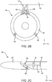
FIG. 2B illustrates an aftward-looking view of a translating inlet assembly for a nacelle, in accordance with various embodiments; -
FIG. 2C illustrates a cross-section view of a guide rod of translating inlet assembly taken along theline 2C-2C inFIG. 2A , in accordance with various embodiments; -
FIGs. 3A and 3B illustrate, respectively, a perspective view and a cross-section view of a translating inlet assembly having multiple actuators, with the cross-section taken along theline 3B-3B inFIG. 3A , in accordance with various embodiments; and -
FIGs. 4A and 4B illustrate, respectively, a perspective view and a cross-section view of a translating inlet assembly including conduit channels, with the cross-section taken along theline 4B-4B inFIG. 4A , in accordance with various embodiments; - The detailed description of various embodiments herein makes reference to the accompanying drawings, which show various embodiments by way of illustration. While these various embodiments are described in sufficient detail to enable those skilled in the art to practice the inventions, it should be understood that other embodiments may be realized and that logical, chemical and mechanical changes may be made without departing from the spirit and scope of the inventions. Thus, the detailed description herein is presented for purposes of illustration only and not of limitation. For example, the steps recited in any of the method or process descriptions may be executed in any order and are not necessarily limited to the order presented. Furthermore, any reference to singular includes plural embodiments, and any reference to more than one component or step may include a singular embodiment or step. Also, any reference to attached, fixed, connected or the like may include permanent, removable, temporary, partial, full and/or any other possible attachment option. Additionally, any reference to without contact (or similar phrases) may also include reduced contact or minimal contact.
- Surface shading and/or crosshatching lines may be used throughout the figures to denote different parts, but not necessarily to denote the same or different materials. Throughout the present disclosure, like reference numbers denote like elements. Accordingly, elements with like element numbering may be shown in the figures, but may not necessarily be repeated herein for the sake of clarity.
- As used herein, "aft" refers to the direction associated with the tail (e.g., the back end) of an aircraft, or generally, to the direction of exhaust of the gas turbine. As used herein, "forward" refers to the direction associated with the nose (e.g., the front end) of an aircraft, or generally, to the direction of flight or motion.
- Referring to
FIG. 1A , anacelle 100 for a propulsion system is illustrated, in accordance with various embodiments.Nacelle 100 may comprise a translatinginlet assembly 102, afan cowl 104, athrust reverser 106, and anexhaust system 108. In various embodiments,nacelle 100 may include apylon 110.Pylon 110 may be configured to mountnacelle 100 and an engine surrounded bynacelle 100 to anaircraft structure 118, with momentary reference toFIG. 3A , such as a wing or aircraft fuselage. - With reference to
FIG. 1B , and continuing reference toFIG. 1A , an exploded view of apropulsion system 112 is illustrated, in accordance with various embodiments. In accordance with various embodiments,propulsion system 112 includesnacelle 100 and agas turbine engine 114.Gas turbine engine 114 may be surrounded by components ofnacelle 100.Nacelle 100 may provide smooth, aerodynamic surfaces for airflow around and intogas turbine engine 114. - In operation, a
fan 116 ofgas turbine engine 114 draws and directs a flow of air into and throughpropulsion system 112. Althoughgas turbine engine 114 is depicted as a turbofan gas turbine engine herein, it should be understood that the concepts described herein are not limited to use with turbofans as the teachings may be applied to other types of turbine engines including turbojet engines, low-bypass turbofans, high bypass turbofans, or any other gas turbine. - In accordance with various embodiments,
nacelle 100 includes a translatinginlet assembly 102. Translatinginlet assembly 102 may include afirst portion 120 and asecond portion 122.Second portion 122 is located forward offirst portion 120.Second portion 122 is configured to translate relative to thefirst portion 120. In this regard,first portion 120 may be a stationary component, which does not translate relative to other structures (e.g.,fan cowl 104, pylon 110) ofnacelle 100. In various embodiments,first portion 120 may be coupled forward offan 116 ofgas turbine engine 114. - In accordance with various embodiments, translating
inlet assembly 102 is configured such thatsecond portion 122 is located a first axial distance fromfirst portion 120 during a first flight condition and a second axial distance fromfirst portion 120 during a second flight condition. It is contemplated and understood that translatinginlet assembly 102 may be configured to translatesecond portion 122 during any desired flight conditions. For example, in various embodiments, whenpropulsion system 112 is producing a first speed,second portion 122 may be located a first axial distance fromfirst portion 120, and whenpropulsion system 112 is producing a second speed, different from the first speed,second portion 122 may be located a second, greater axial distance fromfirst portion 120. - Referring to
FIGs. 2A and2B , translatinginlet assembly 102 includes atrack 126 and arail 128.Track 126 may be located withinfirst portion 120. Stated differently,first portion 120 may define a channel configured to receive to track 126.Track 126 is coupled topylon 110. In various embodiments, track 126 may be integral topylon 110.Track 126 is configured to transfer loads (e.g., inertial loads) experienced bysecond portion 122 topylon 110. -
Rail 128 is coupled tosecond portion 122.Rail 128 extends aftward fromsecond portion 122.Rail 128 is configured to translate alongtrack 126. Translation ofrail 128 alongtrack 126 drives the translation ofsecond portion 122 relative tofirst portion 120.Rail 128 is coupled tosecond portion 122 and track 126 such that loads experienced bysecond portion 122 are transferred to track 126 viarail 128. In this regard,track 126 andrail 128 form a load bearing component configured to structurally supportsecond portion 122 and transfer loads (e.g., inertial loads) experienced bysecond portion 122 topylon 110. - In accordance with various embodiments, translating
inlet assembly 102 further includes anactuator 130.Actuator 130 is operationally coupled torail 128.Actuator 130 is configured to drive translation ofrail 128 andsecond portion 122.Actuator 130 may comprise an electric, hydraulic, pneumatic, or any other type actuator capable of driving translation ofrail 128 andsecond portion 122. In various embodiments,actuator 130 is a linear actuator.Actuator 130 is positioned such thatactuator 130 does not experience the inertial loads applied tosecond portion 122. Stated differently, track 126 andrail 128 may divert the inertial loads away fromactuator 130. In this regard,actuator 130 is not an inertial load bearing component.Actuator 130 may thus be smaller and/or lighter than actuators that support inertial loads. - In various embodiments, a
controller 132 is in operable communication withactuator 130.Controller 132 may control actuation ofactuator 130 and thus the translation ofrail 128 andsecond portion 122. For example,controller 132 may send actuation commands toactuator 130.Controller 132 may be a standalone controller orcontroller 132 may be incorporated into an overall control forgas turbine engine 114, such as a full authority digital engine control (FADEC). - Referring to
FIG. 2C , and with continued reference toFIGs. 2A and2B , in various embodiments, translatinginlet assembly 102 may further include one ormore guide rods 134.Guide rods 134 may be coupled tosecond portion 122.Guide rods 134 extend aftward fromsecond portion 122. In various embodiments, guiderods 134 are each located through anorifice 136 defined byfirst portion 120. Stated differently,first portion 120 may defineorifices 136 configured to receiveguide rods 134.Guide rods 134 may help to stabilizesecond portion 122 during translation. - One or more support struts 138 may be located within
first portion 120. Support struts 138 provide structural support to guiderods 134. In various embodiments,support strut 138 may be part of an inlet bulkhead. In various embodiments, the interface betweenguide rods 134 and support struts 138 may be a sliding interface, whereinguide rods 134 translate over a smooth surface of support struts 138. In various embodiments, the interface betweenguide rods 134 and support struts 138 may be a geared interface, a roller system, or any other desired mechanical guidance system configured to support and guide translation ofguide rods 134 along support struts 138. - In various embodiments, guide
rods 134 may include astop 140. Stop 140 is configured to generate an interference with support struts 138 and/or withfirst portion 120 to limit translation ofsecond portion 122. For example, shouldsecond portion 122 become disconnected fromtrack 126, the interference betweenstop 140 and support struts 138 and/or betweenstop 140 andfirst portion 120 may retain second portion 122 (i.e., preventsecond portion 122 from completely separating from nacelle 100). In various embodiments,rail 128 may include a track stop, similar to stop 140. In various embodiments, aseal 142 may be coupled tofirst portion 120 orsecond portion 122.Seal 142 may be configured to reduce or prevent air from flowing betweenfirst portion 120 andsecond portion 122, when translatinginlet assembly 102 is in a closed or stowed position. - Translating
second portion 122 viaload bearing track 126 provides a structurally efficient load path. The inertial loads experienced bysecond portion 122 are transferred topylon 110 throughtrack 126, rather than through components of an actuator, which allows for lighter, less complex actuators. In this regard, the number and size of actuators employed by translatinginlet assembly 102 may be reduced, which tends to decrease weight, costs, integration risks, and opportunities for component malfunction. - Referring to
FIGs. 3A and 3B , a translatinginlet assembly 202 is illustrated, in accordance with various embodiments. Translatinginlet assembly 202 includes afirst portion 220 and asecond portion 222, similar to first andsecond portions FIG. 3A .Second portion 222 is configured to translate relative to thefirst portion 220. - In accordance with various embodiments, a
track 226 may be located withinfirst portion 220.Track 226 is coupled to apylon 210.Pylon 210 is mounted to anaircraft structure 218.Track 226 is configured to transfer loads (e.g., inertial loads) experienced bysecond portion 222 topylon 210. Arail 228 is coupled tosecond portion 222.Rail 228 is configured to translate alongtrack 226. Translation ofrail 228 drives the translation ofsecond portion 222 relative tofirst portion 220.Rail 228 is coupled tosecond portion 222 and track 226 such that loads experienced bysecond portion 222 are transferred to track 226 viarail 228. In this regard,track 226 andrail 228 form a load bearing component configured to structurally supportsecond portion 222 and transfer loads (e.g., inertial loads) experienced bysecond portion 222 topylon 210. - Translating
inlet assembly 202 may further include one ormore guide rods 234.Guide rods 234 may be coupled tosecond portion 222.Guide rods 234 extend aftward fromsecond portion 222. One or more support struts 238 may be located withinfirst portion 220. Support struts 238 provide structural support to guiderods 234. In various embodiments,support strut 238 may be part of an inlet bulkhead. In various embodiments, guiderods 234 may include astop 240 configured to generate an interference with support struts 238 and/or withfirst portion 220 to limit translation ofsecond portion 222. - In accordance with various embodiments, translating
inlet assembly 202 further includes afirst actuator 230 operationally coupled torail 228.First actuator 230 is configured to drive translation ofrail 228 andsecond portion 222. Translatinginlet assembly 202 may further include one or moresecond actuators 232.Second actuators 232 are each operationally coupled to aguide rod 234.First actuator 230 is configured to drive translation ofrail 228.Second actuators 232 are configured to drive translation ofguide rods 234. First andsecond actuators rail 228 and guiderods 234. In various embodiments,first actuator 230 and/orsecond actuators 232 may be linear actuators. - In various embodiments, a
controller 242 is in operable communication with first andsecond actuators Controller 242 may control actuation of first andsecond actuators rail 228, guiderods 234, andsecond portion 222. For example,controller 242 may send actuation commands to first andsecond actuators Controller 242 may be a standalone controller or may be incorporated into an overall control forgas turbine engine 114, such as a FADEC. - First and
second actuators second portion 222. Stated differently, track 226 andrail 228 may divert the inertial loads away from first andsecond actuators second actuators second actuators - Referring to
FIGs. 4A and 4B , a translatinginlet assembly 302 is illustrated, in accordance with various embodiments. Translatinginlet assembly 302 includes afirst portion 320 and asecond portion 322, similar to first andsecond portions FIG. 3A .Second portion 322 is configured to translate relative to thefirst portion 320. - In accordance with various embodiments, a
track 326 may be located withinfirst portion 320.Track 326 is coupled to apylon 310.Pylon 310 is mounted to anaircraft structure 318.Track 326 is configured to transfer loads (e.g., inertial loads) experienced bysecond portion 322 topylon 310. Arail 328 is coupled tosecond portion 322.Rail 328 is configured to translate alongtrack 326. Translation ofrail 328 drives the translation ofsecond portion 322 relative tofirst portion 320.Rail 328 is coupled tosecond portion 322 and track 326 such that loads experienced bysecond portion 322 are transferred to track 326 viarail 328. In this regard,track 326 andrail 328 form a load bearing component configured to structurally supportsecond portion 322 and transfer loads (e.g., inertial loads) experienced bysecond portion 322 topylon 310. - Translating
inlet assembly 302 may further include one ormore guide rods 334.Guide rods 334 may be coupled tosecond portion 322. One or more support struts 338 may be located withinfirst portion 320 to provide structural support forguide rods 334. In various embodiments,support strut 338 may be part of an inlet bulkhead. In various embodiments, guiderods 334 may include astop 340 configured to generate an interference with support struts 338 and/or withfirst portion 320 and limit translation ofsecond portion 322. - In accordance with various embodiments, translating
inlet assembly 302 further includes anactuator 330 operationally coupled torail 328.Actuator 330 may be similar toactuator 130, inFIG. 2A . Acontroller 332, similar tocontroller 132 inFIG. 2A , is in operable communication withactuator 130. - In various embodiments,
rail 328 may define one ormore rail channels 346. Stated differently, rail channel(s) 346 may be formed throughrail 328. In various embodiments, aconduit 348 may be located withinrail channel 346. In various embodiments,conduit 348 may comprise a fluid conduit, through which gas or liquid may flow. For example,conduit 348 may be fluidly coupled to a hot air source of an anti-ice or de-icing system. In this regard, hot air may flow intosecond portion 322 viaconduit 348 and/or viarail channel 346. In various embodiments,conduit 348 may comprise an electrical conduit configured to provide electrical power (e.g., current) to one or more electrical components ofsecond portion 322. For example,conduit 348 may be electrically coupled between a power source and a heating element located insecond portion 322. In various embodiments,conduit 348 may be electrically coupled between a power source and one or more sensors located insecond portion 322. - In various embodiments, guide
rod 334 may define one ormore rod channels 350. Stated differently, rod channel(s) 350 may be formed throughguide rod 334. In various embodiments, aconduit 352 may be located withinrod channel 350. In various embodiments,conduit 352 may comprise a fluid conduit, through which gas or liquid may flow. For example,conduit 352 may be fluidly coupled to a hot air source of an anti-ice or de-icing system. In this regard, hot air may flow intosecond portion 322 viaconduit 352 and/or viarod channel 350. In various embodiments,conduit 352 may comprise an electrical conduit configured to provide electrical power (e.g., current) to one or more electrical components ofsecond portion 322. For example,conduit 352 may be electrically coupled between a power source and a heating element located insecond portion 322. In various embodiments,conduit 352 may be electrically coupled between a power source and one or more sensors located insecond portion 322. - Benefits, other advantages, and solutions to problems have been described herein with regard to specific embodiments. Furthermore, the connecting lines shown in the various figures contained herein are intended to represent exemplary functional relationships and/or physical couplings between the various elements. It should be noted that many alternative or additional functional relationships or physical connections may be present in a practical system. However, the benefits, advantages, solutions to problems, and any elements that may cause any benefit, advantage, or solution to occur or become more pronounced are not to be construed as critical, required, or essential features or elements of the disclosure.
- The scope of the disclosure is accordingly to be limited by nothing other than the appended claims, in which reference to an element in the singular is not intended to mean "one and only one" unless explicitly so stated, but rather "one or more." It is to be understood that unless specifically stated otherwise, references to "a," "an," and/or "the" may include one or more than one and that reference to an item in the singular may also include the item in the plural. All ranges and ratio limits disclosed herein may be combined.
- Moreover, where a phrase similar to "at least one of A, B, and C" is used in the claims, it is intended that the phrase be interpreted to mean that A alone may be present in an embodiment, B alone may be present in an embodiment, C alone may be present in an embodiment, or that any combination of the elements A, B and C may be present in a single embodiment; for example, A and B, A and C, B and C, or A and B and C. Elements and steps in the figures are illustrated for simplicity and clarity and have not necessarily been rendered according to any particular sequence. For example, steps that may be performed concurrently or in different order are illustrated in the figures to help to improve understanding of embodiments of the present disclosure.
- Systems, methods and apparatus are provided herein. In the detailed description herein, references to "one embodiment", "an embodiment", "various embodiments", etc., indicate that the embodiment described may include a particular feature, structure, or characteristic, but every embodiment may not necessarily include the particular feature, structure, or characteristic. Moreover, such phrases are not necessarily referring to the same embodiment. Further, when a particular feature, structure, or characteristic is described in connection with an embodiment, it is submitted that it is within the knowledge of one skilled in the art to affect such feature, structure, or characteristic in connection with other embodiments whether or not explicitly described. After reading the description, it will be apparent to one skilled in the relevant art(s) how to implement the disclosure in alternative embodiments.
- Furthermore, no element, component, or method step in the present disclosure is intended to be dedicated to the public regardless of whether the element, component, or method step is explicitly recited in the claims. As used herein, the terms "comprises", "comprising", or any other variation thereof, are intended to cover a non-exclusive inclusion, such that a process, method, article, or apparatus that comprises a list of elements does not include only those elements but may include other elements not expressly listed or inherent to such process, method, article, or apparatus.
Claims (15)
- A translating inlet assembly for a nacelle, the translating inlet assembly comprising:a first portion;a second portion configured to translate relative to the first portion;a track located in the first portion;a rail coupled to the second portion and configured to translate along the track, wherein the rail and the track form a load bearing component configured to transfer inertial loads experienced by the second portion; anda first actuator operationally coupled to the rail, wherein the first actuator is configured to drive the rail along the track.
- The translating inlet assembly of claim 1, further comprising a guide rod extending from the second portion, wherein the guide rod is located through an orifice defined by the first portion.
- The translating inlet assembly of claim 2, wherein the guide rod includes a stop configured to limit a translation of the guide rod.
- The translating inlet assembly of claim 2 or 3, further comprising a second actuator operationally coupled to the guide rod.
- The translating inlet assembly of claim 2, 3 or 4, further comprising an electrical conduit located through a channel defined by at least one of the rail or the guide rod.
- The translating inlet assembly of any of claims 2 to 5, further comprising:a fluid conduit located through at least one of the rail or the guide rod; and/ora support strut located within the first portion and configured to support the guide rod.
- The translating inlet assembly of any preceding claim, wherein the rail and the track are configured to divert the inertial loads experienced by the second portion away from the first actuator.
- A nacelle, comprising:a pylon; anda translating inlet assembly comprising:a first portion;a second portion configured to translate relative to the first portion;a track located in the first portion and coupled to the pylon;a rail coupled to the second portion and configured to translate along the track, wherein the rail and the track form a load bearing component configured to transfer inertial loads experienced by the second portion to the pylon; anda first actuator operationally coupled to the rail, wherein the first actuator is configured to drive the rail along the track.
- The nacelle of claim 8, wherein the translating inlet assembly further comprises a guide rod extending from the second portion.
- The nacelle of claim 9, wherein the guide rod is located through an orifice defined by the first portion.
- The nacelle of claim 9 or 10, wherein:the nacelle further comprises a second actuator operationally coupled to the guide rod; and /orthe nacelle further comprises an electrical conduit located through a channel defined by at least one of the rail or the guide rod; and/orthe nacelle of further comprises a fluid conduit located through at least one of the rail or the guide rod; and/orthe translating inlet assembly further comprises a support strut located within the first portion and configured to support the guide rod.
- The nacelle of any of claims 8 to 11, wherein the rail and the track are configured to divert the inertial loads experienced by the second portion away from the first actuator.
- A propulsion system, comprising:a gas turbine engine;a pylon mounted to the gas turbine engine; anda translating inlet assembly located forward the gas turbine engine, the translating inlet assembly comprising:a first portion;a second portion configured to translate relative to the first portion;a track located in the first portion and coupled to the pylon;a rail coupled to the second portion and configured to translate along the track, wherein the rail and the track form a load bearing component configured to transfer inertial loads experienced by the second portion to the pylon; anda first actuator operationally coupled to the rail, wherein the first actuator is configured to drive the rail along the track.
- The propulsion system of claim 13, wherein the translating inlet assembly further comprises a guide rod extending from the second portion, wherein the guide rod is located through an orifice defined by the first portion.
- The propulsion system of claim 13 or 14, wherein:the propulsion system further comprises a second actuator operationally coupled to the guide rod; and/orthe rail and the track are configured to divert the inertial loads experienced by the second portion away from the first actuator.
Applications Claiming Priority (1)
| Application Number | Priority Date | Filing Date | Title |
|---|---|---|---|
| US16/431,170 US11441482B2 (en) | 2019-06-04 | 2019-06-04 | Single track translating inlet |
Publications (2)
| Publication Number | Publication Date |
|---|---|
| EP3747776A1 true EP3747776A1 (en) | 2020-12-09 |
| EP3747776B1 EP3747776B1 (en) | 2023-09-06 |
Family
ID=68917722
Family Applications (1)
| Application Number | Title | Priority Date | Filing Date |
|---|---|---|---|
| EP19216723.7A Active EP3747776B1 (en) | 2019-06-04 | 2019-12-16 | Single track translating inlet |
Country Status (2)
| Country | Link |
|---|---|
| US (1) | US11441482B2 (en) |
| EP (1) | EP3747776B1 (en) |
Families Citing this family (10)
| Publication number | Priority date | Publication date | Assignee | Title |
|---|---|---|---|---|
| FR3118481B1 (en) * | 2020-12-28 | 2023-04-21 | Safran Nacelles | Aircraft propulsion assembly air inlet comprising a member for moving a moving upstream part and method of using such an air inlet |
| US11725581B2 (en) * | 2021-06-25 | 2023-08-15 | Rohr, Inc. | Aircraft propulsion system with variable area inlet |
| US11767124B2 (en) * | 2021-09-10 | 2023-09-26 | Rohr, Inc. | Aircraft propulsion system with variable area inlet |
| US11686246B2 (en) * | 2021-10-15 | 2023-06-27 | Gulfstream Aerospace Corporation | Propulsion system for an aircraft |
| US20230249837A1 (en) * | 2022-02-08 | 2023-08-10 | Gulfstream Aerospace Corporation | Inlet arrangement, a propulsion system, and an aircraft |
| US11859545B1 (en) | 2023-01-27 | 2024-01-02 | Rohr, Inc. | Aircraft propulsion system with variable area |
| US20250333185A1 (en) * | 2024-04-30 | 2025-10-30 | Airbus Operations Sas | Method for mounting a hydrogen box in a for a hydrogen-powered aircraft |
| US12435666B1 (en) | 2024-10-09 | 2025-10-07 | General Electric Company | Turbine engine having a variable engine intake system |
| US12529335B1 (en) | 2024-10-09 | 2026-01-20 | General Electric Company | Turbine engine having a variable engine intake system |
| US12442333B1 (en) | 2024-10-09 | 2025-10-14 | General Electric Company | Turbine engine having a variable engine intake system |
Citations (13)
| Publication number | Priority date | Publication date | Assignee | Title |
|---|---|---|---|---|
| US3763874A (en) * | 1971-12-04 | 1973-10-09 | Rolls Royce | Air intake for a gas turbine engine |
| DE1751112B1 (en) * | 1967-04-05 | 1973-12-13 | Secr Defence | AIR INLET FOR GAS TURBINE JETS |
| EP0414531A2 (en) * | 1989-08-23 | 1991-02-27 | British Aerospace Public Limited Company | Self locking end stops for aircraft control surfaces |
| GB2274490A (en) * | 1993-01-26 | 1994-07-27 | Short Brothers Plc | Nacelle for an aircraft propulsive power unit |
| WO2009101273A1 (en) * | 2008-02-01 | 2009-08-20 | Aircelle | Locking system for air intake structure for turbojet engine nacelle |
| EP2199204A2 (en) * | 2008-12-17 | 2010-06-23 | Rohr, Inc. | Aircraft engine nacelle with translating inlet cowl |
| EP2222560A1 (en) * | 2007-12-26 | 2010-09-01 | Aircelle | Aircraft nacelle guidance system installation |
| EP2316727A1 (en) * | 2009-10-29 | 2011-05-04 | Asco Industries | High-lift device track |
| EP2631181A2 (en) * | 2012-02-24 | 2013-08-28 | Rohr, Inc. | Nacelle |
| US20150060607A1 (en) * | 2011-09-16 | 2015-03-05 | Tamas Havar | Lift flap bearing apparatus, lift flap assembly, airfoil and aircraft |
| US20150125270A1 (en) * | 2013-02-22 | 2015-05-07 | United Technologies Corporation | Atr guide pins for sliding nacelle |
| US20150285185A1 (en) * | 2011-10-31 | 2015-10-08 | Aircelle | Cascade-type thrust reverser with one-piece mobile cowl |
| EP2987989A1 (en) * | 2014-08-19 | 2016-02-24 | Pratt & Whitney Canada Corp. | Variable geometry inlet system |
Family Cites Families (6)
| Publication number | Priority date | Publication date | Assignee | Title |
|---|---|---|---|---|
| US3974648A (en) | 1968-08-19 | 1976-08-17 | United Technologies Corporation | Variable geometry ramjet engine |
| US5014933A (en) * | 1989-04-27 | 1991-05-14 | The Boeing Company | Translating lip aircraft cowling structure adapted for noise reduction |
| FR2906568B1 (en) * | 2006-10-02 | 2012-01-06 | Aircelle Sa | DEPOSITABLE AIR INTAKE STRUCTURE FOR TURBOJET NACELLE. |
| US7837142B2 (en) | 2006-10-12 | 2010-11-23 | Aerion Corporation | Supersonic aircraft jet engine |
| US9908633B2 (en) | 2015-03-31 | 2018-03-06 | The Boeing Company | Variable-capture supersonic inlet |
| US10399687B2 (en) * | 2015-12-03 | 2019-09-03 | The Boeing Company | Methods and apparatus to vary an air intake of aircraft engines |
-
2019
- 2019-06-04 US US16/431,170 patent/US11441482B2/en active Active
- 2019-12-16 EP EP19216723.7A patent/EP3747776B1/en active Active
Patent Citations (13)
| Publication number | Priority date | Publication date | Assignee | Title |
|---|---|---|---|---|
| DE1751112B1 (en) * | 1967-04-05 | 1973-12-13 | Secr Defence | AIR INLET FOR GAS TURBINE JETS |
| US3763874A (en) * | 1971-12-04 | 1973-10-09 | Rolls Royce | Air intake for a gas turbine engine |
| EP0414531A2 (en) * | 1989-08-23 | 1991-02-27 | British Aerospace Public Limited Company | Self locking end stops for aircraft control surfaces |
| GB2274490A (en) * | 1993-01-26 | 1994-07-27 | Short Brothers Plc | Nacelle for an aircraft propulsive power unit |
| EP2222560A1 (en) * | 2007-12-26 | 2010-09-01 | Aircelle | Aircraft nacelle guidance system installation |
| WO2009101273A1 (en) * | 2008-02-01 | 2009-08-20 | Aircelle | Locking system for air intake structure for turbojet engine nacelle |
| EP2199204A2 (en) * | 2008-12-17 | 2010-06-23 | Rohr, Inc. | Aircraft engine nacelle with translating inlet cowl |
| EP2316727A1 (en) * | 2009-10-29 | 2011-05-04 | Asco Industries | High-lift device track |
| US20150060607A1 (en) * | 2011-09-16 | 2015-03-05 | Tamas Havar | Lift flap bearing apparatus, lift flap assembly, airfoil and aircraft |
| US20150285185A1 (en) * | 2011-10-31 | 2015-10-08 | Aircelle | Cascade-type thrust reverser with one-piece mobile cowl |
| EP2631181A2 (en) * | 2012-02-24 | 2013-08-28 | Rohr, Inc. | Nacelle |
| US20150125270A1 (en) * | 2013-02-22 | 2015-05-07 | United Technologies Corporation | Atr guide pins for sliding nacelle |
| EP2987989A1 (en) * | 2014-08-19 | 2016-02-24 | Pratt & Whitney Canada Corp. | Variable geometry inlet system |
Also Published As
| Publication number | Publication date |
|---|---|
| US20200386158A1 (en) | 2020-12-10 |
| US11441482B2 (en) | 2022-09-13 |
| EP3747776B1 (en) | 2023-09-06 |
Similar Documents
| Publication | Publication Date | Title |
|---|---|---|
| EP3747776B1 (en) | Single track translating inlet | |
| US10563615B2 (en) | Gas turbine engine with thrust reverser assembly and method of operating | |
| EP2937551B1 (en) | Nacelle comprising a thrust reverser | |
| CN101939528A (en) | Area-adjustable fan nozzles with bypass flow | |
| EP1878904A2 (en) | Thrust reverser assembly for a gas turbine engine and method of operating same | |
| CN106828946B (en) | Method and device for modifying the air intake of an aircraft engine | |
| EP3452713B1 (en) | Thrust reverser assembly | |
| US10815933B2 (en) | Variable area fan nozzle actuation system | |
| EP3181948B1 (en) | Thrust reverser system with translating elements | |
| EP3347587B1 (en) | Thrust reverser assembly | |
| US10814990B2 (en) | Aircraft propulsion system with a low-fan-pressure-ratio engine in a forward over-wing flow installation, and method of installing the same | |
| EP2937550A1 (en) | Thrust reverser translating sleeve actuation system | |
| EP4230526A1 (en) | Environmental control systems | |
| EP2863040A1 (en) | Thrust reverser fan ramp partially formed on aft end of fan case | |
| US20190024609A1 (en) | Air flow deflector assembly for a thrust reverser system for reducing re-ingestion of reverse efflux air flow and method for the same | |
| US9062612B2 (en) | Actuation system for a propulsive unit of an airplane | |
| US9869275B2 (en) | Single actuator variable area fan nozzle system and method | |
| EP4471267A1 (en) | Turbine engine having a thrust reverser system | |
| EP3406527B1 (en) | Variable geometry engine inlet for high speed aircraft | |
| US9650992B2 (en) | Core cowl thrust reverser system and apparatus | |
| CN110015432A (en) | Engine nacelle for aircraft | |
| CA3064614C (en) | Translating wire harness | |
| EP4600143A1 (en) | Aircraft vertical stabilizer with moveable propulsion system(s) |
Legal Events
| Date | Code | Title | Description |
|---|---|---|---|
| PUAI | Public reference made under article 153(3) epc to a published international application that has entered the european phase |
Free format text: ORIGINAL CODE: 0009012 |
|
| STAA | Information on the status of an ep patent application or granted ep patent |
Free format text: STATUS: THE APPLICATION HAS BEEN PUBLISHED |
|
| AK | Designated contracting states |
Kind code of ref document: A1 Designated state(s): AL AT BE BG CH CY CZ DE DK EE ES FI FR GB GR HR HU IE IS IT LI LT LU LV MC MK MT NL NO PL PT RO RS SE SI SK SM TR |
|
| AX | Request for extension of the european patent |
Extension state: BA ME |
|
| STAA | Information on the status of an ep patent application or granted ep patent |
Free format text: STATUS: REQUEST FOR EXAMINATION WAS MADE |
|
| 17P | Request for examination filed |
Effective date: 20210608 |
|
| RBV | Designated contracting states (corrected) |
Designated state(s): AL AT BE BG CH CY CZ DE DK EE ES FI FR GB GR HR HU IE IS IT LI LT LU LV MC MK MT NL NO PL PT RO RS SE SI SK SM TR |
|
| STAA | Information on the status of an ep patent application or granted ep patent |
Free format text: STATUS: EXAMINATION IS IN PROGRESS |
|
| 17Q | First examination report despatched |
Effective date: 20211020 |
|
| GRAP | Despatch of communication of intention to grant a patent |
Free format text: ORIGINAL CODE: EPIDOSNIGR1 |
|
| STAA | Information on the status of an ep patent application or granted ep patent |
Free format text: STATUS: GRANT OF PATENT IS INTENDED |
|
| RIC1 | Information provided on ipc code assigned before grant |
Ipc: B64C 7/02 20060101ALN20230306BHEP Ipc: F02C 7/042 20060101ALI20230306BHEP Ipc: B64D 29/06 20060101AFI20230306BHEP |
|
| INTG | Intention to grant announced |
Effective date: 20230324 |
|
| GRAS | Grant fee paid |
Free format text: ORIGINAL CODE: EPIDOSNIGR3 |
|
| GRAA | (expected) grant |
Free format text: ORIGINAL CODE: 0009210 |
|
| STAA | Information on the status of an ep patent application or granted ep patent |
Free format text: STATUS: THE PATENT HAS BEEN GRANTED |
|
| AK | Designated contracting states |
Kind code of ref document: B1 Designated state(s): AL AT BE BG CH CY CZ DE DK EE ES FI FR GB GR HR HU IE IS IT LI LT LU LV MC MK MT NL NO PL PT RO RS SE SI SK SM TR |
|
| REG | Reference to a national code |
Ref country code: GB Ref legal event code: FG4D |
|
| REG | Reference to a national code |
Ref country code: CH Ref legal event code: EP |
|
| REG | Reference to a national code |
Ref country code: IE Ref legal event code: FG4D |
|
| REG | Reference to a national code |
Ref country code: DE Ref legal event code: R096 Ref document number: 602019036681 Country of ref document: DE |
|
| REG | Reference to a national code |
Ref country code: LT Ref legal event code: MG9D |
|
| REG | Reference to a national code |
Ref country code: NL Ref legal event code: MP Effective date: 20230906 |
|
| PG25 | Lapsed in a contracting state [announced via postgrant information from national office to epo] |
Ref country code: GR Free format text: LAPSE BECAUSE OF FAILURE TO SUBMIT A TRANSLATION OF THE DESCRIPTION OR TO PAY THE FEE WITHIN THE PRESCRIBED TIME-LIMIT Effective date: 20231207 |
|
| PG25 | Lapsed in a contracting state [announced via postgrant information from national office to epo] |
Ref country code: SE Free format text: LAPSE BECAUSE OF FAILURE TO SUBMIT A TRANSLATION OF THE DESCRIPTION OR TO PAY THE FEE WITHIN THE PRESCRIBED TIME-LIMIT Effective date: 20230906 Ref country code: RS Free format text: LAPSE BECAUSE OF FAILURE TO SUBMIT A TRANSLATION OF THE DESCRIPTION OR TO PAY THE FEE WITHIN THE PRESCRIBED TIME-LIMIT Effective date: 20230906 Ref country code: NO Free format text: LAPSE BECAUSE OF FAILURE TO SUBMIT A TRANSLATION OF THE DESCRIPTION OR TO PAY THE FEE WITHIN THE PRESCRIBED TIME-LIMIT Effective date: 20231206 Ref country code: LV Free format text: LAPSE BECAUSE OF FAILURE TO SUBMIT A TRANSLATION OF THE DESCRIPTION OR TO PAY THE FEE WITHIN THE PRESCRIBED TIME-LIMIT Effective date: 20230906 Ref country code: LT Free format text: LAPSE BECAUSE OF FAILURE TO SUBMIT A TRANSLATION OF THE DESCRIPTION OR TO PAY THE FEE WITHIN THE PRESCRIBED TIME-LIMIT Effective date: 20230906 Ref country code: HR Free format text: LAPSE BECAUSE OF FAILURE TO SUBMIT A TRANSLATION OF THE DESCRIPTION OR TO PAY THE FEE WITHIN THE PRESCRIBED TIME-LIMIT Effective date: 20230906 Ref country code: GR Free format text: LAPSE BECAUSE OF FAILURE TO SUBMIT A TRANSLATION OF THE DESCRIPTION OR TO PAY THE FEE WITHIN THE PRESCRIBED TIME-LIMIT Effective date: 20231207 Ref country code: FI Free format text: LAPSE BECAUSE OF FAILURE TO SUBMIT A TRANSLATION OF THE DESCRIPTION OR TO PAY THE FEE WITHIN THE PRESCRIBED TIME-LIMIT Effective date: 20230906 |
|
| REG | Reference to a national code |
Ref country code: AT Ref legal event code: MK05 Ref document number: 1608239 Country of ref document: AT Kind code of ref document: T Effective date: 20230906 |
|
| PG25 | Lapsed in a contracting state [announced via postgrant information from national office to epo] |
Ref country code: NL Free format text: LAPSE BECAUSE OF FAILURE TO SUBMIT A TRANSLATION OF THE DESCRIPTION OR TO PAY THE FEE WITHIN THE PRESCRIBED TIME-LIMIT Effective date: 20230906 |
|
| PG25 | Lapsed in a contracting state [announced via postgrant information from national office to epo] |
Ref country code: IS Free format text: LAPSE BECAUSE OF FAILURE TO SUBMIT A TRANSLATION OF THE DESCRIPTION OR TO PAY THE FEE WITHIN THE PRESCRIBED TIME-LIMIT Effective date: 20240106 |
|
| PG25 | Lapsed in a contracting state [announced via postgrant information from national office to epo] |
Ref country code: AT Free format text: LAPSE BECAUSE OF FAILURE TO SUBMIT A TRANSLATION OF THE DESCRIPTION OR TO PAY THE FEE WITHIN THE PRESCRIBED TIME-LIMIT Effective date: 20230906 |
|
| PG25 | Lapsed in a contracting state [announced via postgrant information from national office to epo] |
Ref country code: ES Free format text: LAPSE BECAUSE OF FAILURE TO SUBMIT A TRANSLATION OF THE DESCRIPTION OR TO PAY THE FEE WITHIN THE PRESCRIBED TIME-LIMIT Effective date: 20230906 |
|
| PG25 | Lapsed in a contracting state [announced via postgrant information from national office to epo] |
Ref country code: SM Free format text: LAPSE BECAUSE OF FAILURE TO SUBMIT A TRANSLATION OF THE DESCRIPTION OR TO PAY THE FEE WITHIN THE PRESCRIBED TIME-LIMIT Effective date: 20230906 Ref country code: RO Free format text: LAPSE BECAUSE OF FAILURE TO SUBMIT A TRANSLATION OF THE DESCRIPTION OR TO PAY THE FEE WITHIN THE PRESCRIBED TIME-LIMIT Effective date: 20230906 Ref country code: IS Free format text: LAPSE BECAUSE OF FAILURE TO SUBMIT A TRANSLATION OF THE DESCRIPTION OR TO PAY THE FEE WITHIN THE PRESCRIBED TIME-LIMIT Effective date: 20240106 Ref country code: ES Free format text: LAPSE BECAUSE OF FAILURE TO SUBMIT A TRANSLATION OF THE DESCRIPTION OR TO PAY THE FEE WITHIN THE PRESCRIBED TIME-LIMIT Effective date: 20230906 Ref country code: EE Free format text: LAPSE BECAUSE OF FAILURE TO SUBMIT A TRANSLATION OF THE DESCRIPTION OR TO PAY THE FEE WITHIN THE PRESCRIBED TIME-LIMIT Effective date: 20230906 Ref country code: CZ Free format text: LAPSE BECAUSE OF FAILURE TO SUBMIT A TRANSLATION OF THE DESCRIPTION OR TO PAY THE FEE WITHIN THE PRESCRIBED TIME-LIMIT Effective date: 20230906 Ref country code: AT Free format text: LAPSE BECAUSE OF FAILURE TO SUBMIT A TRANSLATION OF THE DESCRIPTION OR TO PAY THE FEE WITHIN THE PRESCRIBED TIME-LIMIT Effective date: 20230906 Ref country code: PT Free format text: LAPSE BECAUSE OF FAILURE TO SUBMIT A TRANSLATION OF THE DESCRIPTION OR TO PAY THE FEE WITHIN THE PRESCRIBED TIME-LIMIT Effective date: 20240108 Ref country code: SK Free format text: LAPSE BECAUSE OF FAILURE TO SUBMIT A TRANSLATION OF THE DESCRIPTION OR TO PAY THE FEE WITHIN THE PRESCRIBED TIME-LIMIT Effective date: 20230906 |
|
| PG25 | Lapsed in a contracting state [announced via postgrant information from national office to epo] |
Ref country code: PL Free format text: LAPSE BECAUSE OF FAILURE TO SUBMIT A TRANSLATION OF THE DESCRIPTION OR TO PAY THE FEE WITHIN THE PRESCRIBED TIME-LIMIT Effective date: 20230906 Ref country code: IT Free format text: LAPSE BECAUSE OF FAILURE TO SUBMIT A TRANSLATION OF THE DESCRIPTION OR TO PAY THE FEE WITHIN THE PRESCRIBED TIME-LIMIT Effective date: 20230906 |
|
| REG | Reference to a national code |
Ref country code: DE Ref legal event code: R097 Ref document number: 602019036681 Country of ref document: DE |
|
| PG25 | Lapsed in a contracting state [announced via postgrant information from national office to epo] |
Ref country code: DK Free format text: LAPSE BECAUSE OF FAILURE TO SUBMIT A TRANSLATION OF THE DESCRIPTION OR TO PAY THE FEE WITHIN THE PRESCRIBED TIME-LIMIT Effective date: 20230906 |
|
| PLBE | No opposition filed within time limit |
Free format text: ORIGINAL CODE: 0009261 |
|
| STAA | Information on the status of an ep patent application or granted ep patent |
Free format text: STATUS: NO OPPOSITION FILED WITHIN TIME LIMIT |
|
| PG25 | Lapsed in a contracting state [announced via postgrant information from national office to epo] |
Ref country code: DK Free format text: LAPSE BECAUSE OF FAILURE TO SUBMIT A TRANSLATION OF THE DESCRIPTION OR TO PAY THE FEE WITHIN THE PRESCRIBED TIME-LIMIT Effective date: 20230906 Ref country code: SI Free format text: LAPSE BECAUSE OF FAILURE TO SUBMIT A TRANSLATION OF THE DESCRIPTION OR TO PAY THE FEE WITHIN THE PRESCRIBED TIME-LIMIT Effective date: 20230906 |
|
| REG | Reference to a national code |
Ref country code: CH Ref legal event code: PL |
|
| 26N | No opposition filed |
Effective date: 20240607 |
|
| PG25 | Lapsed in a contracting state [announced via postgrant information from national office to epo] |
Ref country code: LU Free format text: LAPSE BECAUSE OF NON-PAYMENT OF DUE FEES Effective date: 20231216 |
|
| PG25 | Lapsed in a contracting state [announced via postgrant information from national office to epo] |
Ref country code: MC Free format text: LAPSE BECAUSE OF FAILURE TO SUBMIT A TRANSLATION OF THE DESCRIPTION OR TO PAY THE FEE WITHIN THE PRESCRIBED TIME-LIMIT Effective date: 20230906 |
|
| REG | Reference to a national code |
Ref country code: BE Ref legal event code: MM Effective date: 20231231 |
|
| PG25 | Lapsed in a contracting state [announced via postgrant information from national office to epo] |
Ref country code: MC Free format text: LAPSE BECAUSE OF FAILURE TO SUBMIT A TRANSLATION OF THE DESCRIPTION OR TO PAY THE FEE WITHIN THE PRESCRIBED TIME-LIMIT Effective date: 20230906 Ref country code: LU Free format text: LAPSE BECAUSE OF NON-PAYMENT OF DUE FEES Effective date: 20231216 |
|
| REG | Reference to a national code |
Ref country code: IE Ref legal event code: MM4A |
|
| PG25 | Lapsed in a contracting state [announced via postgrant information from national office to epo] |
Ref country code: IE Free format text: LAPSE BECAUSE OF NON-PAYMENT OF DUE FEES Effective date: 20231216 |
|
| PG25 | Lapsed in a contracting state [announced via postgrant information from national office to epo] |
Ref country code: BE Free format text: LAPSE BECAUSE OF NON-PAYMENT OF DUE FEES Effective date: 20231231 |
|
| PG25 | Lapsed in a contracting state [announced via postgrant information from national office to epo] |
Ref country code: CH Free format text: LAPSE BECAUSE OF NON-PAYMENT OF DUE FEES Effective date: 20231231 |
|
| PG25 | Lapsed in a contracting state [announced via postgrant information from national office to epo] |
Ref country code: IE Free format text: LAPSE BECAUSE OF NON-PAYMENT OF DUE FEES Effective date: 20231216 Ref country code: CH Free format text: LAPSE BECAUSE OF NON-PAYMENT OF DUE FEES Effective date: 20231231 Ref country code: BE Free format text: LAPSE BECAUSE OF NON-PAYMENT OF DUE FEES Effective date: 20231231 |
|
| PG25 | Lapsed in a contracting state [announced via postgrant information from national office to epo] |
Ref country code: BG Free format text: LAPSE BECAUSE OF FAILURE TO SUBMIT A TRANSLATION OF THE DESCRIPTION OR TO PAY THE FEE WITHIN THE PRESCRIBED TIME-LIMIT Effective date: 20230906 |
|
| PG25 | Lapsed in a contracting state [announced via postgrant information from national office to epo] |
Ref country code: BG Free format text: LAPSE BECAUSE OF FAILURE TO SUBMIT A TRANSLATION OF THE DESCRIPTION OR TO PAY THE FEE WITHIN THE PRESCRIBED TIME-LIMIT Effective date: 20230906 |
|
| PG25 | Lapsed in a contracting state [announced via postgrant information from national office to epo] |
Ref country code: CY Free format text: LAPSE BECAUSE OF FAILURE TO SUBMIT A TRANSLATION OF THE DESCRIPTION OR TO PAY THE FEE WITHIN THE PRESCRIBED TIME-LIMIT; INVALID AB INITIO Effective date: 20191216 |
|
| PG25 | Lapsed in a contracting state [announced via postgrant information from national office to epo] |
Ref country code: HU Free format text: LAPSE BECAUSE OF FAILURE TO SUBMIT A TRANSLATION OF THE DESCRIPTION OR TO PAY THE FEE WITHIN THE PRESCRIBED TIME-LIMIT; INVALID AB INITIO Effective date: 20191216 |
|
| PG25 | Lapsed in a contracting state [announced via postgrant information from national office to epo] |
Ref country code: TR Free format text: LAPSE BECAUSE OF FAILURE TO SUBMIT A TRANSLATION OF THE DESCRIPTION OR TO PAY THE FEE WITHIN THE PRESCRIBED TIME-LIMIT Effective date: 20230906 |
|
| PGFP | Annual fee paid to national office [announced via postgrant information from national office to epo] |
Ref country code: DE Payment date: 20251126 Year of fee payment: 7 |
|
| PGFP | Annual fee paid to national office [announced via postgrant information from national office to epo] |
Ref country code: GB Payment date: 20251119 Year of fee payment: 7 |
|
| PGFP | Annual fee paid to national office [announced via postgrant information from national office to epo] |
Ref country code: FR Payment date: 20251120 Year of fee payment: 7 |
|
| P01 | Opt-out of the competence of the unified patent court (upc) registered |
Free format text: CASE NUMBER: UPC_APP_0018894_3747776/2025 Effective date: 20251222 |