EP3747765B1 - Self-lubricated electrically conductive bushing - Google Patents
Self-lubricated electrically conductive bushing Download PDFInfo
- Publication number
- EP3747765B1 EP3747765B1 EP20178483.2A EP20178483A EP3747765B1 EP 3747765 B1 EP3747765 B1 EP 3747765B1 EP 20178483 A EP20178483 A EP 20178483A EP 3747765 B1 EP3747765 B1 EP 3747765B1
- Authority
- EP
- European Patent Office
- Prior art keywords
- axial
- self
- cylindrical
- liner
- lubricating liner
- Prior art date
- Legal status (The legal status is an assumption and is not a legal conclusion. Google has not performed a legal analysis and makes no representation as to the accuracy of the status listed.)
- Active
Links
Images




Classifications
-
- F—MECHANICAL ENGINEERING; LIGHTING; HEATING; WEAPONS; BLASTING
- F16—ENGINEERING ELEMENTS AND UNITS; GENERAL MEASURES FOR PRODUCING AND MAINTAINING EFFECTIVE FUNCTIONING OF MACHINES OR INSTALLATIONS; THERMAL INSULATION IN GENERAL
- F16C—SHAFTS; FLEXIBLE SHAFTS; ELEMENTS OR CRANKSHAFT MECHANISMS; ROTARY BODIES OTHER THAN GEARING ELEMENTS; BEARINGS
- F16C17/00—Sliding-contact bearings for exclusively rotary movement
- F16C17/10—Sliding-contact bearings for exclusively rotary movement for both radial and axial load
- F16C17/102—Sliding-contact bearings for exclusively rotary movement for both radial and axial load with grooves in the bearing surface to generate hydrodynamic pressure
- F16C17/107—Sliding-contact bearings for exclusively rotary movement for both radial and axial load with grooves in the bearing surface to generate hydrodynamic pressure with at least one surface for radial load and at least one surface for axial load
-
- F—MECHANICAL ENGINEERING; LIGHTING; HEATING; WEAPONS; BLASTING
- F16—ENGINEERING ELEMENTS AND UNITS; GENERAL MEASURES FOR PRODUCING AND MAINTAINING EFFECTIVE FUNCTIONING OF MACHINES OR INSTALLATIONS; THERMAL INSULATION IN GENERAL
- F16C—SHAFTS; FLEXIBLE SHAFTS; ELEMENTS OR CRANKSHAFT MECHANISMS; ROTARY BODIES OTHER THAN GEARING ELEMENTS; BEARINGS
- F16C33/00—Parts of bearings; Special methods for making bearings or parts thereof
- F16C33/02—Parts of sliding-contact bearings
- F16C33/04—Brasses; Bushes; Linings
- F16C33/06—Sliding surface mainly made of metal
-
- B—PERFORMING OPERATIONS; TRANSPORTING
- B64—AIRCRAFT; AVIATION; COSMONAUTICS
- B64C—AEROPLANES; HELICOPTERS
- B64C25/00—Alighting gear
- B64C25/02—Undercarriages
- B64C25/08—Undercarriages non-fixed, e.g. jettisonable
-
- B—PERFORMING OPERATIONS; TRANSPORTING
- B64—AIRCRAFT; AVIATION; COSMONAUTICS
- B64D—EQUIPMENT FOR FITTING IN OR TO AIRCRAFT; FLIGHT SUITS; PARACHUTES; ARRANGEMENT OR MOUNTING OF POWER PLANTS OR PROPULSION TRANSMISSIONS IN AIRCRAFT
- B64D45/00—Aircraft indicators or protectors not otherwise provided for
- B64D45/02—Lightning protectors; Static dischargers
-
- F—MECHANICAL ENGINEERING; LIGHTING; HEATING; WEAPONS; BLASTING
- F16—ENGINEERING ELEMENTS AND UNITS; GENERAL MEASURES FOR PRODUCING AND MAINTAINING EFFECTIVE FUNCTIONING OF MACHINES OR INSTALLATIONS; THERMAL INSULATION IN GENERAL
- F16C—SHAFTS; FLEXIBLE SHAFTS; ELEMENTS OR CRANKSHAFT MECHANISMS; ROTARY BODIES OTHER THAN GEARING ELEMENTS; BEARINGS
- F16C33/00—Parts of bearings; Special methods for making bearings or parts thereof
- F16C33/02—Parts of sliding-contact bearings
- F16C33/04—Brasses; Bushes; Linings
- F16C33/06—Sliding surface mainly made of metal
- F16C33/10—Construction relative to lubrication
-
- F—MECHANICAL ENGINEERING; LIGHTING; HEATING; WEAPONS; BLASTING
- F16—ENGINEERING ELEMENTS AND UNITS; GENERAL MEASURES FOR PRODUCING AND MAINTAINING EFFECTIVE FUNCTIONING OF MACHINES OR INSTALLATIONS; THERMAL INSULATION IN GENERAL
- F16C—SHAFTS; FLEXIBLE SHAFTS; ELEMENTS OR CRANKSHAFT MECHANISMS; ROTARY BODIES OTHER THAN GEARING ELEMENTS; BEARINGS
- F16C33/00—Parts of bearings; Special methods for making bearings or parts thereof
- F16C33/02—Parts of sliding-contact bearings
- F16C33/04—Brasses; Bushes; Linings
- F16C33/06—Sliding surface mainly made of metal
- F16C33/10—Construction relative to lubrication
- F16C33/1095—Construction relative to lubrication with solids as lubricant, e.g. dry coatings, powder
-
- F—MECHANICAL ENGINEERING; LIGHTING; HEATING; WEAPONS; BLASTING
- F16—ENGINEERING ELEMENTS AND UNITS; GENERAL MEASURES FOR PRODUCING AND MAINTAINING EFFECTIVE FUNCTIONING OF MACHINES OR INSTALLATIONS; THERMAL INSULATION IN GENERAL
- F16C—SHAFTS; FLEXIBLE SHAFTS; ELEMENTS OR CRANKSHAFT MECHANISMS; ROTARY BODIES OTHER THAN GEARING ELEMENTS; BEARINGS
- F16C33/00—Parts of bearings; Special methods for making bearings or parts thereof
- F16C33/02—Parts of sliding-contact bearings
- F16C33/04—Brasses; Bushes; Linings
- F16C33/24—Brasses; Bushes; Linings with different areas of the sliding surface consisting of different materials
-
- F—MECHANICAL ENGINEERING; LIGHTING; HEATING; WEAPONS; BLASTING
- F16—ENGINEERING ELEMENTS AND UNITS; GENERAL MEASURES FOR PRODUCING AND MAINTAINING EFFECTIVE FUNCTIONING OF MACHINES OR INSTALLATIONS; THERMAL INSULATION IN GENERAL
- F16C—SHAFTS; FLEXIBLE SHAFTS; ELEMENTS OR CRANKSHAFT MECHANISMS; ROTARY BODIES OTHER THAN GEARING ELEMENTS; BEARINGS
- F16C41/00—Other accessories, e.g. devices integrated in the bearing not relating to the bearing function as such
- F16C41/002—Conductive elements, e.g. to prevent static electricity
-
- F—MECHANICAL ENGINEERING; LIGHTING; HEATING; WEAPONS; BLASTING
- F16—ENGINEERING ELEMENTS AND UNITS; GENERAL MEASURES FOR PRODUCING AND MAINTAINING EFFECTIVE FUNCTIONING OF MACHINES OR INSTALLATIONS; THERMAL INSULATION IN GENERAL
- F16C—SHAFTS; FLEXIBLE SHAFTS; ELEMENTS OR CRANKSHAFT MECHANISMS; ROTARY BODIES OTHER THAN GEARING ELEMENTS; BEARINGS
- F16C2204/00—Metallic materials; Alloys
- F16C2204/10—Alloys based on copper
-
- F—MECHANICAL ENGINEERING; LIGHTING; HEATING; WEAPONS; BLASTING
- F16—ENGINEERING ELEMENTS AND UNITS; GENERAL MEASURES FOR PRODUCING AND MAINTAINING EFFECTIVE FUNCTIONING OF MACHINES OR INSTALLATIONS; THERMAL INSULATION IN GENERAL
- F16C—SHAFTS; FLEXIBLE SHAFTS; ELEMENTS OR CRANKSHAFT MECHANISMS; ROTARY BODIES OTHER THAN GEARING ELEMENTS; BEARINGS
- F16C2204/00—Metallic materials; Alloys
- F16C2204/20—Alloys based on aluminium
-
- F—MECHANICAL ENGINEERING; LIGHTING; HEATING; WEAPONS; BLASTING
- F16—ENGINEERING ELEMENTS AND UNITS; GENERAL MEASURES FOR PRODUCING AND MAINTAINING EFFECTIVE FUNCTIONING OF MACHINES OR INSTALLATIONS; THERMAL INSULATION IN GENERAL
- F16C—SHAFTS; FLEXIBLE SHAFTS; ELEMENTS OR CRANKSHAFT MECHANISMS; ROTARY BODIES OTHER THAN GEARING ELEMENTS; BEARINGS
- F16C2208/00—Plastics; Synthetic resins, e.g. rubbers
- F16C2208/20—Thermoplastic resins
- F16C2208/30—Fluoropolymers
- F16C2208/32—Polytetrafluorethylene [PTFE]
-
- F—MECHANICAL ENGINEERING; LIGHTING; HEATING; WEAPONS; BLASTING
- F16—ENGINEERING ELEMENTS AND UNITS; GENERAL MEASURES FOR PRODUCING AND MAINTAINING EFFECTIVE FUNCTIONING OF MACHINES OR INSTALLATIONS; THERMAL INSULATION IN GENERAL
- F16C—SHAFTS; FLEXIBLE SHAFTS; ELEMENTS OR CRANKSHAFT MECHANISMS; ROTARY BODIES OTHER THAN GEARING ELEMENTS; BEARINGS
- F16C2326/00—Articles relating to transporting
- F16C2326/43—Aeroplanes; Helicopters
Definitions
- the device disclosed herein relates to, but is not limited to, bushings for landing gear on modern commercial and military aircraft. Specifically, the disclosure is directed to bushings with self-lubricated liners that do not require re-greasing or other maintenance that provide a path for conducting an electrical current between a moving structure and another structure.
- Aircraft must manage weight, structural strength, and electrical currents. These electrical currents are caused by electromagnetic effects (EME) such as lightning strikes to radio towers and static discharge and electrically conductive paths and/or electrical isolation are required. EME, such as lightning, may have large currents and high voltages capable of producing electrical arcing across exposed surfaces. In aircraft made with non-conductive composite materials, good electrical paths are required to dissipate EME energy, and good electrical isolation is required to protect sensitive equipment and fluids. Bonding and grounding requirements such as in wing ice protection systems must also be provided for aircraft electrical systems.
- EME electromagnetic effects
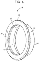
- FIG. 3 depicts a prior art grease lubricated bushing 2.
- This simple bushing 2 has a flange 4 at a first end and a sleeve 6 extending from the flange 4 to a second end.
- Prior art grease lubricated bushings 2 provide the ability to pass electrical current because there is direct contact between the metal housing, metal bushing 2, and metal shaft. These prior art grease lubricated bushings 2 use an electrically conductive grease.
- Prior art bushings do not provide an adequate pathway for electric current while retaining a long service life without the need to re-lubricate the bushing.
- a plain bearing element with inhomogeneous anti-friction layer includes a support layer with bearing material applied to the support layer. Indentations in the supporting layer extend axially apart from one another in the circumferential direction and are filled with plain bearing material. The groove widths of the indentations are between web widths remaining in the depressions.
- a support bearing includes a part in the form of a disc or plate pierced with a central hole for a shaft, provided with a groove. Lubricant fills these grooves. Radially arranged channels connect the successive grooves. The grooves are made in one of the faces or both sides of the plate and are all eccentrically disposed with respect to the axis.
- a method and system for an electrically conductive self-lubricating bearing includes a mating structure having a mating surface and an electrically conductive substrate.
- the substrate includes a substrate surface having a plurality of valleys defined by at least one electrically conductive rib extending therefrom.
- Lubricating material is disposed within the plurality of valleys.
- An exposed surface of the lubricating material is substantially flush with an end defining a length of the rib so as to be communicated with the substrate surface and the mating surface.
- the rib is in electrical communication with the mating surface.
- PTFE polytetrafluoroethylene
- a bushing system for aircraft landing gear.
- the bushing system includes a cylindrical wall that has an interior surface that is defined by a bore which extends between a first axial end and a second axial end thereof.
- the bushing system includes one or more cylindrical recesses that extend radially outward into the interior surface and are located between the first axial end and the second axial end.
- the bushing system includes one or more cylindrical self-lubricating liners each of which are disposed in a respective one of the cylindrical recesses. A radially inward facing surface of the cylindrical self-lubricating liner is substantially flush with the interior surface that defines the bore.
- the bushing system includes an electrically conductive path that is configured to conduct electrical current, preferably an electrical current that has a voltage equivalent to that of a lightning strike.
- the electrically conductive path extends around the cylindrical self-lubricating liners and through the cylindrical wall.
- the bushing system includes the cylindrical wall that has a flange extending radially outward from the cylindrical wall, proximate to the first axial end, the flange having an axial width measured between an outboard axial surface to an inboard axial surface of the flange, one or more annular recesses that extend into the inboard axial surface, one or more annular self-lubricating liners each of which have a planar axial bearing surface and are disposed in a respective one of the annular recesses, the planar axial bearing surface of the annular self-lubricating liner being coplanar with the inboard axial surface and the electrically conductive path extending around the annular self-lubricating liner and through the flange.
- the bushing system also includes the radially inward facing surface of the cylindrical self-lubricating liner that has a liner circumferential surface area, the interior surface having a cylindrical wall circumferential surface area, the electrically conductive path being defined by a first contact area ratio of the liner circumferential surface area divided by the cylindrical wall circumferential surface area, the first contact area ratio being from about 0.40 to about 0.60.
- the bushing system further includes a shaft coated with an electrically conductive wear resistant coating, preferably a tungsten carbide material, on a portion thereof. The wear resistant coating on the shaft is in rotational sliding engagement with the radially inward facing surface of the cylindrical self-lubricating liner and with the interior surface of the cylindrical wall.
- the interior surface that defines the bore includes a first interior surface having a first inside diameter and a second interior surface having a second inside diameter of a magnitude about equal to the first inside diameter.
- the cylindrical recess has a third inside diameter of a magnitude greater than that of the first inside diameter and the second inside diameter.
- a recess radial depth ratio of the first inside diameter or the second inside diameter to the third inside diameter is between 0.90 and 1.00.
- the cylindrical self-lubricating liner has a first axial width and the cylindrical wall extends a second axial width and a ratio of the first axial width to the second axial width is from about 0.50 to about 0.90.
- the annular self-lubricating liner has a first axial thickness, the flange has a second axial thickness, and a ratio of the first axial thickness to the second axial thickness is between about 0.20 and about 0.40.
- the planar axial bearing surface of the annular self-lubricating liner has a liner axial surface area, the inboard axial surface of the flange has a flange axial surface area and a second contact area ratio is defined by liner axial surface area divided by the flange axial surface area, the second contact area ratio being about 0.40 to about 0.80.
- the cylindrical self-lubricating liner and/or the annular self-lubricating liner are made with Polytetrafluoroethylene (PTFE) or has PTFE fibers woven therein.
- PTFE Polytetrafluoroethylene
- the bushing system with the shaft having the wear resistant coating Z may have a maximum wear of 0.0033mm (0.00013 inches) after 25,000 cycles of operation in a temperature range of -53.9°C (-65F) to+162.8°C (+325F).
- the cylindrical self-lubricating liner extends one of: (a) entirely circumferentially within the bore; and (b) intermittently within the bore.
- the cylindrical wall and the flange comprise an aluminum-bronze alloy material.
- the bushing system 10 includes a cylindrical wall 12 that extends from (e.g., between) a first axial end 14 to a second axial end 16 of the bushing system 10.
- the cylindrical wall 12 defines interior surfaces 21, 23 that define a bore 20.
- the interior surface 21 extends axially inward from the first axial end 14 and the interior surface 23 extends axially inward from the second axial end 16.
- a cylindrical recess 24 e.g., an annular groove
- the interior surfaces 21, 23 are shown having approximately equal axial lengths, but the present invention is not limited in this regard as the interior surfaces 21, 23 may have different axial lengths.
- the cylindrical recess 24 extends continuously (i.e., uninterrupted) circumferentially in the cylindrical wall 12.
- a cylindrical self-lubricating liner 22 is disposed (e.g., secured, press fit, adhesively bonded or molded) in the cylindrical recess 24.
- the cylindrical self-lubricating liner 22 extends continuously (i.e., uninterrupted) circumferentially in the cylindrical recess 24.
- a radially inward facing surface 22X of the cylindrical self-lubricating liner 22 is substantially flush with the interior surface 21, 23 that define the bore 20.
- the cylindrical self-lubricating liner 22 is axially centered in the bore 20 to allow the cylindrical self-lubricating liner 22 to carry a significant portion of the load transferred by a pin or shaft 40 (depicted in FIGS. 2 and 6 ) and to provide an adequate lubrication system.
- the cylindrical self-lubricating liner 22 is a single cylindrical surface that is continuous axially and circumferentially within the cylindrical recess 24.
- FIG. 8 depicts an alternate embodiment of a bushing 10' with more than one self-lubricating liner 22', with each self-lubricating liner 22' disposed in a separate recess 24'.
- FIG. 8A illustrates five distinct bands of the self-lubricating liner 22' each of which are disposed in a respective one of the recesses 24'. As shown in FIG.
- the five bands of the self-lubricating liner 22' are equally spaced apart from one another in the respective recess 24' which are also equally spaced apart from one another.
- the liner 22' is a self-lubricating liner manufactured from material similar to the liner 22, as disclosed herein.
- cylindrical recess 24 is shown and described as extending continuously (i.e., uninterrupted) circumferentially in the cylindrical wall 12 and the cylindrical self-lubricating liner 22 is shown and described as extending continuously (i.e., uninterrupted) circumferentially in the cylindrical recess 24, the present invention is not limited in this regard, as other configurations may be employed including but not limited to the cylindrical self-lubricating liner 22 being made up of multiple cylindrical segments 22Z ( FIG. 8B ) disposed in the recess 25, the cylindrical self-lubricating liner 22 having axial slits 22K1 ( FIG.
- the cylindrical self-lubricating liner 22 having circumferential slits 22K2 ( FIG. 8D ) extending through the radially inward facing surface 22X and partially into the cylindrical self-lubricating liner 22, and the cylindrical recess 25 may be interrupted by axially extending bridge portions 21B ( FIG. 8E ).
- the cylindrical wall 12 further includes a flange 26 that extends radially outward from the cylindrical wall 12 proximate the first axial end 14.
- the flange 26 has an axial width T2 measured between an outboard axial surface 27 to an inboard axial surface 28 of the flange 26.
- the inboard axial surface 29 faces toward the second axial end 16 of the cylindrical wall 12 and the outboard axial surface 27 faces away from the second axial end 16 of the cylindrical wall 12.
- the inboard axial surface 29 has an annular recess 25 that extends axially into the flange 26 from the inboard axial surface 29 towards the outboard axial surface 27 and terminating therebetween.
- the annular recess 25 extends continuously (i.e., uninterrupted) in the flange 26.
- An annular self-lubricating liner 28 is disposed in the annular recess 25.
- the annular self-lubricating liner 28 has a planar axial bearing surface 28X which is coplanar with the inboard axial surface 20.
- the annular self-lubricating liner 28 extends continuously circumferentially around and in the annular recess 25.
- annular self-lubricating liner 28 is shown and described as being disposed in the annular recess 25, the present invention is not limited in this regard as the flange 26 may have more than one annular self-lubrication liners disposed in a one respective more than one annular recess.
- the flange 16 has a first annular recess 25' with a self-lubricating liner 28' disposed therein and a second annular recess 25" with a second self-lubricating liner 28" disposed therein.
- annular self-lubricating liner 28 is shown and described as extending continuously circumferentially around and in the annular recess 25 and the annular recess 25 is shown and described as extending continuously (i.e., uninterrupted) in the flange 26, the present invention is not limited in this regard as other configurations may be employed including but not limited to the annular self-lubricating liner 28 being made up of multiple coaxial annular liners 28R ( FIG. 8F ) multiple annular segments 28Z ( FIG. 8G ) disposed in the recess 25, the annular self-lubricating liner 28 having radial slits 28K1 ( FIG.
- annular self-lubricating liner 25 having circumferential slits 25K2 ( FIG. 8I ) extending through the planar axial bearing surface 28X and partially into the annular self-lubricating liner 25, and the annular recess 25 may be interrupted by radially extending bridge portions 29B ( FIG. 8J ) of the 29 inboard axial surface in the flange 26.
- the bushing system 10 has electrically conductive paths 34, 36 configured to conduct electrical current therethrough.
- the electrically conductive paths extend around the cylindrical self-lubricating liner 22 and the annular self-lubricating liner 28.
- the electrically conductive path 34 extends through the cylindrical wall 12 and the electrically conductive path 36 extends through the flange 26.
- the size and location of the cylindrical self-lubricating liner 22 and the annular self-lubricating liner 28 provides adequate lubrication with the shaft 40, while providing the respective electrically conductive path 34, 36 (i.e., through the cylindrical wall 12 and the flange 26) between the shaft 40 and the housing 30 (See FIG. 2 ).
- the first electrically conductive path 34 flows current through the housing 30 to an exterior surface 12E of the cylindrical wall 12, through the cylindrical wall 12 via the interior surfaces 21 and 23 to the shaft 40 and through the shaft 40.
- a second electrically conductive path 36 flows current through the housing 30, through the flange 26 via the inboard axial surface 29 into the cylindrical wall 12, into the shaft 40 via the interior surfaces 21 and 23 and through the shaft 40.
- the electrically conductive paths 34, 36 are configured to conduct electrical current that has a voltage equivalent to that of a lightning strike without causing damage to the cylindrical self-lubricating liner 22, the annular self-lubricating liner 28, the cylindrical wall 12 or the flange 26.
- the electrically conductive paths 34, 36 are also configured to conduct electrical current caused by static electricity, for example, radio signal generated static electricity.
- the cylindrical self-lubricating liner 22 and the annular self-lubricating liner 28 are made from a machinable liner or woven fabric liner each including (e.g., infused with) a polytetrafluoroethylene (PTFE) material.
- PTFE polytetrafluoroethylene
- One such self-lubricating liner is a Uniflon HP liner manufactured by the Heim division of Roller Bearing Company of America, Inc.
- the cylindrical self-lubricating liner 22 and the annular self-lubricating liner 28 provide maintenance-free operation.
- the bushing system 10 is electrically conductive.
- the bushing system 10 is not sealed, is not intended to be greased at maintenance intervals (i.e., maintenance-free), and has sufficient electrical conductivity in to provide an electrically conductive path through the bushing system 10 sufficient for a flow of current equal to that of a lightning strike.
- landing gear assemblies 100 on modern commercial or military aircraft include twenty or more locations where the bushing systems 10 can be employed.
- an external seal is employed over the bushing system 10.
- the bushing system 10 disclosed herein provides an electrically conductive, maintenance-free or low-maintenance bushing for the aircraft landing gear assemblies 100 (e.g., on the Airbus ® A-320 aircraft).
- the bushing system10 is configured for use with Boeing ® and/or Airbus ® A-320 aircraft.
- the Airbus ® A-320 aircraft have an overall length of 37.57 meters, a cabin length of 27.51 meters, a fuselage width of 3.95 meters, a maximum cabin width of 3.70 meters, a wing span of 35.60 meters, a height of 11.76 meters and a wheel base of 12.64 meters.
- the Airbus ® A-320 has a maximum seating capacity of 194 and has a water volume of 44 cubic meters.
- the Airbus ® A-320 has a range of 6,300 kilometers and has weight of 64.30 tonnes with no fuel.
- the Airbus ® A-320 has a maximum fuel capacity of 26,730 liters.
- the Airbus ® A-320 can be fitted with the PurePower PW1100G-JM from Pratt and Whitney or the LEAP-1A from CFM International.
- an articulating joint 99 of the landing gear assembly 100 (See FIG. 1 ) includes a first linkage 90A that is pivotally connected to a second linkage 90B by a shaft 40.
- One of the bushing systems 10 is disposed in each of two housing bores 30B of opposing housing portions 30 of the second linkage 90B.
- the shaft 40 is in fixed relation to the first linkage 90A and is in rotational sliding engagement with an inside surface of the bushing systems 10, as described herein.
- the first linkage 90 and the second linkage 90B are pivotable relative to one another as shown by the arrow R. Axial forces as shown by the arrow F are applied to the articulating joint 99 by the first linkage 90A.
- the interior surface 21 has a first inside diameter D1 and the interior surface 23 has a second inside diameter D2.
- the first inside diameter D1 and the second inside diameter D2 are substantially the equal in magnitude.
- the cylindrical recess 24 has an inside diameter D3.
- the cylindrical self-lubricating liner 22 has an inside diameter D4 that is substantially the equal in magnitude to the first and second inside diameters D1 and D2, respectively.
- the cylindrical self-lubricating liner 22 has an outside diameter that is about equal to the inside diameter D3 of the cylindrical recess 24.
- the radially inward facing surface 22X has an inside diameter D4 that is about equal to the first inside diameter D1 and is about equal to the second inside diameter D2.
- the inside diameter D4 has a magnitude that is less than the inside diameter D1 or the inside diameter D2 so that the cylindrical self-lubricating liner 22 is radially spaced apart from the interior surface 21 and/or the interior surface 23.
- a recess radial depth ratio of the inside diameter D3 of the cylindrical recess to the inside diameter D1 is between 0.90 and 1.00.
- the recess radial depth ratio of the inside diameter D3 of the cylindrical recess to the inside diameter D2 is between 0.90 and 1.00.
- the self-lubricating liner 22 extends an axial length W1 in the bore between the interior surface 21 and the interior surface 23.
- the bushing system 10 has an overall axial length W2.
- the ratio of the axial length W1 of the self-lubricating liner 22 to the overall axial length W2 of the bushing system 10 is approximately 0.55. In some embodiments, the ratio of the axial length W1 of the self-lubricating liner 22 to the overall axial length W2 of the bushing system 10 is between 0.50 and 0.75. In some embodiments, the ratio of the axial length W1 of the self-lubricating liner 22 to the overall axial length W2 of the bushing system 10 is between 0.50 and 0.90.
- the annular self-lubricating liner 28 has a first axial thickness T1 and the flange has a second axial thickness T2.
- a ratio of the first axial thickness T1 to the second axial thickness T2 is between about 0.20 and about 0.40.
- the radially inward facing surface 22X of the cylindrical self-lubricating liner 22 has a liner circumferential surface area A1 and the interior surfaces 21, 23 collectively have a cylindrical wall circumferential surface area A2.
- the planar axial bearing surface 28X of annular self-lubricating liner 28 has a liner axial surface area A3.
- a contact area ratio is defined by the liner circumferential surface area A1 divided by the cylindrical wall circumferential surface area A2. The contact area ratio is about 0.40 to about 0.60.
- contact area ratio of about 0.40 to about 0.60 provides an optimum amount of self-lubrication while providing sufficient metal to metal electrically conductive contact between the cylindrical wall circumferential surface area A2 and the shaft 40 to conduct electrical current of a magnitude equal to a lightning strike.
- the planar axial bearing surface 28X of the annular self-lubricating liner 28 has a liner axial surface area A3 and the inboard axial surface 29 of the flange 16 has flange axial surface area A4.
- Another contact area ratio is defined by liner axial surface area A3 divided by the flange axial surface area A4.
- the second contact area ratio is about 0.40 to about 0.80.
- cylindrical wall 12 and flange 16 of the bushing system 10 is made from an electrically conductive material such as a metallic material, for example, an Aluminum-Bronze alloy.
- a shaft 40 has a wear resistant material (e.g., wear resistant coating 41) thereon.
- the shaft 40 is manufactured from a steel alloy.
- the wear resistant coating 41 is applied via a High Velocity Oxygen Fuel (HVOF) process which is a thermal spray coating process that applies molten materials (or semi-molten materials) at a high speed on substrates, such as the shaft 40.
- HVOF High Velocity Oxygen Fuel
- the wear resistant coating 41 is applied via a physical vapor deposition (PVD) process in which a solid material is vaporized in a vacuum and deposited onto the surface of a part, such as the shaft 40.
- the wear resistant coating 41 is applied via a plating process, for example chromium plating.
- the wear resistant coating 41 is a tungsten carbide material.
- the wear resistant coating 41 is electrically conductive.
- the Applicant has performed wear testing of the bushing system 10 according to SAE standard AS81934, "Bearings, Sleeve, Plain and Flanged, Self-Lubricating, General Specification.
- SAE Standard AS81934 covers plain and flanged sleeve bearings which are self-lubricating by incorporating polytetrafluoroethylene (PTFE) in a liner in the bore for use in a temperature range of -53.9°C (-65F) to +162.8°C (+325F).
- PTFE polytetrafluoroethylene
- SAE Standard AS81934 sets forth a maximum allowable wear of 0.1mm (0.004 inches).
- the Applicant has performed wear testing of the bushing system 10 with a shaft 40 therein and without any contaminants.
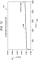
- FIG. 10 is a graph 800 that plots wear in inches on the Y-axis 801 (ordinate) and number of cycles on the X-axis 802 (abscissa).
- the wear test results plotted in the graph 800 are for the bushing 10 with a shaft 40 having a tungsten carbide wear resistant coating thereon.
- the plot 810B is for a baseline test case in which no contaminants were employed.
- the plot 810B exhibited about of 0.0033mm (0.00013 inches) of wear in 25,000 cycles, which is 40 times less than the 0.1mm (0.004 inches) maximum allowable wear pursuant to SAE Standard AS81934.
Landscapes
- Engineering & Computer Science (AREA)
- General Engineering & Computer Science (AREA)
- Mechanical Engineering (AREA)
- Physics & Mathematics (AREA)
- Fluid Mechanics (AREA)
- Aviation & Aerospace Engineering (AREA)
- Sliding-Contact Bearings (AREA)
Description
- The device disclosed herein relates to, but is not limited to, bushings for landing gear on modern commercial and military aircraft. Specifically, the disclosure is directed to bushings with self-lubricated liners that do not require re-greasing or other maintenance that provide a path for conducting an electrical current between a moving structure and another structure.
- Generally, existing landing gear bushings for aerospace applications require periodic maintenance and/or re-greasing. Longer life bushings sacrifice electrical conductivity by containing additional permanent or semi-permanent lubrication. There is a need in the art for a bushing that maintains electrical conductibility without the need for periodic maintenance.
- Aircraft must manage weight, structural strength, and electrical currents. These electrical currents are caused by electromagnetic effects (EME) such as lightning strikes to radio towers and static discharge and electrically conductive paths and/or electrical isolation are required. EME, such as lightning, may have large currents and high voltages capable of producing electrical arcing across exposed surfaces. In aircraft made with non-conductive composite materials, good electrical paths are required to dissipate EME energy, and good electrical isolation is required to protect sensitive equipment and fluids. Bonding and grounding requirements such as in wing ice protection systems must also be provided for aircraft electrical systems.
-
FIG. 3 depicts a prior art grease lubricated bushing 2. Thissimple bushing 2 has a flange 4 at a first end and a sleeve 6 extending from the flange 4 to a second end. Prior art grease lubricatedbushings 2 provide the ability to pass electrical current because there is direct contact between the metal housing,metal bushing 2, and metal shaft. These prior art grease lubricatedbushings 2 use an electrically conductive grease. Prior art bushings do not provide an adequate pathway for electric current while retaining a long service life without the need to re-lubricate the bushing. - As disclosed in the related patent
AT392522B - As disclosed in the related patent
FR518923A - As disclosed in the related patent
US20050175266A1 , a method and system for an electrically conductive self-lubricating bearing includes a mating structure having a mating surface and an electrically conductive substrate. The substrate includes a substrate surface having a plurality of valleys defined by at least one electrically conductive rib extending therefrom. Lubricating material is disposed within the plurality of valleys. An exposed surface of the lubricating material is substantially flush with an end defining a length of the rib so as to be communicated with the substrate surface and the mating surface. The rib is in electrical communication with the mating surface. - One material of liner that is employed in existing landing gear is polytetrafluoroethylene (PTFE), which is not electrically conductive. Therefore, known self-lubricating bushings such as PTFE bushings do not conduct electricity therethrough. As such, conduction of electrical current resulting from a lightning strike or static electricity through aircraft hardware may be impeded, causing damage to the bushing or other components.
- In a first aspect, a bushing system according to claim 1 for aircraft landing gear is provided. The bushing system includes a cylindrical wall that has an interior surface that is defined by a bore which extends between a first axial end and a second axial end thereof. The bushing system includes one or more cylindrical recesses that extend radially outward into the interior surface and are located between the first axial end and the second axial end. The bushing system includes one or more cylindrical self-lubricating liners each of which are disposed in a respective one of the cylindrical recesses. A radially inward facing surface of the cylindrical self-lubricating liner is substantially flush with the interior surface that defines the bore. The bushing system includes an electrically conductive path that is configured to conduct electrical current, preferably an electrical current that has a voltage equivalent to that of a lightning strike. The electrically conductive path extends around the cylindrical self-lubricating liners and through the cylindrical wall. The bushing system includes the cylindrical wall that has a flange extending radially outward from the cylindrical wall, proximate to the first axial end, the flange having an axial width measured between an outboard axial surface to an inboard axial surface of the flange, one or more annular recesses that extend into the inboard axial surface, one or more annular self-lubricating liners each of which have a planar axial bearing surface and are disposed in a respective one of the annular recesses, the planar axial bearing surface of the annular self-lubricating liner being coplanar with the inboard axial surface and the electrically conductive path extending around the annular self-lubricating liner and through the flange. The bushing system also includes the radially inward facing surface of the cylindrical self-lubricating liner that has a liner circumferential surface area, the interior surface having a cylindrical wall circumferential surface area, the electrically conductive path being defined by a first contact area ratio of the liner circumferential surface area divided by the cylindrical wall circumferential surface area, the first contact area ratio being from about 0.40 to about 0.60. The bushing system further includes a shaft coated with an electrically conductive wear resistant coating, preferably a tungsten carbide material, on a portion thereof. The wear resistant coating on the shaft is in rotational sliding engagement with the radially inward facing surface of the cylindrical self-lubricating liner and with the interior surface of the cylindrical wall. The interior surface that defines the bore includes a first interior surface having a first inside diameter and a second interior surface having a second inside diameter of a magnitude about equal to the first inside diameter. The cylindrical recess has a third inside diameter of a magnitude greater than that of the first inside diameter and the second inside diameter. A recess radial depth ratio of the first inside diameter or the second inside diameter to the third inside diameter is between 0.90 and 1.00. The cylindrical self-lubricating liner has a first axial width and the cylindrical wall extends a second axial width and a ratio of the first axial width to the second axial width is from about 0.50 to about 0.90. The annular self-lubricating liner has a first axial thickness, the flange has a second axial thickness, and a ratio of the first axial thickness to the second axial thickness is between about 0.20 and about 0.40. The planar axial bearing surface of the annular self-lubricating liner has a liner axial surface area, the inboard axial surface of the flange has a flange axial surface area and a second contact area ratio is defined by liner axial surface area divided by the flange axial surface area, the second contact area ratio being about 0.40 to about 0.80. The cylindrical self-lubricating liner and/or the annular self-lubricating liner are made with Polytetrafluoroethylene (PTFE) or has PTFE fibers woven therein. The bushing system with the shaft having the wear resistant coating Z may have a maximum wear of 0.0033mm (0.00013 inches) after 25,000 cycles of operation in a temperature range of -53.9°C (-65F) to+162.8°C (+325F).
- In one embodiment, the cylindrical self-lubricating liner extends one of: (a) entirely circumferentially within the bore; and (b) intermittently within the bore.
- In one embodiment, the cylindrical wall and the flange comprise an aluminum-bronze alloy material.
-
-
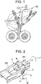
FIG. 1 depicts a landing gear assembly that incorporates one embodiment of an electrically conductive bushing system according to the present disclosure; -
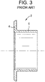
FIG. 2 depicts an isometric partial view of an articulating joint that incorporates one embodiment of the electrically conductive bushing systems according to the present disclosure; -
FIG. 3 a side section view of a prior art bushing; -
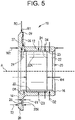
FIG. 4 is an isometric view of an electrically conductive bushing system according to the present disclosure; -
FIG. 5 is a side sectional view of the electrically conductive bushing system ofFIG. 4 ; -
FIG. 6 is a partial side sectional view of the electrically conductive bushing system ofFIG. 4 installed in a housing and with a shaft extending therethrough; -
FIG. 7 is a partial side section view of the electrically conductive bushing system ofFIG. 4 ; -
FIG. 8A is a partial side section view of another embodiment of an electrically conductive bushing system according to the present disclosure; -
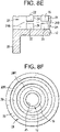
FIG. 8B is a partial side section view of another embodiment of an electrically conductive bushing system according to the present disclosure and having multi-segmented liners; -
FIG. 8C is a cross sectional view of another embodiment of an electrically conductive bushing system according toFIG. 8A and having liners with axial slits; -
FIG. 8D is a partial side section view of another embodiment of an electrically conductive bushing system according to the present disclosure and having circumferential slits; -
FIG. 8E is a partial side section view of another embodiment of an electrically conductive bushing system according to the present disclosure with recesses interrupted by axially extending bridge portions; -
FIG. 8F is an end view of an electrically conductive bushing system according to the present disclosure and having concentrically located recesses and liners; -
FIG. 8G is and end view of an electrically conductive bushing system according to the present disclosure and having a line with multiple annular segments; -
FIG. 8H is a cross sectional view of an annular liner having a radial slit therein; -
FIG. 8I is a perspective view of an annular liner having a circumferential slit therein; -
FIG. 8J is an end view of the electrically conductive bushing system according to the present disclosure and having radial extending bridges interrupting the annular recess; -
FIG. 9 is a partial side sectional view of the electrically conductive bushing ofFIG. 4 installed in a housing with a coated shaft extending therethrough; and -
FIG. 10 is a graph that plots bushing wear as function of cycles. - Referring to
FIGS. 4 ,5 and7 , the bushing system of the present invention is designated byelement number 10. Thebushing system 10 includes acylindrical wall 12 that extends from (e.g., between) a firstaxial end 14 to a secondaxial end 16 of thebushing system 10. Thecylindrical wall 12 definesinterior surfaces bore 20. Theinterior surface 21 extends axially inward from the firstaxial end 14 and theinterior surface 23 extends axially inward from the secondaxial end 16. As best shown inFIG. 5 , a cylindrical recess 24 (e.g., an annular groove) extends radially outward into the interior surfaces 21, 23 and is located between the firstaxial end 14 and the secondaxial end 16. The interior surfaces 21, 23 are shown having approximately equal axial lengths, but the present invention is not limited in this regard as the interior surfaces 21, 23 may have different axial lengths. Thecylindrical recess 24 extends continuously (i.e., uninterrupted) circumferentially in thecylindrical wall 12. A cylindrical self-lubricatingliner 22 is disposed (e.g., secured, press fit, adhesively bonded or molded) in thecylindrical recess 24. The cylindrical self-lubricatingliner 22 extends continuously (i.e., uninterrupted) circumferentially in thecylindrical recess 24. A radially inward facingsurface 22X of the cylindrical self-lubricatingliner 22 is substantially flush with theinterior surface bore 20. - In the embodiment depicted in
FIGS. 4 ,5 and7 , the cylindrical self-lubricatingliner 22 is axially centered in thebore 20 to allow the cylindrical self-lubricatingliner 22 to carry a significant portion of the load transferred by a pin or shaft 40 (depicted inFIGS. 2 and6 ) and to provide an adequate lubrication system. The cylindrical self-lubricatingliner 22 is a single cylindrical surface that is continuous axially and circumferentially within thecylindrical recess 24. - While one of the
cylindrical recesses 24 with one cylindrical self-lubricatingliner 22 is shown and described with reference toFIG. 5 , the present invention is not limited in this regard as more than one recess and self-lubricating liner having different cross sections may be employed without departing from the broader aspects of the present invention. For example,FIG. 8 depicts an alternate embodiment of a bushing 10' with more than one self-lubricating liner 22', with each self-lubricating liner 22' disposed in a separate recess 24'. In particular,FIG. 8A illustrates five distinct bands of the self-lubricating liner 22' each of which are disposed in a respective one of the recesses 24'. As shown inFIG. 8 , the five bands of the self-lubricating liner 22' are equally spaced apart from one another in the respective recess 24' which are also equally spaced apart from one another. The liner 22' is a self-lubricating liner manufactured from material similar to theliner 22, as disclosed herein. - While the
cylindrical recess 24 is shown and described as extending continuously (i.e., uninterrupted) circumferentially in thecylindrical wall 12 and the cylindrical self-lubricatingliner 22 is shown and described as extending continuously (i.e., uninterrupted) circumferentially in thecylindrical recess 24, the present invention is not limited in this regard, as other configurations may be employed including but not limited to the cylindrical self-lubricatingliner 22 being made up of multiplecylindrical segments 22Z (FIG. 8B ) disposed in therecess 25, the cylindrical self-lubricatingliner 22 having axial slits 22K1 (FIG. 8C ) extending through the radially inward facingsurface 22X and partially into the cylindrical self-lubricatingliner 22, the cylindrical self-lubricatingliner 22 having circumferential slits 22K2 (FIG. 8D ) extending through the radially inward facingsurface 22X and partially into the cylindrical self-lubricatingliner 22, and thecylindrical recess 25 may be interrupted by axially extendingbridge portions 21B (FIG. 8E ). - Referring back to
FIG. 5 , thecylindrical wall 12 further includes aflange 26 that extends radially outward from thecylindrical wall 12 proximate the firstaxial end 14. Theflange 26 has an axial width T2 measured between an outboardaxial surface 27 to an inboardaxial surface 28 of theflange 26. The inboardaxial surface 29 faces toward the secondaxial end 16 of thecylindrical wall 12 and the outboardaxial surface 27 faces away from the secondaxial end 16 of thecylindrical wall 12. The inboardaxial surface 29 has anannular recess 25 that extends axially into theflange 26 from the inboardaxial surface 29 towards the outboardaxial surface 27 and terminating therebetween. Theannular recess 25 extends continuously (i.e., uninterrupted) in theflange 26. An annular self-lubricatingliner 28 is disposed in theannular recess 25. The annular self-lubricatingliner 28 has a planaraxial bearing surface 28X which is coplanar with the inboardaxial surface 20. The annular self-lubricatingliner 28 extends continuously circumferentially around and in theannular recess 25. - While one annular self-lubricating
liner 28 is shown and described as being disposed in theannular recess 25, the present invention is not limited in this regard as theflange 26 may have more than one annular self-lubrication liners disposed in a one respective more than one annular recess. For example, as shown inFIG. 8F theflange 16 has a first annular recess 25' with a self-lubricating liner 28' disposed therein and a secondannular recess 25" with a second self-lubricatingliner 28" disposed therein. While the annular self-lubricatingliner 28 is shown and described as extending continuously circumferentially around and in theannular recess 25 and theannular recess 25 is shown and described as extending continuously (i.e., uninterrupted) in theflange 26, the present invention is not limited in this regard as other configurations may be employed including but not limited to the annular self-lubricatingliner 28 being made up of multiple coaxialannular liners 28R (FIG. 8F ) multipleannular segments 28Z (FIG. 8G ) disposed in therecess 25, the annular self-lubricatingliner 28 having radial slits 28K1 (FIG. 8H ) extending through the planaraxial bearing surface 28X and partially into the annular self-lubricatingliner 28, the annular self-lubricatingliner 25 having circumferential slits 25K2 (FIG. 8I ) extending through the planaraxial bearing surface 28X and partially into the annular self-lubricatingliner 25, and theannular recess 25 may be interrupted by radially extendingbridge portions 29B (FIG. 8J ) of the 29 inboard axial surface in theflange 26. - As shown in
FIG. 6 , thebushing system 10 has electricallyconductive paths liner 22 and the annular self-lubricatingliner 28. The electricallyconductive path 34 extends through thecylindrical wall 12 and the electricallyconductive path 36 extends through theflange 26. - As shown in
FIG. 6 , the size and location of the cylindrical self-lubricatingliner 22 and the annular self-lubricatingliner 28 provides adequate lubrication with theshaft 40, while providing the respective electricallyconductive path 34, 36 (i.e., through thecylindrical wall 12 and the flange 26) between theshaft 40 and the housing 30 (SeeFIG. 2 ). In particular, the first electricallyconductive path 34 flows current through thehousing 30 to an exterior surface 12E of thecylindrical wall 12, through thecylindrical wall 12 via the interior surfaces 21 and 23 to theshaft 40 and through theshaft 40. A second electricallyconductive path 36 flows current through thehousing 30, through theflange 26 via the inboardaxial surface 29 into thecylindrical wall 12, into theshaft 40 via the interior surfaces 21 and 23 and through theshaft 40. The electricallyconductive paths liner 22, the annular self-lubricatingliner 28, thecylindrical wall 12 or theflange 26. The electricallyconductive paths - The cylindrical self-lubricating
liner 22 and the annular self-lubricatingliner 28 are made from a machinable liner or woven fabric liner each including (e.g., infused with) a polytetrafluoroethylene (PTFE) material. One such self-lubricating liner is a Uniflon HP liner manufactured by the Heim division of Roller Bearing Company of America, Inc. The cylindrical self-lubricatingliner 22 and the annular self-lubricatingliner 28 provide maintenance-free operation. Thebushing system 10 is electrically conductive. Thebushing system 10 is not sealed, is not intended to be greased at maintenance intervals (i.e., maintenance-free), and has sufficient electrical conductivity in to provide an electrically conductive path through thebushing system 10 sufficient for a flow of current equal to that of a lightning strike. - Referring to
FIG. 1 ,landing gear assemblies 100 on modern commercial or military aircraft (e.g., Airbus ® A-320 aircraft) include twenty or more locations where thebushing systems 10 can be employed. In some embodiments, an external seal is employed over thebushing system 10. Thebushing system 10 disclosed herein provides an electrically conductive, maintenance-free or low-maintenance bushing for the aircraft landing gear assemblies 100 (e.g., on the Airbus ® A-320 aircraft). The bushing system10 is configured for use with Boeing® and/or Airbus ® A-320 aircraft. - The Airbus ® A-320 aircraft have an overall length of 37.57 meters, a cabin length of 27.51 meters, a fuselage width of 3.95 meters, a maximum cabin width of 3.70 meters, a wing span of 35.60 meters, a height of 11.76 meters and a wheel base of 12.64 meters. The Airbus ® A-320 has a maximum seating capacity of 194 and has a water volume of 44 cubic meters. The Airbus ® A-320 has a range of 6,300 kilometers and has weight of 64.30 tonnes with no fuel. The Airbus ® A-320 has a maximum fuel capacity of 26,730 liters. The Airbus ® A-320 can be fitted with the PurePower PW1100G-JM from Pratt and Whitney or the LEAP-1A from CFM International.
- As shown in
FIG. 2 , an articulatingjoint 99 of the landing gear assembly 100 (SeeFIG. 1 ) includes afirst linkage 90A that is pivotally connected to asecond linkage 90B by ashaft 40. One of thebushing systems 10 is disposed in each of twohousing bores 30B of opposinghousing portions 30 of thesecond linkage 90B. Theshaft 40 is in fixed relation to thefirst linkage 90A and is in rotational sliding engagement with an inside surface of thebushing systems 10, as described herein. The first linkage 90 and thesecond linkage 90B are pivotable relative to one another as shown by the arrow R. Axial forces as shown by the arrow F are applied to the articulating joint 99 by thefirst linkage 90A. - Referring to
FIG. 5 , theinterior surface 21 has a first inside diameter D1 and theinterior surface 23 has a second inside diameter D2. The first inside diameter D1 and the second inside diameter D2 are substantially the equal in magnitude. Thecylindrical recess 24 has an inside diameter D3. The cylindrical self-lubricatingliner 22 has an inside diameter D4 that is substantially the equal in magnitude to the first and second inside diameters D1 and D2, respectively. The cylindrical self-lubricatingliner 22 has an outside diameter that is about equal to the inside diameter D3 of thecylindrical recess 24. The radially inward facingsurface 22X has an inside diameter D4 that is about equal to the first inside diameter D1 and is about equal to the second inside diameter D2. In some embodiments, the inside diameter D4 has a magnitude that is less than the inside diameter D1 or the inside diameter D2 so that the cylindrical self-lubricatingliner 22 is radially spaced apart from theinterior surface 21 and/or theinterior surface 23. In some embodiments, a recess radial depth ratio of the inside diameter D3 of the cylindrical recess to the inside diameter D1 is between 0.90 and 1.00. In some embodiments, the recess radial depth ratio of the inside diameter D3 of the cylindrical recess to the inside diameter D2 is between 0.90 and 1.00. - Referring to
FIG. 5 , the self-lubricatingliner 22 extends an axial length W1 in the bore between theinterior surface 21 and theinterior surface 23. Thebushing system 10 has an overall axial length W2. The ratio of the axial length W1 of the self-lubricatingliner 22 to the overall axial length W2 of thebushing system 10 is approximately 0.55. In some embodiments, the ratio of the axial length W1 of the self-lubricatingliner 22 to the overall axial length W2 of thebushing system 10 is between 0.50 and 0.75. In some embodiments, the ratio of the axial length W1 of the self-lubricatingliner 22 to the overall axial length W2 of thebushing system 10 is between 0.50 and 0.90. - As shown in
FIG. 5 , the annular self-lubricatingliner 28 has a first axial thickness T1 and the flange has a second axial thickness T2. A ratio of the first axial thickness T1 to the second axial thickness T2 is between about 0.20 and about 0.40. - The radially inward facing
surface 22X of the cylindrical self-lubricatingliner 22 has a liner circumferential surface area A1 and the interior surfaces 21, 23 collectively have a cylindrical wall circumferential surface area A2. The planaraxial bearing surface 28X of annular self-lubricatingliner 28 has a liner axial surface area A3. A contact area ratio is defined by the liner circumferential surface area A1 divided by the cylindrical wall circumferential surface area A2. The contact area ratio is about 0.40 to about 0.60. The applicant has surprisingly found that contact area ratio of about 0.40 to about 0.60 provides an optimum amount of self-lubrication while providing sufficient metal to metal electrically conductive contact between the cylindrical wall circumferential surface area A2 and theshaft 40 to conduct electrical current of a magnitude equal to a lightning strike. - The planar
axial bearing surface 28X of the annular self-lubricatingliner 28 has a liner axial surface area A3 and the inboardaxial surface 29 of theflange 16 has flange axial surface area A4. Another contact area ratio is defined by liner axial surface area A3 divided by the flange axial surface area A4. The second contact area ratio is about 0.40 to about 0.80. - In one embodiment the
cylindrical wall 12 andflange 16 of thebushing system 10 is made from an electrically conductive material such as a metallic material, for example, an Aluminum-Bronze alloy. - As shown in
FIG. 9 , ashaft 40 has a wear resistant material (e.g., wear resistant coating 41) thereon. In some embodiments, theshaft 40 is manufactured from a steel alloy. In one embodiment, the wearresistant coating 41 is applied via a High Velocity Oxygen Fuel (HVOF) process which is a thermal spray coating process that applies molten materials (or semi-molten materials) at a high speed on substrates, such as theshaft 40. In one embodiment, the wearresistant coating 41 is applied via a physical vapor deposition (PVD) process in which a solid material is vaporized in a vacuum and deposited onto the surface of a part, such as theshaft 40. In one embodiment, the wearresistant coating 41 is applied via a plating process, for example chromium plating. In one embodiment the wearresistant coating 41 is a tungsten carbide material. The wearresistant coating 41 is electrically conductive. - The Applicant has performed wear testing of the
bushing system 10 according to SAE standard AS81934, "Bearings, Sleeve, Plain and Flanged, Self-Lubricating, General Specification. SAE Standard AS81934 covers plain and flanged sleeve bearings which are self-lubricating by incorporating polytetrafluoroethylene (PTFE) in a liner in the bore for use in a temperature range of -53.9°C (-65F) to +162.8°C (+325F). SAE Standard AS81934 sets forth a maximum allowable wear of 0.1mm (0.004 inches). The Applicant has performed wear testing of thebushing system 10 with ashaft 40 therein and without any contaminants. - The tests were performed with the
bushing systems 10 anduncoated shafts 40 and thebushing systems 10 andshafts 40 with a wearresistant coating 41 thereon. For example,FIG. 10 is agraph 800 that plots wear in inches on the Y-axis 801 (ordinate) and number of cycles on the X-axis 802 (abscissa). The wear test results plotted in thegraph 800 are for thebushing 10 with ashaft 40 having a tungsten carbide wear resistant coating thereon. Theplot 810B is for a baseline test case in which no contaminants were employed. Theplot 810B exhibited about of 0.0033mm (0.00013 inches) of wear in 25,000 cycles, which is 40 times less than the 0.1mm (0.004 inches) maximum allowable wear pursuant to SAE Standard AS81934. - Although this invention has been shown and described with respect to the detailed embodiments thereof, it will be understood by those of skill in the art that various changes may be made within the scope of the appended claims.
Claims (3)
- A bushing system (10) for aircraft landing gear (100), the bushing system (10) comprising:a cylindrical wall (12) having an interior surface (21, 23) defining a bore (20) extending between a first axial end (14) and a second axial end (16) thereof, and at least one cylindrical recess (24, 24') extending radially outward into the interior surface (21, 23) and located between the first axial end (14) and the second axial end (16);at least one cylindrical self-lubricating liner (22, 22') disposed in the at least one cylindrical recess (24, 24'), a radially inward facing surface (22X) of the at least one cylindrical self-lubricating liner (22, 22') being substantially flush with the interior surface (21, 23) defining the bore (20);an electrically conductive path (34) configured to conduct electrical current, preferably an electrical current that has a voltage equivalent to that of a lightning strike, the electrically conductive path (34) extending around the at least one cylindrical self-lubricating liner (22, 22'), the electrically conductive path (34) extending through the cylindrical wall (12);the cylindrical wall (12) further comprising a flange (26) extending radially outward from the cylindrical wall (12) proximate to the first axial end (16), the flange (26) having an axial width (T2) measured between an outboard axial surface (27) to an inboard axial surface (29) of the flange (26), at least one annular recess (25, 25') extending into the inboard axial surface (29), at least one annular self-lubricating liner (28) defining a planar axial bearing surface (28X), the at least one annular self-lubricating liner (28) being disposed in the at least one annular recess (25, 25'), the planar axial bearing surface (28X) of the at least one annular self-lubricating liner (28) being coplanar with the inboard axial surface (29) and the electrically conductive path (34) extending around the at least one annular self-lubricating liner (28), the electrically conductive path (34) extending through the flange (26);the radially inward facing surface (22X) of the at least one cylindrical self-lubricating liner (22) having a liner circumferential surface area (A1), the interior surface (21, 23) having a cylindrical wall circumferential surface area (A2), the electrically conductive path (34) being defined by a first contact area ratio of the liner circumferential surface area (A1) divided by the cylindrical wall circumferential surface area (A2), the first contact area ratio being from about 0.40 to about 0.60; characterized in thata shaft (40) coated with an electrically conductive wear resistant coating (41), preferably a tungsten carbide material, on at least a portion thereof, the wear resistant coating (41) on the shaft (40) being in rotational sliding engagement with the radially inward facing surface (22X) of the at least one cylindrical self-lubricating liner (22) and with the interior surface (21, 23) of the cylindrical wall (12),wherein the interior surface (21, 23) defining the bore (20) further comprises:a first interior surface (21) having a first inside diameter D1);a second interior surface (23) having a second inside diameter (D2) of a magnitude about equal to the first inside diameter (D1); andthe at least one cylindrical recess (24, 24') having a third inside diameter (D3) of a magnitude greater than that of the first inside diameter (D1) and that of the second inside diameter (D2);wherein a recess radial depth ratio of the first inside diameter (D1) or the second inside diameter (D2) to the third inside diameter (D3) is between 0.90 and 1.00,wherein the at least one cylindrical self-lubricating liner (22) has a first axial width (W1) and the cylindrical wall (12) extends a second axial width (W2) and a ratio of the first axial width (W1) to the second axial width (W2) is from about 0.50 to about 0.90,wherein the at least one annular self-lubricating liner (28) has a first axial thickness (T1), the flange (26) has a second axial thickness (T2), and a ratio of the first axial thickness (T1) to the second axial thickness (T2) is between about 0.20 and about 0.40,wherein the planar axial bearing surface (28X) of the at least one annular self-lubricating liner (28) has a liner axial surface area (A3), the inboard axial surface (29) of the flange (26) has a flange axial surface area (A4) and a second contact area ratio is defined by liner axial surface area (A3) divided by the flange axial surface area (A4), the second contact area ratio being about 0.40 to about 0.80,wherein at least one of the cylindrical self-lubricating liner (22) and the at least one annular self-lubricating liner (28) comprises Polytetrafluoroethylene (PTFE) or has PTFE fibers woven therein.
- The bushing system (10) of claim 1, wherein the at least one cylindrical self-lubricating liner (22) extends one of: (a) entirely circumferentially within the bore (20) and (b) intermittently within the bore (20).
- The bushing system (10) of claim 1 or 2, wherein the cylindrical wall (12) and the flange comprise an aluminum-bronze alloy material.
Priority Applications (1)
| Application Number | Priority Date | Filing Date | Title |
|---|---|---|---|
| EP22174382.6A EP4063264B1 (en) | 2019-06-07 | 2020-06-05 | Self-lubricated electrically conductive bushing |
Applications Claiming Priority (2)
| Application Number | Priority Date | Filing Date | Title |
|---|---|---|---|
| US201962858438P | 2019-06-07 | 2019-06-07 | |
| US202063028095P | 2020-05-21 | 2020-05-21 |
Related Child Applications (2)
| Application Number | Title | Priority Date | Filing Date |
|---|---|---|---|
| EP22174382.6A Division EP4063264B1 (en) | 2019-06-07 | 2020-06-05 | Self-lubricated electrically conductive bushing |
| EP22174382.6A Division-Into EP4063264B1 (en) | 2019-06-07 | 2020-06-05 | Self-lubricated electrically conductive bushing |
Publications (2)
| Publication Number | Publication Date |
|---|---|
| EP3747765A1 EP3747765A1 (en) | 2020-12-09 |
| EP3747765B1 true EP3747765B1 (en) | 2022-08-03 |
Family
ID=71016404
Family Applications (2)
| Application Number | Title | Priority Date | Filing Date |
|---|---|---|---|
| EP22174382.6A Active EP4063264B1 (en) | 2019-06-07 | 2020-06-05 | Self-lubricated electrically conductive bushing |
| EP20178483.2A Active EP3747765B1 (en) | 2019-06-07 | 2020-06-05 | Self-lubricated electrically conductive bushing |
Family Applications Before (1)
| Application Number | Title | Priority Date | Filing Date |
|---|---|---|---|
| EP22174382.6A Active EP4063264B1 (en) | 2019-06-07 | 2020-06-05 | Self-lubricated electrically conductive bushing |
Country Status (3)
| Country | Link |
|---|---|
| US (1) | US11560923B2 (en) |
| EP (2) | EP4063264B1 (en) |
| CN (1) | CN112081826A (en) |
Families Citing this family (3)
| Publication number | Priority date | Publication date | Assignee | Title |
|---|---|---|---|---|
| EP3751161B1 (en) * | 2019-06-14 | 2023-09-27 | Safran Landing Systems UK Ltd | Self-lubricating bush assembly |
| US11460070B2 (en) * | 2020-01-03 | 2022-10-04 | The Boeing Company | Self-repair bearing and methods |
| GB2605424A (en) * | 2021-03-31 | 2022-10-05 | Airbus Operations Ltd | Axle Sleeve |
Family Cites Families (20)
| Publication number | Priority date | Publication date | Assignee | Title |
|---|---|---|---|---|
| FR518923A (en) | 1914-03-17 | 1921-06-02 | Bound Brook Oil Less Bearing | Thrust bearing |
| US2906925A (en) | 1955-05-10 | 1959-09-29 | Joslyn Mfg & Supply Co | Aircraft lightning arrester |
| AT392522B (en) | 1986-03-22 | 1991-04-25 | Glyco Metall Werke | SLIDE BEARING ELEMENT WITH INHOMOGENIC ANTIFRICTION LAYER |
| US5000586A (en) * | 1988-02-23 | 1991-03-19 | Metal Leve S.A. Industria E. Commercio | Sliding bearing |
| JP3185433B2 (en) | 1992-12-29 | 2001-07-09 | オイレス工業株式会社 | Cylindrical bearings with solid lubricant embedded and fixed on the inner peripheral surface |
| KR20010040354A (en) | 1998-01-19 | 2001-05-15 | 메드퀘스트 프러덕츠 인코퍼레이티드 | Method and apparatus for providing a conductive, amorphous non-stick coating |
| JP4416455B2 (en) | 2002-10-22 | 2010-02-17 | Nokクリューバー株式会社 | Conductive grease bearing |
| US20050175266A1 (en) | 2004-02-11 | 2005-08-11 | Kamatics Corporation | Electrically conductive self-lubricating bearing system and a method for implementing same |
| EP1975424A1 (en) | 2007-03-29 | 2008-10-01 | Saint-Gobain Performance Plastics Pampus Gmbh | Sliding bearing material which can be calibrated |
| US20140339358A1 (en) | 2007-12-06 | 2014-11-20 | Roller Bearing Company Of America, Inc. | Electrical conductor for lined track rollers used on actuation system for aircraft lift assisting devices |
| US8393791B2 (en) | 2009-08-17 | 2013-03-12 | The Boeing Company | Bearing side face electrical isolation |
| EP2467916A4 (en) | 2009-08-21 | 2014-06-04 | Titeflex Corp | ENERGY DISSIPATING TUBES, SEALING DEVICES AND METHODS OF MANUFACTURING AND INSTALLATION THEREOF |
| FR2952146B1 (en) | 2009-10-29 | 2011-11-25 | Messier Dowty Sa | CONTROL GAME LINK DEVICE |
| JP5432971B2 (en) * | 2011-02-15 | 2014-03-05 | 株式会社神戸製鋼所 | Sliding member and manufacturing method thereof |
| CN104245748B (en) | 2012-04-26 | 2016-09-07 | 美蓓亚株式会社 | Ultra-violet solidified resin composition and slide unit and the manufacture method of slide unit |
| EP3006751B1 (en) | 2014-09-17 | 2018-11-07 | Roller Bearing Company of America, Inc. | System for isolating electrical current in a bearing for use in an aircraft structure |
| US9856910B2 (en) * | 2015-11-30 | 2018-01-02 | Roller Bearing Company Of America, Inc. | Self-lubricated thrust bearing for a hinged aircraft wing |
| CN105537382A (en) | 2016-02-18 | 2016-05-04 | 沈阳北阳氟塑料有限公司 | Machining bushing for aviation |
| US10480569B2 (en) * | 2017-06-15 | 2019-11-19 | Schaublin Sa | Hybrid lined trunnion bearing for aircraft landing gear |
| EP3751160B1 (en) * | 2019-06-14 | 2021-09-15 | Safran Landing Systems UK Limited | Self-lubricating conductive bearing |
-
2020
- 2020-06-04 US US16/892,348 patent/US11560923B2/en active Active
- 2020-06-05 EP EP22174382.6A patent/EP4063264B1/en active Active
- 2020-06-05 EP EP20178483.2A patent/EP3747765B1/en active Active
- 2020-06-08 CN CN202010512789.4A patent/CN112081826A/en active Pending
Also Published As
| Publication number | Publication date |
|---|---|
| EP4063264A1 (en) | 2022-09-28 |
| EP4063264B1 (en) | 2025-12-17 |
| EP4063264C0 (en) | 2025-12-17 |
| US20210269146A1 (en) | 2021-09-02 |
| EP3747765A1 (en) | 2020-12-09 |
| CN112081826A (en) | 2020-12-15 |
| US11560923B2 (en) | 2023-01-24 |
Similar Documents
| Publication | Publication Date | Title |
|---|---|---|
| EP4063264B1 (en) | Self-lubricated electrically conductive bushing | |
| EP0054380B1 (en) | Slip ring and brush assemblies | |
| US7480996B2 (en) | Truck pivot joint bearing and method of lubricating | |
| US8393791B2 (en) | Bearing side face electrical isolation | |
| EP3751160B1 (en) | Self-lubricating conductive bearing | |
| US20030095729A1 (en) | Hybrid bearing system | |
| US10724575B2 (en) | Metallic lined trunnion bearing for aircraft landing gear | |
| US20190226526A1 (en) | Electrical insulating device for bearings | |
| CA2057002A1 (en) | Solid-lubricated bearing assembly | |
| EP2986863B1 (en) | Dynamic plain bearing | |
| EP3418593B1 (en) | Hybrid lined trunnion bearing for aircraft landing gear | |
| US20150336658A1 (en) | Bearing installed on an aircraft structure | |
| US20200370597A1 (en) | Electrically conductive and self-lubricating bearing liner, bearing containing the same, and method of manufacturing such a bearing liner | |
| US12612941B2 (en) | Field serviceable landing gear bushing | |
| US20010022934A1 (en) | Lubricating system for thermal medium delivery parts in a gas turbine | |
| US20050175266A1 (en) | Electrically conductive self-lubricating bearing system and a method for implementing same | |
| EP3587846B1 (en) | Metallic lined trunnion bearing for aircraft landing gear | |
| CN219827474U (en) | Sliding bearing and roller with the sliding bearing | |
| US12012994B2 (en) | Bearing assembly | |
| EP3118474B1 (en) | Lubrication for an expendable bearing | |
| EP1074698A2 (en) | A lubricating coating for tubes in gas turbines | |
| CA2934173A1 (en) | Lubrication for an expendable bearing |
Legal Events
| Date | Code | Title | Description |
|---|---|---|---|
| PUAI | Public reference made under article 153(3) epc to a published international application that has entered the european phase |
Free format text: ORIGINAL CODE: 0009012 |
|
| STAA | Information on the status of an ep patent application or granted ep patent |
Free format text: STATUS: THE APPLICATION HAS BEEN PUBLISHED |
|
| AK | Designated contracting states |
Kind code of ref document: A1 Designated state(s): AL AT BE BG CH CY CZ DE DK EE ES FI FR GB GR HR HU IE IS IT LI LT LU LV MC MK MT NL NO PL PT RO RS SE SI SK SM TR |
|
| AX | Request for extension of the european patent |
Extension state: BA ME |
|
| STAA | Information on the status of an ep patent application or granted ep patent |
Free format text: STATUS: REQUEST FOR EXAMINATION WAS MADE |
|
| 17P | Request for examination filed |
Effective date: 20210604 |
|
| RBV | Designated contracting states (corrected) |
Designated state(s): AL AT BE BG CH CY CZ DE DK EE ES FI FR GB GR HR HU IE IS IT LI LT LU LV MC MK MT NL NO PL PT RO RS SE SI SK SM TR |
|
| GRAP | Despatch of communication of intention to grant a patent |
Free format text: ORIGINAL CODE: EPIDOSNIGR1 |
|
| STAA | Information on the status of an ep patent application or granted ep patent |
Free format text: STATUS: GRANT OF PATENT IS INTENDED |
|
| INTG | Intention to grant announced |
Effective date: 20220121 |
|
| GRAS | Grant fee paid |
Free format text: ORIGINAL CODE: EPIDOSNIGR3 |
|
| GRAA | (expected) grant |
Free format text: ORIGINAL CODE: 0009210 |
|
| STAA | Information on the status of an ep patent application or granted ep patent |
Free format text: STATUS: THE PATENT HAS BEEN GRANTED |
|
| AK | Designated contracting states |
Kind code of ref document: B1 Designated state(s): AL AT BE BG CH CY CZ DE DK EE ES FI FR GB GR HR HU IE IS IT LI LT LU LV MC MK MT NL NO PL PT RO RS SE SI SK SM TR |
|
| REG | Reference to a national code |
Ref country code: AT Ref legal event code: REF Ref document number: 1508550 Country of ref document: AT Kind code of ref document: T Effective date: 20220815 Ref country code: CH Ref legal event code: EP |
|
| REG | Reference to a national code |
Ref country code: DE Ref legal event code: R096 Ref document number: 602020004299 Country of ref document: DE |
|
| REG | Reference to a national code |
Ref country code: IE Ref legal event code: FG4D |
|
| REG | Reference to a national code |
Ref country code: LT Ref legal event code: MG9D |
|
| REG | Reference to a national code |
Ref country code: NL Ref legal event code: MP Effective date: 20220803 |
|
| PG25 | Lapsed in a contracting state [announced via postgrant information from national office to epo] |
Ref country code: SE Free format text: LAPSE BECAUSE OF FAILURE TO SUBMIT A TRANSLATION OF THE DESCRIPTION OR TO PAY THE FEE WITHIN THE PRESCRIBED TIME-LIMIT Effective date: 20220803 Ref country code: RS Free format text: LAPSE BECAUSE OF FAILURE TO SUBMIT A TRANSLATION OF THE DESCRIPTION OR TO PAY THE FEE WITHIN THE PRESCRIBED TIME-LIMIT Effective date: 20220803 Ref country code: PT Free format text: LAPSE BECAUSE OF FAILURE TO SUBMIT A TRANSLATION OF THE DESCRIPTION OR TO PAY THE FEE WITHIN THE PRESCRIBED TIME-LIMIT Effective date: 20221205 Ref country code: NO Free format text: LAPSE BECAUSE OF FAILURE TO SUBMIT A TRANSLATION OF THE DESCRIPTION OR TO PAY THE FEE WITHIN THE PRESCRIBED TIME-LIMIT Effective date: 20221103 Ref country code: NL Free format text: LAPSE BECAUSE OF FAILURE TO SUBMIT A TRANSLATION OF THE DESCRIPTION OR TO PAY THE FEE WITHIN THE PRESCRIBED TIME-LIMIT Effective date: 20220803 Ref country code: LV Free format text: LAPSE BECAUSE OF FAILURE TO SUBMIT A TRANSLATION OF THE DESCRIPTION OR TO PAY THE FEE WITHIN THE PRESCRIBED TIME-LIMIT Effective date: 20220803 Ref country code: LT Free format text: LAPSE BECAUSE OF FAILURE TO SUBMIT A TRANSLATION OF THE DESCRIPTION OR TO PAY THE FEE WITHIN THE PRESCRIBED TIME-LIMIT Effective date: 20220803 Ref country code: FI Free format text: LAPSE BECAUSE OF FAILURE TO SUBMIT A TRANSLATION OF THE DESCRIPTION OR TO PAY THE FEE WITHIN THE PRESCRIBED TIME-LIMIT Effective date: 20220803 Ref country code: ES Free format text: LAPSE BECAUSE OF FAILURE TO SUBMIT A TRANSLATION OF THE DESCRIPTION OR TO PAY THE FEE WITHIN THE PRESCRIBED TIME-LIMIT Effective date: 20220803 |
|
| REG | Reference to a national code |
Ref country code: AT Ref legal event code: MK05 Ref document number: 1508550 Country of ref document: AT Kind code of ref document: T Effective date: 20220803 |
|
| PG25 | Lapsed in a contracting state [announced via postgrant information from national office to epo] |
Ref country code: PL Free format text: LAPSE BECAUSE OF FAILURE TO SUBMIT A TRANSLATION OF THE DESCRIPTION OR TO PAY THE FEE WITHIN THE PRESCRIBED TIME-LIMIT Effective date: 20220803 Ref country code: IS Free format text: LAPSE BECAUSE OF FAILURE TO SUBMIT A TRANSLATION OF THE DESCRIPTION OR TO PAY THE FEE WITHIN THE PRESCRIBED TIME-LIMIT Effective date: 20221203 Ref country code: HR Free format text: LAPSE BECAUSE OF FAILURE TO SUBMIT A TRANSLATION OF THE DESCRIPTION OR TO PAY THE FEE WITHIN THE PRESCRIBED TIME-LIMIT Effective date: 20220803 Ref country code: GR Free format text: LAPSE BECAUSE OF FAILURE TO SUBMIT A TRANSLATION OF THE DESCRIPTION OR TO PAY THE FEE WITHIN THE PRESCRIBED TIME-LIMIT Effective date: 20221104 |
|
| PG25 | Lapsed in a contracting state [announced via postgrant information from national office to epo] |
Ref country code: SM Free format text: LAPSE BECAUSE OF FAILURE TO SUBMIT A TRANSLATION OF THE DESCRIPTION OR TO PAY THE FEE WITHIN THE PRESCRIBED TIME-LIMIT Effective date: 20220803 Ref country code: RO Free format text: LAPSE BECAUSE OF FAILURE TO SUBMIT A TRANSLATION OF THE DESCRIPTION OR TO PAY THE FEE WITHIN THE PRESCRIBED TIME-LIMIT Effective date: 20220803 Ref country code: DK Free format text: LAPSE BECAUSE OF FAILURE TO SUBMIT A TRANSLATION OF THE DESCRIPTION OR TO PAY THE FEE WITHIN THE PRESCRIBED TIME-LIMIT Effective date: 20220803 Ref country code: CZ Free format text: LAPSE BECAUSE OF FAILURE TO SUBMIT A TRANSLATION OF THE DESCRIPTION OR TO PAY THE FEE WITHIN THE PRESCRIBED TIME-LIMIT Effective date: 20220803 Ref country code: AT Free format text: LAPSE BECAUSE OF FAILURE TO SUBMIT A TRANSLATION OF THE DESCRIPTION OR TO PAY THE FEE WITHIN THE PRESCRIBED TIME-LIMIT Effective date: 20220803 |
|
| REG | Reference to a national code |
Ref country code: DE Ref legal event code: R097 Ref document number: 602020004299 Country of ref document: DE |
|
| PG25 | Lapsed in a contracting state [announced via postgrant information from national office to epo] |
Ref country code: SK Free format text: LAPSE BECAUSE OF FAILURE TO SUBMIT A TRANSLATION OF THE DESCRIPTION OR TO PAY THE FEE WITHIN THE PRESCRIBED TIME-LIMIT Effective date: 20220803 Ref country code: EE Free format text: LAPSE BECAUSE OF FAILURE TO SUBMIT A TRANSLATION OF THE DESCRIPTION OR TO PAY THE FEE WITHIN THE PRESCRIBED TIME-LIMIT Effective date: 20220803 |
|
| PLBE | No opposition filed within time limit |
Free format text: ORIGINAL CODE: 0009261 |
|
| STAA | Information on the status of an ep patent application or granted ep patent |
Free format text: STATUS: NO OPPOSITION FILED WITHIN TIME LIMIT |
|
| PG25 | Lapsed in a contracting state [announced via postgrant information from national office to epo] |
Ref country code: AL Free format text: LAPSE BECAUSE OF FAILURE TO SUBMIT A TRANSLATION OF THE DESCRIPTION OR TO PAY THE FEE WITHIN THE PRESCRIBED TIME-LIMIT Effective date: 20220803 |
|
| 26N | No opposition filed |
Effective date: 20230504 |
|
| PG25 | Lapsed in a contracting state [announced via postgrant information from national office to epo] |
Ref country code: SI Free format text: LAPSE BECAUSE OF FAILURE TO SUBMIT A TRANSLATION OF THE DESCRIPTION OR TO PAY THE FEE WITHIN THE PRESCRIBED TIME-LIMIT Effective date: 20220803 |
|
| PG25 | Lapsed in a contracting state [announced via postgrant information from national office to epo] |
Ref country code: MC Free format text: LAPSE BECAUSE OF FAILURE TO SUBMIT A TRANSLATION OF THE DESCRIPTION OR TO PAY THE FEE WITHIN THE PRESCRIBED TIME-LIMIT Effective date: 20220803 |
|
| PG25 | Lapsed in a contracting state [announced via postgrant information from national office to epo] |
Ref country code: MC Free format text: LAPSE BECAUSE OF FAILURE TO SUBMIT A TRANSLATION OF THE DESCRIPTION OR TO PAY THE FEE WITHIN THE PRESCRIBED TIME-LIMIT Effective date: 20220803 |
|
| REG | Reference to a national code |
Ref country code: BE Ref legal event code: MM Effective date: 20230630 |
|
| PG25 | Lapsed in a contracting state [announced via postgrant information from national office to epo] |
Ref country code: LU Free format text: LAPSE BECAUSE OF NON-PAYMENT OF DUE FEES Effective date: 20230605 |
|
| REG | Reference to a national code |
Ref country code: IE Ref legal event code: MM4A |
|
| PG25 | Lapsed in a contracting state [announced via postgrant information from national office to epo] |
Ref country code: LU Free format text: LAPSE BECAUSE OF NON-PAYMENT OF DUE FEES Effective date: 20230605 |
|
| PG25 | Lapsed in a contracting state [announced via postgrant information from national office to epo] |
Ref country code: IE Free format text: LAPSE BECAUSE OF NON-PAYMENT OF DUE FEES Effective date: 20230605 |
|
| PG25 | Lapsed in a contracting state [announced via postgrant information from national office to epo] |
Ref country code: IE Free format text: LAPSE BECAUSE OF NON-PAYMENT OF DUE FEES Effective date: 20230605 |
|
| PG25 | Lapsed in a contracting state [announced via postgrant information from national office to epo] |
Ref country code: IT Free format text: LAPSE BECAUSE OF FAILURE TO SUBMIT A TRANSLATION OF THE DESCRIPTION OR TO PAY THE FEE WITHIN THE PRESCRIBED TIME-LIMIT Effective date: 20220803 Ref country code: FR Free format text: LAPSE BECAUSE OF NON-PAYMENT OF DUE FEES Effective date: 20230630 Ref country code: BE Free format text: LAPSE BECAUSE OF NON-PAYMENT OF DUE FEES Effective date: 20230630 |
|
| PG25 | Lapsed in a contracting state [announced via postgrant information from national office to epo] |
Ref country code: BG Free format text: LAPSE BECAUSE OF FAILURE TO SUBMIT A TRANSLATION OF THE DESCRIPTION OR TO PAY THE FEE WITHIN THE PRESCRIBED TIME-LIMIT Effective date: 20220803 |
|
| PG25 | Lapsed in a contracting state [announced via postgrant information from national office to epo] |
Ref country code: BG Free format text: LAPSE BECAUSE OF FAILURE TO SUBMIT A TRANSLATION OF THE DESCRIPTION OR TO PAY THE FEE WITHIN THE PRESCRIBED TIME-LIMIT Effective date: 20220803 |
|
| GBPC | Gb: european patent ceased through non-payment of renewal fee |
Effective date: 20240605 |
|
| PG25 | Lapsed in a contracting state [announced via postgrant information from national office to epo] |
Ref country code: GB Free format text: LAPSE BECAUSE OF NON-PAYMENT OF DUE FEES Effective date: 20240605 |
|
| PGFP | Annual fee paid to national office [announced via postgrant information from national office to epo] |
Ref country code: DE Payment date: 20250627 Year of fee payment: 6 |
|
| PG25 | Lapsed in a contracting state [announced via postgrant information from national office to epo] |
Ref country code: CY Free format text: LAPSE BECAUSE OF FAILURE TO SUBMIT A TRANSLATION OF THE DESCRIPTION OR TO PAY THE FEE WITHIN THE PRESCRIBED TIME-LIMIT; INVALID AB INITIO Effective date: 20200605 |
|
| PG25 | Lapsed in a contracting state [announced via postgrant information from national office to epo] |
Ref country code: HU Free format text: LAPSE BECAUSE OF FAILURE TO SUBMIT A TRANSLATION OF THE DESCRIPTION OR TO PAY THE FEE WITHIN THE PRESCRIBED TIME-LIMIT; INVALID AB INITIO Effective date: 20200605 |
|
| PGFP | Annual fee paid to national office [announced via postgrant information from national office to epo] |
Ref country code: CH Payment date: 20250701 Year of fee payment: 6 |
|
| PG25 | Lapsed in a contracting state [announced via postgrant information from national office to epo] |
Ref country code: TR Free format text: LAPSE BECAUSE OF FAILURE TO SUBMIT A TRANSLATION OF THE DESCRIPTION OR TO PAY THE FEE WITHIN THE PRESCRIBED TIME-LIMIT Effective date: 20220803 |