EP3747739A1 - Universal high expandable filling member - Google Patents
Universal high expandable filling member Download PDFInfo
- Publication number
- EP3747739A1 EP3747739A1 EP19179122.7A EP19179122A EP3747739A1 EP 3747739 A1 EP3747739 A1 EP 3747739A1 EP 19179122 A EP19179122 A EP 19179122A EP 3747739 A1 EP3747739 A1 EP 3747739A1
- Authority
- EP
- European Patent Office
- Prior art keywords
- filling
- mass
- cavity
- expandable material
- longitudinal extension
- Prior art date
- Legal status (The legal status is an assumption and is not a legal conclusion. Google has not performed a legal analysis and makes no representation as to the accuracy of the status listed.)
- Granted
Links
Images

Classifications
-
- B—PERFORMING OPERATIONS; TRANSPORTING
- B62—LAND VEHICLES FOR TRAVELLING OTHERWISE THAN ON RAILS
- B62D—MOTOR VEHICLES; TRAILERS
- B62D25/00—Superstructure or monocoque structure sub-units; Parts or details thereof not otherwise provided for
-
- B—PERFORMING OPERATIONS; TRANSPORTING
- B60—VEHICLES IN GENERAL
- B60R—VEHICLES, VEHICLE FITTINGS, OR VEHICLE PARTS, NOT OTHERWISE PROVIDED FOR
- B60R13/00—Elements for body-finishing, identifying, or decorating; Arrangements or adaptations for advertising purposes
- B60R13/08—Insulating elements, e.g. for sound insulation
-
- B—PERFORMING OPERATIONS; TRANSPORTING
- B62—LAND VEHICLES FOR TRAVELLING OTHERWISE THAN ON RAILS
- B62D—MOTOR VEHICLES; TRAILERS
- B62D29/00—Superstructures, understructures, or sub-units thereof, characterised by the material thereof
- B62D29/001—Superstructures, understructures, or sub-units thereof, characterised by the material thereof characterised by combining metal and synthetic material
- B62D29/002—Superstructures, understructures, or sub-units thereof, characterised by the material thereof characterised by combining metal and synthetic material a foamable synthetic material or metal being added in situ
-
- B—PERFORMING OPERATIONS; TRANSPORTING
- B60—VEHICLES IN GENERAL
- B60R—VEHICLES, VEHICLE FITTINGS, OR VEHICLE PARTS, NOT OTHERWISE PROVIDED FOR
- B60R19/00—Wheel guards; Radiator guards, e.g. grilles; Obstruction removers; Fittings damping bouncing force in collisions
- B60R19/02—Bumpers, i.e. impact receiving or absorbing members for protecting vehicles or fending off blows from other vehicles or objects
- B60R19/18—Bumpers, i.e. impact receiving or absorbing members for protecting vehicles or fending off blows from other vehicles or objects characterised by the cross-section; Means within the bumper to absorb impact
- B60R19/22—Bumpers, i.e. impact receiving or absorbing members for protecting vehicles or fending off blows from other vehicles or objects characterised by the cross-section; Means within the bumper to absorb impact containing mainly cellular material, e.g. solid foam
-
- B—PERFORMING OPERATIONS; TRANSPORTING
- B62—LAND VEHICLES FOR TRAVELLING OTHERWISE THAN ON RAILS
- B62D—MOTOR VEHICLES; TRAILERS
- B62D25/00—Superstructure or monocoque structure sub-units; Parts or details thereof not otherwise provided for
- B62D25/24—Superstructure sub-units with access or drainage openings having movable or removable closures; Sealing means therefor
Definitions
- the present invention relates generally to a cavity filling system for e.g. noise reduction, sealing and/or stiffening.
- the cavity is part of an automotive vehicle structure.
- the present invention further relates to an automotive vehicle structure with a multitude of cavities and a filling system.
- a cavity filling system comprising a structure of an automotive vehicle cavity and a filling member the filling member including:
- the present invention is predicated upon the provision of a filling member suitable for providing sealing, noise reduction and/or structural improvement to a structure comprising a cavity.
- the filling member fills a cavity, particularly its cross section, at least partially, so that a seal is provided, noise is reduced and/or the stiffness of the structure and/or the energy absorption during a crash is improved.
- the filling member may be employed in conjunction with a variety of structures of various vehicles such as boats, trains, trucks, buses, automobiles and/or aeroplanes. It has been found, however, that the member is particularly suitable for application to structures or assemblies of transportation vehicles such as automotive vehicles. Generally, it is contemplated that the member may be applied to various structures such as components of a body, a frame, an engine, a hood, a trunk, a bumper, a pillar, a door or combinations thereof or the like of an automotive vehicle.
- the filling system comprises a carrier member which carries the expandable material.
- This carrier member can, for example, be made of a plastic-, a metal-material or a combination thereof or the like.
- the carrier is a strip shaped piece of material, which preferably comprises a much larger length and width in comparison to its thickness. Even more preferred, the length of the material is larger than the width, preferably significantly larger.
- the carrier is ruler-shaped.
- the carrier is preferably provided at one of the surfaces of the cavity and more preferably extends, at least essentially, parallel to this surface. Due to the plastic and/or elastic deformability, the carrier is preferably adapted to the shape of the cavity, preferably one sidewall of the cavity. The deformation can take place prior and/or during the expansion of the expandable material.
- the filling member comprises a mass of expandable material.
- the expandable material can, if desired, be configured to substantially entirely fill a section of a cavity in which the member has been placed.
- the expandable material typically expands to form a foam that spans across a cross-section of the cavity for inhibiting or prohibiting the passage of mass (e.g., dust and debris) and or sound (e.g., noise) through the cavity.
- the mass of expandable material may be shaped in a variety of different configurations and there may be multiple different masses of expandable material, which are spaced apart from each other, preferably equidistantly.
- the expandable material i.e. the material prior to expansion, is also strip shaped; i.e. it preferably comprises a much larger length and width in comparison to its thickness.
- the expandable material is provided on one surface of the carrier, preferably the surface that is defined by the length and the width of the carrier. Preferably, this surface extends away from the surface of the cavity to which the carrier is attached.
- the mass of expandable material may be formed into a variety of shapes and configurations.
- the walls of the mass may be planar or contoured and the mass may be geometric or non-geometric or a combination thereof.
- the mass of expandable material may be generally shaped as a polyhedron having sidewalls that are respectively square and/or rectangular.
- the volume of the mass of expandable material may be relatively large or relatively small prior to expansion thereof. As such, the size or volume of the mass should not be limited unless otherwise specifically stated. Generally, however, preferred embodiments of the invention have a mass of expandable material with a volume that is greater than about 0.5 cm 3 , more typically greater than about 1.0 cm 3 , and even more typically greater than about 1.5 cm 3 and a volume that is less than about 10 cm 3 , more typically less than about 4.0 cm 3 and even more typically less than about 2.0 cm 3 .
- expandable materials may be used for the mass of expandable material of the present invention.
- the material may be formed of a heat activated material and may flow, cure (e.g., be thermosettable), foam or a combination thereof upon exposure to heat.
- the expandable material may be generally dry to the touch and substantially tack free or may be tacky and, in either situation, may be shaped in any form or desired pattern, placement, or thickness, but is preferably of substantially uniform thickness.
- Exemplary expandable materials are L-7102, L-2806, L-2810, L-2811, L-2820, L-2821 and L-7220 foam available through L&L Products, Inc. of Romeo, Michigan. Another exemplary expandable material is disclosed in U.S. patent application No. 10/867,835 incorporated herein by reference for all purposes.
- a preferred heat activated material is an expandable polymer or plastic, and preferably one that is foamable.
- Particularly preferred materials are epoxy-based, acrylate-based or acetate-based foams, which may be structural, sealing, sound damping, sound absorbing, sound attenuating or a combination thereof.
- the foam may be an epoxy-based material, including an ethylene copolymer or terpolymer that may possess an alpha-olefin.
- the polymer is composed of two or three different monomers, i.e., small molecules with high chemical reactivity that are capable of linking up with similar molecules.
- a number of epoxy-based or otherwise based sealing, baffling or acoustic foams are known in the art and may employed in the present invention.
- a typical foam includes a polymeric base material, such as an epoxy resin or ethylene-based polymer which, when compounded with appropriate ingredients (typically a blowing and curing agent), expands and cures in a reliable and predictable manner upon the application of heat or the occurrence of a particular ambient condition.
- the structural foam is usually initially processed as a flowable thermoplastic material before curing. It will cross-link upon curing, which typically makes the material incapable of further flow (e.g., thermoset).
- the preferred foam materials can be processed in several ways.
- the preferred materials can be processed by injection molding, extrusion, compression molding or with a mini-applicator. This enables the formation and creation of part designs that exceed the capability of most prior art materials.
- the material may also be formed of non-activatable materials, non-expandable materials or otherwise.
- the material may soften, cure and expand; soften and cure only; cure only; soften only; or may be non-activatable.
- an expandable material is the epoxy based resin disclosed in U.S. Patent No. 6,131,897 , the teachings of which are incorporated herein by reference.
- Some other possible materials include, but are not limited to, polyolefin materials, copolymers and terpolymers with at least one monomer type an alpha-olefin, phenol/formaldehyde materials, phenoxy materials, and polyurethane materials with high glass transition temperatures. See also , U.S. Patent Nos. 5,766,719 ; 5,755,486 ; 5,575,526 ; and 5,932,680 , (incorporated by reference).
- desired characteristics of the material can include adhesion durability properties or the like, although such properties are not necessarily required. Generally, it is desirable that the material does not generally interfere with the materials systems employed by automobile manufacturers or other manufactures.
- exemplary expandable materials can include combinations of two or more of the following: epoxy resin, polystyrene, styrene butadiene-styrene (SBS) block copolymer, butadiene acrylo-nitrile rubber, amorphous silica, glass microspheres, azodicarbonamide, urea, dicyandiamide.
- SBS styrene butadiene-styrene
- SIKAELASTOMER SIKAREINFORCER
- SIKABAFFLE commercially available from the Sika Corporation, Madison Heights, MI.
- an important consideration involved with the selection and formulation of the material forming the foam is the temperature at which a material reaction or expansion, and possibly curing, will take place.
- certain expandable material ingredients become reactive at higher processing temperatures, such as those encountered in an automobile assembly plant, when the material is processed and/or activated along with the automobile components at elevated temperatures or at higher applied energy levels, e.g., during paint or e-coat baking or curing steps.
- temperatures encountered in an automobile assembly operation may be in the range of about 148.89° C to 204.44°C (about 300°F to 400°F)
- body and paint shop applications are commonly about 93.33°C (about 200°F) or slightly higher.
- suitable expandable materials have a volumetric range of expansion ranging from approximately 0 to over 1000 percent.
- a mass of expandable material may expand to form a foam that occupies a volume that is (e.g., is at least partially located within) at least 150%, 200%, 500%, 1000%, 1500%, 2000% or 3000% of the volume occupied by the original unexpanded mass of expandable material.
- the material or medium may be at least partially coated with an active polymer having damping characteristics or other heat activated polymer, (e.g., a formable hot melt adhesive based polymer or an expandable structural foam, examples of which include olefinic polymers, vinyl polymers, thermoplastic rubber-containing polymers, epoxies, urethanes or the like) placed along the mold through the use of baffle technology; a die-cast application according to teachings that are well known in the art; pumpable application systems which could include the use of a baffle and bladder system; and sprayable applications.
- an active polymer having damping characteristics or other heat activated polymer e.g., a formable hot melt adhesive based polymer or an expandable structural foam, examples of which include olefinic polymers, vinyl polymers, thermoplastic rubber-containing polymers, epoxies, urethanes or the like
- the filling member comprises an attachment attached to the carrier member, the expandable material or both and locating the filling member relative to one sidewall of the automotive vehicle cavity.
- the attachment may be formed, molded or shaped of the same material and more preferably as one part of the carrier member and/or the expandable material or, alternatively, may be a separate member that is attached or connected to one or both of the expandable material and the carrier member.
- the attachment may also be an attachment medium such as an adhesive or magnetic medium.
- the attachment is elastically deformable., so that it can be compresses during installation of the filling member in the cavity and then expands again at least partially, when the filling member has reached its final position in the cavity of the structure.
- the carrier member has a longitudinal extension and the attachment is preferably provided in the middle of the longitudinal extension.
- the attachment is preferably a fastener that extends into an opening of the structure for at least partially attaching the filling member to the structure of the vehicle.
- the carrier member may comprise pre-tensioning means, which is elastically deformed during installation.
- the pre-tensioning means can be one piece with the carrier and can be, for example one or more wings, which extend from the carrier.
- the mass of expandable material is provided in segments which are spaced apart, more preferably equidistantly,
- the segments preferably have the same shape, but may differ in size, particularly in their longitudinal extension.
- the problem is also solved with a system, wherein the filling members are provided as a kit of multiple identical filling members (1) which only differ in their longitudinal extension.
- the filling elements are provided as a kit which are essentially identical except for their longitudinal extension and the amount of expandable mass provided on the respective carrier.
- This kit allows cover all cavity filling purposes in a vehicle. Thee is no need for complicated tailor made filling elements for a certain specific application.
- the skilled person selects among the members of the kit the most suitable one and apply it to the respective cavity.
- the kit comprises 2 - 4 members, all differing in their longitudinal extension and the amount of expandable mass. These 2 - 4, preferably 3 members are sufficient to fill all cavities in the structure of a vehicle, preferably an automotive vehicle.
- the ratio of mass in kg and length of the filling member in meter off the filling member is 5 - 10, preferably 6 - 9,5, preferably 6,25 - 8,33.
- the filling element is inserted into the cavity to be filled and prior and/or during insertion, the flexible carrier member is plastically and7or elastically deformed.
- the insertion can be manually or automatically, for example by a robot.
- the problem is also solved by a method to produce the inventive kit, wherein one single mold-machine is utilized for all members of the kit and wherein the mold machine is provided with chambers and wherein chambers are opened or closed depending on the desired longitudinal extension of the carrier member and/or the desired amount of expandable mass.
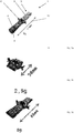
- Figures 1a - c each depict one embodiment of a filling member 1.
- the three embodiments 1a - c are three members of a kit. Every filling element comprises a carrier member, which is strip- or ruler-shaped carrier member 1, which has in the present case a longitudinal extension 10 of 110 mm.
- the carrier member 1 can be made from a plastic material, for example by extrusion or moulding.
- the carrier element can also be made from a metal material, preferably steel.
- the carrier element has a first surface 3 and an opposed second surface 4. On the first surface 3, and only here, the expandable mass 5 is provided, here in five segments, which are provided separate from each other and equidistantly along the first surface 3.
- the segments are here provided strip-shaped. The segments preferably have all the same width and length.
- the filling element 1 is flexible and can be deformed elastically and/or plastically, so that its shape can adapt to the shape of the cavity, particularly to the sidewall of the cavity to which the filling element is attached.
- the three embodiments according to Figures 1a - c are all designed identically but differ in their length and by the amount of expandable material.
- the three embodiments are an example for a kit, which is sufficient for all filling purposes of the structure for a vehicle. Due to this identical and simple design, the cost for providing the filling elements and their stock can be reduced significantly.
- Figure 2 shows a cross section of the filling member 1 and the attachment 6.
- the carrier element comprises at both sides pre-tensioning means 8, here in the form of elastic wings.
- the attachment means 6 comprises here hooks 11, which are inserted into a hole 14 in the structure of the vehicle. During insertion, the hooks are first elastically compressed and, as soon as they have passed the hole expand again. The pre-tensioning means force the hook against the structure of the vehicle.
- Figure 3 shows the filling element 1 in a cavity 7 of the structure of a vehicle. It can be seen that the filling element is attached to the surface of one sidewall 12 of the cavity via the attachment means 6.
- a filling element is selected that is slightly smaller than the longitudinal extension of the cavity.
- the expansion limits of the expandable material is indicated by reference sign 13 and s preferably 4 - 30 mm. For cavities higher than that a different filling element has to be chosen.
- Figure 4 depict the normalized hole, which is identical for all cavities in the vehicle structure.
- the cross section of the hole is preferably square or rectangular.
Landscapes
- Engineering & Computer Science (AREA)
- Mechanical Engineering (AREA)
- Chemical & Material Sciences (AREA)
- Combustion & Propulsion (AREA)
- Transportation (AREA)
- Architecture (AREA)
- Structural Engineering (AREA)
- Physics & Mathematics (AREA)
- Acoustics & Sound (AREA)
- Body Structure For Vehicles (AREA)
- Motor Or Generator Frames (AREA)
Abstract
Description
- The present invention relates generally to a cavity filling system for e.g. noise reduction, sealing and/or stiffening. The cavity is part of an automotive vehicle structure. The present invention further relates to an automotive vehicle structure with a multitude of cavities and a filling system.
- To fill cavities with an expandable material which is provided on a carrier is well known in the state in the art. There are numerous examples of such filling systems, which are tailor made for a specific application. However, there is a constant need for simpler designs, which can be used universally in many if not all cavities of an automotive structure.
- It was therefore the problem of the present invention to provide a cavity filling system that is simple designed and which can be used universally in many if not all cavities of an automotive structure.
- The problem is attained with a cavity filling system comprising a structure of
an automotive vehicle cavity and a filling member
the filling member including: - i. a carrier member comprising a first and a second surface,
- ii. a mass of expandable material located on the surface of the carrier member
- iii. an attachment attached to the carrier member, the expandable material or both and locating the filling member relative to one sidewall of the automotive vehicle cavity;
- The present invention is predicated upon the provision of a filling member suitable for providing sealing, noise reduction and/or structural improvement to a structure comprising a cavity. The filling member fills a cavity, particularly its cross section, at least partially, so that a seal is provided, noise is reduced and/or the stiffness of the structure and/or the energy absorption during a crash is improved.
- It is contemplated that the filling member may be employed in conjunction with a variety of structures of various vehicles such as boats, trains, trucks, buses, automobiles and/or aeroplanes. It has been found, however, that the member is particularly suitable for application to structures or assemblies of transportation vehicles such as automotive vehicles. Generally, it is contemplated that the member may be applied to various structures such as components of a body, a frame, an engine, a hood, a trunk, a bumper, a pillar, a door or combinations thereof or the like of an automotive vehicle.
- According to the present invention, the filling system comprises a carrier member which carries the expandable material. This carrier member can, for example, be made of a plastic-, a metal-material or a combination thereof or the like. Preferably, the carrier is a strip shaped piece of material, which preferably comprises a much larger length and width in comparison to its thickness. Even more preferred, the length of the material is larger than the width, preferably significantly larger. Preferably, the carrier is ruler-shaped. The carrier is preferably provided at one of the surfaces of the cavity and more preferably extends, at least essentially, parallel to this surface. Due to the plastic and/or elastic deformability, the carrier is preferably adapted to the shape of the cavity, preferably one sidewall of the cavity. The deformation can take place prior and/or during the expansion of the expandable material.
- Furthermore, the filling member comprises a mass of expandable material. Upon expansion, the expandable material can, if desired, be configured to substantially entirely fill a section of a cavity in which the member has been placed. In such an embodiment, the expandable material typically expands to form a foam that spans across a cross-section of the cavity for inhibiting or prohibiting the passage of mass (e.g., dust and debris) and or sound (e.g., noise) through the cavity.
- The mass of expandable material may be shaped in a variety of different configurations and there may be multiple different masses of expandable material, which are spaced apart from each other, preferably equidistantly. Preferably, the expandable material, i.e. the material prior to expansion, is also strip shaped; i.e. it preferably comprises a much larger length and width in comparison to its thickness. Preferably, the expandable material is provided on one surface of the carrier, preferably the surface that is defined by the length and the width of the carrier. Preferably, this surface extends away from the surface of the cavity to which the carrier is attached.
- It is contemplated that the mass of expandable material may be formed into a variety of shapes and configurations. The walls of the mass may be planar or contoured and the mass may be geometric or non-geometric or a combination thereof. The mass of expandable material may be generally shaped as a polyhedron having sidewalls that are respectively square and/or rectangular.
- The volume of the mass of expandable material may be relatively large or relatively small prior to expansion thereof. As such, the size or volume of the mass should not be limited unless otherwise specifically stated. Generally, however, preferred embodiments of the invention have a mass of expandable material with a volume that is greater than about 0.5 cm3, more typically greater than about 1.0 cm3, and even more typically greater than about 1.5 cm3 and a volume that is less than about 10 cm3, more typically less than about 4.0 cm3 and even more typically less than about 2.0 cm3.
- A variety of expandable materials may be used for the mass of expandable material of the present invention. In one embodiment, the material may be formed of a heat activated material and may flow, cure (e.g., be thermosettable), foam or a combination thereof upon exposure to heat. The expandable material may be generally dry to the touch and substantially tack free or may be tacky and, in either situation, may be shaped in any form or desired pattern, placement, or thickness, but is preferably of substantially uniform thickness. Exemplary expandable materials are L-7102, L-2806, L-2810, L-2811, L-2820, L-2821 and L-7220 foam available through L&L Products, Inc. of Romeo, Michigan. Another exemplary expandable material is disclosed in
U.S. patent application No. 10/867,835 incorporated herein by reference for all purposes. - Though other heat-activated materials are possible, a preferred heat activated material is an expandable polymer or plastic, and preferably one that is foamable. Particularly preferred materials are epoxy-based, acrylate-based or acetate-based foams, which may be structural, sealing, sound damping, sound absorbing, sound attenuating or a combination thereof. For example, and without limitation, the foam may be an epoxy-based material, including an ethylene copolymer or terpolymer that may possess an alpha-olefin. As a copolymer or terpolymer, the polymer is composed of two or three different monomers, i.e., small molecules with high chemical reactivity that are capable of linking up with similar molecules.
- A number of epoxy-based or otherwise based sealing, baffling or acoustic foams are known in the art and may employed in the present invention. A typical foam includes a polymeric base material, such as an epoxy resin or ethylene-based polymer which, when compounded with appropriate ingredients (typically a blowing and curing agent), expands and cures in a reliable and predictable manner upon the application of heat or the occurrence of a particular ambient condition. From a chemical standpoint for a thermally-activated material, the structural foam is usually initially processed as a flowable thermoplastic material before curing. It will cross-link upon curing, which typically makes the material incapable of further flow (e.g., thermoset).
- One advantage of the preferred foam materials over prior art materials is that the preferred materials can be processed in several ways. The preferred materials can be processed by injection molding, extrusion, compression molding or with a mini-applicator. This enables the formation and creation of part designs that exceed the capability of most prior art materials.
- While preferred materials have been disclosed, other materials may be used as well, particularly materials that are heat-activated or otherwise activated by an ambient condition (e.g. moisture, pressure, time, chemical reaction or the like) and cure in a predictable and reliable manner under appropriate conditions for the selected application. Of course, the material may also be formed of non-activatable materials, non-expandable materials or otherwise. Thus, upon activation, the material may soften, cure and expand; soften and cure only; cure only; soften only; or may be non-activatable.
- One example of an expandable material is the epoxy based resin disclosed in
U.S. Patent No. 6,131,897 , the teachings of which are incorporated herein by reference. Some other possible materials include, but are not limited to, polyolefin materials, copolymers and terpolymers with at least one monomer type an alpha-olefin, phenol/formaldehyde materials, phenoxy materials, and polyurethane materials with high glass transition temperatures. See also,U.S. Patent Nos. 5,766,719 ;5,755,486 ;5,575,526 ; and5,932,680 , (incorporated by reference). In general, desired characteristics of the material can include adhesion durability properties or the like, although such properties are not necessarily required. Generally, it is desirable that the material does not generally interfere with the materials systems employed by automobile manufacturers or other manufactures. - Other exemplary expandable materials can include combinations of two or more of the following: epoxy resin, polystyrene, styrene butadiene-styrene (SBS) block copolymer, butadiene acrylo-nitrile rubber, amorphous silica, glass microspheres, azodicarbonamide, urea, dicyandiamide. Examples of such materials are sold under the tradename SIKAELASTOMER, SIKAREINFORCER and SIKABAFFLE and are commercially available from the Sika Corporation, Madison Heights, MI.
- In applications where the material is a heat activated, thermally expanding and/or foaming material, an important consideration involved with the selection and formulation of the material forming the foam is the temperature at which a material reaction or expansion, and possibly curing, will take place. Typically, certain expandable material ingredients become reactive at higher processing temperatures, such as those encountered in an automobile assembly plant, when the material is processed and/or activated along with the automobile components at elevated temperatures or at higher applied energy levels, e.g., during paint or e-coat baking or curing steps. While temperatures encountered in an automobile assembly operation may be in the range of about 148.89° C to 204.44°C (about 300°F to 400°F), body and paint shop applications are commonly about 93.33°C (about 200°F) or slightly higher. If needed, various different blowing agents or blowing agent activators can be incorporated into the composition to cause expansion at different temperatures outside the above ranges. Generally, suitable expandable materials have a volumetric range of expansion ranging from approximately 0 to over 1000 percent. For example a mass of expandable material may expand to form a foam that occupies a volume that is (e.g., is at least partially located within) at least 150%, 200%, 500%, 1000%, 1500%, 2000% or 3000% of the volume occupied by the original unexpanded mass of expandable material.
- The material or medium may be at least partially coated with an active polymer having damping characteristics or other heat activated polymer, (e.g., a formable hot melt adhesive based polymer or an expandable structural foam, examples of which include olefinic polymers, vinyl polymers, thermoplastic rubber-containing polymers, epoxies, urethanes or the like) placed along the mold through the use of baffle technology; a die-cast application according to teachings that are well known in the art; pumpable application systems which could include the use of a baffle and bladder system; and sprayable applications.
- Additionally, the filling member comprises an attachment attached to the carrier member, the expandable material or both and locating the filling member relative to one sidewall of the automotive vehicle cavity. As such, the attachment may be formed, molded or shaped of the same material and more preferably as one part of the carrier member and/or the expandable material or, alternatively, may be a separate member that is attached or connected to one or both of the expandable material and the carrier member. The attachment may also be an attachment medium such as an adhesive or magnetic medium. Preferably, the attachment is elastically deformable., so that it can be compresses during installation of the filling member in the cavity and then expands again at least partially, when the filling member has reached its final position in the cavity of the structure.
- The carrier member has a longitudinal extension and the attachment is preferably provided in the middle of the longitudinal extension. the attachment is preferably a fastener that extends into an opening of the structure for at least partially attaching the filling member to the structure of the vehicle.
- The carrier member may comprise pre-tensioning means, which is elastically deformed during installation. The pre-tensioning means can be one piece with the carrier and can be, for example one or more wings, which extend from the carrier.
- Preferably, the mass of expandable material is provided in segments which are spaced apart, more preferably equidistantly, The segments preferably have the same shape, but may differ in size, particularly in their longitudinal extension.
- The problem is also solved with a system, wherein the filling members are provided as a kit of multiple identical filling members (1) which only differ in their longitudinal extension.
- The disclosure regarding each filling element is also applicable for this subject matter of the present invention.
- According to this embodiment, the filling elements are provided as a kit which are essentially identical except for their longitudinal extension and the amount of expandable mass provided on the respective carrier. This kit allows cover all cavity filling purposes in a vehicle. Thee is no need for complicated tailor made filling elements for a certain specific application. The skilled person selects among the members of the kit the most suitable one and apply it to the respective cavity. Preferably, the kit comprises 2 - 4 members, all differing in their longitudinal extension and the amount of expandable mass. These 2 - 4, preferably 3 members are sufficient to fill all cavities in the structure of a vehicle, preferably an automotive vehicle.
- Preferably, the ratio of mass in kg and length of the filling member in meter off the filling member is 5 - 10, preferably 6 - 9,5, preferably 6,25 - 8,33.
- The filling element is inserted into the cavity to be filled and prior and/or during insertion, the flexible carrier member is plastically and7or elastically deformed. The insertion can be manually or automatically, for example by a robot.
- The problem is also solved by a method to produce the inventive kit, wherein one single mold-machine is utilized for all members of the kit and wherein the mold machine is provided with chambers and wherein chambers are opened or closed depending on the desired longitudinal extension of the carrier member and/or the desired amount of expandable mass.
- The invention is now further explained according to the Figures. These explanations apply to all embodiments of the present invention. The explanations do not limit the scope of the present invention.
- Figures 1a-1c
- each depict a filling member, wherein the three depicted filling elements are a kit.
- Figure 2
- shows a cross section of the filling member and the attachment means
- Figure 3
- shows the filling element in a cavity
- Figure 4
- shows the normalized hole for all cavities of a vehicle
-
Figures 1a - c each depict one embodiment of a fillingmember 1. The three embodiments 1a - c are three members of a kit. Every filling element comprises a carrier member, which is strip- or ruler-shapedcarrier member 1, which has in the present case alongitudinal extension 10 of 110 mm. Thecarrier member 1 can be made from a plastic material, for example by extrusion or moulding. The carrier element can also be made from a metal material, preferably steel. The carrier element has afirst surface 3 and an opposedsecond surface 4. On thefirst surface 3, and only here, theexpandable mass 5 is provided, here in five segments, which are provided separate from each other and equidistantly along thefirst surface 3. The segments are here provided strip-shaped. The segments preferably have all the same width and length. In thepresent case 8 g of expandable material is provided. Relative to thelongitudinal extension 10 in the center, attachment means 6 are provided, which fix the fillingelement 1 to the sidewall of a cavity, particularly prior to expansion of the expandable material. As depicted, the fillingelement 1 is flexible and can be deformed elastically and/or plastically, so that its shape can adapt to the shape of the cavity, particularly to the sidewall of the cavity to which the filling element is attached. - The three embodiments according to
Figures 1a - c are all designed identically but differ in their length and by the amount of expandable material. The three embodiments are an example for a kit, which is sufficient for all filling purposes of the structure for a vehicle. Due to this identical and simple design, the cost for providing the filling elements and their stock can be reduced significantly. -
Figure 2 shows a cross section of the fillingmember 1 and theattachment 6. It can be seen that the carrier element comprises at both sides pre-tensioning means 8, here in the form of elastic wings. The attachment means 6 comprises here hooks 11, which are inserted into ahole 14 in the structure of the vehicle. During insertion, the hooks are first elastically compressed and, as soon as they have passed the hole expand again. The pre-tensioning means force the hook against the structure of the vehicle. -
Figure 3 shows the fillingelement 1 in acavity 7 of the structure of a vehicle. It can be seen that the filling element is attached to the surface of onesidewall 12 of the cavity via the attachment means 6. Out of several different embodiments of the kit, a filling element is selected that is slightly smaller than the longitudinal extension of the cavity. The expansion limits of the expandable material is indicated byreference sign 13 and s preferably 4 - 30 mm. For cavities higher than that a different filling element has to be chosen. -
Figure 4 depict the normalized hole, which is identical for all cavities in the vehicle structure. The cross section of the hole is preferably square or rectangular. -
- 1
- filling member
- 2
- carrier member
- 3
- first surface
- 4
- second surface
- 5
- mass of expandable material
- 6
- attachment, attachment means
- 7
- cavity
- 8
- pre-tensioning means
- 9
- sidewall of the
cavity 7 - 10
- longitudinal extension
- 11
- hook
- 12
- sidewall of the cavity to which the filling
member 1 is attached - 13
- expansion limits
- 14
- hole in the structure to fix the filling
member 1
Claims (16)
- A cavity (7) filling system comprising a structure of
an automotive vehicle cavity and a filling member
the filling member (1) including:i. a carrier member (2) comprising a first and a second surface (3, 4)ii. a mass (5) of expandable material located on the surface (3, 4) of the carrier memberiv. an attachment (6) attached to the carrier member (2), the expandable material or both and locating the filling member relative to one sidewall (9) of the automotive vehicle cavity;wherein upon expansion the mass of expandable material (5) forms a foam that occupies a volume that is at least 500% of the volume occupied by the original unexpanded mass of expandable material and the mass expands from the surface (3, 4) into the cavity (7) and wherein the carrier member (2) is elastically and/or plastically deformable so that it adapts to the shape of the cavity, preferably one sidewall of the cavity. - A system as in claim 1 wherein the carrier member and/or the attachment means (6) comprises pre-tensioning means (8).
- A system as in one of the preceding claims, wherein the mass (5) of expandable material is provided in segments which are spaced apart.
- A system as in one of the preceding claims, wherein the carrier member has a longitudinal extension and the attachment is provided in the middle of the longitudinal extension.
- A system as in one of the preceding claims, wherein the mass (5) is only provided on the surface (3) that is opposite from the sidewall (9) of the cavity (7).
- A system as in one of the preceding claims, wherein the mass of expandable material expands to form a foam that occupies a volume that is at least 1500 of the volume occupied by the original unexpanded mass of expandable material.
- A system as in any of claims 1-6, wherein the volume of each segment of the mass of expandable material is greater than 1 cm3 but less than 2 cm3.
- A system as in any of claims 1-7, wherein the expandable material is a heat activated thermosetting material that foams, expands and cures upon exposure to temperature in an e-coat or bake oven.
- A system as in any of claims 1-8, wherein the attachment is a fastener that extends into an opening of the structure for at least partially attaching the filling member to the structure.
- A system as in any of claims 1-9, wherein the filling members (1) are provided as a kit of multiple identical filling members (1) which only differ in their longitudinal extension.
- A system as in any of the preceding claims, wherein the ratio of mass (5) in kg and length of the filling member in meter off the filling member (1) is 5 - 10, preferably 6 - 9,5, preferably 6,25 - 8,33.
- An automotive vehicle structure with a multitude of cavities and a filling system according to any of claims 1-11 in at least some of the cavities, wherein each cavity (7) being filled comprising a multitude of holes (10) all being normalized for the attachment (6).
- An automotive vehicle structure with a multitude of cavities and a filling system in at least some of the cavities, wherein the filling members are provided as a kit of multiple identical filling members (1) which at least partially only differ in their longitudinal extension.
- An automotive vehicle according to claim 12 or 13, wherein the ratio of mass (5) in kg and length of the filling member in meter off all filling members (1) of the kit is 5 - 10, preferably 6 - 9,5, preferably 6,25 - 8,33.
- An automotive vehicle according to claims 12 -14, wherein the longitudinal extension of the filling members is 0,3 - 1,1 Meter.
- Method to produce a kit according to claim 10, wherein one single mold-machine is utilized for all members of the kit and wherein the mold machine is provided with chambers and wherein chambers are opened or closed depending on the desired longitudinal extension of the carrier member and/or the desired amount of expandable mass.
Priority Applications (6)
| Application Number | Priority Date | Filing Date | Title |
|---|---|---|---|
| EP19179122.7A EP3747739B1 (en) | 2019-06-07 | 2019-06-07 | Universal high expandable filling member |
| CN202080041953.6A CN114007905B (en) | 2019-06-07 | 2020-06-04 | Universal high-expansion filling member |
| US17/609,078 US11970215B2 (en) | 2019-06-07 | 2020-06-04 | Universal high expandable filling member |
| BR112021024529A BR112021024529A2 (en) | 2019-06-07 | 2020-06-04 | Cavity filling system, motor vehicle frame with a multitude of cavities and method for producing a kit |
| PCT/EP2020/065509 WO2020245286A1 (en) | 2019-06-07 | 2020-06-04 | Universal high expandable filling member |
| US18/636,562 US20240262431A1 (en) | 2019-06-07 | 2024-04-16 | Universal High Expandable Filling Member |
Applications Claiming Priority (1)
| Application Number | Priority Date | Filing Date | Title |
|---|---|---|---|
| EP19179122.7A EP3747739B1 (en) | 2019-06-07 | 2019-06-07 | Universal high expandable filling member |
Publications (2)
| Publication Number | Publication Date |
|---|---|
| EP3747739A1 true EP3747739A1 (en) | 2020-12-09 |
| EP3747739B1 EP3747739B1 (en) | 2025-12-17 |
Family
ID=66793899
Family Applications (1)
| Application Number | Title | Priority Date | Filing Date |
|---|---|---|---|
| EP19179122.7A Active EP3747739B1 (en) | 2019-06-07 | 2019-06-07 | Universal high expandable filling member |
Country Status (5)
| Country | Link |
|---|---|
| US (2) | US11970215B2 (en) |
| EP (1) | EP3747739B1 (en) |
| CN (1) | CN114007905B (en) |
| BR (1) | BR112021024529A2 (en) |
| WO (1) | WO2020245286A1 (en) |
Cited By (2)
| Publication number | Priority date | Publication date | Assignee | Title |
|---|---|---|---|---|
| EP4067213A1 (en) * | 2021-03-31 | 2022-10-05 | Sika Technology AG | Method for automated attachment of insulating elements on structural elements |
| EP4227195A1 (en) * | 2022-02-11 | 2023-08-16 | Sika Technology AG | System of a structural element with an insulating element arranged therein |
Families Citing this family (2)
| Publication number | Priority date | Publication date | Assignee | Title |
|---|---|---|---|---|
| ES2992533T3 (en) * | 2020-08-28 | 2024-12-13 | Henkel Ag & Co Kgaa | Bulkhead piece |
| FR3140855B1 (en) * | 2022-10-18 | 2025-02-21 | Psa Automobiles Sa | Structural insert for fixing a roof arch and a rear foot. |
Citations (9)
| Publication number | Priority date | Publication date | Assignee | Title |
|---|---|---|---|---|
| US5575526A (en) | 1994-05-19 | 1996-11-19 | Novamax Technologies, Inc. | Composite laminate beam for radiator support |
| US5755486A (en) | 1995-05-23 | 1998-05-26 | Novamax Technologies Holdings, Inc. | Composite structural reinforcement member |
| US5766719A (en) | 1994-03-14 | 1998-06-16 | Magna Exterior Systems Gmbh | Composite material |
| US5932680A (en) | 1993-11-16 | 1999-08-03 | Henkel Kommanditgesellschaft Auf Aktien | Moisture-curing polyurethane hot-melt adhesive |
| US6131897A (en) | 1999-03-16 | 2000-10-17 | L & L Products, Inc. | Structural reinforcements |
| US20120318452A1 (en) * | 2011-06-17 | 2012-12-20 | Zephyros, Inc. | Cavity sealing assembly |
| US20130241226A1 (en) * | 2012-03-13 | 2013-09-19 | Zephyros, Inc. | Load actuated baffle |
| US20140087126A1 (en) * | 2012-09-26 | 2014-03-27 | Zephyros, Inc. | Structural adhesive assemblies |
| WO2016176459A1 (en) * | 2015-04-30 | 2016-11-03 | Zephyros, Inc. | Members for sealing, baffling, or reinforcing |
Family Cites Families (19)
| Publication number | Priority date | Publication date | Assignee | Title |
|---|---|---|---|---|
| CH686667A5 (en) * | 1992-09-23 | 1996-05-31 | Rieter Automotive Int Ag | Vibrationsdaempfende headliner construction. |
| US5755489A (en) | 1996-10-25 | 1998-05-26 | The First Years Inc. | Adjustable chair |
| US6786533B2 (en) * | 2001-09-24 | 2004-09-07 | L&L Products, Inc. | Structural reinforcement system having modular segmented characteristics |
| EP1514896B1 (en) * | 2002-05-13 | 2009-02-18 | JSP Corporation | Expandable polypropylene resin particle and molded object obtained therefrom by in-mold molding |
| US6920693B2 (en) * | 2002-07-24 | 2005-07-26 | L&L Products, Inc. | Dynamic self-adjusting assembly for sealing, baffling or structural reinforcement |
| US20040138321A1 (en) * | 2002-10-23 | 2004-07-15 | Nichias Corporation | Thermally expandable material, method for producing the same and soundproof sheet for automobile |
| DE10318136B3 (en) | 2003-04-17 | 2004-10-07 | Carcoustics Tech Center Gmbh | Sound absorber for vehicles comprises an open-pore molded part made from cork particles and a heat-reactive binder |
| KR20060108205A (en) * | 2003-06-26 | 2006-10-17 | 엘앤엘 프로덕츠 인코포레이티드 | Expandable materials and fasteners for sealing, baffling or reinforcing and methods for making same |
| US20050127145A1 (en) * | 2003-11-20 | 2005-06-16 | L&L Products, Inc. | Metallic foam |
| JP4970790B2 (en) | 2005-12-26 | 2012-07-11 | 株式会社ジェイエスピー | Bumper core material and bumper structure |
| DE102007038659A1 (en) * | 2007-08-15 | 2009-02-19 | Henkel Ag & Co. Kgaa | Expandable filler insert for filling hollow spaces, comprises self-supporting continuous structure including polymer matrix containing polymer(s) or polymer precursor and latent blowing agent(s), and spacer and/or fixing element |
| EP2262664A4 (en) | 2008-03-07 | 2012-05-09 | Henkel Corp | Acoustic baffle assembly |
| BRPI0909810A2 (en) * | 2008-03-17 | 2015-10-06 | Zephyros Inc | insert with integrated fastener |
| JP5897556B2 (en) | 2010-05-28 | 2016-03-30 | ヘンケル・アクチェンゲゼルシャフト・ウント・コムパニー・コマンディットゲゼルシャフト・アウフ・アクチェンHenkel AG & Co.KGaA | Acoustic baffle device and method using the same |
| BR112014029782B1 (en) * | 2012-06-08 | 2022-03-29 | Zephyros, Inc | Partially filled baffle |
| DE102012014949A1 (en) | 2012-07-30 | 2014-05-08 | GM Global Technology Operations LLC (n. d. Gesetzen des Staates Delaware) | Vehicle with an insulation device and insulation device for a vehicle |
| CN106458131A (en) * | 2014-06-16 | 2017-02-22 | 沙特基础工业全球技术有限公司 | Method for making laminate, energy absorbing device, energy absorbing device composition and forming tool |
| JP6430284B2 (en) | 2015-02-25 | 2018-11-28 | 林テレンプ株式会社 | Silencer for automobile and manufacturing method thereof |
| US10843641B2 (en) * | 2016-04-22 | 2020-11-24 | Sika Technology Ag | Insulating element |
-
2019
- 2019-06-07 EP EP19179122.7A patent/EP3747739B1/en active Active
-
2020
- 2020-06-04 BR BR112021024529A patent/BR112021024529A2/en active Search and Examination
- 2020-06-04 WO PCT/EP2020/065509 patent/WO2020245286A1/en not_active Ceased
- 2020-06-04 US US17/609,078 patent/US11970215B2/en active Active
- 2020-06-04 CN CN202080041953.6A patent/CN114007905B/en active Active
-
2024
- 2024-04-16 US US18/636,562 patent/US20240262431A1/en active Pending
Patent Citations (9)
| Publication number | Priority date | Publication date | Assignee | Title |
|---|---|---|---|---|
| US5932680A (en) | 1993-11-16 | 1999-08-03 | Henkel Kommanditgesellschaft Auf Aktien | Moisture-curing polyurethane hot-melt adhesive |
| US5766719A (en) | 1994-03-14 | 1998-06-16 | Magna Exterior Systems Gmbh | Composite material |
| US5575526A (en) | 1994-05-19 | 1996-11-19 | Novamax Technologies, Inc. | Composite laminate beam for radiator support |
| US5755486A (en) | 1995-05-23 | 1998-05-26 | Novamax Technologies Holdings, Inc. | Composite structural reinforcement member |
| US6131897A (en) | 1999-03-16 | 2000-10-17 | L & L Products, Inc. | Structural reinforcements |
| US20120318452A1 (en) * | 2011-06-17 | 2012-12-20 | Zephyros, Inc. | Cavity sealing assembly |
| US20130241226A1 (en) * | 2012-03-13 | 2013-09-19 | Zephyros, Inc. | Load actuated baffle |
| US20140087126A1 (en) * | 2012-09-26 | 2014-03-27 | Zephyros, Inc. | Structural adhesive assemblies |
| WO2016176459A1 (en) * | 2015-04-30 | 2016-11-03 | Zephyros, Inc. | Members for sealing, baffling, or reinforcing |
Cited By (4)
| Publication number | Priority date | Publication date | Assignee | Title |
|---|---|---|---|---|
| EP4067213A1 (en) * | 2021-03-31 | 2022-10-05 | Sika Technology AG | Method for automated attachment of insulating elements on structural elements |
| WO2022207518A1 (en) * | 2021-03-31 | 2022-10-06 | Sika Technology Ag | Method for automated attachment of insulating elements to structural elements |
| EP4227195A1 (en) * | 2022-02-11 | 2023-08-16 | Sika Technology AG | System of a structural element with an insulating element arranged therein |
| WO2023151994A1 (en) * | 2022-02-11 | 2023-08-17 | Sika Technology Ag | Structural element system with damping element arranged therein |
Also Published As
| Publication number | Publication date |
|---|---|
| CN114007905A (en) | 2022-02-01 |
| WO2020245286A1 (en) | 2020-12-10 |
| BR112021024529A2 (en) | 2022-01-18 |
| EP3747739B1 (en) | 2025-12-17 |
| US11970215B2 (en) | 2024-04-30 |
| CN114007905B (en) | 2024-05-10 |
| US20240262431A1 (en) | 2024-08-08 |
| US20220227429A1 (en) | 2022-07-21 |
Similar Documents
| Publication | Publication Date | Title |
|---|---|---|
| US20240262431A1 (en) | Universal High Expandable Filling Member | |
| EP1731284B1 (en) | Noise reduction member and system | |
| EP1324910B1 (en) | Automotive pillar reinforcement system | |
| KR101359240B1 (en) | Reinforcements, baffles and seals with malleable carriers | |
| US7494179B2 (en) | Member for baffling, reinforcement or sealing | |
| US7503620B2 (en) | Structural reinforcement member and method of use therefor | |
| US6920693B2 (en) | Dynamic self-adjusting assembly for sealing, baffling or structural reinforcement | |
| EP1328434B1 (en) | Adjustable reinforced structural assembly and method of use therefor | |
| US20050012280A1 (en) | Sealing member, sealing method and system formed therewith | |
| US20050212326A1 (en) | Structural reinforcement member and system formed therewith | |
| WO2009049886A1 (en) | Multifunctional vehicle components | |
| EP1717078A2 (en) | Door member for baffling, reinforcement or sealing | |
| EP1717480A2 (en) | Dampener | |
| US20200101822A1 (en) | Structural Reinforcement for Vehicle Door | |
| US20080107883A1 (en) | Coated sealer and method of use |
Legal Events
| Date | Code | Title | Description |
|---|---|---|---|
| PUAI | Public reference made under article 153(3) epc to a published international application that has entered the european phase |
Free format text: ORIGINAL CODE: 0009012 |
|
| STAA | Information on the status of an ep patent application or granted ep patent |
Free format text: STATUS: THE APPLICATION HAS BEEN PUBLISHED |
|
| AK | Designated contracting states |
Kind code of ref document: A1 Designated state(s): AL AT BE BG CH CY CZ DE DK EE ES FI FR GB GR HR HU IE IS IT LI LT LU LV MC MK MT NL NO PL PT RO RS SE SI SK SM TR |
|
| AX | Request for extension of the european patent |
Extension state: BA ME |
|
| STAA | Information on the status of an ep patent application or granted ep patent |
Free format text: STATUS: REQUEST FOR EXAMINATION WAS MADE |
|
| 17P | Request for examination filed |
Effective date: 20210609 |
|
| RBV | Designated contracting states (corrected) |
Designated state(s): AL AT BE BG CH CY CZ DE DK EE ES FI FR GB GR HR HU IE IS IT LI LT LU LV MC MK MT NL NO PL PT RO RS SE SI SK SM TR |
|
| STAA | Information on the status of an ep patent application or granted ep patent |
Free format text: STATUS: EXAMINATION IS IN PROGRESS |
|
| 17Q | First examination report despatched |
Effective date: 20220621 |
|
| TPAC | Observations filed by third parties |
Free format text: ORIGINAL CODE: EPIDOSNTIPA |
|
| GRAP | Despatch of communication of intention to grant a patent |
Free format text: ORIGINAL CODE: EPIDOSNIGR1 |
|
| STAA | Information on the status of an ep patent application or granted ep patent |
Free format text: STATUS: GRANT OF PATENT IS INTENDED |
|
| INTG | Intention to grant announced |
Effective date: 20250716 |
|
| GRAS | Grant fee paid |
Free format text: ORIGINAL CODE: EPIDOSNIGR3 |
|
| GRAA | (expected) grant |
Free format text: ORIGINAL CODE: 0009210 |
|
| STAA | Information on the status of an ep patent application or granted ep patent |
Free format text: STATUS: THE PATENT HAS BEEN GRANTED |
|
| AK | Designated contracting states |
Kind code of ref document: B1 Designated state(s): AL AT BE BG CH CY CZ DE DK EE ES FI FR GB GR HR HU IE IS IT LI LT LU LV MC MK MT NL NO PL PT RO RS SE SI SK SM TR |
|
| REG | Reference to a national code |
Ref country code: CH Ref legal event code: F10 Free format text: ST27 STATUS EVENT CODE: U-0-0-F10-F00 (AS PROVIDED BY THE NATIONAL OFFICE) Effective date: 20251217 Ref country code: GB Ref legal event code: FG4D |
|
| REG | Reference to a national code |
Ref country code: DE Ref legal event code: R096 Ref document number: 602019079244 Country of ref document: DE |
|
| P01 | Opt-out of the competence of the unified patent court (upc) registered |
Free format text: CASE NUMBER: UPC_APP_0001023_3747739/2026 Effective date: 20260112 |
|
| REG | Reference to a national code |
Ref country code: LT Ref legal event code: MG9D |
|
| PG25 | Lapsed in a contracting state [announced via postgrant information from national office to epo] |
Ref country code: NO Free format text: LAPSE BECAUSE OF FAILURE TO SUBMIT A TRANSLATION OF THE DESCRIPTION OR TO PAY THE FEE WITHIN THE PRESCRIBED TIME-LIMIT Effective date: 20260317 |
|
| PG25 | Lapsed in a contracting state [announced via postgrant information from national office to epo] |
Ref country code: HR Free format text: LAPSE BECAUSE OF FAILURE TO SUBMIT A TRANSLATION OF THE DESCRIPTION OR TO PAY THE FEE WITHIN THE PRESCRIBED TIME-LIMIT Effective date: 20251217 Ref country code: FI Free format text: LAPSE BECAUSE OF FAILURE TO SUBMIT A TRANSLATION OF THE DESCRIPTION OR TO PAY THE FEE WITHIN THE PRESCRIBED TIME-LIMIT Effective date: 20251217 |
|
| PG25 | Lapsed in a contracting state [announced via postgrant information from national office to epo] |
Ref country code: RS Free format text: LAPSE BECAUSE OF FAILURE TO SUBMIT A TRANSLATION OF THE DESCRIPTION OR TO PAY THE FEE WITHIN THE PRESCRIBED TIME-LIMIT Effective date: 20260317 |
|
| REG | Reference to a national code |
Ref country code: NL Ref legal event code: MP Effective date: 20251217 |
|
| PG25 | Lapsed in a contracting state [announced via postgrant information from national office to epo] |
Ref country code: LV Free format text: LAPSE BECAUSE OF FAILURE TO SUBMIT A TRANSLATION OF THE DESCRIPTION OR TO PAY THE FEE WITHIN THE PRESCRIBED TIME-LIMIT Effective date: 20251217 |