EP3747605A1 - Sensor module and robot system - Google Patents
Sensor module and robot system Download PDFInfo
- Publication number
- EP3747605A1 EP3747605A1 EP18913983.5A EP18913983A EP3747605A1 EP 3747605 A1 EP3747605 A1 EP 3747605A1 EP 18913983 A EP18913983 A EP 18913983A EP 3747605 A1 EP3747605 A1 EP 3747605A1
- Authority
- EP
- European Patent Office
- Prior art keywords
- sensor
- robot hand
- sensor module
- finger
- proximity
- Prior art date
- Legal status (The legal status is an assumption and is not a legal conclusion. Google has not performed a legal analysis and makes no representation as to the accuracy of the status listed.)
- Withdrawn
Links
Images



Classifications
-
- B—PERFORMING OPERATIONS; TRANSPORTING
- B25—HAND TOOLS; PORTABLE POWER-DRIVEN TOOLS; MANIPULATORS
- B25J—MANIPULATORS; CHAMBERS PROVIDED WITH MANIPULATION DEVICES
- B25J9/00—Program-controlled manipulators
- B25J9/16—Program controls
- B25J9/1694—Program controls characterised by use of sensors other than normal servo-feedback from position, speed or acceleration sensors, perception control, multi-sensor controlled systems, sensor fusion
-
- B—PERFORMING OPERATIONS; TRANSPORTING
- B25—HAND TOOLS; PORTABLE POWER-DRIVEN TOOLS; MANIPULATORS
- B25J—MANIPULATORS; CHAMBERS PROVIDED WITH MANIPULATION DEVICES
- B25J13/00—Controls for manipulators
- B25J13/08—Controls for manipulators by means of sensing devices, e.g. viewing or touching devices
- B25J13/086—Proximity sensors
-
- B—PERFORMING OPERATIONS; TRANSPORTING
- B25—HAND TOOLS; PORTABLE POWER-DRIVEN TOOLS; MANIPULATORS
- B25J—MANIPULATORS; CHAMBERS PROVIDED WITH MANIPULATION DEVICES
- B25J13/00—Controls for manipulators
- B25J13/006—Controls for manipulators by means of a wireless system for controlling one or several manipulators
-
- B—PERFORMING OPERATIONS; TRANSPORTING
- B25—HAND TOOLS; PORTABLE POWER-DRIVEN TOOLS; MANIPULATORS
- B25J—MANIPULATORS; CHAMBERS PROVIDED WITH MANIPULATION DEVICES
- B25J13/00—Controls for manipulators
- B25J13/08—Controls for manipulators by means of sensing devices, e.g. viewing or touching devices
- B25J13/081—Touching devices, e.g. pressure-sensitive
- B25J13/084—Tactile sensors
-
- B—PERFORMING OPERATIONS; TRANSPORTING
- B25—HAND TOOLS; PORTABLE POWER-DRIVEN TOOLS; MANIPULATORS
- B25J—MANIPULATORS; CHAMBERS PROVIDED WITH MANIPULATION DEVICES
- B25J15/00—Gripping heads and other end effectors
- B25J15/0009—Gripping heads and other end effectors comprising multi-articulated fingers, e.g. resembling a human hand
-
- B—PERFORMING OPERATIONS; TRANSPORTING
- B25—HAND TOOLS; PORTABLE POWER-DRIVEN TOOLS; MANIPULATORS
- B25J—MANIPULATORS; CHAMBERS PROVIDED WITH MANIPULATION DEVICES
- B25J15/00—Gripping heads and other end effectors
- B25J15/08—Gripping heads and other end effectors having finger members
-
- B—PERFORMING OPERATIONS; TRANSPORTING
- B25—HAND TOOLS; PORTABLE POWER-DRIVEN TOOLS; MANIPULATORS
- B25J—MANIPULATORS; CHAMBERS PROVIDED WITH MANIPULATION DEVICES
- B25J15/00—Gripping heads and other end effectors
- B25J15/08—Gripping heads and other end effectors having finger members
- B25J15/10—Gripping heads and other end effectors having finger members with three or more finger members
-
- B—PERFORMING OPERATIONS; TRANSPORTING
- B25—HAND TOOLS; PORTABLE POWER-DRIVEN TOOLS; MANIPULATORS
- B25J—MANIPULATORS; CHAMBERS PROVIDED WITH MANIPULATION DEVICES
- B25J15/00—Gripping heads and other end effectors
- B25J15/08—Gripping heads and other end effectors having finger members
- B25J15/12—Gripping heads and other end effectors having finger members with flexible finger members
-
- B—PERFORMING OPERATIONS; TRANSPORTING
- B25—HAND TOOLS; PORTABLE POWER-DRIVEN TOOLS; MANIPULATORS
- B25J—MANIPULATORS; CHAMBERS PROVIDED WITH MANIPULATION DEVICES
- B25J19/00—Accessories fitted to manipulators, e.g. for monitoring, for viewing; Safety devices combined with or specially adapted for use in connection with manipulators
- B25J19/0025—Means for supplying energy to the end effector
-
- B—PERFORMING OPERATIONS; TRANSPORTING
- B25—HAND TOOLS; PORTABLE POWER-DRIVEN TOOLS; MANIPULATORS
- B25J—MANIPULATORS; CHAMBERS PROVIDED WITH MANIPULATION DEVICES
- B25J19/00—Accessories fitted to manipulators, e.g. for monitoring, for viewing; Safety devices combined with or specially adapted for use in connection with manipulators
- B25J19/02—Sensing devices
-
- G—PHYSICS
- G01—MEASURING; TESTING
- G01L—MEASURING FORCE, STRESS, TORQUE, WORK, MECHANICAL POWER, MECHANICAL EFFICIENCY, OR FLUID PRESSURE
- G01L5/00—Apparatus for, or methods of, measuring force, work, mechanical power, or torque, specially adapted for specific purposes
Definitions
- the present invention relates to a sensor module that can be mounted on a robot hand having multiple fingers, and a robot system having the robot hand on which the sensor module is mounted.
- a robot hand having multiple fingers can make motions similar to the motions of the human's hand, as well as making a motion to hold an object with fingertips, by using a joint mechanism that bends and extends the fingers.
- Fig. 1 illustrates a robot hand described in Patent Literature 1.
- a skeleton part (not illustrated) being the skeleton of the robot hand is covered with a cover 11.
- the cover 11 includes a finger cover part 12 and a base cover part 13.
- the finger cover part 12 covers a finger of the skeleton part
- the base cover part 13 covers a base member of the skeleton part.
- Fig. 2(a) is a schematic view illustrating a cross-sectional structure of a fingertip of the robot hand.
- a pressure sensor 14 detects pressure that is exerted on a fingertip portion 16 of a finger 15 of the skeleton part by an object (not illustrated) during the motion of the finger 15.
- the pressure sensor 14 is provided on the surface on a pad 16a side of the fingertip portion 16.
- Fig. 2(b) illustrates a state where, at the motion of the finger 15, the cover 11 contacts the object and is deformed, and the inner surface of the cover 11 contacts the pressure sensor 14.
- Patent literature 1 Japanese Patent Application Laid-Open No. 2016-203264
- a tactile sensor e.g., pressure sensor
- the tactile sensor is incorporated in the robot hand as a component of the robot hand. Therefore, for example, in the case of replacement or repair of the tactile sensor, it is necessary to perform the disassembly operation of the robot hand. In other words, it has not been easy to either attach the tactile sensor to the robot or remove the tactile sensor from the robot hand.
- An object of the present invention is to provide a sensor module that can facilitate attaching the sensor to the robot hand and removing the sensor from the robot hand, and a robot system including the sensor module.
- a sensor module of the present invention includes a flexible body and a sensor fixed to the outer surface of the body.
- the body is attachable to a robot hand having multiple fingers and is removable from the robot hand.
- the sensor is a proximity sensor or a tactile sensor.
- a position on the body where the sensor is fixed corresponds to a fingertip of a finger of the robot hand in a state where the sensor module is attached to the robot hand.
- the senor is fixed to the flexible body easy to attach to the robot hand and easy to remove from the robot hand. Hence it is easy to both attach the sensor to the robot hand and remove the sensor from the robot hand.
- Fig. 1 is a perspective view of a conventional example of a robot hand
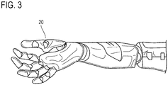
- Fig. 3 illustrates an example of a robot hand on which a sensor module of an embodiment of the present invention is to be mounted.
- a robot hand 20 has five fingers and has a form very close to that of the human hand.
- Fig. 4 illustrates a configuration of a sensor module 30 that can be mounted on the robot hand 20.
- the sensor module 30 includes a flexible body 31, five sensors 32, and sensor wiring 33, the body 31 having the shape of a glove with five fingers.
- the sensor 32 and the sensor wiring 33 are fixed to the outer surface of the body 31.
- the material of the body 31 is a material that adheres to the robot hand 20, such as silicone rubber.
- the body 31 is, simply put, a glove, so that it is possible to easily attach the sensor module 30 to the robot hand 20 and to easily remove the sensor module 30 from the robot hand 20.
- One sensor 32 is provided at the fingertip of each finger of the body 31. That is, a position on the body 31 where the sensor 32 is fixed is a position corresponding to the fingertip of the finger of the robot hand 20 in a state where the sensor module 30 has been put on the robot hand 20.
- the sensor 32 is, for example, a proximity sensor.
- the term "proximity sense” is defined as "a sense that is not in humans, and a sense felt as if the sense of touch has spread up to several centimeters above the human skin.”
- the proximity sensor is a sensor that, in a state where the robot hand has come several millimeters to tens of centimeters close to an object, detects a space distance, a relative angle, object surface characteristics, and the like.
- the proximity sensor of this example is a light-reflecting proximity sensor which includes an infrared light-emitting diode and a phototransistor to measure the space distance from the object with the amount of reflected light.
- the sensor wiring 33 includes five conductive wire sets 33b extending from five sensors 32 to a wrist portion of the body 31.
- One conductive wire set 33b is connected to one sensor 32.
- One conductive wire set 33b includes a conductive wire for a power supply of the light-emitting diode, a conductive wire for a detection signal of the phototransistor, a conductive wire for a ground (GND) of each of the light-emitting diode and the phototransistor.
- Each conductive wire has one terminal 33a at the wrist-side end.
- the sensor wiring 33 is formed by printing (e.g., screen printing) on the body 31 flattened. Forming the sensor wiring 33 by printing can lead to reduction in the manufacturing cost of the sensor wiring 33.
- the sensor 32 is fixed onto the body 31 by being soldered to a pad (hidden and invisible in Fig. 4 ) formed at the fingertip-side end of the conductive wire.
- the approach of the object can be reliably detected, whereby it is possible to avoid collision with the object and to further achieve soft contact.
- a force for gripping the object cannot be controlled using the detection signal of the proximity sensor.
- the object is a known object, by setting a predetermined gripping force in advance in the control device for the robot hand, it is possible to grip the object with the predetermined gripping force even after the contact.
- the sensor module 30 described above is a glove-type device to which the sensor 32 is attached, the sensor 32 being required for controlling the robot hand 20 that grips and operates the object. Therefore, only by attaching the sensor module 30 to the robot hand 20, the sensor 32 can be easily attached to the robot hand 20. Further, only by removing the sensor module 30 from the robot hand 20, the sensor 32 can be easily removed from the robot hand 20. In the case of replacement or repair of the sensor 32, the sensor 32 can be removed from the robot hand 20 only by removing the sensor module 30 from the robot hand 20, so that it is unnecessary to perform the disassembly operation of the robot hand 20 itself, and some other operation. In addition, a change in the type of sensor 32 can be achieved by a simple operation of replacing the sensor module 30.
- the hygiene management of the robot hand 20 is important.
- the hygiene management of the robot hand 20 can be easily performed by using the sensor module 30 as a disposable product.
- a micro-controller unit (MCU) 34 having an analog-to-digital conversion function may be placed between the sensor 32 and three terminals 33a.
- the MCU 34 is located as close as possible to the sensor 32. Digitizing the detection signal of the sensor 32 can lead to improvement in the signal quality (noise immunity) of the detection signal.
- Second to fifth embodiments will be described below, but detailed descriptions thereof will be omitted by denoting the same reference numerals to components corresponding to those of the first embodiment.
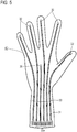
- Fig. 5 illustrates a configuration of a sensor module 40 of the second embodiment.
- the sensor module 40 has a configuration with one proximity sensor 35 added to the outer surface of a palm part of the body 31 in the sensor module 30 of the first embodiment.
- a position on the body 31 where the proximity sensor 35 is fixed is a position corresponding to the palm part of the robot hand 20 in a state where the sensor module 40 has been put on the robot hand 20.
- the proximity sensor 35 is a light-reflecting proximity sensor in this example. In a case where the proximity sensor 35 is fixed to a position on the sensor module 40 corresponding to the palm part of the robot hand 20, it is possible to control the movement of the entire robot hand 20 with respect to the object by a detection signal of the proximity sensor 35.
- Fig. 6 illustrates a configuration of a sensor module 50 of the third embodiment.
- a wireless communication device 36 is fixed to the outer surface of the wrist portion of the body 31.
- the sensor wiring 33 is connected to the wireless communication device 36.
- control device for controlling the robot hand is connected by wire to the sensor module 30, 40, but as in the third embodiment, the control device may be connected wirelessly to the sensor module 50 via the wireless communication device 36.
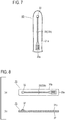
- Fig. 7 illustrates a configuration of a sensor module 60 of the fourth embodiment.
- a body 31a of the sensor module 60 has the shape of a finger cot.
- the sensor module 60 is prepared in accordance with the number of fingers and the shape of the finger of the robot hand 20.
- the sensor module 60 is put on each finger of the robot hand 20. Naturally, it is easy to remove the sensor module 60 from the finger of the robot hand 20.
- a position on the body 31a where the sensor 32 is fixed is a position corresponding to the fingertip of the finger of the robot hand 20 in a state where the sensor module 60 is mounted on the finger of the robot hand 20.
- the sensor module 60 having the shape of the finger cot may be used in accordance with the form and function of the robot hand 20.
- Fig. 8 illustrates a configuration of a sensor module 70 of the fifth embodiment.
- the sensor module 70 includes a sheet-like body 31b.
- the body 31b has an elongated rectangular shape corresponding to one finger of the robot hand 20.
- Pressure-sensitive adhesive 37 is applied onto the surface of the body 31b on the opposite side to the outer surface to which the sensor 32 is fixed.
- the sensor module 70 is bonded to each finger of the robot hand 20 with the pressure-sensitive adhesive 37. Naturally, it is easy to remove the sensor module 70 from the finger of the robot hand 20.
- a position on the body 31b where the sensor 32 is fixed is a position corresponding to the fingertip of the finger of the robot hand 20 in a state where the sensor module 70 is bonded to the finger of the robot hand 20.
- the sheet-like sensor module 70 may be used in accordance with the form and function of the robot hand 20.
- the proximity sensor 35 may be fixed to a position on the sensor module 70 corresponding to the palm part of the robot hand 20 in the same manner as in Example 2.
- the proximity sensor by disposing the proximity sensor at the position, in the sensor module, corresponding to the fingertip of the finger of the robot hand, it is possible to accurately and easily grasp the position of the object.
- the proximity sensor for example, as compared to the case of using a visual sensor that requires image processing for recognition of the object, it is possible to significantly reduce the load of signal processing.
- the sensor module it is also possible to fix two or more proximity sensors to one finger. By fixing the proximity sensors to one finger, it is possible to detect the relative movement of the object to the finger.
- the proximity sensor is not limited to the light-reflecting proximity sensor, but an ultrasonic proximity sensor may be used.
- a magnetic proximity sensor can also be used in view of the material of the object.
- the sensor 32 is not limited to the proximity sensor but may be a tactile sensor.
- the tactile sensor is a pressure sensor or the like for detecting pressure that is exerted on the fingertip by contact with the object.
- a pressure sensor may be used as the sensor 32 in view of the function of the robot hand.
- a unit made up of the proximity sensor and the pressure sensor may be used as the sensor 32.
- a pressure sensor that can be formed by printing is known, and such a pressure sensor is suitable for the sensor module of the present invention.
- the material of the body 31, 31a, 31b is not limited to silicone rubber but may be, for example, urethane rubber or cloth.
- the sensor wiring 33 may be covered using an insulating material when necessary.
- the MCU 34 for digitizing the detection signal of the sensor may be fixed to each of the sensor modules of the second to fifth embodiment in the same manner as in the first embodiment.
- the MCU 34 has a wireless communication function and the MCU 34 is installed as close to the sensor 32 as possible, the sensor wiring 33 is not required.
Landscapes
- Engineering & Computer Science (AREA)
- Robotics (AREA)
- Mechanical Engineering (AREA)
- Human Computer Interaction (AREA)
- Computer Networks & Wireless Communication (AREA)
- Physics & Mathematics (AREA)
- General Physics & Mathematics (AREA)
- Manipulator (AREA)
- Force Measurement Appropriate To Specific Purposes (AREA)
Abstract
Description
- The present invention relates to a sensor module that can be mounted on a robot hand having multiple fingers, and a robot system having the robot hand on which the sensor module is mounted.
- A robot hand having multiple fingers can make motions similar to the motions of the human's hand, as well as making a motion to hold an object with fingertips, by using a joint mechanism that bends and extends the fingers.
-
Fig. 1 illustrates a robot hand described in Patent Literature 1. A skeleton part (not illustrated) being the skeleton of the robot hand is covered with acover 11. Thecover 11 includes afinger cover part 12 and abase cover part 13. Thefinger cover part 12 covers a finger of the skeleton part, and thebase cover part 13 covers a base member of the skeleton part. -
Fig. 2(a) is a schematic view illustrating a cross-sectional structure of a fingertip of the robot hand. Apressure sensor 14 detects pressure that is exerted on afingertip portion 16 of afinger 15 of the skeleton part by an object (not illustrated) during the motion of thefinger 15. Thepressure sensor 14 is provided on the surface on apad 16a side of thefingertip portion 16. -
Fig. 2(b) illustrates a state where, at the motion of thefinger 15, thecover 11 contacts the object and is deformed, and the inner surface of thecover 11 contacts thepressure sensor 14. - Patent literature 1: Japanese Patent Application Laid-Open No.
2016-203264 - By providing a tactile sensor (e.g., pressure sensor) at the fingertip of the robot hand, it is possible to detect contact with an object to be gripped and operated, and it is further possible to grip the object with an appropriate gripping force.
- In the conventional robot hand, the tactile sensor is incorporated in the robot hand as a component of the robot hand. Therefore, for example, in the case of replacement or repair of the tactile sensor, it is necessary to perform the disassembly operation of the robot hand. In other words, it has not been easy to either attach the tactile sensor to the robot or remove the tactile sensor from the robot hand.
- An object of the present invention is to provide a sensor module that can facilitate attaching the sensor to the robot hand and removing the sensor from the robot hand, and a robot system including the sensor module.
- A sensor module of the present invention includes a flexible body and a sensor fixed to the outer surface of the body. The body is attachable to a robot hand having multiple fingers and is removable from the robot hand. The sensor is a proximity sensor or a tactile sensor. A position on the body where the sensor is fixed corresponds to a fingertip of a finger of the robot hand in a state where the sensor module is attached to the robot hand.
- According to the present invention, the sensor is fixed to the flexible body easy to attach to the robot hand and easy to remove from the robot hand. Hence it is easy to both attach the sensor to the robot hand and remove the sensor from the robot hand.
-
Fig. 1 is a perspective view of a conventional example of a robot hand; -
Fig. 2 is a sectional view of the fingertip of the robot hand, whereFig. 2(a) is a sectional view of the fingertip of the robot hand illustrated inFig. 1, and Fig. 2(b) is a sectional view of the fingertip of the robot hand in a state where a cover is deformed; -
Fig. 3 is a view illustrating an example of the robot hand; -
Fig. 4 is a view illustrating a sensor module of a first embodiment; -
Fig. 5 is a view illustrating a sensor module of a second embodiment; -
Fig. 6 is a view illustrating a sensor module of a third embodiment; -
Fig. 7 is a view illustrating a sensor module of a fourth embodiment; and -
Fig. 8 is a view illustrating a sensor module of a fifth embodiment, whereFig. 8(a) is a plan view, andFig. 8(b) is a sectional view. - Embodiments of the present invention will be described with reference to the drawings.
-
Fig. 3 illustrates an example of a robot hand on which a sensor module of an embodiment of the present invention is to be mounted. Arobot hand 20 has five fingers and has a form very close to that of the human hand. -
Fig. 4 illustrates a configuration of a sensor module 30 that can be mounted on therobot hand 20. The sensor module 30 includes aflexible body 31, fivesensors 32, andsensor wiring 33, thebody 31 having the shape of a glove with five fingers. Thesensor 32 and thesensor wiring 33 are fixed to the outer surface of thebody 31. - The material of the
body 31 is a material that adheres to therobot hand 20, such as silicone rubber. Thebody 31 is, simply put, a glove, so that it is possible to easily attach the sensor module 30 to therobot hand 20 and to easily remove the sensor module 30 from therobot hand 20. - One
sensor 32 is provided at the fingertip of each finger of thebody 31. That is, a position on thebody 31 where thesensor 32 is fixed is a position corresponding to the fingertip of the finger of therobot hand 20 in a state where the sensor module 30 has been put on therobot hand 20. - The
sensor 32 is, for example, a proximity sensor. In the present specification, the term "proximity sense" is defined as "a sense that is not in humans, and a sense felt as if the sense of touch has spread up to several centimeters above the human skin." The proximity sensor is a sensor that, in a state where the robot hand has come several millimeters to tens of centimeters close to an object, detects a space distance, a relative angle, object surface characteristics, and the like. The proximity sensor of this example is a light-reflecting proximity sensor which includes an infrared light-emitting diode and a phototransistor to measure the space distance from the object with the amount of reflected light. - The
sensor wiring 33 includes fiveconductive wire sets 33b extending from fivesensors 32 to a wrist portion of thebody 31. Oneconductive wire set 33b is connected to onesensor 32. Oneconductive wire set 33b includes a conductive wire for a power supply of the light-emitting diode, a conductive wire for a detection signal of the phototransistor, a conductive wire for a ground (GND) of each of the light-emitting diode and the phototransistor. Each conductive wire has oneterminal 33a at the wrist-side end. - The
sensor wiring 33 is formed by printing (e.g., screen printing) on thebody 31 flattened. Forming thesensor wiring 33 by printing can lead to reduction in the manufacturing cost of thesensor wiring 33. - The
sensor 32 is fixed onto thebody 31 by being soldered to a pad (hidden and invisible inFig. 4 ) formed at the fingertip-side end of the conductive wire. - In a state where the sensor module 30 configured as described above has been put on the
robot hand 20, wiring (not illustrated) of a control device, which controls the drive of therobot hand 20, is connected to theterminal 33a of thesensor wiring 33 of the sensor module 30. Thereby, therobot hand 20 is controlled in accordance with a detection signal of thesensor 32. - In this example, with the
sensor 32 being the proximity sensor that detects the distance to the object, the approach of the object can be reliably detected, whereby it is possible to avoid collision with the object and to further achieve soft contact. In this regard, after the contact with the object, for example, a force for gripping the object cannot be controlled using the detection signal of the proximity sensor. However, when the object is a known object, by setting a predetermined gripping force in advance in the control device for the robot hand, it is possible to grip the object with the predetermined gripping force even after the contact. - The sensor module 30 described above is a glove-type device to which the
sensor 32 is attached, thesensor 32 being required for controlling therobot hand 20 that grips and operates the object. Therefore, only by attaching the sensor module 30 to therobot hand 20, thesensor 32 can be easily attached to therobot hand 20. Further, only by removing the sensor module 30 from therobot hand 20, thesensor 32 can be easily removed from therobot hand 20. In the case of replacement or repair of thesensor 32, thesensor 32 can be removed from therobot hand 20 only by removing the sensor module 30 from therobot hand 20, so that it is unnecessary to perform the disassembly operation of therobot hand 20 itself, and some other operation. In addition, a change in the type ofsensor 32 can be achieved by a simple operation of replacing the sensor module 30. - For robots (or robot systems) used in the medical field and the food handling field, the hygiene management of the
robot hand 20 is important. In this regard, with the sensor module 30 having the glove-like structure to be put on therobot hand 20, the hygiene management of therobot hand 20 can be easily performed by using the sensor module 30 as a disposable product. - In the first embodiment, for each
conductive wire set 33b, a micro-controller unit (MCU) 34 having an analog-to-digital conversion function may be placed between thesensor 32 and threeterminals 33a. Preferably, theMCU 34 is located as close as possible to thesensor 32. Digitizing the detection signal of thesensor 32 can lead to improvement in the signal quality (noise immunity) of the detection signal. - Second to fifth embodiments will be described below, but detailed descriptions thereof will be omitted by denoting the same reference numerals to components corresponding to those of the first embodiment.
-
Fig. 5 illustrates a configuration of asensor module 40 of the second embodiment. Thesensor module 40 has a configuration with oneproximity sensor 35 added to the outer surface of a palm part of thebody 31 in the sensor module 30 of the first embodiment. A position on thebody 31 where theproximity sensor 35 is fixed is a position corresponding to the palm part of therobot hand 20 in a state where thesensor module 40 has been put on therobot hand 20. - The
proximity sensor 35 is a light-reflecting proximity sensor in this example. In a case where theproximity sensor 35 is fixed to a position on thesensor module 40 corresponding to the palm part of therobot hand 20, it is possible to control the movement of theentire robot hand 20 with respect to the object by a detection signal of theproximity sensor 35. -
Fig. 6 illustrates a configuration of asensor module 50 of the third embodiment. In thesensor module 50, awireless communication device 36 is fixed to the outer surface of the wrist portion of thebody 31. Thesensor wiring 33 is connected to thewireless communication device 36. - In each of the first and second embodiments, the control device for controlling the robot hand is connected by wire to the
sensor module 30, 40, but as in the third embodiment, the control device may be connected wirelessly to thesensor module 50 via thewireless communication device 36. -
Fig. 7 illustrates a configuration of asensor module 60 of the fourth embodiment. Abody 31a of thesensor module 60 has the shape of a finger cot. - The
sensor module 60 is prepared in accordance with the number of fingers and the shape of the finger of therobot hand 20. Thesensor module 60 is put on each finger of therobot hand 20. Naturally, it is easy to remove thesensor module 60 from the finger of therobot hand 20. A position on thebody 31a where thesensor 32 is fixed is a position corresponding to the fingertip of the finger of therobot hand 20 in a state where thesensor module 60 is mounted on the finger of therobot hand 20. - As thus described, the
sensor module 60 having the shape of the finger cot may be used in accordance with the form and function of therobot hand 20. -
Fig. 8 illustrates a configuration of asensor module 70 of the fifth embodiment. Thesensor module 70 includes a sheet-like body 31b. Thebody 31b has an elongated rectangular shape corresponding to one finger of therobot hand 20. Pressure-sensitive adhesive 37 is applied onto the surface of thebody 31b on the opposite side to the outer surface to which thesensor 32 is fixed. - The
sensor module 70 is bonded to each finger of therobot hand 20 with the pressure-sensitive adhesive 37. Naturally, it is easy to remove thesensor module 70 from the finger of therobot hand 20. A position on thebody 31b where thesensor 32 is fixed is a position corresponding to the fingertip of the finger of therobot hand 20 in a state where thesensor module 70 is bonded to the finger of therobot hand 20. As thus described, the sheet-like sensor module 70 may be used in accordance with the form and function of therobot hand 20. - As a modification of the
sensor module 70, it is possible to employ a configuration in which the sheet-like body 31b has the shape of a hand. Furthermore, in this modification, theproximity sensor 35 may be fixed to a position on thesensor module 70 corresponding to the palm part of therobot hand 20 in the same manner as in Example 2. - As is apparent from the embodiment, by disposing the proximity sensor at the position, in the sensor module, corresponding to the fingertip of the finger of the robot hand, it is possible to accurately and easily grasp the position of the object. By using the proximity sensor, for example, as compared to the case of using a visual sensor that requires image processing for recognition of the object, it is possible to significantly reduce the load of signal processing.
- In the sensor module, it is also possible to fix two or more proximity sensors to one finger. By fixing the proximity sensors to one finger, it is possible to detect the relative movement of the object to the finger.
- The proximity sensor is not limited to the light-reflecting proximity sensor, but an ultrasonic proximity sensor may be used. A magnetic proximity sensor can also be used in view of the material of the object.
- The
sensor 32 is not limited to the proximity sensor but may be a tactile sensor. The tactile sensor is a pressure sensor or the like for detecting pressure that is exerted on the fingertip by contact with the object. A pressure sensor may be used as thesensor 32 in view of the function of the robot hand. A unit made up of the proximity sensor and the pressure sensor may be used as thesensor 32. A pressure sensor that can be formed by printing is known, and such a pressure sensor is suitable for the sensor module of the present invention. - The material of the
body - The
sensor wiring 33 may be covered using an insulating material when necessary. - The
MCU 34 for digitizing the detection signal of the sensor may be fixed to each of the sensor modules of the second to fifth embodiment in the same manner as in the first embodiment. When theMCU 34 has a wireless communication function and theMCU 34 is installed as close to thesensor 32 as possible, thesensor wiring 33 is not required.
Claims (10)
- A sensor module comprising:a flexible body; anda sensor fixed to an outer surface of the flexible body,whereinthe flexible body is attachable to a robot hand having multiple fingers and is removable from the robot hand,the sensor is a proximity sensor or a tactile sensor, anda position on the flexible body where the sensor is fixed corresponds to a fingertip of a finger of the robot hand in a state where the sensor module is attached to the robot hand.
- The sensor module according to claim 1, wherein the flexible body has a shape of a glove.
- The sensor module according to claim 1, wherein the flexible body has a shape of a finger cot.
- The sensor module according to claim 1, wherein the flexible body has a shape of a sheet.
- The sensor module according to claim 2 or 4, wherein a proximity sensor is fixed to a position on the outer surface corresponding to a palm of the robot hand in a state where the sensor module is attached to the robot hand.
- The sensor module according to any one of claims 1 to 5, wherein when the sensor is the proximity sensor, the sensor is a light-reflecting proximity sensor.
- The sensor module according to any one of claims 1 to 6, wherein sensor wiring is formed on the outer surface.
- The sensor module according to any one of claims 1 to 6, wherein a wireless communication device is provided on the outer surface.
- A robot system comprising:a robot hand; andthe sensor module according to claim 7,whereinthe sensor module is attached to the robot hand, anda control device for the robot hand is connected by wiring to the sensor wiring.
- A robot system comprising:a robot hand; andthe sensor module according to claim 8,whereinthe sensor module is attached to the robot hand, anda control device for the robot hand is wirelessly connected to the wireless communication device.
Applications Claiming Priority (2)
| Application Number | Priority Date | Filing Date | Title |
|---|---|---|---|
| JP2018071072A JP6554202B1 (en) | 2018-04-02 | 2018-04-02 | Sensor module and robot system |
| PCT/JP2018/047750 WO2019193795A1 (en) | 2018-04-02 | 2018-12-26 | Sensor module and robot system |
Publications (2)
| Publication Number | Publication Date |
|---|---|
| EP3747605A1 true EP3747605A1 (en) | 2020-12-09 |
| EP3747605A4 EP3747605A4 (en) | 2021-05-05 |
Family
ID=67473432
Family Applications (1)
| Application Number | Title | Priority Date | Filing Date |
|---|---|---|---|
| EP18913983.5A Withdrawn EP3747605A4 (en) | 2018-04-02 | 2018-12-26 | SENSOR MODULE AND ROBOT SYSTEM |
Country Status (5)
| Country | Link |
|---|---|
| US (1) | US20200376674A1 (en) |
| EP (1) | EP3747605A4 (en) |
| JP (1) | JP6554202B1 (en) |
| CN (1) | CN112074384A (en) |
| WO (1) | WO2019193795A1 (en) |
Families Citing this family (6)
| Publication number | Priority date | Publication date | Assignee | Title |
|---|---|---|---|---|
| CN111103076A (en) * | 2019-12-18 | 2020-05-05 | 上海交通大学 | Wearable Braille recognition system, recognition method and preparation method thereof |
| JP2024059048A (en) * | 2022-10-17 | 2024-04-30 | ロボセンサー技研株式会社 | Sensor Unit |
| JP7679566B2 (en) * | 2023-04-24 | 2025-05-20 | 西武建設株式会社 | Robot hand and drone equipped with same |
| US12179341B2 (en) * | 2023-07-28 | 2024-12-31 | Google Llc | Simulation manipulator |
| CN119681963B (en) * | 2024-12-30 | 2025-09-09 | 南昌大学 | Self-adaptive grabbing-oriented proximity sense and touch sense cooperative mechanical gripper sensing system |
| CN119871493B (en) * | 2025-03-05 | 2025-12-23 | 戴盟(深圳)机器人科技有限公司 | Mechanical glove with visual touch sensor, operation method and control system |
Family Cites Families (20)
| Publication number | Priority date | Publication date | Assignee | Title |
|---|---|---|---|---|
| US5413611A (en) * | 1992-07-21 | 1995-05-09 | Mcp Services, Inc. | Computerized electronic prosthesis apparatus and method |
| JPH10249768A (en) * | 1997-03-12 | 1998-09-22 | Tokai Rubber Ind Ltd | Force sensor |
| US6247738B1 (en) * | 1998-01-20 | 2001-06-19 | Daum Gmbh | Robot hand |
| JP3144420B1 (en) * | 1999-10-21 | 2001-03-12 | オムロン株式会社 | Artificial haptic device, artificial skin and robot using the haptic device |
| US6996456B2 (en) * | 2002-10-21 | 2006-02-07 | Fsi International, Inc. | Robot with tactile sensor device |
| US7296835B2 (en) * | 2005-08-11 | 2007-11-20 | Anybots, Inc. | Robotic hand and arm apparatus |
| JP5416904B2 (en) * | 2008-02-12 | 2014-02-12 | 株式会社東芝 | Pressure sensor and robot hand system |
| JP2010158754A (en) * | 2009-01-09 | 2010-07-22 | Nippon Telegr & Teleph Corp <Ntt> | Covering device for robot hand |
| US8662552B2 (en) * | 2010-02-23 | 2014-03-04 | Massachusetts Institute Of Technology | Dexterous and compliant robotic finger |
| JP2011224695A (en) * | 2010-04-19 | 2011-11-10 | Toyota Motor Corp | System for controlling holding of robot, and robot |
| JP5859837B2 (en) * | 2011-12-15 | 2016-02-16 | 株式会社日立製作所 | Robot apparatus and sensor state determination method |
| US9120233B2 (en) * | 2012-05-31 | 2015-09-01 | Toyota Motor Engineering & Manufacturing North America, Inc. | Non-contact optical distance and tactile sensing system and method |
| US9149933B2 (en) * | 2013-02-07 | 2015-10-06 | GM Global Technology Operations LLC | Grasp assist device with shared tendon actuator assembly |
| JP5835276B2 (en) * | 2013-06-24 | 2015-12-24 | 株式会社安川電機 | Robot, robot manufacturing method and bag |
| RU2743044C1 (en) * | 2014-02-20 | 2021-02-12 | Марк ОЛЕЙНИК | Robotic kitchen system |
| JP2016052697A (en) * | 2014-09-03 | 2016-04-14 | インターマン株式会社 | Humanoid robot |
| CN107077207B (en) * | 2014-10-17 | 2020-10-27 | 雅马哈株式会社 | data gloves |
| JP2016203264A (en) * | 2015-04-15 | 2016-12-08 | 株式会社豊田自動織機 | Robot hand |
| JP2016218063A (en) * | 2015-05-19 | 2016-12-22 | 日本精工株式会社 | Proximity sensor |
| JP6471812B2 (en) * | 2016-01-29 | 2019-02-20 | 株式会社リコー | Pressure-sensitive sensor, gripping device, and robot |
-
2018
- 2018-04-02 JP JP2018071072A patent/JP6554202B1/en active Active
- 2018-12-26 EP EP18913983.5A patent/EP3747605A4/en not_active Withdrawn
- 2018-12-26 US US16/970,695 patent/US20200376674A1/en not_active Abandoned
- 2018-12-26 CN CN201880090667.1A patent/CN112074384A/en active Pending
- 2018-12-26 WO PCT/JP2018/047750 patent/WO2019193795A1/en not_active Ceased
Also Published As
| Publication number | Publication date |
|---|---|
| JP2019181578A (en) | 2019-10-24 |
| EP3747605A4 (en) | 2021-05-05 |
| JP6554202B1 (en) | 2019-07-31 |
| CN112074384A (en) | 2020-12-11 |
| WO2019193795A1 (en) | 2019-10-10 |
| US20200376674A1 (en) | 2020-12-03 |
Similar Documents
| Publication | Publication Date | Title |
|---|---|---|
| US20200376674A1 (en) | Sensor module and robot system | |
| KR101383421B1 (en) | Upper extremity rehabilitation robot for assistance meals | |
| Dahiya et al. | Tactile sensing—from humans to humanoids | |
| JP7149277B2 (en) | Hand mechanism and grasping system | |
| Mukai et al. | Development of a nursing-care assistant robot RIBA that can lift a human in its arms | |
| CN102037340A (en) | Complex sensor and robot hand | |
| TWI696953B (en) | Information reading device | |
| US20160136822A1 (en) | Robotic finger structure | |
| US8537036B2 (en) | Tongue based control device for transferring keyboard commands | |
| JP5108485B2 (en) | Method for acting on tactile sense, tactile device for realizing the same, and bending-variable mechanism | |
| US20210072762A1 (en) | Motion detecting device | |
| CN117921721A (en) | Flexible sensor system applied to smart hand touch control of humanoid robot | |
| US12032739B2 (en) | Virtual reality wearable system | |
| KR101383450B1 (en) | Upper extremity rehabilitation robot control method for meal assistance | |
| US20250044872A1 (en) | Operation device and operation system | |
| KR101835097B1 (en) | Wearable interface device using piezoelectric element | |
| Wang et al. | Design and performance of a haptic data acquisition glove | |
| JP2004330370A (en) | Tactile sensor for robot hand | |
| Premarathna et al. | Haptic feedback system for an artificial prosthetic hand for object grasping and slip detection: A preliminary study | |
| Suwanratchatamanee et al. | Balance control of robot and human-robot interaction with haptic sensing foots | |
| CN114831849A (en) | Upper limb exoskeleton system and method based on flexible strain sensor drive | |
| JP7468785B2 (en) | Proximity Sensors and Controllers | |
| CN215494930U (en) | Body sensing glove with fingerstall capable of being shifted | |
| EP4404879B1 (en) | Non-invasive tongue based interface | |
| CN117901165A (en) | Variable-rigidity manipulator based on flexible finger deformation |
Legal Events
| Date | Code | Title | Description |
|---|---|---|---|
| STAA | Information on the status of an ep patent application or granted ep patent |
Free format text: STATUS: THE INTERNATIONAL PUBLICATION HAS BEEN MADE |
|
| PUAI | Public reference made under article 153(3) epc to a published international application that has entered the european phase |
Free format text: ORIGINAL CODE: 0009012 |
|
| STAA | Information on the status of an ep patent application or granted ep patent |
Free format text: STATUS: REQUEST FOR EXAMINATION WAS MADE |
|
| 17P | Request for examination filed |
Effective date: 20200901 |
|
| AK | Designated contracting states |
Kind code of ref document: A1 Designated state(s): AL AT BE BG CH CY CZ DE DK EE ES FI FR GB GR HR HU IE IS IT LI LT LU LV MC MK MT NL NO PL PT RO RS SE SI SK SM TR |
|
| AX | Request for extension of the european patent |
Extension state: BA ME |
|
| A4 | Supplementary search report drawn up and despatched |
Effective date: 20210401 |
|
| RIC1 | Information provided on ipc code assigned before grant |
Ipc: B25J 15/08 20060101AFI20210326BHEP Ipc: B25J 19/02 20060101ALI20210326BHEP Ipc: G01L 5/00 20060101ALI20210326BHEP Ipc: B25J 13/08 20060101ALI20210326BHEP |
|
| DAV | Request for validation of the european patent (deleted) | ||
| DAX | Request for extension of the european patent (deleted) | ||
| STAA | Information on the status of an ep patent application or granted ep patent |
Free format text: STATUS: EXAMINATION IS IN PROGRESS |
|
| 17Q | First examination report despatched |
Effective date: 20220120 |
|
| GRAP | Despatch of communication of intention to grant a patent |
Free format text: ORIGINAL CODE: EPIDOSNIGR1 |
|
| STAA | Information on the status of an ep patent application or granted ep patent |
Free format text: STATUS: GRANT OF PATENT IS INTENDED |
|
| INTG | Intention to grant announced |
Effective date: 20220719 |
|
| STAA | Information on the status of an ep patent application or granted ep patent |
Free format text: STATUS: THE APPLICATION IS DEEMED TO BE WITHDRAWN |
|
| 18D | Application deemed to be withdrawn |
Effective date: 20221130 |