EP3747601A1 - Machining apparatus and machining method - Google Patents
Machining apparatus and machining method Download PDFInfo
- Publication number
- EP3747601A1 EP3747601A1 EP19746984.4A EP19746984A EP3747601A1 EP 3747601 A1 EP3747601 A1 EP 3747601A1 EP 19746984 A EP19746984 A EP 19746984A EP 3747601 A1 EP3747601 A1 EP 3747601A1
- Authority
- EP
- European Patent Office
- Prior art keywords
- pressure
- pressure water
- abrasive grains
- pipe
- abrasive
- Prior art date
- Legal status (The legal status is an assumption and is not a legal conclusion. Google has not performed a legal analysis and makes no representation as to the accuracy of the status listed.)
- Withdrawn
Links
Images



Classifications
-
- B—PERFORMING OPERATIONS; TRANSPORTING
- B24—GRINDING; POLISHING
- B24C—ABRASIVE OR RELATED BLASTING WITH PARTICULATE MATERIAL
- B24C5/00—Devices or accessories for generating abrasive blasts
- B24C5/02—Blast guns, e.g. for generating high velocity abrasive fluid jets for cutting materials
-
- B—PERFORMING OPERATIONS; TRANSPORTING
- B24—GRINDING; POLISHING
- B24C—ABRASIVE OR RELATED BLASTING WITH PARTICULATE MATERIAL
- B24C5/00—Devices or accessories for generating abrasive blasts
-
- B—PERFORMING OPERATIONS; TRANSPORTING
- B24—GRINDING; POLISHING
- B24C—ABRASIVE OR RELATED BLASTING WITH PARTICULATE MATERIAL
- B24C7/00—Equipment for feeding abrasive material; Controlling the flowability, constitution, or other physical characteristics of abrasive blasts
-
- B—PERFORMING OPERATIONS; TRANSPORTING
- B24—GRINDING; POLISHING
- B24C—ABRASIVE OR RELATED BLASTING WITH PARTICULATE MATERIAL
- B24C9/00—Appurtenances of abrasive blasting machines or devices, e.g. working chambers, arrangements for handling used abrasive material
Definitions
- the present invention relates to a machining apparatus and a machining method.
- machining apparatuses there is an apparatus which vigorously injects high-pressure water mixed with an abrasive from a nozzle to cut or machine an object.
- PTL 1 discloses a cutting device using an abrasive water jet which mixes an abrasive into ultrahigh-pressure jet water.
- the abrasive introduced from a supply portion is mixed with the ultrahigh-pressure jet water inside the supply portion.
- the abrasive When the abrasive is abrasive grains, the abrasive grains may be clogged inside the supply portion. When the abrasive grains are clogged inside the supply portion, a supply amount of the abrasive grains decreases, and machining ability decreases.
- the cutting device disclosed in PTL 1 cannot detect clogging of the abrasive grains.
- An object of the present invention is to provide a machining apparatus and a machining method capable of detecting the clogging of abrasive grains in consideration of the above-described problems.
- a machining apparatus including: a high-pressure water pipe through which high-pressure water is supplied; an abrasive grain pipe through which abrasive grains are supplied; an injection unit which includes a high-pressure water introduction portion into which the high-pressure water is introduced, an abrasive grain introduction portion into which the abrasive grains are introduced, a mixing portion in which the high-pressure water and the abrasive grains are mixed with each other, and a nozzle which injects the high-pressure water having the mixed abrasive grains to an object to be machined; and a detection unit which measures a pressure inside the abrasive grain pipe and detects that the pressure is lower than a lower threshold value.
- the machining apparatus detects that the measured pressure is lower than the lower threshold value. Accordingly, the machining apparatus can detect that the abrasive grains are clogged on at least a downstream side of a pressure measurement location. Therefore, the machining apparatus can detect the clogging of the abrasive grains.
- the detection unit further detects that the pressure is higher than an upper threshold value.
- the detection unit specifies that an abnormality is present on an upstream side of a pressure measurement location by the detection unit in a case where the pressure is lower than the lower threshold value.
- the machining apparatus of according to any one of the first to third aspects further includes a partition pipe which separates a first space extending in one direction from the high-pressure water introduction portion to the nozzle and a second space around the first space from each other, inside the mixing portion and includes an opening on an introduction straight line extending in an introduction direction of the abrasive grains from the abrasive grain introduction portion; and an exhaust portion which is provided at a position facing the abrasive grain introduction portion across the first space and exhausts air inside the second space.
- a partition pipe which separates a first space extending in one direction from the high-pressure water introduction portion to the nozzle and a second space around the first space from each other, inside the mixing portion and includes an opening on an introduction straight line extending in an introduction direction of the abrasive grains from the abrasive grain introduction portion; and an exhaust portion which is provided at a position facing the abrasive grain introduction portion across the first space and exhausts air inside the second space.
- a machining apparatus including: a high-pressure water pipe through which high-pressure water is supplied; an abrasive grain pipe through which abrasive grains are supplied; an injection unit which includes a high-pressure water introduction portion into which the high-pressure water is introduced, an abrasive grain introduction portion into which the abrasive grains are introduced, a mixing portion in which the high-pressure water and the abrasive grains are mixed with each other, and a nozzle which injects the high-pressure water having the mixed abrasive grains to an object to be machined; and a partition pipe which separates a first space extending in one direction from the high-pressure water introduction portion to the nozzle and a second space around the first space from each other, inside the mixing portion and includes an opening on an introduction straight line extending in an introduction direction of the abrasive grains from the abrasive grain introduction portion; and an exhaust portion which is provided at a position facing the abrasive grain introduction portion across
- the exhaust portion is provided at the position facing the abrasive grain introduction portion across the first space and exhausts the air inside the second space. Therefore, the machining apparatus can keep a flow rate of the abrasive grains in the injection unit large. Accordingly, it is possible to suppress the clogging of the abrasive grains.
- a machining method including: a step of measuring a pressure inside an abrasive grain pipe of a machining apparatus including a high-pressure water pipe through which high-pressure water is supplied, the abrasive grain pipe through which abrasive grains are supplied, and a nozzle which is connected to the high-pressure water pipe and the abrasive grain pipe and injects the high-pressure water mixed with the abrasive grains to an object to be machined; and a step of detecting that the pressure is lower than a lower threshold value.
- the machining method detects that the measured pressure is lower than the lower threshold value. Accordingly, the machining method can detect that the abrasive grains are clogged on at least a downstream side of a pressure measurement location. Therefore, the machining method can detect the clogging of the abrasive grains.
- a machining apparatus 100 of the present embodiment is a cutting apparatus using an abrasive water jet and cuts an object to be machined OBJ.
- the machining apparatus 100 includes a high-pressure water pipe 10, an abrasive grain pipe 20, an injection unit 30, a detection unit 40, a high-pressure pump 50, and a hopper 60.
- the machining apparatus 100 injects high-pressure mixed water MH containing abrasive grains AB to the object to be machined OBJ.
- the high-pressure water pipe 10 connects the high-pressure pump 50 and the injection unit 30 to each other.
- the high-pressure pump 50 pressurizes water into high-pressure water WH and supplies the high-pressure water WH to the injection unit 30 via the high-pressure water pipe 10.
- the high-pressure water WH can be supplied to the injection unit 30 through the high-pressure water pipe 10.
- the abrasive grain pipe 20 connects a lower portion of the hopper 60 and the injection unit 30 to each other.
- An inside of the hopper 60 is filled with the abrasive grains AB.
- the abrasive grains AB are supplied into the hopper 60 from an opening on an upper portion of the hopper 60 by another device or an operator.
- the abrasive grains AB located in a lower portion of the hopper 60 are pressurized by the gravity and extruded to the abrasive grain pipe 20 connected to the lower portion of the hopper 60.
- the hopper 60 supplies the extruded abrasive grains AB to the injection unit 30 via the abrasive grain pipe 20.
- the abrasive grains AB can be supplied to the injection unit 30 through the abrasive grain pipe 20.
- the abrasive grain pipe 20 has a main pipe 20A and a branch pipe 20B.
- the main pipe 20A extends from the hopper 60 toward the injection unit 30.
- the branch pipe 20B branches off from the main pipe 20A in a middle of the main pipe 20A.
- the injection unit 30 mixes the supplied high-pressure water WH with the abrasive grains AB inside the injection unit 30 to inject the high-pressure mixed water MH.
- the detection unit 40 measures a pressure PM inside the abrasive grain pipe 20 at a measurement location, detects that the pressure PM is lower than a lower threshold value, and further detects that the pressure PM is higher than the upper threshold value.
- the injection unit 30 includes a high-pressure water introduction portion 31, an abrasive grain introduction portion 32, an orifice 34, a chamber 35 (mixing portion), and a nozzle 36.
- the chamber 35 is a pressure vessel having a substantially hollow cylindrical shape extending in an axis AX direction with an axis AX as a cylindrical axis.
- the chamber 35 is sealed except for various openings, and a pressure inside the chamber 35 can be a low pressure by closing the various openings.
- the high-pressure water WH introduced from the high-pressure water introduction portion 31 and the abrasive grains AB introduced from the abrasive grain introduction portion 32 are mixed with each other in a space between the orifice 34 and a lower surface of the chamber 35, and thus, become the high-pressure mixed water MH.
- the high-pressure water introduction portion 31 includes an opening which is provided on an upper surface of the chamber 35 and has the axis AX as a center.
- the introduced high-pressure water WH is supplied to the orifice 34 via the high-pressure water introduction portion 31.
- the abrasive grain introduction portion 32 is provided in an opening on an upper portion of an outer periphery of the chamber 35. By connecting the abrasive grain pipe 20 to the abrasive grain introduction portion 32, the abrasive grains AB are introduced from the abrasive grain introduction portion 32 into the injection unit 30.
- the orifice 34 has a through hole 34H which extends from the high-pressure water introduction portion 31 toward the nozzle 36 about the axis AX.
- a base end of the orifice 34 is connected to the high-pressure water introduction portion 31.
- a tip of the orifice 34 is directed toward the nozzle 36.
- the through hole 34H on a tip side of the orifice 34 faces the nozzle 36. The tip of the orifice 34 and the nozzle 36 are separated from each other across a space.
- the through hole 34H is a hole which opens from a base end side of the orifice 34 toward a tip side of the orifice 34.
- the through hole 34H may be a hole of an inner diameter decreases from the base end side of the orifice 34 toward the tip side of the orifice 34.
- the through hole 34H may be a small-diameter hole which opens to have a simply fixed hole diameter from the base end side of the orifice 34 toward the tip side of the orifice 34.
- the orifice 34 is made of a hard material such as diamond or ruby to suppress wear. As a result, the orifice 34 injects the high-pressure water introduced into the high-pressure water introduction portion 31 toward the nozzle 36 from the tip side of the orifice 34.
- the nozzle 36 protrudes downward from an opening on the lower surface of the chamber 35.
- the nozzle 36 extends toward a tip which protrudes from a base end on a lower surface side of the chamber 35. An upper end of the nozzle 36 is connected to the opening on the lower surface of the chamber 35.
- the nozzle 36 has a nozzle hole 36H which penetrates from an upper end toward a lower end about the axis AX.
- the nozzle 36 has a tubular shape in which the nozzle hole 36H generally has a constant diameter from a base end to a tip without changing an inner diameter of the nozzle hole 36H.
- the nozzle hole 36H has a certain length, and thus, has a function of rectifying the high-pressure mixed water MH to make the high-pressure mixed water to a narrowed flow which is not diffused. Thereby, the nozzle 36 injects the narrowed high-pressure mixed water MH toward the object to be machined OBJ from the tip of the nozzle 36.
- the high-pressure water WH is injected from the orifice 34 at a high pressure. Therefore, the high-pressure mixed water MH is also injected from the nozzle 36 at a high pressure without a change in pressure.
- the detection unit 40 includes a measurement unit 41 and a determination unit 42.
- the measurement unit 41 measures the pressure PM inside the abrasive grain pipe 20.
- the measurement unit 41 is connected to a branch end of the branch pipe 20B. For this reason, the measurement unit 41 measures the pressure PM inside the branch pipe 20B at the branch end of the branch pipe 20B which is a measurement location.
- the measurement unit 41 provides the measured pressure PM to the determination unit 42.
- the determination unit 42 detects that the obtained pressure PM is small. Specifically, the determination unit 42 compares the obtained pressure PM with a preset lower threshold value PL. Then, in a case where the pressure PM is lower than the lower threshold value PL, the determination unit 42 detects the intention.
- the determination unit 42 detects that the obtained pressure PM is large. Specifically, the determination unit 42 further compares the pressure PM with a preset upper threshold value PH. Then, in a case where the obtained pressure PM is higher than the upper threshold value PH, the determination unit 42 detects the intention.
- a lower limit and an upper limit of the pressure PM when a desired machining ability is obtained are set, respectively.
- the lower limit value and the upper limit value of the pressure PM at which a desired machining ability can be obtained are determined in advance by experience, results, experiments, or the like.
- the measurement unit 41 is a Bourdon tube pressure gauge, and as illustrated in Fig. 3 , sets a pressure at the time of the atmospheric pressure to 0 kPa and measures a pressure difference from the atmospheric pressure as the pressure.
- -50 kPa is set as the upper threshold value PH
- -70 kPa is set as the lower threshold value PL.
- the detection unit 40 may immediately output a command to stop a supply of the high-pressure water to the high-pressure pump 50.
- the detection unit 40 may output a command to a high-pressure valve 37 which is provided immediately before the high-pressure water introduction portion 31 in the middle of the high-pressure water pipe 10 and may control the high-pressure valve so that the high-pressure valve is blocked immediately after the detection.
- the machining apparatus 100 supplies the high-pressure water WH from the high-pressure water pipe 10 and the abrasive grains AB from the abrasive grain pipe 20 to the injection unit 30, respectively.
- the high-pressure water WH and the abrasive grains AB introduced into the injection unit 30 are mixed with each other inside the chamber 35 and become the high-pressure mixed water MH.
- the machining apparatus 100 injects the mixed high-pressure mixed water MH toward the object to be machined OBJ from the tip of the nozzle 36.
- the detection unit 40 measures the pressure PM inside the abrasive grain pipe 20 and detects that the pressure PM is lower than the lower threshold value PL. Meanwhile, in a case where the pressure PM is higher than the upper threshold value PH, the detection unit 40 detects the intention.
- the detection unit 40 measures the pressure PM inside the abrasive grain pipe 20.
- the hopper 60 supplies the extruded abrasive grains AB to the injection unit 30 via the abrasive grain pipe 20. Therefore, The pressure in the abrasive grain pipe 20 at least at the upstream end of the abrasive grain pipe 20 is higher than the downstream end connected to the injection part 30 due to pressure loss in the pipe, but is lower than the atmospheric pressure.
- a pressure inside the abrasive grain pipe 20 in at least a downstream end of the abrasive grain pipe 20 is at least lower than the atmospheric pressure.
- the pressure PM is lower than that when the abrasive grains AB are not clogged. The same applies to clogging in the hopper 60.
- the detection unit 40 detects that the measured pressure is lower than the lower threshold value PL, it is possible to detect that the abrasive grains AB are clogged on the upstream side (including the hopper 60) of the branch pipe 20B.
- the pressure PM is higher than that when the abrasive grains AB are not clogged.
- the detection unit 40 detects that the measured pressure is higher than the upper threshold value PH, it is possible to detect that the abrasive grains AB are clogged on the downstream side (including the nozzle 36) of the branch pipe 20B.
- the machining apparatus 100 can detect the clogging of the abrasive grains AB.
- the machining apparatus 100 using the abrasive water jet as in the present embodiment can vigorously inject the high-pressure water mixed with abrasive grains AB from a nozzle to perform trimming (trimming machining). Further, in general, the machining apparatus 100 using the abrasive water jet as in the present embodiment is usually used for cutting a hard-to-cut material, and, for example, can perform trimming (trimming machining) of a wing skin.
- the abrasive grains AB are mixed in order to increase power of the abrasive water jet, and an abrasive such as SiC or Al 2 O 3 having a particle size of about several hundred of ⁇ m is used in many cases.
- vacuum transport performed by an aspirator using the Venturi effect of a water jet is often used as in the machining apparatus 100 of the present embodiment.
- the reason for using the vacuum transport performed by an aspirator is that there is no need to use a new power for transporting the abrasive grains, and the apparatus can be simplified.
- the pressure of the jet may temporarily decrease. In this state, not only does a "sharpness" of the trim become poor and cutting quality sharply decreases, but also the cutting is impossible if a pressure decrease time of the jet is long.
- the abrasive grains AB have a sharp shape in order to improve cutting performance and quality, and because of this shape, fluidity is poor and the clogging is likely to occur essentially.
- the detection unit 40 when the detection unit 40 detects that the pressure PM is higher than the upper threshold value PH, the detection unit 40 can detect the blockage on the downstream side of the detection unit 4.
- the blockage by the abrasive grains AB may occur not only on a downstream side than the branch pipe 20B, but also at a position XH on an upstream side of the branch pipe 20B.
- the detection unit 40 not only detects that the pressure PM is higher than the upper threshold value PH, but also detects that the pressure PM is lower than the lower threshold value PL.
- the detection unit 40 determines that the pressure PM is not in a range (normal range) in which the pressure PM is the lower threshold value PL or more and the upper threshold value PH or less, and the detection unit 40 determines that the pressure PM is in a range lower than the lower threshold value PL or in a range (abnormal range) more than the upper threshold value PH.
- the pressure in the abrasive grain pipe 20 fluctuates according to a pressure fluctuation of a high-pressure pump, a water temperature which determines the negative pressure of the Venturi effect, and flow conditions of the abrasive grains AB. Therefore, it is necessary to determine a range which is not abnormal.
- the upper threshold value PH is set to -50 kPa and the lower threshold value PL is set to -70 kPa, it is possible to cope with the fluctuation.
- This value may vary depending on various conditions.
- the detection unit 40 determines whether there is a blockage on a downstream side of the pressure measurement location (branch pipe 20B) by the detection unit 40.
- at least one of the blockage of the abrasive grain pipe 20 and the blockage of the injection unit 30 occurs.
- the abrasive grain pipe 20 is blocked, the flows of the abrasive grains AB are stopped as described above.
- the injection unit 30 is blocked, the jet injected from the machining apparatus 100 stops.
- the machining apparatus 100 of the present embodiment can detect the clogging of the abrasive grains AB. Further, it is possible to detect whether the clogged location of the abrasive grains AB is the upstream side or the downstream side of the branch pipe 20B which is the pressure detection location of the detection unit 40. For this reason, it is possible to cope before the cut surface is rough or cannot be cut, and thus, an impact is extremely large in terms of cost and a delivery date.
- the detection unit 40 detects that the pressure PM is in the range lower than the lower threshold value PL or in the range (abnormal range) higher than the upper threshold value PH.
- the detection unit 40 may separately detect that the pressure PM is in the range (abnormal range (I)) lower than the lower threshold value PL and the pressure PM is in the range higher than the upper threshold value PH (abnormal range (II).)
- the detection unit 40 may specify that there is an abnormality (blockage) on the upstream side of the pressure measurement location by the detection unit 40, and when the pressure PM is in the abnormal range (II), the detection unit 40 may specify that there is an abnormality (blockage) on the downstream side of the pressure measurement location by the detection unit 40.
- a machining apparatus 200 of the present embodiment is basically the same as that of the first embodiment, but is different from that of the first embodiment in that a vacuum pump is provided. Moreover, constitutions of injection units are different from each other.
- the machining apparatus 200 includes the high-pressure water pipe 10, the abrasive grain pipe 20, an injection unit 230, the detection unit 40, the high-pressure pump 50, and the hopper 60. As illustrated in Fig. 6 , the machining apparatus 200 further includes a vacuum pump 80.
- the injection unit 230 mixes the supplied high-pressure water WH with the abrasive grains AB inside the injection unit 30 to inject the high-pressure mixed water MH.
- the injection unit 230 include the high-pressure water introduction portion 31, the abrasive grain introduction portion 32, an exhaust portion 33, the orifice 34, a chamber 235 (mixing portion), the nozzle 36, and a partition pipe 70.
- the partition pipe 70 is provided inside the chamber 235.
- the partition pipe 70 separates a first space SP1 extending in one direction from the high-pressure water introduction portion 31 to the nozzle 36 and the second space SP2 around the first space SP1.
- the partition pipe 70 has an opening 70H on an introduction straight line Li extending in introduction directions of the abrasive grains AB from the abrasive grain introduction portion 32.
- the exhaust portion 33 is provided at a position facing the abrasive grain introduction portion 32 across the first space SP1. This position is best.
- the second space SP2 may be provided anywhere as long as it is a place where the second space SP2 can be exhausted and does not affect the flow of abrasive grains passing through the opening 70H.
- a vacuum pump 80 is connected to the exhaust portion 33. The vacuum pump 80 exhausts gas in the second space SP2 from the exhaust portion 33.
- a pressure inside the chamber 235 is reduced by the vacuum pump 80. Therefore, most of the abrasive grains AB introduced from the abrasive grain introduction portion 32 are accelerated in the direction of the introduction straight line Li so as to be sucked into the chamber 235. Moreover, most of the accelerated abrasive grains AB rush into the opening 70H due to inertial motion, are mixed with the high-pressure water WH to be the high-pressure mixed water MH, and are injected from the nozzle 36.
- the negative pressure formed by the Venturi effect has many small fluctuations. Accordingly, when the abrasive grains AB are transported into the injection unit using the Venturi effect as in the first embodiment, a transport amount of the abrasive grains AB may be unstable. When the transport amount of the abrasive grains AB is unstable, it is difficult to keep a transport flow rate of the abrasive grains AB into the injection unit high.
- the negative pressure due to the Venturi effect of the high-pressure jet is small.
- the vacuum pump 80 is separately provided and the abrasive grains AB are transported by decompressed air, it is possible to increase the flow rate.
- the air inside the second space SP2 is exhausted using an independent dedicated system for introducing the abrasive grains, and in the machining apparatus 200, the separate vacuum pump 80 is provided to transport the abrasive grains AB by decompressed air.
- the partition pipe 70 is provided inside the chamber 235.
- the exhaust portion 33 is provided at the position facing the abrasive grain introduction portion 32 across the first space SP1. Accordingly, solid (abrasive grain) - gas (air) separation can be performed inside the injection unit 230.
- the partition pipe 70 since the partition pipe 70 is provided, the flows of the abrasive grains AB on the introduction straight line Li are not easily obstructed. As a result, the abrasive grains AB are introduced from the abrasive grain introduction portion 32 into the first space SP1 through the opening 70H.
- the machining apparatus 100 measures the pressure inside the abrasive grain pipe 20 (ST10: a step of measuring the pressure).
- the machining apparatus 100 compares the obtained pressure PM with the preset lower threshold value PL (ST20: a step of comparing with the lower threshold value).
- the machining apparatus 100 compares the pressure PM with the preset upper threshold value PH (ST30: a step of comparing with the upper threshold value).
- the process returns to ST10, and the pressure inside the abrasive grain pipe 20 is measured again.
- the machining apparatus 100 detects that pressure PM is out of the range (the pressure PM is lower than the lower threshold value PL or higher than the upper threshold value PH).
- the detection unit 40 when detecting that the obtained pressure PM is lower than the lower threshold value PL or detecting that the pressure PM is higher than the upper threshold value PH, the detection unit 40 immediately supplies high-pressure water to the high-pressure pump 50.
- a command to stop is output (ST50: output step).
- the detection unit 40 may output a command to the high-pressure valve 37 which is provided immediately before the high-pressure water introduction portion 31 in the middle of the high-pressure water pipe 10 as illustrated in Fig. 2 .
- the high-pressure valve 37 receiving the command stops the injection of the high-pressure water WH, and thus, the machining apparatus 100 stops the injection of the high-pressure mixed water MH.
- Each step of the present machining method is performed by the machining apparatus.
- at least one of steps ST10 to ST50 may be performed by an operator.
- the machining apparatus compares the obtained pressure PM with the lower threshold value PL and also compares the obtained pressure PM with the upper threshold value PH.
- the machining apparatus detects only that the pressure PM is lower than the lower threshold value, and does not detect that the pressure PM is higher than the upper threshold value PH.
- the machining apparatus and the machining method perform cutting of the object to be machined OBJ, but may perform machining of the object to be machined OBJ even without cutting the object to be machined OBJ.
Landscapes
- Engineering & Computer Science (AREA)
- Mechanical Engineering (AREA)
- Perforating, Stamping-Out Or Severing By Means Other Than Cutting (AREA)
- Finish Polishing, Edge Sharpening, And Grinding By Specific Grinding Devices (AREA)
Abstract
Description
- The present invention relates to a machining apparatus and a machining method.
- This application claims the priority of Japanese Patent Application No.
2018-014975 - As one of machining apparatuses, there is an apparatus which vigorously injects high-pressure water mixed with an abrasive from a nozzle to cut or machine an object.
- For example, PTL 1 discloses a cutting device using an abrasive water jet which mixes an abrasive into ultrahigh-pressure jet water.
- [PTL 1] Japanese Unexamined Utility Model Registration Application Publication No.
02-19466 - In the cutting device disclosed in PTL 1, the abrasive introduced from a supply portion is mixed with the ultrahigh-pressure jet water inside the supply portion.
- When the abrasive is abrasive grains, the abrasive grains may be clogged inside the supply portion. When the abrasive grains are clogged inside the supply portion, a supply amount of the abrasive grains decreases, and machining ability decreases.
- However, the cutting device disclosed in PTL 1 cannot detect clogging of the abrasive grains.
- An object of the present invention is to provide a machining apparatus and a machining method capable of detecting the clogging of abrasive grains in consideration of the above-described problems.
- According to a first aspect, there is provided a machining apparatus including: a high-pressure water pipe through which high-pressure water is supplied; an abrasive grain pipe through which abrasive grains are supplied; an injection unit which includes a high-pressure water introduction portion into which the high-pressure water is introduced, an abrasive grain introduction portion into which the abrasive grains are introduced, a mixing portion in which the high-pressure water and the abrasive grains are mixed with each other, and a nozzle which injects the high-pressure water having the mixed abrasive grains to an object to be machined; and a detection unit which measures a pressure inside the abrasive grain pipe and detects that the pressure is lower than a lower threshold value.
- According to this aspect, the machining apparatus detects that the measured pressure is lower than the lower threshold value. Accordingly, the machining apparatus can detect that the abrasive grains are clogged on at least a downstream side of a pressure measurement location. Therefore, the machining apparatus can detect the clogging of the abrasive grains.
- Moreover, according to a second aspect, in the machining apparatus according to the first aspect, the detection unit further detects that the pressure is higher than an upper threshold value.
- Further, according to a third aspect, in the machining apparatus according to the first or second aspect, the detection unit specifies that an abnormality is present on an upstream side of a pressure measurement location by the detection unit in a case where the pressure is lower than the lower threshold value.
- In addition, according to a fourth aspect, the machining apparatus of according to any one of the first to third aspects further includes a partition pipe which separates a first space extending in one direction from the high-pressure water introduction portion to the nozzle and a second space around the first space from each other, inside the mixing portion and includes an opening on an introduction straight line extending in an introduction direction of the abrasive grains from the abrasive grain introduction portion; and
an exhaust portion which is provided at a position facing the abrasive grain introduction portion across the first space and exhausts air inside the second space. - Further, according to a fifth aspect, there is provided a machining apparatus including: a high-pressure water pipe through which high-pressure water is supplied; an abrasive grain pipe through which abrasive grains are supplied; an injection unit which includes a high-pressure water introduction portion into which the high-pressure water is introduced, an abrasive grain introduction portion into which the abrasive grains are introduced, a mixing portion in which the high-pressure water and the abrasive grains are mixed with each other, and a nozzle which injects the high-pressure water having the mixed abrasive grains to an object to be machined; and a partition pipe which separates a first space extending in one direction from the high-pressure water introduction portion to the nozzle and a second space around the first space from each other, inside the mixing portion and includes an opening on an introduction straight line extending in an introduction direction of the abrasive grains from the abrasive grain introduction portion; and an exhaust portion which is provided at a position facing the abrasive grain introduction portion across the first space and exhausts air inside the second space.
- According to this aspect, in the machining apparatus, the exhaust portion is provided at the position facing the abrasive grain introduction portion across the first space and exhausts the air inside the second space. Therefore, the machining apparatus can keep a flow rate of the abrasive grains in the injection unit large. Accordingly, it is possible to suppress the clogging of the abrasive grains.
- Moreover, according to a sixth aspect, there is provided a machining method including: a step of measuring a pressure inside an abrasive grain pipe of a machining apparatus including a high-pressure water pipe through which high-pressure water is supplied, the abrasive grain pipe through which abrasive grains are supplied, and a nozzle which is connected to the high-pressure water pipe and the abrasive grain pipe and injects the high-pressure water mixed with the abrasive grains to an object to be machined; and a step of detecting that the pressure is lower than a lower threshold value.
- According to this aspect, the machining method detects that the measured pressure is lower than the lower threshold value. Accordingly, the machining method can detect that the abrasive grains are clogged on at least a downstream side of a pressure measurement location. Therefore, the machining method can detect the clogging of the abrasive grains.
- According to an aspect of the present invention, it is possible to detect clogging of abrasive grains.
-
-
Fig. 1 is an overall schematic diagram of a machining apparatus according to a first embodiment. -
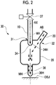
Fig. 2 is a cross-sectional diagram of an injection unit according to the first embodiment. -
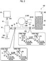
Fig. 3 is a diagram for explaining an operation of the machining apparatus of the first embodiment. -
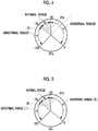
Fig. 4 is a diagram for explaining an operation of a detection unit according to the first embodiment. -
Fig. 5 is a diagram for explaining an operation of a modification example of the detection unit of the first embodiment. -
Fig. 6 is an overall schematic diagram of a machining apparatus according to a second embodiment. -
Fig. 7 is a cross-sectional diagram of an injection unit according to the second embodiment. -
Fig. 8 is a flowchart of a machining method in each embodiment. - Hereinafter, various embodiments according to the present invention will be described with reference to the drawings.
- Hereinafter, a machining apparatus according to a first embodiment of the present invention will be described with reference to
Figs. 1 to 5 . - A
machining apparatus 100 of the present embodiment is a cutting apparatus using an abrasive water jet and cuts an object to be machined OBJ. - As illustrated in
Fig. 1 , themachining apparatus 100 includes a high-pressure water pipe 10, anabrasive grain pipe 20, aninjection unit 30, adetection unit 40, a high-pressure pump 50, and ahopper 60. Themachining apparatus 100 injects high-pressure mixed water MH containing abrasive grains AB to the object to be machined OBJ. - The high-
pressure water pipe 10 connects the high-pressure pump 50 and theinjection unit 30 to each other. - The high-
pressure pump 50 pressurizes water into high-pressure water WH and supplies the high-pressure water WH to theinjection unit 30 via the high-pressure water pipe 10. - Therefore, the high-pressure water WH can be supplied to the
injection unit 30 through the high-pressure water pipe 10. - The
abrasive grain pipe 20 connects a lower portion of thehopper 60 and theinjection unit 30 to each other. - An inside of the
hopper 60 is filled with the abrasive grains AB. The abrasive grains AB are supplied into thehopper 60 from an opening on an upper portion of thehopper 60 by another device or an operator. - In the abrasive grains AB in the
hopper 60, the abrasive grains AB located in a lower portion of thehopper 60 are pressurized by the gravity and extruded to theabrasive grain pipe 20 connected to the lower portion of thehopper 60. Thereby, thehopper 60 supplies the extruded abrasive grains AB to theinjection unit 30 via theabrasive grain pipe 20. - Therefore, the abrasive grains AB can be supplied to the
injection unit 30 through theabrasive grain pipe 20. - The
abrasive grain pipe 20 has amain pipe 20A and abranch pipe 20B. Themain pipe 20A extends from thehopper 60 toward theinjection unit 30. Thebranch pipe 20B branches off from themain pipe 20A in a middle of themain pipe 20A. - The
injection unit 30 mixes the supplied high-pressure water WH with the abrasive grains AB inside theinjection unit 30 to inject the high-pressure mixed water MH. - The
detection unit 40 measures a pressure PM inside theabrasive grain pipe 20 at a measurement location, detects that the pressure PM is lower than a lower threshold value, and further detects that the pressure PM is higher than the upper threshold value. - As illustrated in
Fig. 2 , theinjection unit 30 includes a high-pressurewater introduction portion 31, an abrasivegrain introduction portion 32, anorifice 34, a chamber 35 (mixing portion), and anozzle 36. - The
chamber 35 is a pressure vessel having a substantially hollow cylindrical shape extending in an axis AX direction with an axis AX as a cylindrical axis. Thechamber 35 is sealed except for various openings, and a pressure inside thechamber 35 can be a low pressure by closing the various openings. - In the
chamber 35, the high-pressure water WH introduced from the high-pressurewater introduction portion 31 and the abrasive grains AB introduced from the abrasivegrain introduction portion 32 are mixed with each other in a space between theorifice 34 and a lower surface of thechamber 35, and thus, become the high-pressure mixed water MH. - The high-pressure
water introduction portion 31 includes an opening which is provided on an upper surface of thechamber 35 and has the axis AX as a center. By connecting the high-pressure water pipe 10 to the high-pressurewater introduction portion 31, the high-pressure water WH is introduced from the high-pressurewater introduction portion 31 into theinjection unit 30. - The introduced high-pressure water WH is supplied to the
orifice 34 via the high-pressurewater introduction portion 31. - The abrasive
grain introduction portion 32 is provided in an opening on an upper portion of an outer periphery of thechamber 35. By connecting theabrasive grain pipe 20 to the abrasivegrain introduction portion 32, the abrasive grains AB are introduced from the abrasivegrain introduction portion 32 into theinjection unit 30. - The
orifice 34 has a throughhole 34H which extends from the high-pressurewater introduction portion 31 toward thenozzle 36 about the axis AX. A base end of theorifice 34 is connected to the high-pressurewater introduction portion 31. A tip of theorifice 34 is directed toward thenozzle 36. The throughhole 34H on a tip side of theorifice 34 faces thenozzle 36. The tip of theorifice 34 and thenozzle 36 are separated from each other across a space. - The through
hole 34H is a hole which opens from a base end side of theorifice 34 toward a tip side of theorifice 34. - As an example, the through
hole 34H may be a hole of an inner diameter decreases from the base end side of theorifice 34 toward the tip side of theorifice 34. - As another example, the through
hole 34H may be a small-diameter hole which opens to have a simply fixed hole diameter from the base end side of theorifice 34 toward the tip side of theorifice 34. - In any case, the
orifice 34 is made of a hard material such as diamond or ruby to suppress wear. As a result, theorifice 34 injects the high-pressure water introduced into the high-pressurewater introduction portion 31 toward thenozzle 36 from the tip side of theorifice 34. - The
nozzle 36 protrudes downward from an opening on the lower surface of thechamber 35. - The
nozzle 36 extends toward a tip which protrudes from a base end on a lower surface side of thechamber 35. An upper end of thenozzle 36 is connected to the opening on the lower surface of thechamber 35. Thenozzle 36 has anozzle hole 36H which penetrates from an upper end toward a lower end about the axis AX. - The
nozzle 36 has a tubular shape in which thenozzle hole 36H generally has a constant diameter from a base end to a tip without changing an inner diameter of thenozzle hole 36H. Thenozzle hole 36H has a certain length, and thus, has a function of rectifying the high-pressure mixed water MH to make the high-pressure mixed water to a narrowed flow which is not diffused. Thereby, thenozzle 36 injects the narrowed high-pressure mixed water MH toward the object to be machined OBJ from the tip of thenozzle 36. - Here, the high-pressure water WH is injected from the
orifice 34 at a high pressure. Therefore, the high-pressure mixed water MH is also injected from thenozzle 36 at a high pressure without a change in pressure. - Returning to
Fig. 1 , thedetection unit 40 includes ameasurement unit 41 and adetermination unit 42. - The
measurement unit 41 measures the pressure PM inside theabrasive grain pipe 20. In the present embodiment, themeasurement unit 41 is connected to a branch end of thebranch pipe 20B. For this reason, themeasurement unit 41 measures the pressure PM inside thebranch pipe 20B at the branch end of thebranch pipe 20B which is a measurement location. - The
measurement unit 41 provides the measured pressure PM to thedetermination unit 42. - The
determination unit 42 detects that the obtained pressure PM is small. Specifically, thedetermination unit 42 compares the obtained pressure PM with a preset lower threshold value PL. Then, in a case where the pressure PM is lower than the lower threshold value PL, thedetermination unit 42 detects the intention. - The
determination unit 42 detects that the obtained pressure PM is large. Specifically, thedetermination unit 42 further compares the pressure PM with a preset upper threshold value PH. Then, in a case where the obtained pressure PM is higher than the upper threshold value PH, thedetermination unit 42 detects the intention. - As the lower threshold value PL and the upper threshold value PH, a lower limit and an upper limit of the pressure PM when a desired machining ability is obtained are set, respectively. The lower limit value and the upper limit value of the pressure PM at which a desired machining ability can be obtained are determined in advance by experience, results, experiments, or the like.
- For example, the
measurement unit 41 is a Bourdon tube pressure gauge, and as illustrated inFig. 3 , sets a pressure at the time of the atmospheric pressure to 0 kPa and measures a pressure difference from the atmospheric pressure as the pressure. In the present embodiment, in thedetermination unit 42, -50 kPa is set as the upper threshold value PH, and -70 kPa is set as the lower threshold value PL. - In a case where the
detection unit 40 detects that the obtained pressure PM is lower than the lower threshold value PL or in a case where thedetection unit 40 detects that the obtained pressure PM is higher than the upper threshold value PH, thedetection unit 40 may immediately output a command to stop a supply of the high-pressure water to the high-pressure pump 50. - Moreover, in a case where the
detection unit 40 detects that the pressure PM is lower than the lower threshold value PL or in a case where thedetection unit 40 detects that the obtained pressure PM is higher than the upper threshold value PH, thedetection unit 40 may output a command to a high-pressure valve 37 which is provided immediately before the high-pressurewater introduction portion 31 in the middle of the high-pressure water pipe 10 and may control the high-pressure valve so that the high-pressure valve is blocked immediately after the detection. - The
machining apparatus 100 supplies the high-pressure water WH from the high-pressure water pipe 10 and the abrasive grains AB from theabrasive grain pipe 20 to theinjection unit 30, respectively. The high-pressure water WH and the abrasive grains AB introduced into theinjection unit 30 are mixed with each other inside thechamber 35 and become the high-pressure mixed water MH. Themachining apparatus 100 injects the mixed high-pressure mixed water MH toward the object to be machined OBJ from the tip of thenozzle 36. - At this time, in a case where the
detection unit 40 measures the pressure PM inside theabrasive grain pipe 20 and detects that the pressure PM is lower than the lower threshold value PL, thedetection unit 40 detects the intention. Meanwhile, in a case where the pressure PM is higher than the upper threshold value PH, thedetection unit 40 detects the intention. - In the present embodiment, the
detection unit 40 measures the pressure PM inside theabrasive grain pipe 20. - In this case, the
hopper 60 supplies the extruded abrasive grains AB to theinjection unit 30 via theabrasive grain pipe 20. Therefore, The pressure in theabrasive grain pipe 20 at least at the upstream end of theabrasive grain pipe 20 is higher than the downstream end connected to theinjection part 30 due to pressure loss in the pipe, but is lower than the atmospheric pressure. - Meanwhile, the high-pressure water WH introduced from the high-pressure
water introduction portion 31 is injected from theorifice 34. Accordingly, a negative pressure is formed immediately below theorifice 34 by a Venturi effect, and the abrasive grains AB introduced from the abrasivegrain introduction portion 32 are sucked. For this reason, a pressure inside theabrasive grain pipe 20 in at least a downstream end of theabrasive grain pipe 20 is at least lower than the atmospheric pressure. - For example, if the abrasive grain AB is clogged in the
abrasive grain pipe 20 on the upstream side of the connecting portion of thebranch pipe 20B,the pressure PM is lower than that when the abrasive grains AB are not clogged. The same applies to clogging in thehopper 60. - Therefore, when the
detection unit 40 detects that the measured pressure is lower than the lower threshold value PL, it is possible to detect that the abrasive grains AB are clogged on the upstream side (including the hopper 60) of thebranch pipe 20B. - For example, if the abrasive grains AB are clogged in the
abrasive grain pipe 20 on a downstream side of thebranch pipe 20B and theabrasive grain pipe 20 is blocked on the downstream side of thebranch pipe 20B, the pressure PM is higher than that when the abrasive grains AB are not clogged. The same applies to clogging in thenozzle 36, clogging in the abrasivegrain introduction portion 32, or the like. - Therefore, if the
detection unit 40 detects that the measured pressure is higher than the upper threshold value PH, it is possible to detect that the abrasive grains AB are clogged on the downstream side (including the nozzle 36) of thebranch pipe 20B. - Therefore, the
machining apparatus 100 can detect the clogging of the abrasive grains AB. - The
machining apparatus 100 using the abrasive water jet as in the present embodiment can vigorously inject the high-pressure water mixed with abrasive grains AB from a nozzle to perform trimming (trimming machining). Further, in general, themachining apparatus 100 using the abrasive water jet as in the present embodiment is usually used for cutting a hard-to-cut material, and, for example, can perform trimming (trimming machining) of a wing skin. - The abrasive grains AB are mixed in order to increase power of the abrasive water jet, and an abrasive such as SiC or Al2O3 having a particle size of about several hundred of µm is used in many cases.
- In order to transport the abrasive grains AB, vacuum transport performed by an aspirator using the Venturi effect of a water jet is often used as in the
machining apparatus 100 of the present embodiment. The reason for using the vacuum transport performed by an aspirator is that there is no need to use a new power for transporting the abrasive grains, and the apparatus can be simplified. - However, if the abrasive grains AB are clogged in the
nozzle 36 or the abrasive grains AB are instantaneously clogged in theabrasive grain pipe 20, the pressure of the jet may temporarily decrease. In this state, not only does a "sharpness" of the trim become poor and cutting quality sharply decreases, but also the cutting is impossible if a pressure decrease time of the jet is long. - The abrasive grains AB have a sharp shape in order to improve cutting performance and quality, and because of this shape, fluidity is poor and the clogging is likely to occur essentially.
- As illustrated in
Fig. 3 , it is assumed that the abrasive grains AB are clogged and themain pipe 20A is blocked at a position XL on the downstream side of thebranch pipe 20B. In this case, the pressure detected by thedetection unit 40 is higher than that in a normal state,since the negative pressure of the venturi effect sucked by theinjection unit 30 decreases. - Therefore, when the
detection unit 40 detects that the pressure PM is higher than the upper threshold value PH, thedetection unit 40 can detect the blockage on the downstream side of the detection unit 4. - However, in actual, as illustrated in
Fig. 3 , the blockage by the abrasive grains AB may occur not only on a downstream side than thebranch pipe 20B, but also at a position XH on an upstream side of thebranch pipe 20B. - It is assumed that the
main pipe 20A is blocked by the abrasive grains AB at the position XH. In this case, due to the negative pressure of the Venturi effect, the pressure detected by thedetection unit 40 is lower than that in the normal state. That is, the change is opposite to a case where the abrasive grains AB is clogged on the downstream side of thebranch pipe 20B. - Therefore, the
detection unit 40 not only detects that the pressure PM is higher than the upper threshold value PH, but also detects that the pressure PM is lower than the lower threshold value PL. - That is, as illustrated in
Fig. 4 , thedetection unit 40 determines that the pressure PM is not in a range (normal range) in which the pressure PM is the lower threshold value PL or more and the upper threshold value PH or less, and thedetection unit 40 determines that the pressure PM is in a range lower than the lower threshold value PL or in a range (abnormal range) more than the upper threshold value PH. - In general, in the abrasive water jet, the pressure in the
abrasive grain pipe 20 fluctuates according to a pressure fluctuation of a high-pressure pump, a water temperature which determines the negative pressure of the Venturi effect, and flow conditions of the abrasive grains AB. Therefore, it is necessary to determine a range which is not abnormal. - As in the present embodiment, for example, when the upper threshold value PH is set to -50 kPa and the lower threshold value PL is set to -70 kPa, it is possible to cope with the fluctuation. This value may vary depending on various conditions.
- If there is a blockage on an upstream side of a pressure measurement location (
branch pipe 20B) by thedetection unit 40, the flows of the abrasive grains AB stop or an amount of the flow decreases. Accordingly, a sharpness of the jet injected from themachining apparatus 100 deteriorates, and a cut surface of the object to be machined OBJ is rough or the object to be machined OBJ cannot be cut. - Meanwhile, if there is a blockage on a downstream side of the pressure measurement location (
branch pipe 20B) by thedetection unit 40, at least one of the blockage of theabrasive grain pipe 20 and the blockage of theinjection unit 30 occurs. When theabrasive grain pipe 20 is blocked, the flows of the abrasive grains AB are stopped as described above. When theinjection unit 30 is blocked, the jet injected from themachining apparatus 100 stops. - When the flows of the abrasive grains AB are stopped or the jet injected from the
machining apparatus 100 is stopped, the sharpness of the jet becomes deteriorates as described above, and the cut surface of the workpiece is rough or the workpiece cannot be cut. - In this situation, the trimming cannot be restarted immediately after the blockage is eliminated, and the rough cut surface needs to be repaired by any method.
- Meanwhile, the
machining apparatus 100 of the present embodiment can detect the clogging of the abrasive grains AB. Further, it is possible to detect whether the clogged location of the abrasive grains AB is the upstream side or the downstream side of thebranch pipe 20B which is the pressure detection location of thedetection unit 40. For this reason, it is possible to cope before the cut surface is rough or cannot be cut, and thus, an impact is extremely large in terms of cost and a delivery date. - In the present embodiment, the
detection unit 40 detects that the pressure PM is in the range lower than the lower threshold value PL or in the range (abnormal range) higher than the upper threshold value PH. As a modification example, as illustrated inFig. 5 , thedetection unit 40 may separately detect that the pressure PM is in the range (abnormal range (I)) lower than the lower threshold value PL and the pressure PM is in the range higher than the upper threshold value PH (abnormal range (II).) - Furthermore, when the pressure PM is in the abnormal range (I), the
detection unit 40 may specify that there is an abnormality (blockage) on the upstream side of the pressure measurement location by thedetection unit 40, and when the pressure PM is in the abnormal range (II), thedetection unit 40 may specify that there is an abnormality (blockage) on the downstream side of the pressure measurement location by thedetection unit 40. - Hereinafter, a machining apparatus according to a second embodiment of the present invention will be described with reference to
Fig. 6 . - A
machining apparatus 200 of the present embodiment is basically the same as that of the first embodiment, but is different from that of the first embodiment in that a vacuum pump is provided. Moreover, constitutions of injection units are different from each other. - The
machining apparatus 200 includes the high-pressure water pipe 10, theabrasive grain pipe 20, aninjection unit 230, thedetection unit 40, the high-pressure pump 50, and thehopper 60. As illustrated inFig. 6 , themachining apparatus 200 further includes avacuum pump 80. - As illustrated in
Fig. 7 , theinjection unit 230 mixes the supplied high-pressure water WH with the abrasive grains AB inside theinjection unit 30 to inject the high-pressure mixed water MH. - The
injection unit 230 include the high-pressurewater introduction portion 31, the abrasivegrain introduction portion 32, anexhaust portion 33, theorifice 34, a chamber 235 (mixing portion), thenozzle 36, and apartition pipe 70. - The
partition pipe 70 is provided inside thechamber 235. Thepartition pipe 70 separates a first space SP1 extending in one direction from the high-pressurewater introduction portion 31 to thenozzle 36 and the second space SP2 around the first space SP1. - The
partition pipe 70 has anopening 70H on an introduction straight line Li extending in introduction directions of the abrasive grains AB from the abrasivegrain introduction portion 32. - The
exhaust portion 33 is provided at a position facing the abrasivegrain introduction portion 32 across the first space SP1. This position is best. However, the second space SP2 may be provided anywhere as long as it is a place where the second space SP2 can be exhausted and does not affect the flow of abrasive grains passing through theopening 70H. Avacuum pump 80 is connected to theexhaust portion 33. Thevacuum pump 80 exhausts gas in the second space SP2 from theexhaust portion 33. - A pressure inside the
chamber 235 is reduced by thevacuum pump 80. Therefore, most of the abrasive grains AB introduced from the abrasivegrain introduction portion 32 are accelerated in the direction of the introduction straight line Li so as to be sucked into thechamber 235. Moreover, most of the accelerated abrasive grains AB rush into theopening 70H due to inertial motion, are mixed with the high-pressure water WH to be the high-pressure mixed water MH, and are injected from thenozzle 36. - In general, the negative pressure formed by the Venturi effect has many small fluctuations. Accordingly, when the abrasive grains AB are transported into the injection unit using the Venturi effect as in the first embodiment, a transport amount of the abrasive grains AB may be unstable. When the transport amount of the abrasive grains AB is unstable, it is difficult to keep a transport flow rate of the abrasive grains AB into the injection unit high.
- Further, the negative pressure due to the Venturi effect of the high-pressure jet is small. In this case, when the
vacuum pump 80 is separately provided and the abrasive grains AB are transported by decompressed air, it is possible to increase the flow rate. - Therefore, in the present embodiment, the air inside the second space SP2 is exhausted using an independent dedicated system for introducing the abrasive grains, and in the
machining apparatus 200, theseparate vacuum pump 80 is provided to transport the abrasive grains AB by decompressed air. - For this reason, it is possible to keep the flow rate of the abrasive grains AB into the
injection unit 230 large. - In addition, effects of suppressing the negative pressure fluctuation of the high-pressure jet can be expected.
- Therefore, it is possible to suppress the clogging of the abrasive grains AB.
- In addition, in the present embodiment, in the
machining apparatus 200, thepartition pipe 70 is provided inside thechamber 235. Further, in themachining apparatus 200, theexhaust portion 33 is provided at the position facing the abrasivegrain introduction portion 32 across the first space SP1. Accordingly, solid (abrasive grain) - gas (air) separation can be performed inside theinjection unit 230. - If the air inside the
chamber 235 is exhausted at a pressure lower than the pressure formed by the Venturi effect without providing thepartition pipe 70, the flows of the abrasive grains AB from the abrasivegrain introduction portion 32 to theopening 70H on the introduction straight line Li are obstructed. - Meanwhile, in the present embodiment, since the
partition pipe 70 is provided, the flows of the abrasive grains AB on the introduction straight line Li are not easily obstructed. As a result, the abrasive grains AB are introduced from the abrasivegrain introduction portion 32 into the first space SP1 through theopening 70H. - Therefore, it is possible to further suppress the clogging of the abrasive grains AB.
- The machining method in each of the embodiments will be described with reference to
Fig. 8 . - Hereinafter, a case where the
machining apparatus 100 is used will be described. However, the same applies to a case where themachining apparatus 200 is used. - First, the
machining apparatus 100 measures the pressure inside the abrasive grain pipe 20 (ST10: a step of measuring the pressure). - Subsequent to ST10, the
machining apparatus 100 compares the obtained pressure PM with the preset lower threshold value PL (ST20: a step of comparing with the lower threshold value). - As a result of the comparison, in a case where the
machining apparatus 100 determines that the obtained pressure PM is lower than the preset lower threshold value PL (ST20: YES), the process proceeds to ST40. - As a result of the comparison, when the
machining apparatus 100 determines that the obtained pressure PM is not lower than the preset lower threshold value PL (ST20: NO), the process proceeds to ST30. - In ST30, the
machining apparatus 100 compares the pressure PM with the preset upper threshold value PH (ST30: a step of comparing with the upper threshold value). - As a result of the comparison, in a case where the
machining apparatus 100 determines that the obtained pressure PM is not higher than the preset upper threshold value PH (ST30: NO), the process returns to ST10, and the pressure inside theabrasive grain pipe 20 is measured again. - As a result of the comparison, in a case where the
machining apparatus 100 determines that the obtained pressure PM is higher than the preset upper threshold value PH (ST30: YES), the process proceeds to ST40. - In ST40, the
machining apparatus 100 detects that pressure PM is out of the range (the pressure PM is lower than the lower threshold value PL or higher than the upper threshold value PH). - Subsequent to ST40, when detecting that the obtained pressure PM is lower than the lower threshold value PL or detecting that the pressure PM is higher than the upper threshold value PH, the
detection unit 40 immediately supplies high-pressure water to the high-pressure pump 50. A command to stop is output (ST50: output step). Further, in ST50, in a case where thedetection unit 40 detects that the pressure PM is lower than the lower threshold value PL, or in a case where thedetection unit 40 detects that the pressure PM is higher than the upper threshold value PH, thedetection unit 40 may output a command to the high-pressure valve 37 which is provided immediately before the high-pressurewater introduction portion 31 in the middle of the high-pressure water pipe 10 as illustrated inFig. 2 . The high-pressure valve 37 receiving the command stops the injection of the high-pressure water WH, and thus, themachining apparatus 100 stops the injection of the high-pressure mixed water MH. - Each step of the present machining method is performed by the machining apparatus. However, as a modification example, at least one of steps ST10 to ST50 may be performed by an operator.
- Moreover, in steps ST20 and ST30 of the machining method, the machining apparatus compares the obtained pressure PM with the lower threshold value PL and also compares the obtained pressure PM with the upper threshold value PH. However, as a modification example, it is not necessary to compare the obtained pressure PM with the upper threshold value PH only by comparing the obtained pressure PM with the preset lower threshold value PL. In this case, in ST40, the machining apparatus detects only that the pressure PM is lower than the lower threshold value, and does not detect that the pressure PM is higher than the upper threshold value PH.
- Hereinbefore, some embodiments of the present invention are described. However, the embodiments are presented by way of example only, and are not intended to limit a scope of the invention. The embodiments can be implemented in other various forms, and various omissions, replacements, and modifications can be made within a scope which does not depart from the gist of the invention. The embodiments and modifications thereof are included in the scope and gist of the invention, and are also included in the invention described in the claims and equivalents thereof.
- For example, in each of the embodiments, the machining apparatus and the machining method perform cutting of the object to be machined OBJ, but may perform machining of the object to be machined OBJ even without cutting the object to be machined OBJ.
- According to an aspect of the present invention, it is possible to detect clogging of abrasive grains. Reference Signs List
-
- 10:
- high-pressure water pipe
- 20:
- abrasive grain pipe
- 20A:
- main pipe
- 20B:
- branch pipe
- 30:
- injection unit
- 31:
- high-pressure water introduction portion
- 32:
- abrasive grain introduction portion
- 33:
- exhaust portion
- 34:
- orifice
- 34H:
- through hole
- 35:
- chamber
- 36:
- nozzle
- 36H:
- nozzle hole
- 37:
- high-pressure valve
- 40:
- detection unit
- 41:
- measurement unit
- 42:
- determination unit
- 50:
- high-pressure pump
- 60:
- hopper
- 70:
- partition pipe
- 70H:
- opening
- 80:
- vacuum pump
- 100:
- machining apparatus
- 200:
- machining apparatus
- 230:
- injection unit
- 235:
- chamber
- AB:
- abrasive grain
- AX:
- axis
- Li:
- introduction straight line
- MH:
- high-pressure mixed water
- OBJ:
- object to be machined
- PH:
- upper threshold value
- PL:
- lower threshold value
- PM:
- pressure
- SP1:
- first space
- SP2:
- second space
- WH:
- high-pressure water
Claims (6)
- A machining apparatus comprising:
a high-pressure water pipe through which high-pressure water is supplied;
an abrasive grain pipe through which abrasive grains are supplied;
an injection unit which includes a high-pressure water introduction portion into which the high-pressure water is introduced, an abrasive grain introduction portion into which the abrasive grains are introduced, a mixing portion in which the high-pressure water and the abrasive grains are mixed with each other, and a nozzle which injects the high-pressure water having the mixed abrasive grains to an object to be machined; and
a detection unit which measures a pressure inside the abrasive grain pipe and detects that the pressure is lower than a lower threshold value. - The machining apparatus according to claim 1, wherein the detection unit further detects that the pressure is higher than an upper threshold value.
- The machining apparatus according to claim 1 or 2, wherein the detection unit specifies that an abnormality is present on an upstream side of a pressure measurement location by the detection unit in a case where the pressure is lower than the lower threshold value.
- The machining apparatus according to any one of claims 1 to 3, further comprising:
a partition pipe which separates a first space extending in one direction from the high-pressure water introduction portion to the nozzle and a second space around the first space from each other, inside the mixing portion and includes an opening on an introduction straight line extending in an introduction direction of the abrasive grains from the abrasive grain introduction portion; and
an exhaust portion which is provided at a position facing the abrasive grain introduction portion across the first space and exhausts air inside the second space. - A machining apparatus comprising:
a high-pressure water pipe through which high-pressure water is supplied;
an abrasive grain pipe through which abrasive grains are supplied;
an injection unit which includes a high-pressure water introduction portion into which the high-pressure water is introduced, an abrasive grain introduction portion into which the abrasive grains are introduced, a mixing portion in which the high-pressure water and the abrasive grains are mixed with each other, and a nozzle which injects the high-pressure water having the mixed abrasive grains to an object to be machined; and
a partition pipe which separates a first space extending in one direction from the high-pressure water introduction portion to the nozzle and a second space around the first space from each other, inside the mixing portion and includes an opening on an introduction straight line extending in an introduction direction of the abrasive grains from the abrasive grain introduction portion; and
an exhaust portion which is provided at a position facing the abrasive grain introduction portion across the first space and exhausts air inside the second space. - A machining method comprising:
a step of measuring a pressure inside an abrasive grain pipe of a machining apparatus including a high-pressure water pipe through which high-pressure water is supplied, an abrasive grain pipe through which abrasive grains are supplied, and a nozzle which is connected to the high-pressure water pipe and the abrasive grain pipe and injects the high-pressure water mixed with the abrasive grains to an object to be machined; and
a step of detecting that the pressure is lower than a lower threshold value.
Applications Claiming Priority (2)
| Application Number | Priority Date | Filing Date | Title |
|---|---|---|---|
| JP2018014975A JP6959157B2 (en) | 2018-01-31 | 2018-01-31 | Processing equipment and processing method |
| PCT/JP2019/000331 WO2019150893A1 (en) | 2018-01-31 | 2019-01-09 | Machining apparatus and machining method |
Publications (1)
| Publication Number | Publication Date |
|---|---|
| EP3747601A1 true EP3747601A1 (en) | 2020-12-09 |
Family
ID=67479971
Family Applications (1)
| Application Number | Title | Priority Date | Filing Date |
|---|---|---|---|
| EP19746984.4A Withdrawn EP3747601A1 (en) | 2018-01-31 | 2019-01-09 | Machining apparatus and machining method |
Country Status (4)
| Country | Link |
|---|---|
| US (1) | US20200346321A1 (en) |
| EP (1) | EP3747601A1 (en) |
| JP (1) | JP6959157B2 (en) |
| WO (1) | WO2019150893A1 (en) |
Families Citing this family (3)
| Publication number | Priority date | Publication date | Assignee | Title |
|---|---|---|---|---|
| CN112454178A (en) * | 2020-11-16 | 2021-03-09 | 上海狮迈科技有限公司 | Nozzle fault monitoring system and monitoring method |
| CN117161955A (en) * | 2023-11-02 | 2023-12-05 | 乍浦科技(江苏)有限责任公司 | Bolt processing rust cleaning device |
| CN118789468A (en) * | 2024-07-30 | 2024-10-18 | 山东大学 | A high-pressure water jet multi-degree-of-freedom cutting actuator and method |
Family Cites Families (11)
| Publication number | Priority date | Publication date | Assignee | Title |
|---|---|---|---|---|
| US4478368A (en) * | 1982-06-11 | 1984-10-23 | Fluidyne Corporation | High velocity particulate containing fluid jet apparatus and process |
| FI904296A7 (en) * | 1988-03-02 | 1990-08-31 | Cleaning Tech Limited | Abrasive cleaning or cutting method |
| JPH0219466U (en) | 1988-07-26 | 1990-02-08 | ||
| JPH0259268A (en) * | 1988-08-25 | 1990-02-28 | Kenzo Hoshino | Abrasive jet method |
| JPH0780773A (en) * | 1993-09-16 | 1995-03-28 | Nippon Steel Corp | Descaling slurry concentration monitor |
| JPH10156723A (en) * | 1996-12-02 | 1998-06-16 | Ebara Corp | Machining device using high pressure water jet |
| JP2008068368A (en) * | 2006-09-14 | 2008-03-27 | Hitachi Plant Technologies Ltd | Blasting equipment |
| JP5205481B2 (en) * | 2011-02-02 | 2013-06-05 | 株式会社スギノマシン | Abrasive water jet machine |
| GB201204253D0 (en) * | 2012-03-11 | 2012-04-25 | Miller Donald S | Abrasive suspension feed system |
| JP2013215854A (en) * | 2012-04-10 | 2013-10-24 | Sugino Machine Ltd | Abrasive water jet nozzle, and abrasive water jet machine |
| JP6694349B2 (en) | 2016-07-29 | 2020-05-13 | グローブライド株式会社 | Spinning reel for fishing |
-
2018
- 2018-01-31 JP JP2018014975A patent/JP6959157B2/en active Active
-
2019
- 2019-01-09 WO PCT/JP2019/000331 patent/WO2019150893A1/en not_active Ceased
- 2019-01-09 EP EP19746984.4A patent/EP3747601A1/en not_active Withdrawn
- 2019-01-09 US US16/754,558 patent/US20200346321A1/en not_active Abandoned
Also Published As
| Publication number | Publication date |
|---|---|
| WO2019150893A1 (en) | 2019-08-08 |
| JP2019130614A (en) | 2019-08-08 |
| US20200346321A1 (en) | 2020-11-05 |
| JP6959157B2 (en) | 2021-11-02 |
Similar Documents
| Publication | Publication Date | Title |
|---|---|---|
| EP2489470B1 (en) | Method for thin kerf cutting and in-situ recycling | |
| US20200346321A1 (en) | Machining apparatus and machining method | |
| US8342912B2 (en) | Abrasive water jet processing machine | |
| US9844890B2 (en) | Fluid distribution components of high-pressure fluid jet systems | |
| EP2321093B1 (en) | Vented cutting head body for abrasive jet system | |
| US8308525B2 (en) | Processes and apparatuses for enhanced cutting using blends of abrasive materials | |
| JP2903249B2 (en) | Cutting head for water jet type cutting equipment | |
| EP1423235B1 (en) | Apparatus for generating a high-pressure fluid jet | |
| US7584546B2 (en) | Alignment control for a water-jet cutting system | |
| EP4186639B1 (en) | Air flow management systems to facilitate the delivery of abrasives to an abrasive fluid jet cutting head | |
| US20030037654A1 (en) | Apparatus for generating a high-pressure fluid jet | |
| BRPI0809278B1 (en) | PROCESS AND DEVICE FOR THE PRODUCTION OF MOLDS WITH A POLYURETHANE LAYER | |
| JP2013215854A (en) | Abrasive water jet nozzle, and abrasive water jet machine | |
| US7207868B2 (en) | Cutting apparatus | |
| US20130125600A1 (en) | Method for shot-peening and a shot-peening machine | |
| US20010030245A1 (en) | Pressurized abrasive feed and metering system for waterjet cutting systems | |
| US9653876B2 (en) | Gas laser apparatus for determining composition ratio of laser gas | |
| EP2853349A1 (en) | Abrasive water jet cutting nozzle | |
| JP6511009B2 (en) | Nozzle device | |
| EP3632618B1 (en) | Abrasive water-jet cutting machine and method, and composition comprising abrasive material | |
| CN210499485U (en) | Special cooling gun for numerical control machine tool | |
| JP2006263547A (en) | Water jet nozzle device | |
| CN86105044A (en) | Streamer Stabilizer and Stabilization Method for Front-edge Nozzle Hole | |
| JP2004195623A (en) | Direct pressure type air blast device and operation control method of its device |
Legal Events
| Date | Code | Title | Description |
|---|---|---|---|
| STAA | Information on the status of an ep patent application or granted ep patent |
Free format text: STATUS: THE INTERNATIONAL PUBLICATION HAS BEEN MADE |
|
| PUAI | Public reference made under article 153(3) epc to a published international application that has entered the european phase |
Free format text: ORIGINAL CODE: 0009012 |
|
| STAA | Information on the status of an ep patent application or granted ep patent |
Free format text: STATUS: REQUEST FOR EXAMINATION WAS MADE |
|
| 17P | Request for examination filed |
Effective date: 20200417 |
|
| AK | Designated contracting states |
Kind code of ref document: A1 Designated state(s): AL AT BE BG CH CY CZ DE DK EE ES FI FR GB GR HR HU IE IS IT LI LT LU LV MC MK MT NL NO PL PT RO RS SE SI SK SM TR |
|
| AX | Request for extension of the european patent |
Extension state: BA ME |
|
| DAV | Request for validation of the european patent (deleted) | ||
| DAX | Request for extension of the european patent (deleted) | ||
| STAA | Information on the status of an ep patent application or granted ep patent |
Free format text: STATUS: THE APPLICATION HAS BEEN WITHDRAWN |
|
| 18W | Application withdrawn |
Effective date: 20210709 |