EP3747548A1 - Electrode assembly manufacturing apparatus equipped with air purifying function - Google Patents
Electrode assembly manufacturing apparatus equipped with air purifying function Download PDFInfo
- Publication number
- EP3747548A1 EP3747548A1 EP19838168.3A EP19838168A EP3747548A1 EP 3747548 A1 EP3747548 A1 EP 3747548A1 EP 19838168 A EP19838168 A EP 19838168A EP 3747548 A1 EP3747548 A1 EP 3747548A1
- Authority
- EP
- European Patent Office
- Prior art keywords
- electrode assembly
- manufacturing
- air
- air blower
- electrode
- Prior art date
- Legal status (The legal status is an assumption and is not a legal conclusion. Google has not performed a legal analysis and makes no representation as to the accuracy of the status listed.)
- Granted
Links
Images



Classifications
-
- H—ELECTRICITY
- H01—ELECTRIC ELEMENTS
- H01M—PROCESSES OR MEANS, e.g. BATTERIES, FOR THE DIRECT CONVERSION OF CHEMICAL ENERGY INTO ELECTRICAL ENERGY
- H01M10/00—Secondary cells; Manufacture thereof
- H01M10/04—Construction or manufacture in general
- H01M10/0404—Machines for assembling batteries
- H01M10/0409—Machines for assembling batteries for cells with wound electrodes
-
- B—PERFORMING OPERATIONS; TRANSPORTING
- B65—CONVEYING; PACKING; STORING; HANDLING THIN OR FILAMENTARY MATERIAL
- B65H—HANDLING THIN OR FILAMENTARY MATERIAL, e.g. SHEETS, WEBS, CABLES
- B65H18/00—Winding webs
- B65H18/08—Web-winding mechanisms
- B65H18/10—Mechanisms in which power is applied to web-roll spindle
-
- B—PERFORMING OPERATIONS; TRANSPORTING
- B65—CONVEYING; PACKING; STORING; HANDLING THIN OR FILAMENTARY MATERIAL
- B65H—HANDLING THIN OR FILAMENTARY MATERIAL, e.g. SHEETS, WEBS, CABLES
- B65H2301/00—Handling processes for sheets or webs
- B65H2301/50—Auxiliary process performed during handling process
- B65H2301/51—Modifying a characteristic of handled material
- B65H2301/511—Processing surface of handled material upon transport or guiding thereof, e.g. cleaning
- B65H2301/5115—Cleaning
-
- B—PERFORMING OPERATIONS; TRANSPORTING
- B65—CONVEYING; PACKING; STORING; HANDLING THIN OR FILAMENTARY MATERIAL
- B65H—HANDLING THIN OR FILAMENTARY MATERIAL, e.g. SHEETS, WEBS, CABLES
- B65H2406/00—Means using fluid
- B65H2406/10—Means using fluid made only for exhausting gaseous medium
-
- B—PERFORMING OPERATIONS; TRANSPORTING
- B65—CONVEYING; PACKING; STORING; HANDLING THIN OR FILAMENTARY MATERIAL
- B65H—HANDLING THIN OR FILAMENTARY MATERIAL, e.g. SHEETS, WEBS, CABLES
- B65H2801/00—Application field
- B65H2801/72—Fuel cell manufacture
-
- Y—GENERAL TAGGING OF NEW TECHNOLOGICAL DEVELOPMENTS; GENERAL TAGGING OF CROSS-SECTIONAL TECHNOLOGIES SPANNING OVER SEVERAL SECTIONS OF THE IPC; TECHNICAL SUBJECTS COVERED BY FORMER USPC CROSS-REFERENCE ART COLLECTIONS [XRACs] AND DIGESTS
- Y02—TECHNOLOGIES OR APPLICATIONS FOR MITIGATION OR ADAPTATION AGAINST CLIMATE CHANGE
- Y02E—REDUCTION OF GREENHOUSE GAS [GHG] EMISSIONS, RELATED TO ENERGY GENERATION, TRANSMISSION OR DISTRIBUTION
- Y02E60/00—Enabling technologies; Technologies with a potential or indirect contribution to GHG emissions mitigation
- Y02E60/10—Energy storage using batteries
-
- Y—GENERAL TAGGING OF NEW TECHNOLOGICAL DEVELOPMENTS; GENERAL TAGGING OF CROSS-SECTIONAL TECHNOLOGIES SPANNING OVER SEVERAL SECTIONS OF THE IPC; TECHNICAL SUBJECTS COVERED BY FORMER USPC CROSS-REFERENCE ART COLLECTIONS [XRACs] AND DIGESTS
- Y02—TECHNOLOGIES OR APPLICATIONS FOR MITIGATION OR ADAPTATION AGAINST CLIMATE CHANGE
- Y02P—CLIMATE CHANGE MITIGATION TECHNOLOGIES IN THE PRODUCTION OR PROCESSING OF GOODS
- Y02P70/00—Climate change mitigation technologies in the production process for final industrial or consumer products
- Y02P70/50—Manufacturing or production processes characterised by the final manufactured product
Definitions
- the present invention relates to a device for manufacturing an electrode assembly with an air purifying function.
- lithium rechargeable batteries such as a lithium ion battery or a lithium ion polymer battery having merits including high energy density, a good discharging voltage, and output stability.
- the rechargeable batteries are classified depending on the structures of an electrode assembly in which a positive electrode, a negative electrode, and a separation film provided between the positive electrode and the negative electrode are stacked.
- Typical ones include a jelly roll type (winding type) of electrode assembly in which a long sheet type of positive electrode and negative electrode are wound while a separation film is provided, and a stacking type of electrode assembly in which a plurality of positive electrodes and negative electrodes cut to a predetermined size of unit are sequentially stacked while a separation film is provided, and recently, in order to solve the drawbacks of the jelly roll type of electrode assembly and the stacking type of electrode assembly, a stacking/folding type of electrode assembly in which unit cells in which positive electrodes and negative electrodes with a predetermined size are stacked while a separation film is provided are sequentially wound while provided on a separation film as an electrode assembly with an advanced structure that is a mixture of the jelly roll type and the stacking type is being developed.
- the jelly roll type of electrode assembly has merits of easy manufacturing and high energy density per weight, so it is used as an energy source to various kinds of devices from laptop computers to cell vehicles.
- FIG. 1 shows a front view of a conventional device for manufacturing a jelly roll type of electrode assembly.
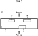
- FIG. 2 shows a top plan view of a device for manufacturing an electrode assembly of FIG. 1 .
- a positive electrode 11, a negative electrode 12, and a separation film 13 are wound by a winding portion 14, so they are made into a jelly roll shape.
- drawbacks such as a low voltage or a short circuit are generated, so the device 10 for manufacturing an electrode assembly is operated in a space for closing and sealing out external air.
- the device 10 for manufacturing an electrode assembly includes various installations such as an electrode transfer line 19, an electrode coalescing unit 15, an electrode incising unit 16, a power transmitter 17 (shown in FIG. 2 ), and a power supply 18 (shown in FIG. 2 ) in addition to the winding portion 14, and various foreign particles are generated by operation of the installations.
- various foreign particles are generated by operation of the installations.
- the foreign particles generated by the operation of the power transmitter 17 (shown in FIG. 2 ) and the power supply 18 (shown in FIG. 2 ) provided on a rear side of the device 10 for manufacturing an electrode assembly pass through a base hole 16 and are input to the winding portion 14.
- a method for installing an air blower at the front of the device 10 for manufacturing an electrode assembly, blowing air toward the rear side, and thus preventing foreign particles from being input to a front portion may be considered, but in this case, a moving line of a worker is disturbed, and provision of materials is difficult, so it is undesirable to install the air blower on the front side of the manufacturing device 10.
- An object of the present invention is to solve the problems of the prior art and technical problems from the past.
- the inventors of the present invention having performed in-depth research and experimentation, confirmed prevention of foreign particles from being input to a winding portion by installing an air blower in a top portion of a device for manufacturing an electrode assembly, and installing an outlet in a lateral bottom end portion of the device for manufacturing an electrode assembly, and completed the present invention.
- An exemplary embodiment of the present invention provides a device for manufacturing an electrode assembly for removing foreign particles through air circulation, including: a winding portion; an electrode transfer line; an air blower installed on a top portion of the device for manufacturing an electrode assembly and blowing air to a bottom portion of the device for manufacturing an electrode assembly; and an outlet for discharging air moved to the bottom portion by the air blower.
- the air blower may be installed in a transfer direction of the electrode transfer line.
- At least one air blower may be further installed to overlap the air blower in a direction crossing a direction in which the electrode transfer line is transferred on the upper portion corresponding to the winding portion.
- the outlet may be installed below the electrode transfer line.
- the outlet may be installed on a lateral bottom end portion of the device for manufacturing an electrode assembly.
- a device for manufacturing an electrode assembly includes a first device for manufacturing an electrode assembly and a second device for manufacturing an electrode assembly, and the first device for manufacturing an electrode assembly and the second device for manufacturing an electrode assembly are installed to face each other.
- a first air blower for blowing air to a winding portion of the first device for manufacturing an electrode assembly and a second air blower for blowing air to a winding portion of the second device for manufacturing an electrode assembly may be installed to face each other at a front.
- At least one air blower may be installed so that the electrode transfer line may overlap the first air blower and the second air blower in a direction crossing a transferring direction between the first air blower and the second air blower.
- An outlet may be installed on respective sides of a space between the first device for manufacturing an electrode assembly and the second device for manufacturing an electrode assembly.
- the phrase “on a plane” means viewing the object portion from the top
- the phrase “in a front view” means viewing a cross-section of which the object portion is visible from the front.
- FIG. 3 shows a front view of a device for manufacturing an electrode assembly according to an exemplary embodiment of the present invention.
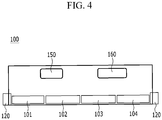
- FIG. 4 shows a top plan view of a device for manufacturing an electrode assembly of FIG. 3 .
- the device 100 for manufacturing an electrode assembly includes a winding portion 130, an electrode transfer line 140, air blowers 101, 102, 103, and 104, and an outlet 120.
- the air blowers 101, 102, 103, and 104 are installed on a top portion of the device 100 for manufacturing an electrode assembly, and blow air to a bottom portion of the device 100 for manufacturing an electrode assembly.
- the outlet 120 is installed in a lateral bottom end of the device 100 for manufacturing an electrode assembly so the air blown by the air blowers 101, 102, 103, and 104 is discharged with foreign particles.
- equipment such as an electrode fusion unit or an electrode inciser is not shown but is simplified.
- a portion where the device 100 for manufacturing an electrode assembly contacts a ground side may be referred to as the bottom portion, and a portion corresponding to the bottom portion of the manufacturing device 100 in an opposite direction to that of gravity may be referred to as the top portion.
- the air blowers 101, 102, 103, and 104 are installed in a direction in which the electrode transfer line 140 is transferred to prevent the foreign particles from arriving at the electrode by the air blown by the air blowers 101, 102, 103, and 104. Further, air cleanness around the winding portion 130 may be increased by mainly disposing the air blowers 101, 102, 103, and 104 on the top portion of the device 100 for manufacturing an electrode assembly corresponding to a position of the winding portion 130.
- At least one air blower 102 may be additionally disposed so that it may be provided on a same plane as the air blowers 101, 102, 103, and 104 and it may overlap the air blower 102 in a direction crossing a direction in which the electrode transfer line 140 is transferred.
- the outlet 120 may be installed below the electrode transfer line 140 to prevent the foreign particles from being input to the electrode transfer line 140 and the winding portion 130.
- the foreign particles generated by a power transmitter 150 and a power supply 160 installed on the rear side portion of the device 100 for manufacturing an electrode assembly may be prevented from being input to the electrode transfer line 140 and the winding portion 130 through an installing base hole 180.
- a rear side of the device 100 for manufacturing an electrode assembly may be a side corresponding to the front side of the device 100 for manufacturing an electrode assembly when the device 100 for manufacturing an electrode assembly is seen from the rear side.
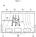
- FIG. 5 shows a front view of a flow of air in a device for manufacturing an electrode assembly of FIG. 3 .
- arrows indicate flows of air.
- the air blown by the air blowers 101, 102, 103, and 104 moves to the bottom portion of the device 100 for spirally winding an electrode assembly to the top portion thereof and is then discharged to the outlet 120 installed in the lateral bottom end of the device 100 for manufacturing an electrode assembly.
- the air blower 102 for blowing air toward the winding portion 130 may prevent foreign particles from being input to the winding portion 130 by blowing air with a relatively high flow rate.
- the air blowers 101, 102, 103, and 104 may blow dry air by including a moisture controlling function, and may include a filter function for filtering out foreign particles.
- the air blowers 101, 102, 103, and 104 may include a wind direction controlling function so that the air blown to the bottom portion of the device 100 for manufacturing an electrode assembly to the top portion thereof may be discharged to the outlet 120.
- the air blowers 101, 102, 103, and 104 include a wind speed controlling function to prevent foreign particles from being input to a specific part of the device 100 for manufacturing an electrode assembly by blowing air with a relative high wind speed to the specific part.
- the air blowers 101, 102, 103, and 104 are not specifically limited when they include the above-noted functions, and for example, an equipment fan filter unit may be used.
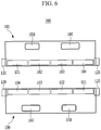
- FIG. 6 shows a top plan view of a system for manufacturing and installing an electrode assembly in which two units of a device for manufacturing an electrode assembly are provided to face each other according to FIG. 4 .
- the system for manufacturing and installing an electrode assembly includes two devices 100 for manufacturing an electrode assembly, and the two devices 100 for manufacturing an electrode assembly are installed in a same space to face each other.
- a range in which the air blowers 101, 102, 103, and 104 of the respective units are applied overlaps a space between the two devices 100 for manufacturing an electrode assembly, thereby increasing an air circulation effect.
- an operator may simultaneously manage the two devices 100 for manufacturing an electrode assembly, and may efficiently use the space in which the two devices 100 for manufacturing an electrode assembly are installed.
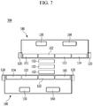
- FIG. 7 shows a top plan view of an exemplary variation of FIG. 6 .
- the two devices 100 for manufacturing an electrode assembly are installed in the same space to face each other, and the air blowers 102 for blowing air to the winding portion 130 are installed to face each other at the front.
- Air blowers 102 are additionally installed in the space between the air blowers 102 facing each other.
- at least one air blower 102 may be additionally disposed so that it may be provided on a same plane as the air blowers 101, 102, 103, and 104 and it may overlap the air blower 102 in a direction crossing a direction in which the electrode transfer line 140 is transferred.
- the air blown by the air blowers 102 may be gathered on the winding portion 101 to thereby increase air purity around the winding portion 101.
- FIG. 8 shows a top plan view of an exemplary variation of FIG. 7 .
- a system 400 for manufacturing and installing an electrode assembly corresponds to the structure shown in FIG. 7 except that the outlet 120 is installed on the respective sides of the space between the devices 100 for manufacturing an electrode assembly of two units. According to the above-noted configuration, the air gathered on the winding portion 101 may be more quickly discharged through the outlet 120.
- the device for manufacturing an electrode assembly shown in FIG. 5 is installed in a closed and sealed space, the device for manufacturing an electrode assembly is operated for one hour while the air blower and the outlet are turned on, and the generation level of foreign particles in a range of radius that is within 50 centimeters in the winding portion is determined. Numbers of foreign particles with diameters that are 0.5 micrometers, 1 micrometer, 5 micrometers, 10 micrometers, and 25 micrometers are measured. The number of foreign particles is measured for the respective diameters a total of six times each minute, and their mean value is found. The number of foreign particles is measured by using a particle counter.
- the particle counter used in the present examination is an Aerosol Particle Counter Lasair III 310B manufactured by PMS.
- the number of foreign particles is measured in the same condition as Example 1 except that the device for manufacturing an electrode assembly is operated for an hour while the air blower and the outlet are turned off.
- the number of environmental particles is measured at the height (corresponding to the height where the winding portion is positioned from the ground side) of about 1.5 meters from the ground side. Its measuring method is identical to that shown in Example 1.
- the total number of foreign particles in Example 1 is about 1/2000 compared to the total number of foreign particles of Comparative Example 1 to thus find that very few foreign particles are generated.
- the number of foreign particles of 0.5 micrometers of Example 1 is found to be generated as 1/3300 compared to Comparative Example 1.
- the foreign particles of 0.5 micrometers are considered to be major foreign particles that cause a short circuit and a low voltage in the process for manufacturing an electrode assembly, and they are found to be efficiently removed in the space in which the device for manufacturing an electrode assembly according to the present invention is utilized.
- Comparative Example 1 When the number of foreign particles of 0.5 micrometers of Comparative Example 1 is compared to the number of foreign particles of 0.5 micrometers of Comparative Example 2, it is found that Comparative Example 1 generates about twice the foreign particles as Comparative Example 2. They are foreign particles generated in the process for operating the device for manufacturing an electrode assembly, and the foreign particles, as found from Example 1, are efficiently removed when the air blower and the outlet according to the present invention are operated.
- the device for manufacturing an electrode assembly according to the present invention may prevent the foreign particles from being input to the winding portion by purifying air in the space where the device for manufacturing an electrode assembly is installed.
Landscapes
- Engineering & Computer Science (AREA)
- Manufacturing & Machinery (AREA)
- Chemical & Material Sciences (AREA)
- Chemical Kinetics & Catalysis (AREA)
- Electrochemistry (AREA)
- General Chemical & Material Sciences (AREA)
- Electrostatic Separation (AREA)
- Secondary Cells (AREA)
Abstract
Description
- This application claims priority to and the benefit of Korean Patent Application No.
10-2018-0082777 - The present invention relates to a device for manufacturing an electrode assembly with an air purifying function.
- Recently, price rise of energy sources caused by exhaustion of fossil fuels, and environmental contamination, have intensified, and demands for environmentally-friendly alternative sources of energy are becoming basic essentials for future life. Accordingly, studies on various electric power generating methods such as nuclear energy, solar power, wind power, and tidal power are in progress, and huge interest in electric power storing devices for more efficiently using energy produced in this way continues.
- Further, as technical developments and demands on mobile devices and cell vehicles increase, demands for batteries as an energy source substantially increase, and accordingly, many studies on batteries for satisfying various kinds of demands are currently being performed. Particularly, in the viewpoint of materials, there are high demands on lithium rechargeable batteries such as a lithium ion battery or a lithium ion polymer battery having merits including high energy density, a good discharging voltage, and output stability.
- The rechargeable batteries are classified depending on the structures of an electrode assembly in which a positive electrode, a negative electrode, and a separation film provided between the positive electrode and the negative electrode are stacked. Typical ones include a jelly roll type (winding type) of electrode assembly in which a long sheet type of positive electrode and negative electrode are wound while a separation film is provided, and a stacking type of electrode assembly in which a plurality of positive electrodes and negative electrodes cut to a predetermined size of unit are sequentially stacked while a separation film is provided, and recently, in order to solve the drawbacks of the jelly roll type of electrode assembly and the stacking type of electrode assembly, a stacking/folding type of electrode assembly in which unit cells in which positive electrodes and negative electrodes with a predetermined size are stacked while a separation film is provided are sequentially wound while provided on a separation film as an electrode assembly with an advanced structure that is a mixture of the jelly roll type and the stacking type is being developed.
- Among the electrode assemblies, the jelly roll type of electrode assembly has merits of easy manufacturing and high energy density per weight, so it is used as an energy source to various kinds of devices from laptop computers to cell vehicles.
-
FIG. 1 shows a front view of a conventional device for manufacturing a jelly roll type of electrode assembly.FIG. 2 shows a top plan view of a device for manufacturing an electrode assembly ofFIG. 1 . - Referring to
FIG. 1 andFIG. 2 , apositive electrode 11, anegative electrode 12, and aseparation film 13 are wound by a windingportion 14, so they are made into a jelly roll shape. In this instance, when foreign particles are input to thepositive electrode 11, thenegative electrode 12, and a surface of theseparation film 13 and are then wound altogether, drawbacks such as a low voltage or a short circuit are generated, so thedevice 10 for manufacturing an electrode assembly is operated in a space for closing and sealing out external air. - However, the
device 10 for manufacturing an electrode assembly includes various installations such as anelectrode transfer line 19, anelectrode coalescing unit 15, anelectrode incising unit 16, a power transmitter 17 (shown inFIG. 2 ), and a power supply 18 (shown inFIG. 2 ) in addition to thewinding portion 14, and various foreign particles are generated by operation of the installations. When the foreign particles are input into thewinding portion 14 and the foreign particles remain on thepositive electrode 11, thenegative electrode 12, and the surface of theseparation film 13, the foreign particles are wound together with thepositive electrode 11, thenegative electrode 12, and theseparation film 13, thereby causing problems such as the above-noted low voltage and the short circuit. - Further, the foreign particles generated by the operation of the power transmitter 17 (shown in
FIG. 2 ) and the power supply 18 (shown inFIG. 2 ) provided on a rear side of thedevice 10 for manufacturing an electrode assembly pass through abase hole 16 and are input to thewinding portion 14. To solve the problems, a method for installing an air blower at the front of thedevice 10 for manufacturing an electrode assembly, blowing air toward the rear side, and thus preventing foreign particles from being input to a front portion may be considered, but in this case, a moving line of a worker is disturbed, and provision of materials is difficult, so it is undesirable to install the air blower on the front side of themanufacturing device 10. - Therefore, there is a need for skills for fundamentally solving the problem.
- An object of the present invention is to solve the problems of the prior art and technical problems from the past.
- The inventors of the present invention, having performed in-depth research and experimentation, confirmed prevention of foreign particles from being input to a winding portion by installing an air blower in a top portion of a device for manufacturing an electrode assembly, and installing an outlet in a lateral bottom end portion of the device for manufacturing an electrode assembly, and completed the present invention.
- An exemplary embodiment of the present invention provides a device for manufacturing an electrode assembly for removing foreign particles through air circulation, including: a winding portion; an electrode transfer line; an air blower installed on a top portion of the device for manufacturing an electrode assembly and blowing air to a bottom portion of the device for manufacturing an electrode assembly; and an outlet for discharging air moved to the bottom portion by the air blower.
- The air blower may be installed in a transfer direction of the electrode transfer line.
- Regarding the air blower, at least one air blower may be further installed to overlap the air blower in a direction crossing a direction in which the electrode transfer line is transferred on the upper portion corresponding to the winding portion.
- The outlet may be installed below the electrode transfer line.
- The outlet may be installed on a lateral bottom end portion of the device for manufacturing an electrode assembly.
- Another embodiment of the present invention provides a system for manufacturing and installing an electrode assembly, wherein a device for manufacturing an electrode assembly includes a first device for manufacturing an electrode assembly and a second device for manufacturing an electrode assembly, and the first device for manufacturing an electrode assembly and the second device for manufacturing an electrode assembly are installed to face each other.
- A first air blower for blowing air to a winding portion of the first device for manufacturing an electrode assembly and a second air blower for blowing air to a winding portion of the second device for manufacturing an electrode assembly may be installed to face each other at a front.
- At least one air blower may be installed so that the electrode transfer line may overlap the first air blower and the second air blower in a direction crossing a transferring direction between the first air blower and the second air blower.
- An outlet may be installed on respective sides of a space between the first device for manufacturing an electrode assembly and the second device for manufacturing an electrode assembly.
-
-
FIG. 1 shows a front view of a conventional device for manufacturing a jelly roll type of electrode assembly. -
FIG. 2 shows a top plan view of a device for manufacturing an electrode assembly ofFIG. 1 . -
FIG. 3 shows a front view of a device for manufacturing an electrode assembly according to an exemplary embodiment of the present invention. -
FIG. 4 shows a top plan view of a device for manufacturing an electrode assembly ofFIG. 3 . -
FIG. 5 shows a front view of a flow of air in a device for manufacturing an electrode assembly ofFIG. 3 . -
FIG. 6 shows a top plan view of a system for manufacturing and installing an electrode assembly in which two units of a device for manufacturing an electrode assembly are provided to face each other according toFIG. 3 . -
FIG. 7 shows a top plan view of an exemplary variation ofFIG. 6 . -
FIG. 8 shows a top plan view of an exemplary variation ofFIG. 7 . - The present invention will be described more fully hereinafter with reference to the accompanying drawings, in which exemplary embodiments of the invention are shown. As those skilled in the art would realize, the described embodiments may be modified in various different ways, all without departing from the spirit or scope of the present invention.
- Unless explicitly described to the contrary, the word "comprise" and variations such as "comprises" or "comprising" will be understood to imply the inclusion of stated elements but not the exclusion of any other elements.
- Further, in the specification, the phrase "on a plane" means viewing the object portion from the top, and the phrase "in a front view" means viewing a cross-section of which the object portion is visible from the front.
-
FIG. 3 shows a front view of a device for manufacturing an electrode assembly according to an exemplary embodiment of the present invention.FIG. 4 shows a top plan view of a device for manufacturing an electrode assembly ofFIG. 3 . - Referring to
FIG. 3 andFIG. 4 , thedevice 100 for manufacturing an electrode assembly includes awinding portion 130, anelectrode transfer line 140,air blowers outlet 120. Theair blowers device 100 for manufacturing an electrode assembly, and blow air to a bottom portion of thedevice 100 for manufacturing an electrode assembly. Theoutlet 120 is installed in a lateral bottom end of thedevice 100 for manufacturing an electrode assembly so the air blown by theair blowers device 100 for spirally winding an electrode assembly, equipment such as an electrode fusion unit or an electrode inciser is not shown but is simplified. Here, regarding a top portion and a bottom portion of thedevice 100 for manufacturing an electrode assembly, a portion where thedevice 100 for manufacturing an electrode assembly contacts a ground side may be referred to as the bottom portion, and a portion corresponding to the bottom portion of themanufacturing device 100 in an opposite direction to that of gravity may be referred to as the top portion. - The
air blowers electrode transfer line 140 is transferred to prevent the foreign particles from arriving at the electrode by the air blown by theair blowers winding portion 130 may be increased by mainly disposing theair blowers device 100 for manufacturing an electrode assembly corresponding to a position of thewinding portion 130. In detail, at least oneair blower 102 may be additionally disposed so that it may be provided on a same plane as theair blowers air blower 102 in a direction crossing a direction in which theelectrode transfer line 140 is transferred. - Further, the
outlet 120 may be installed below theelectrode transfer line 140 to prevent the foreign particles from being input to theelectrode transfer line 140 and thewinding portion 130. Particularly, the foreign particles generated by apower transmitter 150 and apower supply 160 installed on the rear side portion of thedevice 100 for manufacturing an electrode assembly may be prevented from being input to theelectrode transfer line 140 and thewinding portion 130 through aninstalling base hole 180. Here, a rear side of thedevice 100 for manufacturing an electrode assembly may be a side corresponding to the front side of thedevice 100 for manufacturing an electrode assembly when thedevice 100 for manufacturing an electrode assembly is seen from the rear side. -
FIG. 5 shows a front view of a flow of air in a device for manufacturing an electrode assembly ofFIG. 3 . - Referring to
FIG. 3 andFIG. 5 , arrows indicate flows of air. The air blown by theair blowers device 100 for spirally winding an electrode assembly to the top portion thereof and is then discharged to theoutlet 120 installed in the lateral bottom end of thedevice 100 for manufacturing an electrode assembly. - The
air blower 102 for blowing air toward the windingportion 130 may prevent foreign particles from being input to the windingportion 130 by blowing air with a relatively high flow rate. - The
air blowers air blowers device 100 for manufacturing an electrode assembly to the top portion thereof may be discharged to theoutlet 120. Further, theair blowers device 100 for manufacturing an electrode assembly by blowing air with a relative high wind speed to the specific part. Theair blowers -
FIG. 6 shows a top plan view of a system for manufacturing and installing an electrode assembly in which two units of a device for manufacturing an electrode assembly are provided to face each other according toFIG. 4 . - Referring to
FIG. 4 andFIG. 6 , the system for manufacturing and installing an electrode assembly includes twodevices 100 for manufacturing an electrode assembly, and the twodevices 100 for manufacturing an electrode assembly are installed in a same space to face each other. In this case, a range in which theair blowers devices 100 for manufacturing an electrode assembly, thereby increasing an air circulation effect. Further, in the space between the twodevices 100 for manufacturing an electrode assembly, an operator may simultaneously manage the twodevices 100 for manufacturing an electrode assembly, and may efficiently use the space in which the twodevices 100 for manufacturing an electrode assembly are installed. -
FIG. 7 shows a top plan view of an exemplary variation ofFIG. 6 . - Referring to
FIG. 3 ,FIG. 6 , andFIG. 7 , regarding asystem 300 for manufacturing and installing an electrode assembly, the twodevices 100 for manufacturing an electrode assembly are installed in the same space to face each other, and theair blowers 102 for blowing air to the windingportion 130 are installed to face each other at the front.Air blowers 102 are additionally installed in the space between theair blowers 102 facing each other. In detail, at least oneair blower 102 may be additionally disposed so that it may be provided on a same plane as theair blowers air blower 102 in a direction crossing a direction in which theelectrode transfer line 140 is transferred. - By the above-described structure, the air blown by the
air blowers 102 may be gathered on the windingportion 101 to thereby increase air purity around the windingportion 101. -
FIG. 8 shows a top plan view of an exemplary variation ofFIG. 7 . - Referring to
FIG. 3 ,FIG. 7 , andFIG. 8 , asystem 400 for manufacturing and installing an electrode assembly corresponds to the structure shown inFIG. 7 except that theoutlet 120 is installed on the respective sides of the space between thedevices 100 for manufacturing an electrode assembly of two units. According to the above-noted configuration, the air gathered on the windingportion 101 may be more quickly discharged through theoutlet 120. - Generation levels for respective diameters of foreign particles are examined in the space in which the device for manufacturing an electrode assembly according to the present invention is installed.
- The device for manufacturing an electrode assembly shown in
FIG. 5 is installed in a closed and sealed space, the device for manufacturing an electrode assembly is operated for one hour while the air blower and the outlet are turned on, and the generation level of foreign particles in a range of radius that is within 50 centimeters in the winding portion is determined. Numbers of foreign particles with diameters that are 0.5 micrometers, 1 micrometer, 5 micrometers, 10 micrometers, and 25 micrometers are measured. The number of foreign particles is measured for the respective diameters a total of six times each minute, and their mean value is found. The number of foreign particles is measured by using a particle counter. The particle counter used in the present examination is an Aerosol Particle Counter Lasair III 310B manufactured by PMS. - The number of foreign particles is measured in the same condition as Example 1 except that the device for manufacturing an electrode assembly is operated for an hour while the air blower and the outlet are turned off.
- In an external space, the number of environmental particles is measured at the height (corresponding to the height where the winding portion is positioned from the ground side) of about 1.5 meters from the ground side. Its measuring method is identical to that shown in Example 1.
[Table 1] Number of measurements (number of times/minute) Mean value of number of foreign particles for respective diameters (micrometers) 0.5 1 5 10 25 Total number Example 1 6 189 136 9 4 0 338 Comparative Example 1 6 627,323 43,092 682 58 9 671,163 Comparative Example 2 5 360,682 29,150 1,234 367 3 391,468 - The total number of foreign particles in Example 1 is about 1/2000 compared to the total number of foreign particles of Comparative Example 1 to thus find that very few foreign particles are generated. Particularly, the number of foreign particles of 0.5 micrometers of Example 1 is found to be generated as 1/3300 compared to Comparative Example 1. The foreign particles of 0.5 micrometers are considered to be major foreign particles that cause a short circuit and a low voltage in the process for manufacturing an electrode assembly, and they are found to be efficiently removed in the space in which the device for manufacturing an electrode assembly according to the present invention is utilized.
- When the number of foreign particles of 0.5 micrometers of Comparative Example 1 is compared to the number of foreign particles of 0.5 micrometers of Comparative Example 2, it is found that Comparative Example 1 generates about twice the foreign particles as Comparative Example 2. They are foreign particles generated in the process for operating the device for manufacturing an electrode assembly, and the foreign particles, as found from Example 1, are efficiently removed when the air blower and the outlet according to the present invention are operated.
- Those of ordinary skill in the art to which the present invention belongs will be able to make various applications and modifications within the scope of the present invention.
- The device for manufacturing an electrode assembly according to the present invention may prevent the foreign particles from being input to the winding portion by purifying air in the space where the device for manufacturing an electrode assembly is installed.
Claims (9)
- A device for manufacturing an electrode assembly for removing foreign particles through air circulation, comprising:a winding portion;an electrode transfer line;an air blower installed on a top portion of the device for manufacturing an electrode assembly and blowing air to a bottom portion of the device for manufacturing an electrode assembly; andan outlet for discharging air moved to the bottom portion by the air blower.
- The device of claim 1, wherein
the air blower is installed in a transfer direction of the electrode transfer line. - The device of claim 1, wherein
regarding the air blower, at least one air blower is further installed to overlap the air blower in a direction crossing a direction in which the electrode transfer line is transferred on the upper portion corresponding to the winding portion. - The device of claim 1, wherein
the outlet is installed below the electrode transfer line. - The device of claim 1, wherein
the outlet is installed on a lateral bottom end portion of the device for manufacturing an electrode assembly. - A system for manufacturing and installing an electrode assembly, wherein a device for manufacturing an electrode assembly of Claim 1 includes a first device for manufacturing an electrode assembly and a second device for manufacturing an electrode assembly, and the first device for manufacturing an electrode assembly and the second device for manufacturing an electrode assembly are installed to face each other.
- The system of claim 6, wherein
a first air blower for blowing air to a winding portion of the first device for manufacturing an electrode assembly and a second air blower for blowing air to a winding portion of the second device for manufacturing an electrode assembly are installed to face each other at a front. - The system of claim 7, wherein
at least one air blower is installed so that the electrode transfer line may overlap the first air blower and the second air blower in a direction crossing a transferring direction between the first air blower and the second air blower. - The system of claim 6, wherein
an outlet is installed on respective sides of a space between the first device for manufacturing an electrode assembly and the second device for manufacturing an electrode assembly.
Applications Claiming Priority (2)
| Application Number | Priority Date | Filing Date | Title |
|---|---|---|---|
| KR1020180082777A KR102628794B1 (en) | 2018-07-17 | 2018-07-17 | Electrode assembly manufacfuring device having air purification |
| PCT/KR2019/008434 WO2020017809A1 (en) | 2018-07-17 | 2019-07-09 | Electrode assembly manufacturing apparatus equipped with air purifying function |
Publications (3)
| Publication Number | Publication Date |
|---|---|
| EP3747548A1 true EP3747548A1 (en) | 2020-12-09 |
| EP3747548A4 EP3747548A4 (en) | 2021-04-14 |
| EP3747548B1 EP3747548B1 (en) | 2023-09-27 |
Family
ID=69164486
Family Applications (1)
| Application Number | Title | Priority Date | Filing Date |
|---|---|---|---|
| EP19838168.3A Active EP3747548B1 (en) | 2018-07-17 | 2019-07-09 | Device for manufacturing electrode assembly with air purification function |
Country Status (9)
| Country | Link |
|---|---|
| US (1) | US11769898B2 (en) |
| EP (1) | EP3747548B1 (en) |
| JP (1) | JP7051034B2 (en) |
| KR (1) | KR102628794B1 (en) |
| CN (1) | CN111757781B (en) |
| ES (1) | ES2960977T3 (en) |
| HU (1) | HUE063666T2 (en) |
| PL (1) | PL3747548T3 (en) |
| WO (1) | WO2020017809A1 (en) |
Families Citing this family (2)
| Publication number | Priority date | Publication date | Assignee | Title |
|---|---|---|---|---|
| KR102940102B1 (en) * | 2021-11-24 | 2026-03-16 | 주식회사 엘지에너지솔루션 | Formation device for battery cells |
| KR20230097729A (en) | 2021-12-24 | 2023-07-03 | 주식회사 엘지에너지솔루션 | Electrode assembly transport system |
Family Cites Families (26)
| Publication number | Priority date | Publication date | Assignee | Title |
|---|---|---|---|---|
| SE517541C2 (en) | 1996-06-04 | 2002-06-18 | Eurus Airtech Ab | Air purification device |
| US6019848A (en) * | 1996-11-13 | 2000-02-01 | Applied Materials, Inc. | Lid assembly for high temperature processing chamber |
| JPH11329416A (en) * | 1998-05-14 | 1999-11-30 | Toyota Central Res & Dev Lab Inc | Manufacturing method of sheet electrode |
| JP2000030700A (en) * | 1998-07-13 | 2000-01-28 | Ishikawajima Harima Heavy Ind Co Ltd | Negative electrode substrate for nickel-hydrogen battery and method of manufacturing the same |
| KR200215592Y1 (en) | 2000-09-28 | 2001-03-15 | 주식회사이스퀘어텍 | Manufacturing System for Jelly Roll of Lithium Reusable Battery |
| JP2004195399A (en) | 2002-12-19 | 2004-07-15 | Sony Corp | Cleaning apparatus and cleaning method for band-shaped body |
| JP4964818B2 (en) * | 2008-04-04 | 2012-07-04 | シーケーディ株式会社 | Winding element manufacturing equipment |
| KR101475429B1 (en) * | 2012-05-15 | 2014-12-23 | 주식회사 엘지화학 | Flow Controller of Drying Oven with Automatic Air Charge for Manufacturing Secondary Battery |
| KR101564537B1 (en) * | 2012-12-05 | 2015-10-29 | 닛산 지도우샤 가부시키가이샤 | Electrical device separator severing apparatus and severing method |
| CN202962974U (en) | 2012-12-20 | 2013-06-05 | 钱和革 | Dust collection mechanism of battery winding machine |
| KR102007698B1 (en) * | 2013-01-23 | 2019-08-06 | 삼성에스디아이 주식회사 | Dryer for electrode substrate of rechargeable battery and controlling method of the same |
| AU2015257899B2 (en) | 2014-05-09 | 2018-07-05 | Basf Se | Articles produced by thermoforming |
| KR101763453B1 (en) * | 2014-07-24 | 2017-07-31 | 주식회사 엘지화학 | Winding apparatus of electrode assembly |
| JP6392457B2 (en) * | 2015-11-13 | 2018-09-19 | エルジー・ケム・リミテッド | ABS resin composition and molded article produced therefrom |
| KR102126764B1 (en) * | 2016-03-15 | 2020-06-25 | 주식회사 엘지화학 | Impurity Removing Device Having Structure of Antispattering |
| CN105797853B (en) * | 2016-06-08 | 2018-03-27 | 佛山市顺德区拓维电器有限公司 | A kind of efficient absorption air cleaning unit and air purifier |
| JP2018018681A (en) * | 2016-07-27 | 2018-02-01 | 株式会社豊田自動織機 | Electrode manufacturing device and electrode manufacturing method |
| WO2018025785A1 (en) * | 2016-08-04 | 2018-02-08 | 帝人株式会社 | Winding core, device for manufacturing wound electrode, and method for manufacturing wound electrode |
| PL3370292T3 (en) * | 2016-08-26 | 2022-01-03 | Lg Chem, Ltd. | Device for manufacturing electrode assembly including air blowing unit |
| US10254043B2 (en) | 2016-09-22 | 2019-04-09 | Grst International Limited | Method of drying electrode assemblies |
| JP6530360B2 (en) * | 2016-09-23 | 2019-06-12 | 株式会社東芝 | Photoelectric conversion element |
| KR102277230B1 (en) * | 2017-01-03 | 2021-07-14 | 주식회사 엘지에너지솔루션 | Device for Drying Electrode Comprising Un-winder and Re-winder |
| KR20180082777A (en) | 2017-01-11 | 2018-07-19 | 한국기술교육대학교 산학협력단 | Communion robot system for senior citizen |
| CN206758566U (en) * | 2017-04-06 | 2017-12-15 | 浙江和泽电子科技有限公司 | A kind of battery winder with dedusting function |
| CN107403962A (en) * | 2017-07-21 | 2017-11-28 | 福建猛狮新能源科技有限公司 | Battery core dust exhaust apparatus for lithium battery automatic winding-machine |
| CN108172910B (en) * | 2018-03-02 | 2023-11-24 | 江西迪比科股份有限公司 | Multifunctional lithium battery winding machine |
-
2018
- 2018-07-17 KR KR1020180082777A patent/KR102628794B1/en active Active
-
2019
- 2019-07-09 HU HUE19838168A patent/HUE063666T2/en unknown
- 2019-07-09 JP JP2020542443A patent/JP7051034B2/en active Active
- 2019-07-09 ES ES19838168T patent/ES2960977T3/en active Active
- 2019-07-09 WO PCT/KR2019/008434 patent/WO2020017809A1/en not_active Ceased
- 2019-07-09 EP EP19838168.3A patent/EP3747548B1/en active Active
- 2019-07-09 PL PL19838168.3T patent/PL3747548T3/en unknown
- 2019-07-09 US US16/971,184 patent/US11769898B2/en active Active
- 2019-07-09 CN CN201980014703.0A patent/CN111757781B/en active Active
Also Published As
| Publication number | Publication date |
|---|---|
| ES2960977T3 (en) | 2024-03-07 |
| HUE063666T2 (en) | 2024-01-28 |
| CN111757781A (en) | 2020-10-09 |
| US20210101159A1 (en) | 2021-04-08 |
| EP3747548A4 (en) | 2021-04-14 |
| WO2020017809A1 (en) | 2020-01-23 |
| KR20200008741A (en) | 2020-01-29 |
| US11769898B2 (en) | 2023-09-26 |
| PL3747548T3 (en) | 2024-01-22 |
| CN111757781B (en) | 2022-07-12 |
| JP2021514098A (en) | 2021-06-03 |
| EP3747548B1 (en) | 2023-09-27 |
| KR102628794B1 (en) | 2024-01-23 |
| JP7051034B2 (en) | 2022-04-11 |
Similar Documents
| Publication | Publication Date | Title |
|---|---|---|
| KR101475429B1 (en) | Flow Controller of Drying Oven with Automatic Air Charge for Manufacturing Secondary Battery | |
| KR102026126B1 (en) | Device for Manufacturing Electrode Comprising Notching Roller | |
| Munshi et al. | Performance of polymer electrolyte cells at+ 25 to+ 100° C | |
| EP3747548B1 (en) | Device for manufacturing electrode assembly with air purification function | |
| US10974285B2 (en) | Device comprising cleaning roll and for cleaning protective film for preparing battery cell | |
| CN114649557A (en) | Apparatus for manufacturing battery cell | |
| KR20170053892A (en) | Electrode Sheet Manufacturing Apparatus Providing Improved Productivity by Simultaneous Performance of Slitting and Coating | |
| US20220294063A1 (en) | Battery transporting apparatus | |
| CN107046117A (en) | A kind of corona treatment plant and its application for lithium ion battery separator or basement membrane | |
| KR102065084B1 (en) | Device for Cutting Electrode Sheet Capable of Removing Foreign Material | |
| US11916182B2 (en) | Winding device for manufacturing electrode assembly | |
| WO2020189994A1 (en) | Battery manufacturing device and manufacturing method for battery | |
| KR101500548B1 (en) | Secondary battery rack housing for enhencing efficient use of space, power storage unit comprising the same, array of rack housing comprising the same and power storage system comprising the same | |
| EP3817091A1 (en) | Apparatus for manufacturing battery pack and method for manufacturing battery pack | |
| KR102731449B1 (en) | Device for manufacturing cylindrical battery | |
| EP3399581A1 (en) | Cleaning device, provided with cleaning roll, for protective film for battery cell production | |
| US20220080451A1 (en) | Slot Die Coating Device Having Air Vent | |
| KR20150121912A (en) | Pouch penetration apparatus for gas discharge of pouch type secondary battery | |
| US12266816B2 (en) | Battery transport apparatus | |
| KR20180125313A (en) | Energy storage apparatus | |
| CN221134518U (en) | Pole piece cutting device and battery cell production system | |
| CN205595382U (en) | A lithium cell group for wireless hand vacuum cleaner | |
| KR102608817B1 (en) | Heating roller unit for manufacturing secondary batteries and secondary battery stacking equipment having the same | |
| CN202823990U (en) | Dust removal device for lithium battery production | |
| CN104475611A (en) | Dedusting process and receiving device suitable for lithium ion battery pole pieces |
Legal Events
| Date | Code | Title | Description |
|---|---|---|---|
| STAA | Information on the status of an ep patent application or granted ep patent |
Free format text: STATUS: THE INTERNATIONAL PUBLICATION HAS BEEN MADE |
|
| PUAI | Public reference made under article 153(3) epc to a published international application that has entered the european phase |
Free format text: ORIGINAL CODE: 0009012 |
|
| STAA | Information on the status of an ep patent application or granted ep patent |
Free format text: STATUS: REQUEST FOR EXAMINATION WAS MADE |
|
| 17P | Request for examination filed |
Effective date: 20200902 |
|
| AK | Designated contracting states |
Kind code of ref document: A1 Designated state(s): AL AT BE BG CH CY CZ DE DK EE ES FI FR GB GR HR HU IE IS IT LI LT LU LV MC MK MT NL NO PL PT RO RS SE SI SK SM TR |
|
| AX | Request for extension of the european patent |
Extension state: BA ME |
|
| A4 | Supplementary search report drawn up and despatched |
Effective date: 20210317 |
|
| RIC1 | Information provided on ipc code assigned before grant |
Ipc: H01M 10/04 20060101AFI20210311BHEP |
|
| DAV | Request for validation of the european patent (deleted) | ||
| DAX | Request for extension of the european patent (deleted) | ||
| RAP1 | Party data changed (applicant data changed or rights of an application transferred) |
Owner name: LG ENERGY SOLUTION LTD. |
|
| RAP3 | Party data changed (applicant data changed or rights of an application transferred) |
Owner name: LG ENERGY SOLUTION, LTD. |
|
| REG | Reference to a national code |
Ref country code: DE Ref legal event code: R079 Free format text: PREVIOUS MAIN CLASS: B03C0003400000 Ipc: H01M0010040000 Ref country code: DE Ref legal event code: R079 Ref document number: 602019038361 Country of ref document: DE Free format text: PREVIOUS MAIN CLASS: B03C0003400000 Ipc: H01M0010040000 |
|
| RIC1 | Information provided on ipc code assigned before grant |
Ipc: B65H 18/00 20060101ALI20230303BHEP Ipc: H01M 10/04 20060101AFI20230303BHEP |
|
| GRAP | Despatch of communication of intention to grant a patent |
Free format text: ORIGINAL CODE: EPIDOSNIGR1 |
|
| STAA | Information on the status of an ep patent application or granted ep patent |
Free format text: STATUS: GRANT OF PATENT IS INTENDED |
|
| INTG | Intention to grant announced |
Effective date: 20230420 |
|
| P01 | Opt-out of the competence of the unified patent court (upc) registered |
Effective date: 20230516 |
|
| GRAS | Grant fee paid |
Free format text: ORIGINAL CODE: EPIDOSNIGR3 |
|
| GRAA | (expected) grant |
Free format text: ORIGINAL CODE: 0009210 |
|
| STAA | Information on the status of an ep patent application or granted ep patent |
Free format text: STATUS: THE PATENT HAS BEEN GRANTED |
|
| AK | Designated contracting states |
Kind code of ref document: B1 Designated state(s): AL AT BE BG CH CY CZ DE DK EE ES FI FR GB GR HR HU IE IS IT LI LT LU LV MC MK MT NL NO PL PT RO RS SE SI SK SM TR |
|
| REG | Reference to a national code |
Ref country code: GB Ref legal event code: FG4D |
|
| REG | Reference to a national code |
Ref country code: CH Ref legal event code: EP |
|
| REG | Reference to a national code |
Ref country code: DE Ref legal event code: R096 Ref document number: 602019038361 Country of ref document: DE |
|
| REG | Reference to a national code |
Ref country code: IE Ref legal event code: FG4D |
|
| REG | Reference to a national code |
Ref country code: SE Ref legal event code: TRGR |
|
| REG | Reference to a national code |
Ref country code: LT Ref legal event code: MG9D |
|
| PG25 | Lapsed in a contracting state [announced via postgrant information from national office to epo] |
Ref country code: GR Free format text: LAPSE BECAUSE OF FAILURE TO SUBMIT A TRANSLATION OF THE DESCRIPTION OR TO PAY THE FEE WITHIN THE PRESCRIBED TIME-LIMIT Effective date: 20231228 |
|
| REG | Reference to a national code |
Ref country code: HU Ref legal event code: AG4A Ref document number: E063666 Country of ref document: HU |
|
| PG25 | Lapsed in a contracting state [announced via postgrant information from national office to epo] |
Ref country code: RS Free format text: LAPSE BECAUSE OF FAILURE TO SUBMIT A TRANSLATION OF THE DESCRIPTION OR TO PAY THE FEE WITHIN THE PRESCRIBED TIME-LIMIT Effective date: 20230927 Ref country code: NO Free format text: LAPSE BECAUSE OF FAILURE TO SUBMIT A TRANSLATION OF THE DESCRIPTION OR TO PAY THE FEE WITHIN THE PRESCRIBED TIME-LIMIT Effective date: 20231227 Ref country code: LV Free format text: LAPSE BECAUSE OF FAILURE TO SUBMIT A TRANSLATION OF THE DESCRIPTION OR TO PAY THE FEE WITHIN THE PRESCRIBED TIME-LIMIT Effective date: 20230927 Ref country code: LT Free format text: LAPSE BECAUSE OF FAILURE TO SUBMIT A TRANSLATION OF THE DESCRIPTION OR TO PAY THE FEE WITHIN THE PRESCRIBED TIME-LIMIT Effective date: 20230927 Ref country code: HR Free format text: LAPSE BECAUSE OF FAILURE TO SUBMIT A TRANSLATION OF THE DESCRIPTION OR TO PAY THE FEE WITHIN THE PRESCRIBED TIME-LIMIT Effective date: 20230927 Ref country code: GR Free format text: LAPSE BECAUSE OF FAILURE TO SUBMIT A TRANSLATION OF THE DESCRIPTION OR TO PAY THE FEE WITHIN THE PRESCRIBED TIME-LIMIT Effective date: 20231228 Ref country code: FI Free format text: LAPSE BECAUSE OF FAILURE TO SUBMIT A TRANSLATION OF THE DESCRIPTION OR TO PAY THE FEE WITHIN THE PRESCRIBED TIME-LIMIT Effective date: 20230927 |
|
| REG | Reference to a national code |
Ref country code: NL Ref legal event code: MP Effective date: 20230927 |
|
| REG | Reference to a national code |
Ref country code: AT Ref legal event code: MK05 Ref document number: 1616320 Country of ref document: AT Kind code of ref document: T Effective date: 20230927 |
|
| PG25 | Lapsed in a contracting state [announced via postgrant information from national office to epo] |
Ref country code: NL Free format text: LAPSE BECAUSE OF FAILURE TO SUBMIT A TRANSLATION OF THE DESCRIPTION OR TO PAY THE FEE WITHIN THE PRESCRIBED TIME-LIMIT Effective date: 20230927 |
|
| REG | Reference to a national code |
Ref country code: ES Ref legal event code: FG2A Ref document number: 2960977 Country of ref document: ES Kind code of ref document: T3 Effective date: 20240307 |
|
| PG25 | Lapsed in a contracting state [announced via postgrant information from national office to epo] |
Ref country code: IS Free format text: LAPSE BECAUSE OF FAILURE TO SUBMIT A TRANSLATION OF THE DESCRIPTION OR TO PAY THE FEE WITHIN THE PRESCRIBED TIME-LIMIT Effective date: 20240127 |
|
| PG25 | Lapsed in a contracting state [announced via postgrant information from national office to epo] |
Ref country code: AT Free format text: LAPSE BECAUSE OF FAILURE TO SUBMIT A TRANSLATION OF THE DESCRIPTION OR TO PAY THE FEE WITHIN THE PRESCRIBED TIME-LIMIT Effective date: 20230927 |
|
| PG25 | Lapsed in a contracting state [announced via postgrant information from national office to epo] |
Ref country code: SM Free format text: LAPSE BECAUSE OF FAILURE TO SUBMIT A TRANSLATION OF THE DESCRIPTION OR TO PAY THE FEE WITHIN THE PRESCRIBED TIME-LIMIT Effective date: 20230927 Ref country code: RO Free format text: LAPSE BECAUSE OF FAILURE TO SUBMIT A TRANSLATION OF THE DESCRIPTION OR TO PAY THE FEE WITHIN THE PRESCRIBED TIME-LIMIT Effective date: 20230927 Ref country code: IS Free format text: LAPSE BECAUSE OF FAILURE TO SUBMIT A TRANSLATION OF THE DESCRIPTION OR TO PAY THE FEE WITHIN THE PRESCRIBED TIME-LIMIT Effective date: 20240127 Ref country code: EE Free format text: LAPSE BECAUSE OF FAILURE TO SUBMIT A TRANSLATION OF THE DESCRIPTION OR TO PAY THE FEE WITHIN THE PRESCRIBED TIME-LIMIT Effective date: 20230927 Ref country code: CZ Free format text: LAPSE BECAUSE OF FAILURE TO SUBMIT A TRANSLATION OF THE DESCRIPTION OR TO PAY THE FEE WITHIN THE PRESCRIBED TIME-LIMIT Effective date: 20230927 Ref country code: AT Free format text: LAPSE BECAUSE OF FAILURE TO SUBMIT A TRANSLATION OF THE DESCRIPTION OR TO PAY THE FEE WITHIN THE PRESCRIBED TIME-LIMIT Effective date: 20230927 Ref country code: PT Free format text: LAPSE BECAUSE OF FAILURE TO SUBMIT A TRANSLATION OF THE DESCRIPTION OR TO PAY THE FEE WITHIN THE PRESCRIBED TIME-LIMIT Effective date: 20240129 Ref country code: SK Free format text: LAPSE BECAUSE OF FAILURE TO SUBMIT A TRANSLATION OF THE DESCRIPTION OR TO PAY THE FEE WITHIN THE PRESCRIBED TIME-LIMIT Effective date: 20230927 |
|
| PG25 | Lapsed in a contracting state [announced via postgrant information from national office to epo] |
Ref country code: IT Free format text: LAPSE BECAUSE OF FAILURE TO SUBMIT A TRANSLATION OF THE DESCRIPTION OR TO PAY THE FEE WITHIN THE PRESCRIBED TIME-LIMIT Effective date: 20230927 |
|
| REG | Reference to a national code |
Ref country code: DE Ref legal event code: R097 Ref document number: 602019038361 Country of ref document: DE |
|
| PG25 | Lapsed in a contracting state [announced via postgrant information from national office to epo] |
Ref country code: DK Free format text: LAPSE BECAUSE OF FAILURE TO SUBMIT A TRANSLATION OF THE DESCRIPTION OR TO PAY THE FEE WITHIN THE PRESCRIBED TIME-LIMIT Effective date: 20230927 |
|
| PG25 | Lapsed in a contracting state [announced via postgrant information from national office to epo] |
Ref country code: DK Free format text: LAPSE BECAUSE OF FAILURE TO SUBMIT A TRANSLATION OF THE DESCRIPTION OR TO PAY THE FEE WITHIN THE PRESCRIBED TIME-LIMIT Effective date: 20230927 |
|
| PLBE | No opposition filed within time limit |
Free format text: ORIGINAL CODE: 0009261 |
|
| STAA | Information on the status of an ep patent application or granted ep patent |
Free format text: STATUS: NO OPPOSITION FILED WITHIN TIME LIMIT |
|
| 26N | No opposition filed |
Effective date: 20240628 |
|
| PG25 | Lapsed in a contracting state [announced via postgrant information from national office to epo] |
Ref country code: SI Free format text: LAPSE BECAUSE OF FAILURE TO SUBMIT A TRANSLATION OF THE DESCRIPTION OR TO PAY THE FEE WITHIN THE PRESCRIBED TIME-LIMIT Effective date: 20230927 |
|
| PG25 | Lapsed in a contracting state [announced via postgrant information from national office to epo] |
Ref country code: SI Free format text: LAPSE BECAUSE OF FAILURE TO SUBMIT A TRANSLATION OF THE DESCRIPTION OR TO PAY THE FEE WITHIN THE PRESCRIBED TIME-LIMIT Effective date: 20230927 |
|
| PG25 | Lapsed in a contracting state [announced via postgrant information from national office to epo] |
Ref country code: BG Free format text: LAPSE BECAUSE OF FAILURE TO SUBMIT A TRANSLATION OF THE DESCRIPTION OR TO PAY THE FEE WITHIN THE PRESCRIBED TIME-LIMIT Effective date: 20230927 |
|
| PG25 | Lapsed in a contracting state [announced via postgrant information from national office to epo] |
Ref country code: BG Free format text: LAPSE BECAUSE OF FAILURE TO SUBMIT A TRANSLATION OF THE DESCRIPTION OR TO PAY THE FEE WITHIN THE PRESCRIBED TIME-LIMIT Effective date: 20230927 |
|
| PG25 | Lapsed in a contracting state [announced via postgrant information from national office to epo] |
Ref country code: MC Free format text: LAPSE BECAUSE OF FAILURE TO SUBMIT A TRANSLATION OF THE DESCRIPTION OR TO PAY THE FEE WITHIN THE PRESCRIBED TIME-LIMIT Effective date: 20230927 |
|
| REG | Reference to a national code |
Ref country code: CH Ref legal event code: PL |
|
| PG25 | Lapsed in a contracting state [announced via postgrant information from national office to epo] |
Ref country code: LU Free format text: LAPSE BECAUSE OF NON-PAYMENT OF DUE FEES Effective date: 20240709 |
|
| PG25 | Lapsed in a contracting state [announced via postgrant information from national office to epo] |
Ref country code: LU Free format text: LAPSE BECAUSE OF NON-PAYMENT OF DUE FEES Effective date: 20240709 |
|
| PG25 | Lapsed in a contracting state [announced via postgrant information from national office to epo] |
Ref country code: CH Free format text: LAPSE BECAUSE OF NON-PAYMENT OF DUE FEES Effective date: 20240731 Ref country code: BE Free format text: LAPSE BECAUSE OF NON-PAYMENT OF DUE FEES Effective date: 20240731 |
|
| REG | Reference to a national code |
Ref country code: BE Ref legal event code: MM Effective date: 20240731 |
|
| PGFP | Annual fee paid to national office [announced via postgrant information from national office to epo] |
Ref country code: PL Payment date: 20250625 Year of fee payment: 7 |
|
| PGFP | Annual fee paid to national office [announced via postgrant information from national office to epo] |
Ref country code: GB Payment date: 20250624 Year of fee payment: 7 |
|
| PGFP | Annual fee paid to national office [announced via postgrant information from national office to epo] |
Ref country code: FR Payment date: 20250624 Year of fee payment: 7 |
|
| PG25 | Lapsed in a contracting state [announced via postgrant information from national office to epo] |
Ref country code: IE Free format text: LAPSE BECAUSE OF NON-PAYMENT OF DUE FEES Effective date: 20240709 |
|
| PGFP | Annual fee paid to national office [announced via postgrant information from national office to epo] |
Ref country code: SE Payment date: 20250624 Year of fee payment: 7 |
|
| PGFP | Annual fee paid to national office [announced via postgrant information from national office to epo] |
Ref country code: HU Payment date: 20250721 Year of fee payment: 7 |
|
| PGFP | Annual fee paid to national office [announced via postgrant information from national office to epo] |
Ref country code: ES Payment date: 20250822 Year of fee payment: 7 |
|
| PGFP | Annual fee paid to national office [announced via postgrant information from national office to epo] |
Ref country code: DE Payment date: 20250624 Year of fee payment: 7 |
|
| PG25 | Lapsed in a contracting state [announced via postgrant information from national office to epo] |
Ref country code: CY Free format text: LAPSE BECAUSE OF FAILURE TO SUBMIT A TRANSLATION OF THE DESCRIPTION OR TO PAY THE FEE WITHIN THE PRESCRIBED TIME-LIMIT; INVALID AB INITIO Effective date: 20190709 |