EP3747545A1 - Reagent dispensers, dispensing apparatus, and methods - Google Patents
Reagent dispensers, dispensing apparatus, and methods Download PDFInfo
- Publication number
- EP3747545A1 EP3747545A1 EP19151130.2A EP19151130A EP3747545A1 EP 3747545 A1 EP3747545 A1 EP 3747545A1 EP 19151130 A EP19151130 A EP 19151130A EP 3747545 A1 EP3747545 A1 EP 3747545A1
- Authority
- EP
- European Patent Office
- Prior art keywords
- reagent
- dispense
- reaction vessel
- dispenser
- chamber
- Prior art date
- Legal status (The legal status is an assumption and is not a legal conclusion. Google has not performed a legal analysis and makes no representation as to the accuracy of the status listed.)
- Granted
Links
Images







Classifications
-
- B—PERFORMING OPERATIONS; TRANSPORTING
- B01—PHYSICAL OR CHEMICAL PROCESSES OR APPARATUS IN GENERAL
- B01L—CHEMICAL OR PHYSICAL LABORATORY APPARATUS FOR GENERAL USE
- B01L3/00—Containers or dishes for laboratory use, e.g. laboratory glassware; Droppers
- B01L3/52—Containers specially adapted for storing or dispensing a reagent
- B01L3/523—Containers specially adapted for storing or dispensing a reagent with means for closing or opening
-
- B—PERFORMING OPERATIONS; TRANSPORTING
- B01—PHYSICAL OR CHEMICAL PROCESSES OR APPARATUS IN GENERAL
- B01L—CHEMICAL OR PHYSICAL LABORATORY APPARATUS FOR GENERAL USE
- B01L3/00—Containers or dishes for laboratory use, e.g. laboratory glassware; Droppers
- B01L3/02—Burettes; Pipettes
- B01L3/0203—Burettes, i.e. for withdrawing and redistributing liquids through different conduits
-
- G—PHYSICS
- G01—MEASURING; TESTING
- G01N—INVESTIGATING OR ANALYSING MATERIALS BY DETERMINING THEIR CHEMICAL OR PHYSICAL PROPERTIES
- G01N33/00—Investigating or analysing materials by specific methods not covered by groups G01N1/00 - G01N31/00
- G01N33/48—Biological material, e.g. blood, urine; Haemocytometers
- G01N33/50—Chemical analysis of biological material, e.g. blood, urine; Testing involving biospecific ligand binding methods; Immunological testing
- G01N33/53—Immunoassay; Biospecific binding assay; Materials therefor
- G01N33/5302—Apparatus specially adapted for immunological test procedures
- G01N33/5304—Reaction vessels, e.g. agglutination plates
-
- G—PHYSICS
- G01—MEASURING; TESTING
- G01N—INVESTIGATING OR ANALYSING MATERIALS BY DETERMINING THEIR CHEMICAL OR PHYSICAL PROPERTIES
- G01N35/00—Automatic analysis not limited to methods or materials provided for in any single one of groups G01N1/00 - G01N33/00; Handling materials therefor
- G01N35/10—Devices for transferring samples or any liquids to, in, or from, the analysis apparatus, e.g. suction devices, injection devices
- G01N35/1002—Reagent dispensers
-
- B—PERFORMING OPERATIONS; TRANSPORTING
- B01—PHYSICAL OR CHEMICAL PROCESSES OR APPARATUS IN GENERAL
- B01L—CHEMICAL OR PHYSICAL LABORATORY APPARATUS FOR GENERAL USE
- B01L2200/00—Solutions for specific problems relating to chemical or physical laboratory apparatus
- B01L2200/16—Reagents, handling or storing thereof
-
- B—PERFORMING OPERATIONS; TRANSPORTING
- B01—PHYSICAL OR CHEMICAL PROCESSES OR APPARATUS IN GENERAL
- B01L—CHEMICAL OR PHYSICAL LABORATORY APPARATUS FOR GENERAL USE
- B01L2300/00—Additional constructional details
- B01L2300/04—Closures and closing means
-
- B—PERFORMING OPERATIONS; TRANSPORTING
- B01—PHYSICAL OR CHEMICAL PROCESSES OR APPARATUS IN GENERAL
- B01L—CHEMICAL OR PHYSICAL LABORATORY APPARATUS FOR GENERAL USE
- B01L2300/00—Additional constructional details
- B01L2300/08—Geometry, shape and general structure
- B01L2300/0861—Configuration of multiple channels and/or chambers in a single devices
-
- B—PERFORMING OPERATIONS; TRANSPORTING
- B01—PHYSICAL OR CHEMICAL PROCESSES OR APPARATUS IN GENERAL
- B01L—CHEMICAL OR PHYSICAL LABORATORY APPARATUS FOR GENERAL USE
- B01L2300/00—Additional constructional details
- B01L2300/12—Specific details about materials
- B01L2300/123—Flexible; Elastomeric
-
- B—PERFORMING OPERATIONS; TRANSPORTING
- B01—PHYSICAL OR CHEMICAL PROCESSES OR APPARATUS IN GENERAL
- B01L—CHEMICAL OR PHYSICAL LABORATORY APPARATUS FOR GENERAL USE
- B01L2400/00—Moving or stopping fluids
- B01L2400/04—Moving fluids with specific forces or mechanical means
- B01L2400/0475—Moving fluids with specific forces or mechanical means specific mechanical means and fluid pressure
- B01L2400/0481—Moving fluids with specific forces or mechanical means specific mechanical means and fluid pressure squeezing of channels or chambers
-
- B—PERFORMING OPERATIONS; TRANSPORTING
- B01—PHYSICAL OR CHEMICAL PROCESSES OR APPARATUS IN GENERAL
- B01L—CHEMICAL OR PHYSICAL LABORATORY APPARATUS FOR GENERAL USE
- B01L2400/00—Moving or stopping fluids
- B01L2400/06—Valves, specific forms thereof
-
- B—PERFORMING OPERATIONS; TRANSPORTING
- B01—PHYSICAL OR CHEMICAL PROCESSES OR APPARATUS IN GENERAL
- B01L—CHEMICAL OR PHYSICAL LABORATORY APPARATUS FOR GENERAL USE
- B01L2400/00—Moving or stopping fluids
- B01L2400/06—Valves, specific forms thereof
- B01L2400/0605—Valves, specific forms thereof check valves
-
- B—PERFORMING OPERATIONS; TRANSPORTING
- B01—PHYSICAL OR CHEMICAL PROCESSES OR APPARATUS IN GENERAL
- B01L—CHEMICAL OR PHYSICAL LABORATORY APPARATUS FOR GENERAL USE
- B01L2400/00—Moving or stopping fluids
- B01L2400/08—Regulating or influencing the flow resistance
- B01L2400/082—Active control of flow resistance, e.g. flow controllers
-
- G—PHYSICS
- G01—MEASURING; TESTING
- G01N—INVESTIGATING OR ANALYSING MATERIALS BY DETERMINING THEIR CHEMICAL OR PHYSICAL PROPERTIES
- G01N35/00—Automatic analysis not limited to methods or materials provided for in any single one of groups G01N1/00 - G01N33/00; Handling materials therefor
- G01N35/02—Automatic analysis not limited to methods or materials provided for in any single one of groups G01N1/00 - G01N33/00; Handling materials therefor using a plurality of sample containers moved by a conveyor system past one or more treatment or analysis stations
- G01N35/04—Details of the conveyor system
- G01N2035/0439—Rotary sample carriers, i.e. carousels
- G01N2035/0443—Rotary sample carriers, i.e. carousels for reagents
-
- G—PHYSICS
- G01—MEASURING; TESTING
- G01N—INVESTIGATING OR ANALYSING MATERIALS BY DETERMINING THEIR CHEMICAL OR PHYSICAL PROPERTIES
- G01N35/00—Automatic analysis not limited to methods or materials provided for in any single one of groups G01N1/00 - G01N33/00; Handling materials therefor
- G01N35/10—Devices for transferring samples or any liquids to, in, or from, the analysis apparatus, e.g. suction devices, injection devices
- G01N35/1009—Characterised by arrangements for controlling the aspiration or dispense of liquids
- G01N35/1011—Control of the position or alignment of the transfer device
Definitions
- the present invention relates generally to reagent dispenser apparatus and methods for automated immunodiagnostic instruments.
- reagent dispenser packs may be provided in accessible locations, such as in rotating carousels. Dispenser packs may be provided that have multiple compartments containing different reagents, for example.
- sample containers such as blood collection tubes or the like
- sample container racks Conventionally, both the blood collection tubes and the reagent dispenser packs have been accessed by pipettes.
- Each pipette aspirates a predetermined amount of the specimen and the reagent and dispenses them into a reaction vessel (e.g., a reaction cuvette).
- a reaction vessel e.g., a reaction cuvette
- the reagent pipette is a separate device from the sample pipette.
- the cuvette is then incubated for a defined period of time in an incubation ring, and may undergo a wash operation therein.
- the reacted sample or portion thereof is then read by a suitable testing component, such as luminometer to determine a predetermined characteristic.
- a reagent dispenser apparatus in a first aspect, includes a reagent container having a dispense port operable to open and close to dispense reagent.
- an immunoassay apparatus includes a reaction vessel carrier containing one or more reaction vessel, and a dispenser support containing one or more reagent dispenser apparatus wherein at least one of the reagent dispenser apparatus includes a dispense port operable to open and close to dispense a reagent directly into the one or more of the reaction vessel located below the dispenser support.
- a reagent dispensing apparatus in another apparatus aspect, includes a dispenser support, and a plurality of reagent dispenser apparatus provided in the dispenser support, wherein at least one of the reagent dispenser apparatus includes a dispense port operable to open and close to dispense a reagent.
- a method of dispensing a reagent includes providing a reagent dispenser apparatus, and dispensing reagent from the reagent dispenser apparatus without a pipetting operation.
- Prior art systems have included multi-well reagent dispenser apparatus, such as the DIMENSION® ABS FLEX® reagent cartridges available from Siemens Healthcare Diagnostics Inc. Such wells of these multi-well reagent containers may be accessed through the top by one or more aspirating probes, which may pierce a thin film that may be adhered atop of the reagent dispenser container. Multiple probes may be used in current systems to prevent reagent carryover. Moreover, separate probes may be used to dispense sample fluid (e.g., blood or blood constituent).
- sample fluid e.g., blood or blood constituent
- existing conventional systems may have multiple probe washing stations, water backing systems per probe, and even a robot per probe in order to accomplish the desired movements of the respective probes.
- Such systems are therefore relatively complex requiring multiple robots to move the numerous aspirating probes between the reagent container wells, sample containers, and the reaction vessels (e.g., cuvettes), as well as multiple probe washing stations and water backing systems.
- embodiments of the present invention provide reagent dispenser apparatus, reagent dispensing apparatus adapted to dispense reagent from the reagent dispenser apparatus, and dispensing methods adapted and operational to readily dispense reagent, but without requiring a dispensing probe. Accordingly, the reagent dispensing apparatus and immunoassay instrument including the reagent dispensing apparatus may be made much less complex by reducing the number of robots, number of wash stations, water backing lines and pumps, as well as the number of aspiration probes. The reagent dispensing apparatus in accordance with one or more embodiments may also reduce the overall time it takes to dispense reagent. In some embodiments, the relative size of the immunoassay instrument may be made smaller.
- an immunoassay apparatus in a first embodiment, includes a reaction vessel carrier (e.g., a cuvette-carrying ring) containing one or more reaction vessels, and a dispenser support containing one or more reagent dispenser container wherein at least some of the reagent dispense container, and preferably all, include a dispense mechanism.
- the dispense mechanism may include dispense port operable to open and close to dispense a reagent.
- the dispense port is operable to dispense reagent directly into the one or more of the reaction vessels contained in the reaction vessel carrier located below the dispenser support.
- the dispense mechanism may be actuatable to dispense reagent. Mechanical and pneumatic dispensing actuation is described. The actuation may comprise one to several actuation cycles in order to dispense a predefined volume "shots" of the reagent.
- a reagent dispensing apparatus having a dispenser support and one or more reagent dispenser containers provided in the dispenser support. At least one (and preferably all) of the reagent dispenser containers includes a dispense mechanism.
- the dispense mechanism includes a dispense port and is operable to open and close to dispense a reagent.
- the dispense mechanism may include a valve or other suitable structure operable to enable dispensing of reagent from, for example, a bottom of the reagent container body directly into the reaction vessel (e.g., cuvette).
- a reagent dispenser apparatus comprising a reagent container having a dispense mechanism.
- the dispense mechanism includes a dispense port operable to open and close to dispense reagent.
- an immunoassay apparatus 100 containing an improved reagent dispensing apparatus 101 and one or more reagent dispenser apparatus 102A, 102B is described.
- Reagent dispensing apparatus 101 may have a single well or multiple-wells, or combinations thereof, as shown.
- each reagent dispenser apparatus 102A, 102B may be operational to dispense either a single reagent type or multiple reagent types.
- Reagent dispenser apparatus 102A, 102B may alternatively be referred to as a reagent dispenser herein.
- the immunoassay apparatus 100 is useful for carrying out immunoassay testing to determine the presence of a particular analyte or other material or substance of interest contained within a specimen (e.g., a sample of a biofluid).
- the described embodiment includes a housing 103 (shown dotted in FIG. 2 ) that may fully or partially surround the various internal components.
- the reagent dispensing apparatus 101 may be received in the housing 103, which may be made of plastic or other suitable rigid material.
- the reagent dispensing apparatus 101 may be made up of at least a dispenser support 104 and a reaction vessel carrier 106, which is configured to contain one or more reaction vessels 108.
- the dispenser support 104 which may be in the form of a carousel, may have any suitable shape adapted to receive and position one or more reagent dispensers 102A, 102B thereon.
- the reaction vessel carrier 106 may have any suitable shape adapted to support one or more reaction vessels underneath the dispenser support 104.
- the reagent dispensers 102A, 102B may be arranged with their long dimension oriented radially along the dispenser support 104 in some embodiments.
- the reagent dispensers 102A, 102B may extend radially along a radius of the dispenser support 104 from a rotational axis 110 thereof.
- Suitable pockets or other retaining or locking features may be provided on the dispenser support 104 to position and secure the reagent dispensers 102A, 102B in a defined orientation thereon.
- the dispenser support 104 may be rotatable about the rotational axis 110 by a suitable dispenser support motor 112 (shown dotted) in some embodiments.
- Dispenser support motor 112 may be a stepper motor or the like and may receive control signals from a controller 111. Other suitable motors and/or drive systems may be used to accomplish rotation and/or positioning of the dispenser support 104.
- the dispenser support motor 112 may directly drive a shaft coupled to or integral with the dispenser support 104 and may have a rotational shaft located in line with the rotational axis 110.
- the motor may be offset from the rotational axis 110 and drive the dispenser support 104 via a suitable drive system, such as a gear, pulley and belt, chain, worm gear, combination, or the like. Any suitable means for causing movement (e.g., rotation) of the dispenser support 104 may be used.
- the dispenser support 104 includes a dispenser support body, which may be a molded body, having one or more reagent dispenser apparatus 102A, 102B mounted thereto.
- the dispenser support 104 may have mounted therein, a plurality of reagent dispenser apparatus 102A, 102B (a few labeled).
- the dispense mechanism includes a dispense port, such as dispense port 314A (See FIG. 3B ).
- the dispense port 314A may include any suitable functionality (e.g., one or more valves) that is operable to open and close the dispense port, i.e., control flow there through, to dispense a reagent 316A directly into the one or more of the reaction vessels 108.
- the reaction vessels 108 may be located in the reaction vessel carrier 106, wherein at least a portion of the reaction vessel carrier 106 may lie below the dispenser support 104.
- the reaction vessel carrier 106 is provided as a carrier ring configured to rotate underneath a portion of the dispenser support 104.
- a particular reaction vessel 108 to receive reagent is positioned directly below particular dispense port 314A of a reagent dispenser apparatus 102A.
- dispensing occurs without any pipetting operation with a probe, as was the case in conventional immunoassay instruments.
- the footprint of the dispenser support 104 at least partially overlaps the reaction vessel carrier 106 such that dispensing of reagent 316A may be accomplished directly into a reaction vessel 108. Accordingly, the operation of dispensing a reagent 316A is substantially improved.
- a number of aspiration probes provided in the immunoassay apparatus 100 may be reduced, a number of probe wash stations may be reduced, water backing systems may be reduced, and dispensing speed may possibly be increased.
- the reaction vessel carrier 106 may comprise a carrier ring having a plurality of receptacles (e.g., pockets or the like) configured to receive reaction vessels 108 and rotate them underneath a portion of the dispenser support 104.
- Reaction vessel carrier 106 comprising a carrier ring may hold the reaction vessels 108 (e.g., clear cuvettes) and provide them in a circle-shaped orientation arranged at a common radius. More than one radius may be provided in some embodiments, wherein a first plurality of reaction vessels may be provided at a first radius, and a second plurality of reaction vessels may be provided at a different radius.
- Reaction vessel carrier 106 may include any suitable construction enabling the carrying of reaction vessels 108, and may include a plurality of suitable receptacles adapted to receive reaction vessels 108 therein. Like dispenser support 104, reaction vessel carrier 106 may be rotated incrementally by a suitable rotational member, such as carrier motor 114 (shown dotted in FIG. 2 ). Carrier motor 114 may be a stepper motor or other motor as described for the dispenser support 104. Rotation of the reaction vessel carrier 106 may be controlled via control signals from the controller 111.
- carrier motor 114 may be a stepper motor or other motor as described for the dispenser support 104. Rotation of the reaction vessel carrier 106 may be controlled via control signals from the controller 111.
- the immunoassay apparatus 100 includes a specimen staging area 118.
- Specimens contained in specimen containers 119 may be provided to the specimen staging area 118 in one or more sample racks 120.
- the sample rack 120 is a 15 x 5 position rack enabling the processing of 75 specimens. Other sizes of sample racks 120 may be used.
- One or more than one sample rack may be provided at the specimen staging area 118.
- the one or more sample racks 120 may be inserted into and/or removed from the immunoassay apparatus 100 through an opening 121 formed in the housing 103. Opening 121 may include an opening, removable or openable door in some embodiments.
- Locating features (not shown) within the immunoassay apparatus 100 may function to precisely position the one or more sample racks 120 within the interior of the immunoassay apparatus 100, and may secure it to a portion of the housing 103 or an internal frame of the immunoassay apparatus 100, for example.
- a sample probe 107 may also be provided within the immunoassay apparatus 100.
- the sample probe 107 may include a proboscis portion 107P and a body 107B.
- the body 107B may be connected to a pump or other source of vacuum pressure (not shown) such that specimen aspiration may take place.
- Suitable configurations of aspiration systems which may be used with embodiments of the present invention are described in US Pat. Nos. 7, 867, 769 ; 7, 634, 378 ; 7, 477, 997 ; 7,186,378 ; 7,150,190 ; and 6,370,942 , for example. Other suitable aspiration systems may be used.
- the body 107B may be coupled to, and moved by, a suitable robot 122, which may be coupled to the housing 103 either directly, or through an internal frame.
- the robot 122 may be any suitable robot adapted to move the sample probe 107 from the specimen containers 119 at the specimen staging area 118 to the reaction vessel 108 resident in the reaction vessel carrier 106.
- the robot 122 may be a multi-arm robot, a gantry robot, or the like. Other types of robots may be used.
- the robot 122 may include suitable elements to accomplish three-dimensional motion of the proboscis portion 107P of the sample probe 107.
- the robot 122 may be capable of motion in the X, Y and Z directions as shown.
- the means for moving the sample probe 107 may include any suitable conventional motion-producing mechanism, such as one or more stepper motors, servo motors, pneumatic or hydraulic motors, electric motors, or the like. Furthermore, drive systems including chains, guides, pulleys and belt arrangements, gear or worm drives or other conventional drive components may be utilized to cause the motion of the sample probe 107.
- Immunoassay apparatus 100 may include a reaction vessel supply 126, which may be a cuvette loader, for example. Reaction vessel supply 126 may be a conventional cuvette loader and is operational to load reaction vessels 108 into the reaction vessel carrier 106.
- the immunoassay apparatus 100 also includes a test component 115, that may determine an analyte, substance, or characteristic, or the like of the reaction fluid contained in the reaction vessel 108, such as after undergoing a reaction.
- test component 115 may be an apparatus (e.g., a luminometer) that operates to measure luminescence of the reaction sample through a reaction vessel 108 (e.g., a clear cuvette).
- the testing is carried out while the reaction vessel 108 is resident in reaction vessel carrier 106.
- an elevator may be used to lift or remove the reaction vessel 108 from the reaction vessel carrier 106 during the test.
- the test component 115 may send a light signal and determine therefrom (e.g., via a sensor) another characteristic of the reaction fluid (containing specimen, one or more reagents, and possibly a dilutant). For example, the test component 115 may determine luminescence, absorbance, or the like of the reaction fluid contained in the reaction vessel 108. Other types of testing may be carried out on the reaction liquid in the reaction vessel 108. For example, photometric, turbidimetric, chemiluminescence, nephelometric, or other testing may be carried out. More than one test component 115 may be provided. The test component 115 may be tested after undergoing a suitable incubation period and wash process at wash station 127 while resident in reaction vessel carrier 106. The reaction process carried out in the reaction vessel 108 and wash process carried out in wash station 127 are entirely conventional.
- the immunoassay apparatus 100 may also include an identification reader 129, such as a barcode reader, or any suitable identification code, indicia, device, or the like.
- the identification reader 129 may be provided at any suitable position to enable identification of, for example, the sample rack 120 that has been inserted into the immunoassay apparatus 100. Identification of, and location of the individual specimen containers 119 in the sample rack 120 may be known based upon stored data that is contained in, or assessable by, the controller 111.
- the identification reader 129 may also read codes (e.g., barcodes, indicia or other identification devices) located on one or more (preferably all) of the reagent dispenser apparatus 102A, 102B mounted on the dispenser support 104.
- the dispenser support 104 may be rotated so that each reagent dispenser apparatus 102A, 102B passed by the identification reader 129 so that the identity, location, and/or content of the reagent dispenser apparatus 102A, 102B may be determined and stored in memory of the controller 111.
- the dispenser support 104 may be removed, refilled, and then replaced in the immunoassay apparatus 100.
- a door 103D above the dispenser support 104 which may be removable or hinged, may be provided.
- Reagent dispenser apparatus 102A includes a reagent container formed by a container body 339 with one or more reagent storage chambers (e.g., 340A, 340B, and 340C) formed by external and internal walls therein.
- reagent storage chambers e.g., 340A, 340B, and 340C
- Each reagent storage chamber may contain a different type of reagent.
- a reagent is a substance used in a chemical reaction to detect, measure, examine, or produce another substance(s).
- the reagent may be a chemiluminescence reagent (e.g., chemiluminescence phases such as solid, lite, and buffer solutions), a mitigation agent (such as NaCOI), or the like.
- a diluting agent e.g., water
- Reagents are dispensed materials that are used in an immunoassay reaction.
- the number of agent storage chambers may be one (e.g., FIG. 4 ) or more than one (such as three shown in FIGs. 3A-3B ). Other numbers of reagent storage chambers may be used.
- the reagent dispenser apparatus 102A further includes a dispense mechanism.
- the dispense mechanism may include a dispense port (e.g., 314A, 314B, 314C) associated with some or all of the reagent storage chambers (e.g., 340A, 340B, and 340C).
- Dispense ports e.g., 314A, 314B, 314C
- reagent e.g., reagent 316A, 316B, 316C
- reagent storage chambers e.g., 340A, 340B, and 340C
- Open refers to a condition where flow through a particular dispense port (e.g., 314A, 314B, 314C) is allowed, whereas "close” as used herein refers to a condition where flow through the dispense port (e.g., 314A, 314B, 314C) is not allowed.
- the dispense port 314A may be opened once and closed once, for example. Once opened, a defined amount (e.g., volume) of reagent 316A may be dispensed. This is otherwise referred to herein as a "shot" of reagent.
- reagents 316B, 316C may likewise be dispensed by opening and closing of dispense ports 314B, 314C. Dispense operations may be directly into a reaction vessel 108.
- the dispense mechanism includes one or more reagent dispense chambers (e.g., 342A, 342B, 342C).
- Reagent dispense chambers e.g., 342A, 342B, 342C
- Reagent dispense chambers are shown coupled (e.g., fluidly connected) to the respective reagent storage chambers (e.g., 340A, 340B, and 340C) by one or more inlet ports (e.g., inlet ports 344A, 344B, 344C).
- Inlet ports 344A, 344B, 344C are flow passages that allow reagent 316A, 316B, 316C to flow from the respective reagent storage chambers 340A, 340B, and 340C to the reagent dispense chambers 342A, 342B, 342C.
- Reagent dispense chambers 342A, 342B, 342C may have a contained volume of, for example, between about 10 ⁇ l and about 400pl.
- Reagent storage chambers 340A, 340B, 340C may have a contained volume of, for example, between about 5ml and about 75ml. Other volumes may be used.
- the contained volume of the respective reagent storage chambers (e.g., 340A, 340B, and 340C) is much larger than the contained volume of the reagent dispense chambers (e.g., 342A, 342B, 342C).
- Dispense ports 314A, 314B, 314C may include a dispense valve 345A, 345B, 345C either therein or operable therewith.
- Dispense valve 345A, 345B, 345C may be any suitable valve that may control flow of reagent 316A, 316B, 316C from the reagent dispense chambers 342A, 342B, 342C.
- the dispense valve 345A, 345B, 345C may be a one-way valve, i.e., allowing flow in one direction only (e.g., out of the respective reagent dispense chambers 342A, 342B, 342C, for example).
- the dispense valve 345A, 345B, 345C may be a check valve, for example.
- the dispense valve 345A, 345B, 345C may be a spring-loaded ball valve, a poppet valve, a reed valve, a membrane valve, or the like. Other suitable types of one-way valves may be used.
- Dispense valve 345A, 345B, 345C may be passive, that is, containing only passive components that open flow in response to a predesigned pressure increase. For example, dispense valve 345A, 345B, 345C may open if the pressure in the reagent dispense chamber exceeds about 10 psi, for example. Other suitable opening pressures may be used.
- Dispense valve 345A, 345B, 345C may be located proximate to a bottom surface 339B of the container body 339.
- the dispense ports 314A, 314B, 314C may exit directly from a bottom (e.g., bottom surface 339B) of the container body 339 in some embodiments.
- an inlet valve 346A, 346B, 346C may be included in, or operative with, the inlet ports 344A, 344B, 344C.
- Inlet valve 346A, 346B, 346C may be operable to control and limit flow of reagent through the inlet ports 344A, 344B, 344C, which connect the respective reagent storage chambers 340A, 340B, 340C and the respective reagent dispense chambers 342A, 342B, 342C.
- Inlet valve 346A, 346B, 346C may be one-way valve, and may be the same or different construction than the dispense valve 345A, 345B, 345C.
- the container body 339 has the plurality of dispense ports 314A, 314B, 314C spaced along a length thereof. These dispense ports 314A, 314B, 314C may positioned so as to be aligned with desired ones of the reaction vessels 108 that are mounted in the reaction vessel carrier 106 by appropriate motions (e.g., rotations) of the dispenser support 104 and the reaction vessel carrier 106.
- rotation of the dispenser support 104 and the reaction vessel carrier 106 may be coordinated to vertically align dispense port 314C with a desired reaction cuvette 108 that is to receive the reagent 316C.
- dispense port 314B may be aligned with a desired reaction cuvette 108 that is to receive the reagent 316B
- dispense port 314A may be aligned with a desired reaction cuvette 108 that is to receive the reagent 316A.
- any one reaction cuvette 108 may then receive one, more than one, or even more than two reagents.
- Reagent may be received from a single reagent dispenser apparatus adapted to contain an auxiliary reagent (e.g., reagent dispenser apparatus 102B) or from a multiple reagent dispenser apparatus (e.g., reagent dispenser apparatus 102A).
- auxiliary reagent e.g., reagent dispenser apparatus 102B
- multiple reagent dispenser apparatus e.g., reagent dispenser apparatus 102A
- the depicted embodiment of dispenser apparatus 102A includes the reagent dispense chamber 342A having an inlet port 344A and dispense port 314A.
- the dispense mechanism includes an inlet valve 346A (e.g., a one-way valve) controlling flow through the inlet port 344A, and a dispense valve 345A (e.g., a one-way valve) controlling flow through the dispense port 314A.
- the reagent dispense chamber 342A may include a moveable wall 347A adapted to change a volume of the reagent dispense chamber 342A.
- the moveable wall 347A may comprise a flexible diaphragm, bellows, or other flexible member.
- Moveable wall 347A may be made of any suitable flexible material, such as a polymer (e.g., rubber, silicone, or the like) .
- Moveable wall 347 may be molded or bonded to a closure member 348A, which may have the dispense port 314A and dispense valve 345A formed or received thereon. Actuation of the moveable wall 347A, such as by an actuation member 350A (shown dotted), causes movement of the moveable wall 347A.
- Actuation member 350A may be a rod or other suitable displaceable member coupled to an actuator, such as a solenoid, piezoactuator, or the like.
- Actuation of the actuation member 350A through a predefined translational distance (e.g., stroke) in the upward direction flexes and displaces the moveable wall 347A and thereby displaces a known amount of reagent 316A (i.e., a "shot" of reagent 316A) from the reagent dispense chamber 342A into the reaction vessel 108, as shown by first dotted arrows 352.
- a predefined translational distance e.g., stroke
- Retraction motion of the actuation member 350A downward through a defined return distance draws in another "shot” of the reagent 316A into the reagent dispense chamber 342A from the reagent storage chamber 340A through inlet port 344A and inlet valve 346A as shown by second dotted arrows 354.
- Actuation of the actuation member 350A may be carried out once to dispense a single "shot” or multiple times to dispense multiple "shots" of the reagent 316A into a particular reaction vessel 108 that has been vertically aligned with the dispense port 314A through appropriate coordinated rotations of the dispenser support 104 and reaction vessel carrier 106.
- FIG. 3D illustrates another embodiment of a reagent dispenser apparatus 302 that includes reagent dispense chamber 342A having an inlet port 344A and dispense port 314A.
- the dispense mechanism includes an inlet valve 346A (e.g., a one-way valve) controlling flow through the inlet port 344A, and a dispense valve 345A (e.g., a one-way valve) controlling flow through the dispense port 314A.
- the reagent dispense chamber 342A includes a moveable wall 347B adapted to change a volume of the reagent dispense chamber 342A.
- the moveable wall 347B in this embodiment may comprise a puck that is sealed to a closure member 348B, by a suitable sealing member 349 (e.g., O-ring, lip seal or other suitable sealing member).
- a suitable sealing member 349 e.g., O-ring, lip seal or other suitable sealing member.
- Upward motion of the actuation member 350A causes movement of the moveable wall 347B and displaces reagent 316A from reagent dispense chamber 342A.
- Spring 350 returns the moveable wall upon retraction of the actuation member 350A and draws in a new shot of reagent 316A from the reagent storage chamber 340A.
- FIG. 4 illustrates an embodiment of a single-reagent dispenser apparatus 402 that includes reagent dispense chamber 442 having an inlet port 444 and dispense port 414.
- the dispense mechanism includes an inlet valve 446 (e.g., a one-way valve) allowing flow into the inlet port 444 when sufficient pressure differential across the valve is present, but not allowing backflow, and a dispense valve 445 (e.g., a one-way valve) controlling flow out of the dispense port 414 once sufficient pressure is reached.
- the reagent dispense chamber 442 includes a moveable wall 447 adapted to change a volume of the reagent dispense chamber 442.
- the moveable wall 447 in this embodiment may comprise any of the previously-disclosed structures.
- actuation member (not shown) contacts the moveable wall 447 and displaces reagent 416 from reagent dispense chamber 442.
- actuation member Upon retraction of the actuation member, a new shot of reagent 416 from the reagent storage chamber 440 is drawn into the reagent dispense chamber 442 so that it is now ready for another shot dispense.
- a top of the container body 439 may include a top opening 441 adapted to receive a probe therein, should the reagent dispenser apparatus 402 be used in a conventional, probe-aspirated system.
- the reagent dispenser apparatus 402 is capable of either top probe aspiration or bottom probe-less aspiration.
- the top opening 441 may not be present.
- the top opening 441 may be covered with a sealing sheet 451, such as with an adhesive-backed foil.
- openings 341A-341C may also be present in the multi-chamber configurations, as shown in FIG. 3A and 3B to allow use in either conventional, probe-aspirated systems, or the inventive bottom-aspirated systems as described herein.
- dispenser apparatus 102A may include a sealing sheet 351 covering and sealing the openings 341A-341C. Sealing sheet is not shown in FIG. 3A , for clarity.
- FIGs. 5A-5B illustrates a partial cross-sectioned side view of a reagent dispensing apparatus 501 including a reagent dispenser apparatus 102A according to embodiments.
- Reagent dispensing apparatus 501 may be included in an immunoassay apparatus 100 as described herein.
- the reagent dispensing apparatus 501 includes a dispenser support 104 (a portion shown), and one or more reagent dispenser apparatus 102A provided in the dispenser support 104.
- the reagent dispensing apparatus 102A may be provided in the dispenser support 104 by being registered on one or more features, such as lips, recesses, posts, or the like.
- Locking features may be provided, such as snap-fit locking tabs or other suitable locking structure that secures the reagent dispenser apparatus 102A to the dispenser support 104.
- the reagent dispenser apparatus 102A includes a dispense port 314C, as shown, operable to open and close to dispense a reagent 316.
- the dispense port 314C remains closed (no flow) when the pressure in the reagent dispense chamber 342C is below a predesigned threshold pressure, and the dispense port 314C is opened (flowing) when the pressure in the reagent dispense chamber 342C is above predesigned threshold pressure.
- the dispenser support 104 with the attached one or more reagent dispenser apparatus 102A is removable from the housing 103.
- the dispenser support 104 may include a hub 104H that receives a locking member 552 therein.
- Locking member 552 may be contacted by a fastening member 554 (e.g., a threaded knob) to secure the dispenser support 104 to a shaft 112S of the dispenser support motor 112.
- a rotation registering feature 555 e.g., a pin or other feature
- Rotation registering feature 555 may be a pin mounted in a shoulder of the shaft 112S. Other suitable rotation registry features may be used.
- the reaction vessel carrier 106 containing a reaction vessel 108 is rotated by carrier motor 114 and the dispenser support 104 is rotated by dispenser support motor 112 to appropriate rotational orientations to vertically align the reaction vessel 108 below the dispense port 314C.
- the actuation member 350A may then be actuated by actuator 556 to move the moveable wall 347C as shown in FIG. 5B , which dispenses a predetermined volume (e.g., a shot) of the reagent 316C directly into the reaction vessel 108.
- a respective actuator and actuator member e.g., 350A, 350B, and 350C
- FIG. 6 illustrates a partial cross-sectioned side view of another alternative embodiment of a reagent dispensing apparatus 601 including a reagent dispenser apparatus 102A according to embodiments.
- the depicted reagent dispensing apparatus 601 includes pneumatic actuation of the moveable wall 647C.
- the actuator 656 moves the actuation member 650C into sealed contact with the moveable wall 647C, which may be an elastomer bladder or the like.
- a pneumatic source 658 such as an air pump, may be operated to provide a predetermined gas pressure in a passage 670C in the actuation member 650C, which flexes the moveable wall 747C and causes a shot of the reagent 316C to be dispensed into the reaction vessel 108 located below the dispense port 614C.
- Pneumatic and mechanical actuation apparatus have been described herein. However, any suitable actuation technique that causes reagent to be dispensed from the reagent storage 616C into the reaction vessel 108 without a pipetting operation may be used.
- FIG. 7 illustrates another embodiment of immunoassay apparatus 700.
- a dispenser support 704 of the reagent dispensing apparatus 701 having one or more dispenser apparatus 102A, 102B mounted thereon is non-rotary acting, rather than rotary acting as in the previous embodiments.
- the dispenser support 704 may move along a non-rotary path (e.g., linearly along a linear path) on one or more path restraints, such as guide rails 772A, 772B shown.
- the dispenser support 704 overlaps the reaction vessel carrier 706 such that an agent (e.g., a reagent) may be dispensed directly into a reaction vessel 108 mounted in the reaction vessel carrier 706 below the dispenser support 704.
- an agent e.g., a reagent
- Non-rotary motion may be produced by an actuator 774 coupled between the housing 703 (or to a frame member with the housing 703) and the dispenser support 704.
- Any suitable actuator 774 may be used, such as a linear variable displacement transducer (LVDT) or the like.
- LVDT linear variable displacement transducer
- the other components of the immunoassay apparatus 700 may be as discussed above.
- one or more agents e.g., reagent
- a dispense port e.g., outlet
- linear actuation of the dispenser support 704 coupled with coordinated rotation of the reaction vessel carrier 706 can align any desired dispense port of any desired reagent dispenser apparatus 102A, 102B with any desired reaction vessel 108.
- the method 800 includes, in 802, providing a reagent dispenser apparatus (e.g., reagent dispenser apparatus 102A, 102B, 302, 402) having a dispense port (e.g., dispense port 314A, 314B, 314C, 414, 614C).
- a reagent dispenser apparatus e.g., reagent dispenser apparatus 102A, 102B, 302, 402 having a dispense port (e.g., dispense port 314A, 314B, 314C, 414, 614C).
- the method 800 includes, in 804, dispensing the reagent from the reagent dispenser apparatus without a pipetting operation.
- the reagent is dispensed directly from the reagent dispenser apparatus into the reaction vessel through a dispense port.
- Reagent may flow from a reagent storage chamber to a reagent dispense chamber and then into the reaction vessel from the dispense port in some embodiments.
Landscapes
- Health & Medical Sciences (AREA)
- Chemical & Material Sciences (AREA)
- Immunology (AREA)
- Life Sciences & Earth Sciences (AREA)
- Chemical Kinetics & Catalysis (AREA)
- Engineering & Computer Science (AREA)
- Clinical Laboratory Science (AREA)
- General Health & Medical Sciences (AREA)
- General Physics & Mathematics (AREA)
- Pathology (AREA)
- Physics & Mathematics (AREA)
- Biochemistry (AREA)
- Analytical Chemistry (AREA)
- Medicinal Chemistry (AREA)
- Biomedical Technology (AREA)
- Hematology (AREA)
- Molecular Biology (AREA)
- Urology & Nephrology (AREA)
- Biotechnology (AREA)
- Cell Biology (AREA)
- Microbiology (AREA)
- Food Science & Technology (AREA)
- Automatic Analysis And Handling Materials Therefor (AREA)
Abstract
Description
- This application claims priority to
U.S. Provisional Application Serial Number 61/881,069 U.S. Provisional Application Serial Number 61/858,230 - The present invention relates generally to reagent dispenser apparatus and methods for automated immunodiagnostic instruments.
- In medical testing and processing (e.g., immunoassay testing), robotics have been used to minimize exposure to, or contact with, bodily fluid samples (otherwise referred to as "specimens") and/or to increase productivity. For example, in some existing automated testing and processing systems, reagent dispenser packs may be provided in accessible locations, such as in rotating carousels. Dispenser packs may be provided that have multiple compartments containing different reagents, for example. Likewise, sample containers (such as blood collection tubes or the like) may be provided at another location, such as in sample container racks. Conventionally, both the blood collection tubes and the reagent dispenser packs have been accessed by pipettes. Each pipette aspirates a predetermined amount of the specimen and the reagent and dispenses them into a reaction vessel (e.g., a reaction cuvette). Typically, the reagent pipette is a separate device from the sample pipette. The cuvette is then incubated for a defined period of time in an incubation ring, and may undergo a wash operation therein. The reacted sample or portion thereof is then read by a suitable testing component, such as luminometer to determine a predetermined characteristic.
- Although existing immunoassay apparatus and methods may provide suitable efficiencies, more efficient and cost-effective immunoassay apparatus and methods are sought to further reduce both processing time and cost, as well as overall immunoassay apparatus cost and size. Accordingly, systems, apparatus, and methods that may improve speed and/or cost of immunoassay testing or reduce their size are desired.
- In a first aspect, a reagent dispenser apparatus is provided. The dispenser apparatus includes a reagent container having a dispense port operable to open and close to dispense reagent.
- According to another aspect, an immunoassay apparatus is provided. The immunoassay apparatus includes a reaction vessel carrier containing one or more reaction vessel, and a dispenser support containing one or more reagent dispenser apparatus wherein at least one of the reagent dispenser apparatus includes a dispense port operable to open and close to dispense a reagent directly into the one or more of the reaction vessel located below the dispenser support.
- In another apparatus aspect, a reagent dispensing apparatus is provided. The reagent dispensing apparatus includes a dispenser support, and a plurality of reagent dispenser apparatus provided in the dispenser support, wherein at least one of the reagent dispenser apparatus includes a dispense port operable to open and close to dispense a reagent.
- In a method aspect, a method of dispensing a reagent is provided. The method of dispensing a reagent includes providing a reagent dispenser apparatus, and dispensing reagent from the reagent dispenser apparatus without a pipetting operation.
- Still other aspects, features, and advantages of the present invention may be readily apparent from the following detailed description by illustrating a number of example embodiments and implementations, including the best mode contemplated for carrying out the present invention. The present invention may also be capable of other and different embodiments, and its several details may be modified in various respects, all without departing from the scope of the present invention. Accordingly, the drawings and descriptions are to be regarded as illustrative in nature, and not as restrictive. The drawings are not necessarily drawn to scale. The invention is to cover all modifications, equivalents, and alternatives falling within the scope of the invention.
-
-
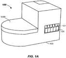
FIG. 1A illustrates an isometric view of an immunoassay apparatus according to embodiments. -
FIG. 1B illustrates an isometric view of an immunoassay apparatus with the housing removed according to embodiments. -
FIG. 2 illustrates a top plan schematic view of components of an immunoassay apparatus with the housing shown dotted according to embodiments. -
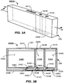
FIGs. 3A and 3B illustrate isometric and cross-sectioned side views, respectively, of a reagent dispenser apparatus according to embodiments. -
FIG. 3C illustrates a partial cross-sectioned side view of a dispense mechanism having a dispense port operable to open and close to dispense reagent from the reagent dispenser apparatus according to embodiments. -
FIG. 3D illustrates a partial cross-sectioned side view of an alternative dispense mechanism including a dispense port operable to open and close to dispense reagent from the reagent dispenser apparatus according to embodiments. -
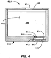
FIG. 4 illustrates a cross-sectioned side view of a single reagent dispenser apparatus adapted to dispense only a single reagent type according to embodiments. -
FIG. 5A illustrates a partial cross-sectioned side view of a reagent dispensing apparatus including a reagent dispenser apparatus according to embodiments. -
FIG. 5B illustrates a partial cross-sectioned side view of a reagent dispensing apparatus in the act of dispensing a reagent into a reaction vessel from a reagent dispenser apparatus according to embodiments. -
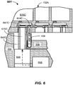
FIG. 6 illustrates an alternative embodiment of a reagent dispensing apparatus including pneumatic actuation of the reagent dispenser apparatus according to embodiments. -
FIG. 7 illustrates a top plan schematic view of components of an alternate immunoassay apparatus according to embodiments. -
FIG. 8 illustrates a flowchart of a dispensing method according to embodiments. - In existing immunoassay apparatus, it may be desired to provide multiple reagents within a particular immunoassay instrument such that a wide variety of tests may be carried out. Prior art systems have included multi-well reagent dispenser apparatus, such as the DIMENSION® ABS FLEX® reagent cartridges available from Siemens Healthcare Diagnostics Inc. Such wells of these multi-well reagent containers may be accessed through the top by one or more aspirating probes, which may pierce a thin film that may be adhered atop of the reagent dispenser container. Multiple probes may be used in current systems to prevent reagent carryover. Moreover, separate probes may be used to dispense sample fluid (e.g., blood or blood constituent). Furthermore, existing conventional systems may have multiple probe washing stations, water backing systems per probe, and even a robot per probe in order to accomplish the desired movements of the respective probes. Such systems are therefore relatively complex requiring multiple robots to move the numerous aspirating probes between the reagent container wells, sample containers, and the reaction vessels (e.g., cuvettes), as well as multiple probe washing stations and water backing systems.
- In view of the foregoing problems and complexities of conventional reagent dispenser systems, embodiments of the present invention provide reagent dispenser apparatus, reagent dispensing apparatus adapted to dispense reagent from the reagent dispenser apparatus, and dispensing methods adapted and operational to readily dispense reagent, but without requiring a dispensing probe. Accordingly, the reagent dispensing apparatus and immunoassay instrument including the reagent dispensing apparatus may be made much less complex by reducing the number of robots, number of wash stations, water backing lines and pumps, as well as the number of aspiration probes. The reagent dispensing apparatus in accordance with one or more embodiments may also reduce the overall time it takes to dispense reagent. In some embodiments, the relative size of the immunoassay instrument may be made smaller.
- In a first embodiment, an immunoassay apparatus is provided. The immunoassay apparatus includes a reaction vessel carrier (e.g., a cuvette-carrying ring) containing one or more reaction vessels, and a dispenser support containing one or more reagent dispenser container wherein at least some of the reagent dispense container, and preferably all, include a dispense mechanism. The dispense mechanism may include dispense port operable to open and close to dispense a reagent. The dispense port is operable to dispense reagent directly into the one or more of the reaction vessels contained in the reaction vessel carrier located below the dispenser support. In some embodiments, the dispense mechanism may be actuatable to dispense reagent. Mechanical and pneumatic dispensing actuation is described. The actuation may comprise one to several actuation cycles in order to dispense a predefined volume "shots" of the reagent.
- In another aspect, a reagent dispensing apparatus is provided having a dispenser support and one or more reagent dispenser containers provided in the dispenser support. At least one (and preferably all) of the reagent dispenser containers includes a dispense mechanism. The dispense mechanism includes a dispense port and is operable to open and close to dispense a reagent. The dispense mechanism may include a valve or other suitable structure operable to enable dispensing of reagent from, for example, a bottom of the reagent container body directly into the reaction vessel (e.g., cuvette).
- In another aspect, a reagent dispenser apparatus is provided, comprising a reagent container having a dispense mechanism. The dispense mechanism includes a dispense port operable to open and close to dispense reagent.
- These and other aspects and features of embodiments of the invention will be described with reference to
FIGs. 1-8 herein. - In accordance with one or more embodiments of the invention, as best shown in
FIGs. 1A ,1B , and2 , animmunoassay apparatus 100 containing an improvedreagent dispensing apparatus 101 and one or morereagent dispenser apparatus Reagent dispensing apparatus 101 may have a single well or multiple-wells, or combinations thereof, as shown. Thus, eachreagent dispenser apparatus Reagent dispenser apparatus immunoassay apparatus 100 is useful for carrying out immunoassay testing to determine the presence of a particular analyte or other material or substance of interest contained within a specimen (e.g., a sample of a biofluid). - In particular, the described embodiment includes a housing 103 (shown dotted in
FIG. 2 ) that may fully or partially surround the various internal components. Thereagent dispensing apparatus 101 may be received in thehousing 103, which may be made of plastic or other suitable rigid material. Thereagent dispensing apparatus 101 may be made up of at least adispenser support 104 and areaction vessel carrier 106, which is configured to contain one ormore reaction vessels 108. Thedispenser support 104, which may be in the form of a carousel, may have any suitable shape adapted to receive and position one ormore reagent dispensers reaction vessel carrier 106 may have any suitable shape adapted to support one or more reaction vessels underneath thedispenser support 104. - In particular, the
reagent dispensers dispenser support 104 in some embodiments. For example, thereagent dispensers dispenser support 104 from arotational axis 110 thereof. Suitable pockets or other retaining or locking features may be provided on thedispenser support 104 to position and secure thereagent dispensers dispenser support 104 may be rotatable about therotational axis 110 by a suitable dispenser support motor 112 (shown dotted) in some embodiments.Dispenser support motor 112 may be a stepper motor or the like and may receive control signals from acontroller 111. Other suitable motors and/or drive systems may be used to accomplish rotation and/or positioning of thedispenser support 104. For example, in some embodiments, thedispenser support motor 112 may directly drive a shaft coupled to or integral with thedispenser support 104 and may have a rotational shaft located in line with therotational axis 110. In other embodiments, the motor may be offset from therotational axis 110 and drive thedispenser support 104 via a suitable drive system, such as a gear, pulley and belt, chain, worm gear, combination, or the like. Any suitable means for causing movement (e.g., rotation) of thedispenser support 104 may be used. - The
dispenser support 104 includes a dispenser support body, which may be a molded body, having one or morereagent dispenser apparatus dispenser support 104 may have mounted therein, a plurality ofreagent dispenser apparatus reagent dispenser apparatus port 314A (SeeFIG. 3B ). The dispenseport 314A may include any suitable functionality (e.g., one or more valves) that is operable to open and close the dispense port, i.e., control flow there through, to dispense areagent 316A directly into the one or more of thereaction vessels 108. Thereaction vessels 108 may be located in thereaction vessel carrier 106, wherein at least a portion of thereaction vessel carrier 106 may lie below thedispenser support 104. In the depicted embodiment, thereaction vessel carrier 106 is provided as a carrier ring configured to rotate underneath a portion of thedispenser support 104. When dispensing takes place, aparticular reaction vessel 108 to receive reagent is positioned directly below particular dispenseport 314A of areagent dispenser apparatus 102A. Thus, dispensing occurs without any pipetting operation with a probe, as was the case in conventional immunoassay instruments. - As shown in
FIG. 2 , the footprint of thedispenser support 104 at least partially overlaps thereaction vessel carrier 106 such that dispensing ofreagent 316A may be accomplished directly into areaction vessel 108. Accordingly, the operation of dispensing areagent 316A is substantially improved. In particular, a number of aspiration probes provided in theimmunoassay apparatus 100 may be reduced, a number of probe wash stations may be reduced, water backing systems may be reduced, and dispensing speed may possibly be increased. - In one or more embodiments, the
reaction vessel carrier 106 may comprise a carrier ring having a plurality of receptacles (e.g., pockets or the like) configured to receivereaction vessels 108 and rotate them underneath a portion of thedispenser support 104.Reaction vessel carrier 106 comprising a carrier ring may hold the reaction vessels 108 (e.g., clear cuvettes) and provide them in a circle-shaped orientation arranged at a common radius. More than one radius may be provided in some embodiments, wherein a first plurality of reaction vessels may be provided at a first radius, and a second plurality of reaction vessels may be provided at a different radius.Reaction vessel carrier 106 may include any suitable construction enabling the carrying ofreaction vessels 108, and may include a plurality of suitable receptacles adapted to receivereaction vessels 108 therein. Likedispenser support 104,reaction vessel carrier 106 may be rotated incrementally by a suitable rotational member, such as carrier motor 114 (shown dotted inFIG. 2 ).Carrier motor 114 may be a stepper motor or other motor as described for thedispenser support 104. Rotation of thereaction vessel carrier 106 may be controlled via control signals from thecontroller 111. - Again referring to
FIGs. 1B , and2 , theimmunoassay apparatus 100 includes aspecimen staging area 118. Specimens contained in specimen containers 119 (e.g., sample tubes or blood collection vessels) may be provided to thespecimen staging area 118 in one or more sample racks 120. In the depicted example, thesample rack 120 is a 15 x 5 position rack enabling the processing of 75 specimens. Other sizes ofsample racks 120 may be used. One or more than one sample rack may be provided at thespecimen staging area 118. The one ormore sample racks 120 may be inserted into and/or removed from theimmunoassay apparatus 100 through anopening 121 formed in thehousing 103. Opening 121 may include an opening, removable or openable door in some embodiments. Locating features (not shown) within theimmunoassay apparatus 100 may function to precisely position the one ormore sample racks 120 within the interior of theimmunoassay apparatus 100, and may secure it to a portion of thehousing 103 or an internal frame of theimmunoassay apparatus 100, for example. - A
sample probe 107 may also be provided within theimmunoassay apparatus 100. Thesample probe 107 may include aproboscis portion 107P and abody 107B. Thebody 107B may be connected to a pump or other source of vacuum pressure (not shown) such that specimen aspiration may take place. Suitable configurations of aspiration systems which may be used with embodiments of the present invention are described inUS Pat. Nos. 7, 867, 769 ;7, 634, 378 ;7, 477, 997 ;7,186,378 ;7,150,190 ; and6,370,942 , for example. Other suitable aspiration systems may be used. - The
body 107B may be coupled to, and moved by, asuitable robot 122, which may be coupled to thehousing 103 either directly, or through an internal frame. Therobot 122 may be any suitable robot adapted to move thesample probe 107 from thespecimen containers 119 at thespecimen staging area 118 to thereaction vessel 108 resident in thereaction vessel carrier 106. Therobot 122 may be a multi-arm robot, a gantry robot, or the like. Other types of robots may be used. Therobot 122 may include suitable elements to accomplish three-dimensional motion of theproboscis portion 107P of thesample probe 107. For example, therobot 122 may be capable of motion in the X, Y and Z directions as shown. The means for moving thesample probe 107 may include any suitable conventional motion-producing mechanism, such as one or more stepper motors, servo motors, pneumatic or hydraulic motors, electric motors, or the like. Furthermore, drive systems including chains, guides, pulleys and belt arrangements, gear or worm drives or other conventional drive components may be utilized to cause the motion of thesample probe 107. - Adjacent to the
specimen staging area 118, may be one or moreprobe tip supply 125 that includes probe tips that may be picked up by theproboscis portion 107P.Immunoassay apparatus 100 may include areaction vessel supply 126, which may be a cuvette loader, for example.Reaction vessel supply 126 may be a conventional cuvette loader and is operational to loadreaction vessels 108 into thereaction vessel carrier 106. - The
immunoassay apparatus 100 also includes atest component 115, that may determine an analyte, substance, or characteristic, or the like of the reaction fluid contained in thereaction vessel 108, such as after undergoing a reaction. For example, in some embodiments,test component 115 may be an apparatus (e.g., a luminometer) that operates to measure luminescence of the reaction sample through a reaction vessel 108 (e.g., a clear cuvette). In some embodiments, the testing is carried out while thereaction vessel 108 is resident inreaction vessel carrier 106. In other embodiments, an elevator may be used to lift or remove thereaction vessel 108 from thereaction vessel carrier 106 during the test. In some embodiments, thetest component 115 may send a light signal and determine therefrom (e.g., via a sensor) another characteristic of the reaction fluid (containing specimen, one or more reagents, and possibly a dilutant). For example, thetest component 115 may determine luminescence, absorbance, or the like of the reaction fluid contained in thereaction vessel 108. Other types of testing may be carried out on the reaction liquid in thereaction vessel 108. For example, photometric, turbidimetric, chemiluminescence, nephelometric, or other testing may be carried out. More than onetest component 115 may be provided. Thetest component 115 may be tested after undergoing a suitable incubation period and wash process atwash station 127 while resident inreaction vessel carrier 106. The reaction process carried out in thereaction vessel 108 and wash process carried out inwash station 127 are entirely conventional. - The
immunoassay apparatus 100 may also include anidentification reader 129, such as a barcode reader, or any suitable identification code, indicia, device, or the like. Theidentification reader 129 may be provided at any suitable position to enable identification of, for example, thesample rack 120 that has been inserted into theimmunoassay apparatus 100. Identification of, and location of theindividual specimen containers 119 in thesample rack 120 may be known based upon stored data that is contained in, or assessable by, thecontroller 111. Theidentification reader 129 may also read codes (e.g., barcodes, indicia or other identification devices) located on one or more (preferably all) of thereagent dispenser apparatus dispenser support 104. This allows the type of reagent contained therein, and possibly other information about thereagent dispenser apparatus dispenser support 104 is first mounted in theimmunoassay apparatus 100, thedispenser support 104 may be rotated so that eachreagent dispenser apparatus identification reader 129 so that the identity, location, and/or content of thereagent dispenser apparatus controller 111. As the reagent in thereagent dispenser apparatus dispenser support 104 may be removed, refilled, and then replaced in theimmunoassay apparatus 100. Adoor 103D above thedispenser support 104, which may be removable or hinged, may be provided. - An embodiment of a
reagent dispenser apparatus 102A in accordance with another aspect of the invention will now be described with reference toFIGs. 3A-3C .Reagent dispenser apparatus 102A includes a reagent container formed by acontainer body 339 with one or more reagent storage chambers (e.g., 340A, 340B, and 340C) formed by external and internal walls therein. Each reagent storage chamber (e.g., 340A, 340B, and 340C) may contain a different type of reagent. A reagent is a substance used in a chemical reaction to detect, measure, examine, or produce another substance(s). The reagent may be a chemiluminescence reagent (e.g., chemiluminescence phases such as solid, lite, and buffer solutions), a mitigation agent (such as NaCOI), or the like. A diluting agent (e.g., water) may also be dispensed as part of a chemical or biological reaction in areaction vessel 108 along with the reagent. Reagents, as used herein, are dispensed materials that are used in an immunoassay reaction. The number of agent storage chambers may be one (e.g.,FIG. 4 ) or more than one (such as three shown inFIGs. 3A-3B ). Other numbers of reagent storage chambers may be used. - The
reagent dispenser apparatus 102A further includes a dispense mechanism. The dispense mechanism may include a dispense port (e.g., 314A, 314B, 314C) associated with some or all of the reagent storage chambers (e.g., 340A, 340B, and 340C). Dispense ports (e.g., 314A, 314B, 314C) are operable to open and close to dispense reagent (e.g., reagent 316A, 316B, 316C) from the respective reagent storage chambers (e.g., 340A, 340B, and 340C). "Open" as used herein refers to a condition where flow through a particular dispense port (e.g., 314A, 314B, 314C) is allowed, whereas "close" as used herein refers to a condition where flow through the dispense port (e.g., 314A, 314B, 314C) is not allowed. For a single reagent dispense operation, the dispenseport 314A may be opened once and closed once, for example. Once opened, a defined amount (e.g., volume) ofreagent 316A may be dispensed. This is otherwise referred to herein as a "shot" of reagent. Defined amounts (e.g., shots) ofreagents ports reaction vessel 108. - In the depicted embodiment, the dispense mechanism includes one or more reagent dispense chambers (e.g., 342A, 342B, 342C). Reagent dispense chambers (e.g., 342A, 342B, 342C) are shown coupled (e.g., fluidly connected) to the respective reagent storage chambers (e.g., 340A, 340B, and 340C) by one or more inlet ports (e.g.,
inlet ports Inlet ports reagent reagent storage chambers chambers chambers Reagent storage chambers - Dispense
ports valve valve reagent chambers valve chambers valve valve valve valve valve bottom surface 339B of thecontainer body 339. In particular, the dispenseports bottom surface 339B) of thecontainer body 339 in some embodiments. - In the depicted embodiment, an
inlet valve inlet ports Inlet valve inlet ports reagent storage chambers chambers Inlet valve valve container body 339 has the plurality of dispenseports ports reaction vessels 108 that are mounted in thereaction vessel carrier 106 by appropriate motions (e.g., rotations) of thedispenser support 104 and thereaction vessel carrier 106. - For example, in the depicted embodiment, rotation of the
dispenser support 104 and thereaction vessel carrier 106 may be coordinated to vertically align dispenseport 314C with a desiredreaction cuvette 108 that is to receive thereagent 316C. Likewise, dispenseport 314B may be aligned with a desiredreaction cuvette 108 that is to receive thereagent 316B, and dispenseport 314A may be aligned with a desiredreaction cuvette 108 that is to receive thereagent 316A. Through appropriate coordinated rotations of thedispenser support 104 andreaction vessel carrier 106, any onereaction cuvette 108 may then receive one, more than one, or even more than two reagents. Reagent may be received from a single reagent dispenser apparatus adapted to contain an auxiliary reagent (e.g.,reagent dispenser apparatus 102B) or from a multiple reagent dispenser apparatus (e.g.,reagent dispenser apparatus 102A). - In operation, the depicted embodiment of
dispenser apparatus 102A, as shown inFIG. 3C , includes the reagent dispensechamber 342A having aninlet port 344A and dispenseport 314A. The dispense mechanism includes aninlet valve 346A (e.g., a one-way valve) controlling flow through theinlet port 344A, and a dispensevalve 345A (e.g., a one-way valve) controlling flow through the dispenseport 314A. The reagent dispensechamber 342A may include amoveable wall 347A adapted to change a volume of the reagent dispensechamber 342A. Themoveable wall 347A may comprise a flexible diaphragm, bellows, or other flexible member. -
Moveable wall 347A may be made of any suitable flexible material, such as a polymer (e.g., rubber, silicone, or the like) . Moveable wall 347 may be molded or bonded to aclosure member 348A, which may have the dispenseport 314A and dispensevalve 345A formed or received thereon. Actuation of themoveable wall 347A, such as by anactuation member 350A (shown dotted), causes movement of themoveable wall 347A. Upward movement of theactuation member 350A displacesreagent 316A from the reagent dispensechamber 342A, as shown by first dottedarrows 352, into areaction vessel 108 positioned in thereaction vessel carrier 106 directly vertically below the dispenseport 314A.Actuation member 350A may be a rod or other suitable displaceable member coupled to an actuator, such as a solenoid, piezoactuator, or the like. Actuation of theactuation member 350A through a predefined translational distance (e.g., stroke) in the upward direction flexes and displaces themoveable wall 347A and thereby displaces a known amount ofreagent 316A (i.e., a "shot" ofreagent 316A) from the reagent dispensechamber 342A into thereaction vessel 108, as shown by first dottedarrows 352. - Retraction motion of the
actuation member 350A downward through a defined return distance draws in another "shot" of thereagent 316A into the reagent dispensechamber 342A from thereagent storage chamber 340A throughinlet port 344A andinlet valve 346A as shown by second dottedarrows 354. Actuation of theactuation member 350A may be carried out once to dispense a single "shot" or multiple times to dispense multiple "shots" of thereagent 316A into aparticular reaction vessel 108 that has been vertically aligned with the dispenseport 314A through appropriate coordinated rotations of thedispenser support 104 andreaction vessel carrier 106. -
FIG. 3D illustrates another embodiment of areagent dispenser apparatus 302 that includes reagent dispensechamber 342A having aninlet port 344A and dispenseport 314A. The dispense mechanism includes aninlet valve 346A (e.g., a one-way valve) controlling flow through theinlet port 344A, and a dispensevalve 345A (e.g., a one-way valve) controlling flow through the dispenseport 314A. The reagent dispensechamber 342A includes amoveable wall 347B adapted to change a volume of the reagent dispensechamber 342A. Themoveable wall 347B in this embodiment may comprise a puck that is sealed to aclosure member 348B, by a suitable sealing member 349 (e.g., O-ring, lip seal or other suitable sealing member). Upward motion of theactuation member 350A causes movement of themoveable wall 347B and displacesreagent 316A from reagent dispensechamber 342A.Spring 350 returns the moveable wall upon retraction of theactuation member 350A and draws in a new shot ofreagent 316A from thereagent storage chamber 340A. -
FIG. 4 illustrates an embodiment of a single-reagent dispenser apparatus 402 that includes reagent dispensechamber 442 having aninlet port 444 and dispenseport 414. The dispense mechanism includes an inlet valve 446 (e.g., a one-way valve) allowing flow into theinlet port 444 when sufficient pressure differential across the valve is present, but not allowing backflow, and a dispense valve 445 (e.g., a one-way valve) controlling flow out of the dispenseport 414 once sufficient pressure is reached. The reagent dispensechamber 442 includes amoveable wall 447 adapted to change a volume of the reagent dispensechamber 442. Themoveable wall 447 in this embodiment may comprise any of the previously-disclosed structures. Upward motion of an actuation member (not shown) contacts themoveable wall 447 and displacesreagent 416 from reagent dispensechamber 442. Upon retraction of the actuation member, a new shot ofreagent 416 from thereagent storage chamber 440 is drawn into the reagent dispensechamber 442 so that it is now ready for another shot dispense. - In the depicted embodiment, a top of the
container body 439 may include atop opening 441 adapted to receive a probe therein, should thereagent dispenser apparatus 402 be used in a conventional, probe-aspirated system. Thus, as configured, thereagent dispenser apparatus 402 is capable of either top probe aspiration or bottom probe-less aspiration. However, it should be understood that in a reagent dispensing apparatus as described herein, thetop opening 441 may not be present. In the case where thetop opening 441 is present to allow use in conventional, probe-aspirated systems, thetop opening 441 may be covered with asealing sheet 451, such as with an adhesive-backed foil. Likewise,such openings 341A-341C may also be present in the multi-chamber configurations, as shown inFIG. 3A and 3B to allow use in either conventional, probe-aspirated systems, or the inventive bottom-aspirated systems as described herein. Likewise,dispenser apparatus 102A may include asealing sheet 351 covering and sealing theopenings 341A-341C. Sealing sheet is not shown inFIG. 3A , for clarity. -
FIGs. 5A-5B illustrates a partial cross-sectioned side view of areagent dispensing apparatus 501 including areagent dispenser apparatus 102A according to embodiments.Reagent dispensing apparatus 501 may be included in animmunoassay apparatus 100 as described herein. As shown, thereagent dispensing apparatus 501 includes a dispenser support 104 (a portion shown), and one or morereagent dispenser apparatus 102A provided in thedispenser support 104. Thereagent dispensing apparatus 102A may be provided in thedispenser support 104 by being registered on one or more features, such as lips, recesses, posts, or the like. Locking features may be provided, such as snap-fit locking tabs or other suitable locking structure that secures thereagent dispenser apparatus 102A to thedispenser support 104. Thereagent dispenser apparatus 102A includes a dispenseport 314C, as shown, operable to open and close to dispense a reagent 316. The dispenseport 314C remains closed (no flow) when the pressure in the reagent dispensechamber 342C is below a predesigned threshold pressure, and the dispenseport 314C is opened (flowing) when the pressure in the reagent dispensechamber 342C is above predesigned threshold pressure. As shown, thedispenser support 104 with the attached one or morereagent dispenser apparatus 102A, is removable from thehousing 103. Thedispenser support 104 may include ahub 104H that receives a lockingmember 552 therein. Lockingmember 552 may be contacted by a fastening member 554 (e.g., a threaded knob) to secure thedispenser support 104 to ashaft 112S of thedispenser support motor 112. A rotation registering feature 555 (e.g., a pin or other feature) may be used to allow thedispenser support 104 to be mounted on theshaft 112S in only one rotational orientation.Rotation registering feature 555 may be a pin mounted in a shoulder of theshaft 112S. Other suitable rotation registry features may be used. - To dispense
reagent 316C, thereaction vessel carrier 106 containing areaction vessel 108 is rotated bycarrier motor 114 and thedispenser support 104 is rotated bydispenser support motor 112 to appropriate rotational orientations to vertically align thereaction vessel 108 below the dispenseport 314C. Theactuation member 350A may then be actuated byactuator 556 to move themoveable wall 347C as shown inFIG. 5B , which dispenses a predetermined volume (e.g., a shot) of thereagent 316C directly into thereaction vessel 108. A respective actuator and actuator member (e.g., 350A, 350B, and 350C) may be provided at different position to accomplish the dispensing for eachreagent reagent dispenser apparatus 102A. -
FIG. 6 illustrates a partial cross-sectioned side view of another alternative embodiment of areagent dispensing apparatus 601 including areagent dispenser apparatus 102A according to embodiments. The depictedreagent dispensing apparatus 601 includes pneumatic actuation of themoveable wall 647C. Theactuator 656 moves theactuation member 650C into sealed contact with themoveable wall 647C, which may be an elastomer bladder or the like. Once extended into sealed contact, apneumatic source 658, such as an air pump, may be operated to provide a predetermined gas pressure in apassage 670C in theactuation member 650C, which flexes the moveable wall 747C and causes a shot of thereagent 316C to be dispensed into thereaction vessel 108 located below the dispenseport 614C. Pneumatic and mechanical actuation apparatus have been described herein. However, any suitable actuation technique that causes reagent to be dispensed from thereagent storage 616C into thereaction vessel 108 without a pipetting operation may be used. -
FIG. 7 illustrates another embodiment ofimmunoassay apparatus 700. In this embodiment, adispenser support 704 of thereagent dispensing apparatus 701 having one ormore dispenser apparatus dispenser support 704 may move along a non-rotary path (e.g., linearly along a linear path) on one or more path restraints, such asguide rails dispenser support 704 overlaps thereaction vessel carrier 706 such that an agent (e.g., a reagent) may be dispensed directly into areaction vessel 108 mounted in thereaction vessel carrier 706 below thedispenser support 704. Non-rotary motion may be produced by anactuator 774 coupled between the housing 703 (or to a frame member with the housing 703) and thedispenser support 704. Anysuitable actuator 774 may be used, such as a linear variable displacement transducer (LVDT) or the like. The other components of theimmunoassay apparatus 700 may be as discussed above. Thus, in this embodiment, one or more agents (e.g., reagent) may be dispensed directly into areaction vessel 108 from a dispense port (e.g., outlet) without a pipetting operation. As shown, linear actuation of thedispenser support 704 coupled with coordinated rotation of thereaction vessel carrier 706 can align any desired dispense port of any desiredreagent dispenser apparatus reaction vessel 108. - An embodiment of a method of dispensing a reagent (e.g., 316A, 316B, 316C, 414, 614C) into a reaction vessel (e.g., reaction vessel 108) will now be described with reference to
FIG. 8 . Themethod 800 includes, in 802, providing a reagent dispenser apparatus (e.g.,reagent dispenser apparatus port - The
method 800 includes, in 804, dispensing the reagent from the reagent dispenser apparatus without a pipetting operation. In particular, the reagent is dispensed directly from the reagent dispenser apparatus into the reaction vessel through a dispense port. Reagent may flow from a reagent storage chamber to a reagent dispense chamber and then into the reaction vessel from the dispense port in some embodiments. - While the invention is susceptible to various modifications and alternative forms, specific system and apparatus embodiments and methods thereof have been shown by way of example in the drawings and are described in detail herein. It should be understood, however, that it is not intended to limit the invention to the particular systems, apparatus, or methods disclosed but, to the contrary, the intention is to cover all modifications, equivalents, and alternatives falling within the scope of the invention.
Claims (10)
- An immunoassay apparatus, comprising:a reaction vessel carrier containing one or more reaction vessel(s); anda dispenser support containing one or more reagent dispenser apparatus having one or more reagent container(s), said reagent container(s) comprising (i) a reagent storage chamber and (ii) a reagent dispense chamber having a dispense port coupled to the reagent dispense chamber,characterized in that said dispense port is operable to open and close to dispense a reagent directly into the one or more reaction vessel(s) located below the dispenser support andin that the dispense chamber has a vertically moveable wall adapted to change a volume of the reagent dispensing chamber by vertical movement of the vertically moveably wall and thereby displacing a known amount of the reagent from the reagent dispense chamber into the reaction vessel.
- The immunoassay apparatus of claim 1, further comprising a dispense valve adapted and operable to control reagent flow through the dispense port.
- The immunoassay apparatus of claim 1, further comprising an inlet port connecting the reagent storage chamber and the reagent dispense chamber, and a one-way valve operative with the inlet port.
- The immunoassay apparatus of claim 1, wherein the dispense port exits from a bottom of the reagent container.
- The immunoassay apparatus of claim 1, comprising a container body having a plurality of dispense ports spaced along a length of the container body.
- The immunoassay apparatus of claim 1, wherein the moveable wall comprises a flexible diaphragm.
- The immunoassay apparatus of claim 1, wherein the reaction vessel carrier comprises a carrier ring configured to rotate underneath a portion of the dispenser support.
- The immunoassay apparatus of claim 1, comprising an actuation member adapted to engage the one or more reagent dispenser apparatus to cause dispense of the reagent directly into the one or more of the reaction vessel.
- A method of dispensing a reagent, comprising:providing an immunoassay apparatus according to any one or more of claims 1 to 8; anddispensing the reagent from the reagent dispenser apparatus without a pipetting operation.
- The method of claim 9, comprising:
moving a moveable wall of the reagent dispenser apparatus to accomplish the dispensing of the reagent from the dispensing port.
Applications Claiming Priority (4)
| Application Number | Priority Date | Filing Date | Title |
|---|---|---|---|
| US201361858230P | 2013-07-25 | 2013-07-25 | |
| US201361881069P | 2013-09-23 | 2013-09-23 | |
| EP14829124.8A EP3024583A4 (en) | 2013-07-25 | 2014-07-22 | REAGENT DISPENSERS, DISTRIBUTION APPARATUS, AND CORRESPONDING METHODS |
| PCT/US2014/047568 WO2015013253A2 (en) | 2013-07-25 | 2014-07-22 | Reagent dispensers, dispensing apparatus, and methods |
Related Parent Applications (2)
| Application Number | Title | Priority Date | Filing Date |
|---|---|---|---|
| EP14829124.8A Division EP3024583A4 (en) | 2013-07-25 | 2014-07-22 | REAGENT DISPENSERS, DISTRIBUTION APPARATUS, AND CORRESPONDING METHODS |
| PCT/US2014/047568 Previously-Filed-Application WO2015013253A2 (en) | 2013-07-25 | 2014-07-22 | Reagent dispensers, dispensing apparatus, and methods |
Publications (2)
| Publication Number | Publication Date |
|---|---|
| EP3747545A1 true EP3747545A1 (en) | 2020-12-09 |
| EP3747545B1 EP3747545B1 (en) | 2024-09-18 |
Family
ID=52393954
Family Applications (2)
| Application Number | Title | Priority Date | Filing Date |
|---|---|---|---|
| EP19151130.2A Active EP3747545B1 (en) | 2013-07-25 | 2014-07-22 | Reagent dispensers, dispensing apparatus, and methods |
| EP14829124.8A Withdrawn EP3024583A4 (en) | 2013-07-25 | 2014-07-22 | REAGENT DISPENSERS, DISTRIBUTION APPARATUS, AND CORRESPONDING METHODS |
Family Applications After (1)
| Application Number | Title | Priority Date | Filing Date |
|---|---|---|---|
| EP14829124.8A Withdrawn EP3024583A4 (en) | 2013-07-25 | 2014-07-22 | REAGENT DISPENSERS, DISTRIBUTION APPARATUS, AND CORRESPONDING METHODS |
Country Status (3)
| Country | Link |
|---|---|
| US (1) | US10010885B2 (en) |
| EP (2) | EP3747545B1 (en) |
| WO (1) | WO2015013253A2 (en) |
Families Citing this family (5)
| Publication number | Priority date | Publication date | Assignee | Title |
|---|---|---|---|---|
| WO2016130962A1 (en) | 2015-02-13 | 2016-08-18 | Abbott Laboratories | Automated storage modules for diagnostic analyzer liquids and related systems and methods |
| US11021378B2 (en) * | 2015-03-13 | 2021-06-01 | The Cleveland Clinic Foundation | Sterile and/or purified fluid and/or solution delivery system |
| US10725059B2 (en) * | 2015-04-06 | 2020-07-28 | Meso Scale Technologies, Llc. | High throughput system for performing assays using electrochemiluminescence including a consumable shaking apparatus |
| EP3548901B1 (en) | 2016-12-02 | 2024-01-31 | Gen-Probe Incorporated | Laboratory automated instruments, systems, and methods for transporting sample receptacle carriers |
| WO2023188795A1 (en) * | 2022-03-28 | 2023-10-05 | 株式会社日立ハイテク | Automatic analysis device |
Citations (11)
| Publication number | Priority date | Publication date | Assignee | Title |
|---|---|---|---|---|
| US4146156A (en) * | 1976-02-03 | 1979-03-27 | Steiner American Corporation | Soap dispensing system |
| US6193933B1 (en) * | 1997-10-27 | 2001-02-27 | Hitachi, Ltd. | Automatic analysis apparatus |
| US6370942B1 (en) | 2000-05-15 | 2002-04-16 | Dade Behring Inc. | Method for verifying the integrity of a fluid transfer |
| US20040197230A1 (en) * | 2002-01-30 | 2004-10-07 | Ventana Medical Systems, Inc. | Method and apparatus for modifying pressure within a fluid dispenser |
| US7150190B2 (en) | 2005-03-21 | 2006-12-19 | Dade Behring Inc. | Method and apparatus for capacitively determining the uppermost level of a liquid in a container |
| US7186378B2 (en) | 2003-07-18 | 2007-03-06 | Dade Behring Inc. | Liquid sampling probe and cleaning fluidics system |
| US20070272710A1 (en) * | 2006-05-25 | 2007-11-29 | Sakura Finetek, U.S.A., Inc. | Fluid dispensing apparatus |
| US7477997B2 (en) | 2005-12-19 | 2009-01-13 | Siemens Healthcare Diagnostics Inc. | Method for ascertaining interferants in small liquid samples in an automated clinical analyzer |
| US7634378B2 (en) | 2007-11-30 | 2009-12-15 | Siemens Healthcare Diagnostics Inc. | Detection of insufficient sample during aspiration with a pipette |
| US7867769B2 (en) | 2007-09-19 | 2011-01-11 | Siemens Healthcare Diagnostics Inc. | Clog detection in a clinical sampling pipette |
| US20120193376A1 (en) * | 2011-02-01 | 2012-08-02 | Sakura Finetek U.S.A., Inc. | Fluid dispensing system |
Family Cites Families (9)
| Publication number | Priority date | Publication date | Assignee | Title |
|---|---|---|---|---|
| US4862932A (en) | 1988-04-20 | 1989-09-05 | Bio-Rad Laboratories, Inc. | Fraction collector |
| US5947167A (en) * | 1992-05-11 | 1999-09-07 | Cytologix Corporation | Dispensing assembly with interchangeable cartridge pumps |
| US6092695A (en) * | 1992-05-11 | 2000-07-25 | Cytologix Corporation | Interchangeable liquid dispensing cartridge pump |
| US6093574A (en) * | 1997-08-11 | 2000-07-25 | Ventana Medical Systems | Method and apparatus for rinsing a microscope slide |
| US20050135972A1 (en) * | 1997-08-11 | 2005-06-23 | Ventana Medical Systems, Inc. | Method and apparatus for modifying pressure within a fluid dispenser |
| EP1631388A4 (en) | 2003-06-09 | 2007-09-05 | Dako Denmark As | Diaphram metering chamber dispensing systems |
| US7501283B2 (en) * | 2003-08-11 | 2009-03-10 | Sakura Finetek U.S.A., Inc. | Fluid dispensing apparatus |
| US20080006333A1 (en) * | 2006-06-27 | 2008-01-10 | Exxonmobil Research And Engineering Company | Structure of a fuel tank for a multi-fuel system |
| WO2012128603A1 (en) * | 2011-03-22 | 2012-09-27 | Aouad Salah Mohammed | Automatic device and process for preparing solutions |
-
2014
- 2014-07-22 EP EP19151130.2A patent/EP3747545B1/en active Active
- 2014-07-22 EP EP14829124.8A patent/EP3024583A4/en not_active Withdrawn
- 2014-07-22 US US14/905,631 patent/US10010885B2/en active Active
- 2014-07-22 WO PCT/US2014/047568 patent/WO2015013253A2/en not_active Ceased
Patent Citations (11)
| Publication number | Priority date | Publication date | Assignee | Title |
|---|---|---|---|---|
| US4146156A (en) * | 1976-02-03 | 1979-03-27 | Steiner American Corporation | Soap dispensing system |
| US6193933B1 (en) * | 1997-10-27 | 2001-02-27 | Hitachi, Ltd. | Automatic analysis apparatus |
| US6370942B1 (en) | 2000-05-15 | 2002-04-16 | Dade Behring Inc. | Method for verifying the integrity of a fluid transfer |
| US20040197230A1 (en) * | 2002-01-30 | 2004-10-07 | Ventana Medical Systems, Inc. | Method and apparatus for modifying pressure within a fluid dispenser |
| US7186378B2 (en) | 2003-07-18 | 2007-03-06 | Dade Behring Inc. | Liquid sampling probe and cleaning fluidics system |
| US7150190B2 (en) | 2005-03-21 | 2006-12-19 | Dade Behring Inc. | Method and apparatus for capacitively determining the uppermost level of a liquid in a container |
| US7477997B2 (en) | 2005-12-19 | 2009-01-13 | Siemens Healthcare Diagnostics Inc. | Method for ascertaining interferants in small liquid samples in an automated clinical analyzer |
| US20070272710A1 (en) * | 2006-05-25 | 2007-11-29 | Sakura Finetek, U.S.A., Inc. | Fluid dispensing apparatus |
| US7867769B2 (en) | 2007-09-19 | 2011-01-11 | Siemens Healthcare Diagnostics Inc. | Clog detection in a clinical sampling pipette |
| US7634378B2 (en) | 2007-11-30 | 2009-12-15 | Siemens Healthcare Diagnostics Inc. | Detection of insufficient sample during aspiration with a pipette |
| US20120193376A1 (en) * | 2011-02-01 | 2012-08-02 | Sakura Finetek U.S.A., Inc. | Fluid dispensing system |
Also Published As
| Publication number | Publication date |
|---|---|
| EP3024583A4 (en) | 2016-11-23 |
| US10010885B2 (en) | 2018-07-03 |
| EP3024583A2 (en) | 2016-06-01 |
| WO2015013253A2 (en) | 2015-01-29 |
| EP3747545B1 (en) | 2024-09-18 |
| WO2015013253A3 (en) | 2015-06-18 |
| US20160144364A1 (en) | 2016-05-26 |
Similar Documents
| Publication | Publication Date | Title |
|---|---|---|
| EP3747545B1 (en) | Reagent dispensers, dispensing apparatus, and methods | |
| US8187558B2 (en) | Containers for reducing or eliminating foaming | |
| US6375898B1 (en) | Analysis system | |
| US7855084B2 (en) | Chemistry system for clinical analyzer | |
| US4456037A (en) | Process of delivering samples and reagents | |
| US4311667A (en) | Delivering apparatus | |
| US10613106B2 (en) | Reaction vessel handling apparatus, testing apparatus, and methods using same | |
| US12405286B2 (en) | Pipetting device and method for the transfer of fluids | |
| US7998751B2 (en) | Method and apparatus for aspirating and dispensing small liquid samples in an automated clinical analyzer | |
| EP3444033B1 (en) | Cartridge for chemical or biological assays | |
| WO2008007598A1 (en) | Automatic analyzer | |
| US9545648B2 (en) | Magnetic particle washing apparatus and method | |
| US20040042339A1 (en) | Method and apparatus for mixing liquid samples using a sinusoidal mixing action | |
| MXPA06000036A (en) | Method for increasing capacity in an automatic clinical analyzer by using modular reagent delivery means. | |
| JPH04115136A (en) | Particle measuring apparatus | |
| TWI457561B (en) | Liquid testing system and liquid testing method | |
| US7569189B2 (en) | Opening and closing a container | |
| US20240102899A1 (en) | Sample purification device | |
| WO2006132324A1 (en) | Reaction container and reaction apparatus employing the same | |
| CN121995073A (en) | Sample analyzer | |
| JPWO2017163567A1 (en) | Solution discharge apparatus and solution discharge control method |
Legal Events
| Date | Code | Title | Description |
|---|---|---|---|
| STAA | Information on the status of an ep patent application or granted ep patent |
Free format text: STATUS: UNKNOWN |
|
| PUAI | Public reference made under article 153(3) epc to a published international application that has entered the european phase |
Free format text: ORIGINAL CODE: 0009012 |
|
| STAA | Information on the status of an ep patent application or granted ep patent |
Free format text: STATUS: THE APPLICATION HAS BEEN PUBLISHED |
|
| AC | Divisional application: reference to earlier application |
Ref document number: 3024583 Country of ref document: EP Kind code of ref document: P |
|
| AK | Designated contracting states |
Kind code of ref document: A1 Designated state(s): AL AT BE BG CH CY CZ DE DK EE ES FI FR GB GR HR HU IE IS IT LI LT LU LV MC MK MT NL NO PL PT RO RS SE SI SK SM TR |
|
| STAA | Information on the status of an ep patent application or granted ep patent |
Free format text: STATUS: REQUEST FOR EXAMINATION WAS MADE |
|
| 17P | Request for examination filed |
Effective date: 20210608 |
|
| RBV | Designated contracting states (corrected) |
Designated state(s): AL AT BE BG CH CY CZ DE DK EE ES FI FR GB GR HR HU IE IS IT LI LT LU LV MC MK MT NL NO PL PT RO RS SE SI SK SM TR |
|
| GRAP | Despatch of communication of intention to grant a patent |
Free format text: ORIGINAL CODE: EPIDOSNIGR1 |
|
| STAA | Information on the status of an ep patent application or granted ep patent |
Free format text: STATUS: GRANT OF PATENT IS INTENDED |
|
| INTG | Intention to grant announced |
Effective date: 20240409 |
|
| P01 | Opt-out of the competence of the unified patent court (upc) registered |
Effective date: 20240523 |
|
| GRAS | Grant fee paid |
Free format text: ORIGINAL CODE: EPIDOSNIGR3 |
|
| GRAA | (expected) grant |
Free format text: ORIGINAL CODE: 0009210 |
|
| STAA | Information on the status of an ep patent application or granted ep patent |
Free format text: STATUS: THE PATENT HAS BEEN GRANTED |
|
| AC | Divisional application: reference to earlier application |
Ref document number: 3024583 Country of ref document: EP Kind code of ref document: P |
|
| AK | Designated contracting states |
Kind code of ref document: B1 Designated state(s): AL AT BE BG CH CY CZ DE DK EE ES FI FR GB GR HR HU IE IS IT LI LT LU LV MC MK MT NL NO PL PT RO RS SE SI SK SM TR |
|
| REG | Reference to a national code |
Ref country code: GB Ref legal event code: FG4D |
|
| REG | Reference to a national code |
Ref country code: CH Ref legal event code: EP |
|
| REG | Reference to a national code |
Ref country code: IE Ref legal event code: FG4D |
|
| REG | Reference to a national code |
Ref country code: DE Ref legal event code: R096 Ref document number: 602014090892 Country of ref document: DE |
|
| REG | Reference to a national code |
Ref country code: LT Ref legal event code: MG9D |
|
| PG25 | Lapsed in a contracting state [announced via postgrant information from national office to epo] |
Ref country code: NO Free format text: LAPSE BECAUSE OF FAILURE TO SUBMIT A TRANSLATION OF THE DESCRIPTION OR TO PAY THE FEE WITHIN THE PRESCRIBED TIME-LIMIT Effective date: 20241218 |
|
| PG25 | Lapsed in a contracting state [announced via postgrant information from national office to epo] |
Ref country code: GR Free format text: LAPSE BECAUSE OF FAILURE TO SUBMIT A TRANSLATION OF THE DESCRIPTION OR TO PAY THE FEE WITHIN THE PRESCRIBED TIME-LIMIT Effective date: 20241219 Ref country code: FI Free format text: LAPSE BECAUSE OF FAILURE TO SUBMIT A TRANSLATION OF THE DESCRIPTION OR TO PAY THE FEE WITHIN THE PRESCRIBED TIME-LIMIT Effective date: 20240918 |
|
| PG25 | Lapsed in a contracting state [announced via postgrant information from national office to epo] |
Ref country code: BG Free format text: LAPSE BECAUSE OF FAILURE TO SUBMIT A TRANSLATION OF THE DESCRIPTION OR TO PAY THE FEE WITHIN THE PRESCRIBED TIME-LIMIT Effective date: 20240918 |
|
| PG25 | Lapsed in a contracting state [announced via postgrant information from national office to epo] |
Ref country code: LV Free format text: LAPSE BECAUSE OF FAILURE TO SUBMIT A TRANSLATION OF THE DESCRIPTION OR TO PAY THE FEE WITHIN THE PRESCRIBED TIME-LIMIT Effective date: 20240918 |
|
| PG25 | Lapsed in a contracting state [announced via postgrant information from national office to epo] |
Ref country code: HR Free format text: LAPSE BECAUSE OF FAILURE TO SUBMIT A TRANSLATION OF THE DESCRIPTION OR TO PAY THE FEE WITHIN THE PRESCRIBED TIME-LIMIT Effective date: 20240918 |
|
| REG | Reference to a national code |
Ref country code: NL Ref legal event code: MP Effective date: 20240918 |
|
| PG25 | Lapsed in a contracting state [announced via postgrant information from national office to epo] |
Ref country code: RS Free format text: LAPSE BECAUSE OF FAILURE TO SUBMIT A TRANSLATION OF THE DESCRIPTION OR TO PAY THE FEE WITHIN THE PRESCRIBED TIME-LIMIT Effective date: 20241218 |
|
| PG25 | Lapsed in a contracting state [announced via postgrant information from national office to epo] |
Ref country code: RS Free format text: LAPSE BECAUSE OF FAILURE TO SUBMIT A TRANSLATION OF THE DESCRIPTION OR TO PAY THE FEE WITHIN THE PRESCRIBED TIME-LIMIT Effective date: 20241218 Ref country code: NO Free format text: LAPSE BECAUSE OF FAILURE TO SUBMIT A TRANSLATION OF THE DESCRIPTION OR TO PAY THE FEE WITHIN THE PRESCRIBED TIME-LIMIT Effective date: 20241218 Ref country code: LV Free format text: LAPSE BECAUSE OF FAILURE TO SUBMIT A TRANSLATION OF THE DESCRIPTION OR TO PAY THE FEE WITHIN THE PRESCRIBED TIME-LIMIT Effective date: 20240918 Ref country code: HR Free format text: LAPSE BECAUSE OF FAILURE TO SUBMIT A TRANSLATION OF THE DESCRIPTION OR TO PAY THE FEE WITHIN THE PRESCRIBED TIME-LIMIT Effective date: 20240918 Ref country code: GR Free format text: LAPSE BECAUSE OF FAILURE TO SUBMIT A TRANSLATION OF THE DESCRIPTION OR TO PAY THE FEE WITHIN THE PRESCRIBED TIME-LIMIT Effective date: 20241219 Ref country code: FI Free format text: LAPSE BECAUSE OF FAILURE TO SUBMIT A TRANSLATION OF THE DESCRIPTION OR TO PAY THE FEE WITHIN THE PRESCRIBED TIME-LIMIT Effective date: 20240918 Ref country code: BG Free format text: LAPSE BECAUSE OF FAILURE TO SUBMIT A TRANSLATION OF THE DESCRIPTION OR TO PAY THE FEE WITHIN THE PRESCRIBED TIME-LIMIT Effective date: 20240918 |
|
| REG | Reference to a national code |
Ref country code: AT Ref legal event code: MK05 Ref document number: 1724222 Country of ref document: AT Kind code of ref document: T Effective date: 20240918 |
|
| PG25 | Lapsed in a contracting state [announced via postgrant information from national office to epo] |
Ref country code: NL Free format text: LAPSE BECAUSE OF FAILURE TO SUBMIT A TRANSLATION OF THE DESCRIPTION OR TO PAY THE FEE WITHIN THE PRESCRIBED TIME-LIMIT Effective date: 20240918 |
|
| PG25 | Lapsed in a contracting state [announced via postgrant information from national office to epo] |
Ref country code: PT Free format text: LAPSE BECAUSE OF FAILURE TO SUBMIT A TRANSLATION OF THE DESCRIPTION OR TO PAY THE FEE WITHIN THE PRESCRIBED TIME-LIMIT Effective date: 20250120 Ref country code: IS Free format text: LAPSE BECAUSE OF FAILURE TO SUBMIT A TRANSLATION OF THE DESCRIPTION OR TO PAY THE FEE WITHIN THE PRESCRIBED TIME-LIMIT Effective date: 20250118 |
|
| PG25 | Lapsed in a contracting state [announced via postgrant information from national office to epo] |
Ref country code: SM Free format text: LAPSE BECAUSE OF FAILURE TO SUBMIT A TRANSLATION OF THE DESCRIPTION OR TO PAY THE FEE WITHIN THE PRESCRIBED TIME-LIMIT Effective date: 20240918 Ref country code: RO Free format text: LAPSE BECAUSE OF FAILURE TO SUBMIT A TRANSLATION OF THE DESCRIPTION OR TO PAY THE FEE WITHIN THE PRESCRIBED TIME-LIMIT Effective date: 20240918 |
|
| PG25 | Lapsed in a contracting state [announced via postgrant information from national office to epo] |
Ref country code: ES Free format text: LAPSE BECAUSE OF FAILURE TO SUBMIT A TRANSLATION OF THE DESCRIPTION OR TO PAY THE FEE WITHIN THE PRESCRIBED TIME-LIMIT Effective date: 20240918 |
|
| PG25 | Lapsed in a contracting state [announced via postgrant information from national office to epo] |
Ref country code: EE Free format text: LAPSE BECAUSE OF FAILURE TO SUBMIT A TRANSLATION OF THE DESCRIPTION OR TO PAY THE FEE WITHIN THE PRESCRIBED TIME-LIMIT Effective date: 20240918 Ref country code: AT Free format text: LAPSE BECAUSE OF FAILURE TO SUBMIT A TRANSLATION OF THE DESCRIPTION OR TO PAY THE FEE WITHIN THE PRESCRIBED TIME-LIMIT Effective date: 20240918 |
|
| PG25 | Lapsed in a contracting state [announced via postgrant information from national office to epo] |
Ref country code: CZ Free format text: LAPSE BECAUSE OF FAILURE TO SUBMIT A TRANSLATION OF THE DESCRIPTION OR TO PAY THE FEE WITHIN THE PRESCRIBED TIME-LIMIT Effective date: 20240918 Ref country code: PL Free format text: LAPSE BECAUSE OF FAILURE TO SUBMIT A TRANSLATION OF THE DESCRIPTION OR TO PAY THE FEE WITHIN THE PRESCRIBED TIME-LIMIT Effective date: 20240918 |
|
| PG25 | Lapsed in a contracting state [announced via postgrant information from national office to epo] |
Ref country code: IT Free format text: LAPSE BECAUSE OF FAILURE TO SUBMIT A TRANSLATION OF THE DESCRIPTION OR TO PAY THE FEE WITHIN THE PRESCRIBED TIME-LIMIT Effective date: 20240918 Ref country code: SK Free format text: LAPSE BECAUSE OF FAILURE TO SUBMIT A TRANSLATION OF THE DESCRIPTION OR TO PAY THE FEE WITHIN THE PRESCRIBED TIME-LIMIT Effective date: 20240918 |
|
| REG | Reference to a national code |
Ref country code: DE Ref legal event code: R097 Ref document number: 602014090892 Country of ref document: DE |
|
| PG25 | Lapsed in a contracting state [announced via postgrant information from national office to epo] |
Ref country code: DK Free format text: LAPSE BECAUSE OF FAILURE TO SUBMIT A TRANSLATION OF THE DESCRIPTION OR TO PAY THE FEE WITHIN THE PRESCRIBED TIME-LIMIT Effective date: 20240918 |
|
| PLBE | No opposition filed within time limit |
Free format text: ORIGINAL CODE: 0009261 |
|
| STAA | Information on the status of an ep patent application or granted ep patent |
Free format text: STATUS: NO OPPOSITION FILED WITHIN TIME LIMIT |
|
| REG | Reference to a national code |
Ref country code: DE Ref legal event code: R082 Ref document number: 602014090892 Country of ref document: DE |
|
| 26N | No opposition filed |
Effective date: 20250619 |
|
| PG25 | Lapsed in a contracting state [announced via postgrant information from national office to epo] |
Ref country code: SE Free format text: LAPSE BECAUSE OF FAILURE TO SUBMIT A TRANSLATION OF THE DESCRIPTION OR TO PAY THE FEE WITHIN THE PRESCRIBED TIME-LIMIT Effective date: 20240918 |
|
| PGFP | Annual fee paid to national office [announced via postgrant information from national office to epo] |
Ref country code: DE Payment date: 20250919 Year of fee payment: 12 |
|
| PGFP | Annual fee paid to national office [announced via postgrant information from national office to epo] |
Ref country code: GB Payment date: 20250811 Year of fee payment: 12 |
|
| REG | Reference to a national code |
Ref country code: CH Ref legal event code: H13 Free format text: ST27 STATUS EVENT CODE: U-0-0-H10-H13 (AS PROVIDED BY THE NATIONAL OFFICE) Effective date: 20260224 |
|
| PG25 | Lapsed in a contracting state [announced via postgrant information from national office to epo] |
Ref country code: LU Free format text: LAPSE BECAUSE OF NON-PAYMENT OF DUE FEES Effective date: 20250722 |
|
| REG | Reference to a national code |
Ref country code: BE Ref legal event code: MM Effective date: 20250731 |
|
| PG25 | Lapsed in a contracting state [announced via postgrant information from national office to epo] |
Ref country code: BE Free format text: LAPSE BECAUSE OF NON-PAYMENT OF DUE FEES Effective date: 20250731 |
|
| PG25 | Lapsed in a contracting state [announced via postgrant information from national office to epo] |
Ref country code: FR Free format text: LAPSE BECAUSE OF NON-PAYMENT OF DUE FEES Effective date: 20250731 |
|
| PG25 | Lapsed in a contracting state [announced via postgrant information from national office to epo] |
Ref country code: CH Free format text: LAPSE BECAUSE OF NON-PAYMENT OF DUE FEES Effective date: 20250731 |
|
| PG25 | Lapsed in a contracting state [announced via postgrant information from national office to epo] |
Ref country code: LT Free format text: LAPSE BECAUSE OF FAILURE TO SUBMIT A TRANSLATION OF THE DESCRIPTION OR TO PAY THE FEE WITHIN THE PRESCRIBED TIME-LIMIT Effective date: 20240918 |
|
| PG25 | Lapsed in a contracting state [announced via postgrant information from national office to epo] |
Ref country code: IE Free format text: LAPSE BECAUSE OF NON-PAYMENT OF DUE FEES Effective date: 20250722 |
|
| PG25 | Lapsed in a contracting state [announced via postgrant information from national office to epo] |
Ref country code: MC Free format text: LAPSE BECAUSE OF FAILURE TO SUBMIT A TRANSLATION OF THE DESCRIPTION OR TO PAY THE FEE WITHIN THE PRESCRIBED TIME-LIMIT Effective date: 20240918 |
|
| PG25 | Lapsed in a contracting state [announced via postgrant information from national office to epo] |
Ref country code: CY Free format text: LAPSE BECAUSE OF FAILURE TO SUBMIT A TRANSLATION OF THE DESCRIPTION OR TO PAY THE FEE WITHIN THE PRESCRIBED TIME-LIMIT Effective date: 20240918 |