EP3747524A1 - Modular liquid degassing systems - Google Patents
Modular liquid degassing systems Download PDFInfo
- Publication number
- EP3747524A1 EP3747524A1 EP19211156.5A EP19211156A EP3747524A1 EP 3747524 A1 EP3747524 A1 EP 3747524A1 EP 19211156 A EP19211156 A EP 19211156A EP 3747524 A1 EP3747524 A1 EP 3747524A1
- Authority
- EP
- European Patent Office
- Prior art keywords
- fiber bundle
- perforations
- inner sleeve
- additional
- bundle
- Prior art date
- Legal status (The legal status is an assumption and is not a legal conclusion. Google has not performed a legal analysis and makes no representation as to the accuracy of the status listed.)
- Granted
Links
Images

Classifications
-
- B—PERFORMING OPERATIONS; TRANSPORTING
- B01—PHYSICAL OR CHEMICAL PROCESSES OR APPARATUS IN GENERAL
- B01D—SEPARATION
- B01D63/00—Apparatus in general for separation processes using semi-permeable membranes
- B01D63/02—Hollow fibre modules
- B01D63/04—Hollow fibre modules comprising multiple hollow fibre assemblies
-
- B—PERFORMING OPERATIONS; TRANSPORTING
- B01—PHYSICAL OR CHEMICAL PROCESSES OR APPARATUS IN GENERAL
- B01D—SEPARATION
- B01D19/00—Degasification of liquids
- B01D19/0031—Degasification of liquids by filtration
-
- B—PERFORMING OPERATIONS; TRANSPORTING
- B01—PHYSICAL OR CHEMICAL PROCESSES OR APPARATUS IN GENERAL
- B01D—SEPARATION
- B01D63/00—Apparatus in general for separation processes using semi-permeable membranes
- B01D63/02—Hollow fibre modules
- B01D63/04—Hollow fibre modules comprising multiple hollow fibre assemblies
- B01D63/043—Hollow fibre modules comprising multiple hollow fibre assemblies with separate tube sheets
-
- B—PERFORMING OPERATIONS; TRANSPORTING
- B01—PHYSICAL OR CHEMICAL PROCESSES OR APPARATUS IN GENERAL
- B01D—SEPARATION
- B01D2313/00—Details relating to membrane modules or apparatus
- B01D2313/08—Flow guidance means within the module or the apparatus
-
- B—PERFORMING OPERATIONS; TRANSPORTING
- B01—PHYSICAL OR CHEMICAL PROCESSES OR APPARATUS IN GENERAL
- B01D—SEPARATION
- B01D2313/00—Details relating to membrane modules or apparatus
- B01D2313/23—Specific membrane protectors, e.g. sleeves or screens
-
- B—PERFORMING OPERATIONS; TRANSPORTING
- B01—PHYSICAL OR CHEMICAL PROCESSES OR APPARATUS IN GENERAL
- B01D—SEPARATION
- B01D2315/00—Details relating to the membrane module operation
- B01D2315/22—Membrane contactor
-
- B—PERFORMING OPERATIONS; TRANSPORTING
- B01—PHYSICAL OR CHEMICAL PROCESSES OR APPARATUS IN GENERAL
- B01D—SEPARATION
- B01D2319/00—Membrane assemblies within one housing
- B01D2319/02—Elements in series
-
- B—PERFORMING OPERATIONS; TRANSPORTING
- B01—PHYSICAL OR CHEMICAL PROCESSES OR APPARATUS IN GENERAL
- B01D—SEPARATION
- B01D2319/00—Membrane assemblies within one housing
- B01D2319/02—Elements in series
- B01D2319/025—Permeate series
-
- B—PERFORMING OPERATIONS; TRANSPORTING
- B01—PHYSICAL OR CHEMICAL PROCESSES OR APPARATUS IN GENERAL
- B01D—SEPARATION
- B01D2319/00—Membrane assemblies within one housing
- B01D2319/04—Elements in parallel
Definitions
- the present disclosure relates to fluid degassing systems, more specifically to fiber degassing systems (e.g., for fuel degassing such as deoxygenation).
- a fiber bundle cartridge for a fiber membrane degassing system includes an inner sleeve including one or more perforations and a fiber bundle positioned radially outward from the inner sleeve.
- the fiber bundle has an annular shape that defines a central bundle axis.
- the perforations of the inner sleeve define at least one of a plurality of inlets or a plurality of outlets facing radially with respect to the central bundle axis.
- the cartridge includes an outer sleeve that defines one or more outer sleeve perforations.
- the outer sleeve can be positioned radially outward from the fiber bundle.
- the outer sleeve perforations can define at least one of a plurality of inlets or a plurality of outlets facing radially with respect to the central bundle axis.
- the fiber bundle can include at least one fiber extending parallel to the central bundle axis.
- the cartridge can include an additional inner sleeve and an additional fiber bundle positioned radially outward from the additional inner sleeve.
- the additional fiber bundle can have an annular shape defining central bundle axis.
- the perforations of the additional inner sleeve can define at least one of a plurality of inlets or a plurality of outlets facing radially with respect to the central bundle axis of the additional fiber bundle.
- the cartridge can include a metal barrier positioned between the inner sleeve and the additional inner sleeve.
- the additional inner sleeve and the additional fiber bundle can be positioned radially inward from the outer sleeve.
- the cartridge can define a cartridge flow path defined between an interior cavity of the inner sleeve an interior cavity of the additional inner sleeve.
- the additional fiber bundle can be downstream from the inner sleeve and the fiber bundle along the cartridge flow path.
- the additional fiber bundle can be upstream from the additional inner sleeve along the cartridge flow path.
- the one or more outer sleeve perforations can include two sets of perforations.
- a first of the two sets of perforations can be at a common axial position with the fiber bundle.
- a second of the two sets of perforations can be at a second common axial position with the additional fiber bundle.
- the second of the two sets of perforations can be downstream from the first of the two sets.
- a fiber membrane degassing system in accordance with another aspect, includes a housing defining a cylindrical volume having at least one inlet and at least one outlet.
- the system includes at least one fiber positioned within the cylindrical volume such that fluid flowing through the cylindrical volume from the at least one inlet to the at least one outlet flows perpendicular to a longitudinal dimension of the at least one fiber.
- the housing is an outer housing radially outward from the at least one fiber.
- the at least one inlet and the at least one outlet can be axially facing.
- the outer housing can define a system flow path between the axially facing inlet and the axially facing outlet.
- the at least one fiber can be positioned within a fiber bundle cartridge positioned within the cylindrical volume.
- the cartridge can include an inner sleeve including one or more perforations.
- the at least one fiber can form a fiber bundle having an annular shape defining a central bundle axis.
- the perforations of the inner sleeve can define at least one of a plurality of inlets or a plurality of outlets facing radially with respect to the central bundle axis.
- the cartridge can include an outer sleeve defining one or more outer sleeve perforations.
- the outer sleeve can be positioned radially outward from the fiber bundle.
- the outer sleeve perforations can define at least one of a plurality of inlets or a plurality of outlets facing radially with respect to the central bundle axis.
- the cartridge can include an additional inner sleeve and an additional fiber bundle positioned radially outward from the additional inner sleeve.
- the additional fiber bundle can have an annular shape defining central bundle axis.
- the perforations of the additional inner sleeve can be similar to those of the inner sleeve described above.
- the additional fiber bundle can be downstream from the inner sleeve and the fiber bundle along a system flow path defined between the inlet and the outlet of the housing.
- the cartridge can include a metal barrier positioned between the inner sleeve and the additional inner sleeve.
- the cartridge can include an outer sleeve defining one or more outer sleeve perforations.
- the inner sleeve, the fiber bundle, the additional inner sleeve and the additional fiber bundle can be positioned radially inward from the outer sleeve.
- a longitudinal axis can be defined between the inlet and the outlet of the housing.
- the one or more outer sleeve perforations can include two sets of perforations. A first of the two sets of perforations can be at a common axial position relative to the longitudinal axis with the fiber bundle. A second of the two sets of perforations can be at a second common axial position relative to the longitudinal axis with the additional fiber bundle.
- a method of degassing a liquid includes directing a liquid volume through a fiber bundle in a direction radial to a longitudinally extending bundle axis.
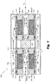
- FIG. 1 an illustrative view of an embodiment of a modular fiber membrane degassing system in accordance with the disclosure is shown in Fig. 1 and is designated generally by reference character 100.
- FIG. 2 Other embodiments of systems in accordance with the disclosure, or aspects thereof, are provided in Fig. 2 as will be described.
- the systems and methods described herein can be used provide modular degassing systems (e.g., for aircraft fuel deoxygenation systems), for example.
- the modular design allows a standardized fiber bundle to be used in multiple applications, where the number of bundles is selected based on application and need.
- a modular fiber membrane degassing system 100 includes an outer housing 102 and a system flow path 108 defined within the interior of outer housing 102.
- Outer housing 102 is shown as a generally hollow cylindrical outer housing 102, but could have a variety of suitable shapes.
- the system 100 is shown with an inlet 107 and an outlet 109 and a fiber bundle cartridge 101 positioned between inlet 107 and outlet 109.
- the fiber bundle 103 can include a single fiber wrapped many times, or a plurality of fibers.
- a longitudinal axis A is defined between inlet 107 and outlet 109 of the system flow path 108.
- the outer housing 102 is radially outward from the fiber bundle cartridge 101 and system flow path 108.
- cartridge 101 includes inner sleeves 106a and 106b, having generally hollow cylindrical shapes and each including a plurality of perforations 105a and 105b, respectively.
- Cartridge 101 includes an outer sleeve 104, which also has a generally hollow cylindrical shape, defining one or more outer sleeve perforations 120a and 120b.
- Cartridge 101 includes fiber bundles 103a and 103b each positioned radially outward from respective inner sleeves 106a and 106b.
- Annular epoxy layers 116 are positioned axially on either side of each fiber bundle 103a and 103b. For epoxy layers 116 that are adjacent to an epoxy layer around another fiber bundle, a vacuum area 117 is positioned between the adjacent annular epoxy layers 116.
- Annular seals 110 are positioned between the epoxy layers 116 and their respective abutting inner and outer sleeves 106a, 106b, and 104.
- fiber bundle 103b is sometimes referred to as additional fiber bundle 103b throughout this description.
- Additional fiber bundle 103b is downstream from inner sleeve 106a and fiber bundle 103a along system flow path 108.
- Inner sleeve 106a, fiber bundle 103a, additional inner sleeve 106b and additional fiber bundle 106b are positioned radially inward from outer sleeve 104.
- Each fiber bundle 103a and 103b defines an annular shape defining a central bundle axis, which, in the embodiment of Fig. 1 , aligns with longitudinal axis A of system 100 and cartridge 101. While the annular shape of each fiber bundle 103a and 103b is shown by fibers wrapped circumferentially (in a generally circular or helical manner) about longitudinal axis A, each fiber bundle can be formed by longitudinally extending fibers, as shown in Fig. 2 .
- Cartridge 201 is the same as cartridge 101 except that each fiber 205 extends substantially parallel to longitudinal axis A between epoxy 216 and would be positioned about longitudinal axis A in conjunction with other fibers to form a fiber bundle 203 in an annular shape.
- Cartridge 201 includes annular seals 210 and can similarly be separated from another cartridge by metal barrier, e.g. metal barrier 114.
- Cartridge 201 can include a sleeve, similar to sleeve 104, and can be used within the outer housing 102 of system 100, similar to how cartridge 101 is arranged within system 100.
- Fiber bundle 203 can also be made from a single fiber 205 that is axially extending with turns at the axial ends proximate to the epoxy 216.
- a "fiber" can be a single strand of material or a series of strands of material wound together to form a single fiber, like fiber 205 (or like one of the fibers of bundle 101a/101b). The fiber can then be axially positioned, as shown in Fig. 2 , or wrapped in a circular/helical manner as shown in the fiber bundle of Fig. 1 .
- perforations 105a of inner sleeve 106a define a plurality of inlets into fiber bundle 103a.
- Perforations 105a face radially with respect to the central bundle axis, which is shown as longitudinal axis A in Fig. 1 , which acts to guide fluid flow radially through bundle 103a to outlets 120a of outer sleeve 104.
- the pressure drop across the bundle is reduced.
- the system inlet and outlet however, e.g. inlet and outlet 107 and 109, respectively, remain axially oriented for ease of installation.
- Outlets 120a of outer sleeve 104 face radially with respect to the central bundle axis.
- Perforations 105b of inner sleeve 106b define a plurality of outlets out of fiber bundle 103b.
- Perforations 105b face radially with respect to the central bundle axis, which acts to guide fluid flow from inlets 120b of outer sleeve 104 through to an interior cavity 122b of additional inner sleeve 106b.
- Cartridge 101 includes a metal barrier 114, e.g.
- annular seals 110 can be positioned between the metal barrier 114 and inner sleeves 106a and 106b.
- inner sleeves 106a and 106b and fiber bundles 103a and 103b are positioned radially inward from outer sleeve 104.
- Each cartridge 101 defines a cartridge flow path, which is the portion of system flow path 108 that is within the inner diameter of outer sleeve 104.
- System flow path 108 is at least partially defined within interior cavities 122a and 122b of inner sleeves 106a and 106b. At least a portion of the cartridge flow path is defined between an interior cavity 122a of inner sleeve 106a and an interior cavity 122b of additional inner sleeve 106b.
- Fiber bundle 103b is downstream from inner sleeve 106a and fiber bundle 103b along cartridge flow path 108. Additional fiber bundle 103b is upstream from additional inner sleeve 106b along cartridge flow path 108, meaning that fluid flow goes from fiber bundle 103b and travels radially inward to interior cavity 122b.
- the one or more outer sleeve 104 perforations includes two sets of perforations, wherein a first of the two sets of perforations, denoted by perforations 120a is at a common axial position relative to longitudinal axis A with fiber bundle 103a.
- a second of the two sets of perforations, denoted by perforations 120b, is at a second common axial position relative to longitudinal axis A with additional fiber bundle 103b.
- the second of the two sets of perforations 120b is downstream from the first of the two sets 120a. This allows fluid to flow from interior cavity 122a, radially outward through fiber bundle 103a and through perforations 120a.
- cartridge 101 can have a single fiber bundle 103a and single inner sleeve 106a, or multiple fiber bundles 103a and inner sleeves 106a and 106b, as shown.
- a single outer sleeve 104 could have three fiber bundles and three inner sleeves associated therewith.
- outer sleeve 104 inner sleeves 106a and 106b, and metal barrier 114 maintain vacuum area 117 through multiple axial fiber bundles 103a and 103b.
- similar vacuum cavities 117 are maintained between each bundle using the architecture of the inner and outer sleeves with a spacer, e.g. barrier 114, and seals, e.g. seals 110.
Landscapes
- Chemical & Material Sciences (AREA)
- Chemical Kinetics & Catalysis (AREA)
- Separation Using Semi-Permeable Membranes (AREA)
- Degasification And Air Bubble Elimination (AREA)
Abstract
Description
- The present disclosure relates to fluid degassing systems, more specifically to fiber degassing systems (e.g., for fuel degassing such as deoxygenation).
- Gas turbine engines operate more efficiently at higher system and fuel temperatures. As a result, increased thermal loads and decreased fuel flows anticipated for next generation aircraft will cause higher temperature fuel considering fuel is used as a heat sink. However, when exposed to higher temperatures hydrocarbon fuels tend to form carbonaceous deposits (coke) on fuel wetted components due to the presence of dissolved oxygen, hence fuel stabilization will be required in order to meet performance, engine life and operability targets. Coke is a solid residue created when fuels see oxidative and thermal breakdown at high temperature. Reduction or removal of oxygen in the fuel significantly decreases coke at high fuel temperatures, which allows gas turbines to operate at higher temperatures. One way to remove dissolved oxygen from fuel (the root cause of deposits) is by means of a membrane-based fuel deoxygenator.
- Such conventional methods and systems have generally been considered satisfactory for their intended purpose. However, there is still a need in the art for improved liquid degassing systems. The present disclosure provides a solution for this need.
- A fiber bundle cartridge for a fiber membrane degassing system includes an inner sleeve including one or more perforations and a fiber bundle positioned radially outward from the inner sleeve. The fiber bundle has an annular shape that defines a central bundle axis. The perforations of the inner sleeve define at least one of a plurality of inlets or a plurality of outlets facing radially with respect to the central bundle axis.
- In some embodiments, the cartridge includes an outer sleeve that defines one or more outer sleeve perforations. The outer sleeve can be positioned radially outward from the fiber bundle. The outer sleeve perforations can define at least one of a plurality of inlets or a plurality of outlets facing radially with respect to the central bundle axis. The fiber bundle can include at least one fiber extending parallel to the central bundle axis.
- The cartridge can include an additional inner sleeve and an additional fiber bundle positioned radially outward from the additional inner sleeve. The additional fiber bundle can have an annular shape defining central bundle axis. The perforations of the additional inner sleeve can define at least one of a plurality of inlets or a plurality of outlets facing radially with respect to the central bundle axis of the additional fiber bundle. The cartridge can include a metal barrier positioned between the inner sleeve and the additional inner sleeve.
- The additional inner sleeve and the additional fiber bundle can be positioned radially inward from the outer sleeve. The cartridge can define a cartridge flow path defined between an interior cavity of the inner sleeve an interior cavity of the additional inner sleeve. The additional fiber bundle can be downstream from the inner sleeve and the fiber bundle along the cartridge flow path. The additional fiber bundle can be upstream from the additional inner sleeve along the cartridge flow path.
- The one or more outer sleeve perforations can include two sets of perforations. A first of the two sets of perforations can be at a common axial position with the fiber bundle. A second of the two sets of perforations can be at a second common axial position with the additional fiber bundle. The second of the two sets of perforations can be downstream from the first of the two sets.
- In accordance with another aspect, a fiber membrane degassing system includes a housing defining a cylindrical volume having at least one inlet and at least one outlet. The system includes at least one fiber positioned within the cylindrical volume such that fluid flowing through the cylindrical volume from the at least one inlet to the at least one outlet flows perpendicular to a longitudinal dimension of the at least one fiber.
- In some embodiments, the housing is an outer housing radially outward from the at least one fiber. The at least one inlet and the at least one outlet can be axially facing. The outer housing can define a system flow path between the axially facing inlet and the axially facing outlet. The at least one fiber can be positioned within a fiber bundle cartridge positioned within the cylindrical volume. The cartridge can include an inner sleeve including one or more perforations. The at least one fiber can form a fiber bundle having an annular shape defining a central bundle axis. The perforations of the inner sleeve can define at least one of a plurality of inlets or a plurality of outlets facing radially with respect to the central bundle axis.
- The cartridge can include an outer sleeve defining one or more outer sleeve perforations. The outer sleeve can be positioned radially outward from the fiber bundle. The outer sleeve perforations can define at least one of a plurality of inlets or a plurality of outlets facing radially with respect to the central bundle axis.
- The cartridge can include an additional inner sleeve and an additional fiber bundle positioned radially outward from the additional inner sleeve. The additional fiber bundle can have an annular shape defining central bundle axis. The perforations of the additional inner sleeve can be similar to those of the inner sleeve described above. The additional fiber bundle can be downstream from the inner sleeve and the fiber bundle along a system flow path defined between the inlet and the outlet of the housing. The cartridge can include a metal barrier positioned between the inner sleeve and the additional inner sleeve. The cartridge can include an outer sleeve defining one or more outer sleeve perforations. The inner sleeve, the fiber bundle, the additional inner sleeve and the additional fiber bundle can be positioned radially inward from the outer sleeve. A longitudinal axis can be defined between the inlet and the outlet of the housing. The one or more outer sleeve perforations can include two sets of perforations. A first of the two sets of perforations can be at a common axial position relative to the longitudinal axis with the fiber bundle. A second of the two sets of perforations can be at a second common axial position relative to the longitudinal axis with the additional fiber bundle.
- In accordance with another aspect, a method of degassing a liquid includes directing a liquid volume through a fiber bundle in a direction radial to a longitudinally extending bundle axis.
- These and other features of the systems and methods of the subject disclosure will become more readily apparent to those skilled in the art from the following detailed description taken in conjunction with the drawings.
- So that those skilled in the art to which the subject disclosure appertains will readily understand how to make and use the devices and methods of the subject disclosure without undue experimentation, embodiments thereof will be described in detail herein below with reference to certain figures, wherein:
-
Fig. 1 is a schematic cross-sectional view of an embodiment of a modular fiber membrane degassing system constructed in accordance with the present disclosure, showing a fiber bundle cartridge; and -
Fig. 2 is a schematic cross-sectional view of a portion of another embodiment of a modular fiber membrane degassing system constructed in accordance with the present disclosure, showing a portion of a fiber bundle cartridge having axially extending fibers. - Reference will now be made to the drawings wherein like reference numerals identify similar structural features or aspects of the subject disclosure. For purposes of explanation and illustration, and not limitation, an illustrative view of an embodiment of a modular fiber membrane degassing system in accordance with the disclosure is shown in
Fig. 1 and is designated generally byreference character 100. Other embodiments of systems in accordance with the disclosure, or aspects thereof, are provided inFig. 2 as will be described. The systems and methods described herein can be used provide modular degassing systems (e.g., for aircraft fuel deoxygenation systems), for example. The modular design allows a standardized fiber bundle to be used in multiple applications, where the number of bundles is selected based on application and need. - As shown in
Fig. 1 , a modular fibermembrane degassing system 100 includes anouter housing 102 and asystem flow path 108 defined within the interior ofouter housing 102.Outer housing 102 is shown as a generally hollow cylindricalouter housing 102, but could have a variety of suitable shapes. Thesystem 100 is shown with aninlet 107 and anoutlet 109 and afiber bundle cartridge 101 positioned betweeninlet 107 andoutlet 109. The fiber bundle 103 can include a single fiber wrapped many times, or a plurality of fibers. A longitudinal axis A is defined betweeninlet 107 andoutlet 109 of thesystem flow path 108. Theouter housing 102 is radially outward from thefiber bundle cartridge 101 and system flowpath 108. - With continued reference to
Fig. 1 ,cartridge 101 includesinner sleeves perforations Cartridge 101 includes anouter sleeve 104, which also has a generally hollow cylindrical shape, defining one or moreouter sleeve perforations Cartridge 101 includesfiber bundles inner sleeves fiber bundle epoxy layers 116 that are adjacent to an epoxy layer around another fiber bundle, avacuum area 117 is positioned between the adjacent annular epoxy layers 116.Annular seals 110 are positioned between theepoxy layers 116 and their respective abutting inner andouter sleeves fiber bundle 103b is sometimes referred to asadditional fiber bundle 103b throughout this description.Additional fiber bundle 103b is downstream frominner sleeve 106a andfiber bundle 103a alongsystem flow path 108.Inner sleeve 106a,fiber bundle 103a, additionalinner sleeve 106b andadditional fiber bundle 106b are positioned radially inward fromouter sleeve 104. - Each
fiber bundle Fig. 1 , aligns with longitudinal axis A ofsystem 100 andcartridge 101. While the annular shape of eachfiber bundle Fig. 2 . - With reference now to
Fig. 2 , a portion of another embodiment of acartridge 201 is shown.Cartridge 201 is the same ascartridge 101 except that eachfiber 205 extends substantially parallel to longitudinal axis A betweenepoxy 216 and would be positioned about longitudinal axis A in conjunction with other fibers to form afiber bundle 203 in an annular shape.Cartridge 201 includesannular seals 210 and can similarly be separated from another cartridge by metal barrier,e.g. metal barrier 114.Cartridge 201 can include a sleeve, similar tosleeve 104, and can be used within theouter housing 102 ofsystem 100, similar to howcartridge 101 is arranged withinsystem 100.Fiber bundle 203 can also be made from asingle fiber 205 that is axially extending with turns at the axial ends proximate to theepoxy 216. Those skilled in the art will readily appreciate that a "fiber" can be a single strand of material or a series of strands of material wound together to form a single fiber, like fiber 205 (or like one of the fibers of bundle 101a/101b). The fiber can then be axially positioned, as shown inFig. 2 , or wrapped in a circular/helical manner as shown in the fiber bundle ofFig. 1 . - As shown in
Fig. 1 ,perforations 105a ofinner sleeve 106a define a plurality of inlets intofiber bundle 103a.Perforations 105a face radially with respect to the central bundle axis, which is shown as longitudinal axis A inFig. 1 , which acts to guide fluid flow radially throughbundle 103a tooutlets 120a ofouter sleeve 104. By directing fluid flow radially, rather than axially as with traditional systems, the pressure drop across the bundle is reduced. The system inlet and outlet, however, e.g. inlet andoutlet Outlets 120a ofouter sleeve 104 face radially with respect to the central bundle axis.Perforations 105b ofinner sleeve 106b define a plurality of outlets out offiber bundle 103b.Perforations 105b face radially with respect to the central bundle axis, which acts to guide fluid flow frominlets 120b ofouter sleeve 104 through to aninterior cavity 122b of additionalinner sleeve 106b. The forced radially flow paths betweeninner sleeves outer sleeve 104 keeps fuel in a given one of thefiber bundles Inlets 120b ofouter sleeve 104 face radially with respect to the central bundle axis.Cartridge 101 includes ametal barrier 114, e.g. aspacer 114, positioned axially betweeninner sleeve 106a and additionalinner sleeve 106b such that flow entering throughinner sleeve 106a and exiting through 106b must pass throughfiber bundle 103a, alongflow path 108, and back throughfiber bundle 103b.Annular seals 110 can be positioned between themetal barrier 114 andinner sleeves - With continued reference to
Fig. 1 ,inner sleeves fiber bundles outer sleeve 104. Eachcartridge 101 defines a cartridge flow path, which is the portion ofsystem flow path 108 that is within the inner diameter ofouter sleeve 104.System flow path 108 is at least partially defined withininterior cavities inner sleeves interior cavity 122a ofinner sleeve 106a and aninterior cavity 122b of additionalinner sleeve 106b.Fiber bundle 103b is downstream frominner sleeve 106a andfiber bundle 103b alongcartridge flow path 108.Additional fiber bundle 103b is upstream from additionalinner sleeve 106b alongcartridge flow path 108, meaning that fluid flow goes fromfiber bundle 103b and travels radially inward tointerior cavity 122b. - As shown in
Fig. 1 , the one or moreouter sleeve 104 perforations includes two sets of perforations, wherein a first of the two sets of perforations, denoted byperforations 120a is at a common axial position relative to longitudinal axis A withfiber bundle 103a. A second of the two sets of perforations, denoted byperforations 120b, is at a second common axial position relative to longitudinal axis A withadditional fiber bundle 103b. The second of the two sets ofperforations 120b is downstream from the first of the twosets 120a. This allows fluid to flow frominterior cavity 122a, radially outward throughfiber bundle 103a and throughperforations 120a. The system flowpath 108 then travels axially within the generally annular space betweenouter housing 102 andouter sleeve 104, and back radially inward throughperforations 120b throughadditional fiber bundle 103b and throughoutlets 105b. Those skilled in the art will readily appreciate that a number ofcartridges 101 could be used insystem 100. For example, there could be another cartridge positioned upstream or downstream fromcartridge 101. Moreover,cartridge 101 can have asingle fiber bundle 103a and singleinner sleeve 106a, ormultiple fiber bundles 103a andinner sleeves outer sleeve 104 could have three fiber bundles and three inner sleeves associated therewith. The use ofouter sleeve 104,inner sleeves metal barrier 114 maintainvacuum area 117 through multipleaxial fiber bundles similar vacuum cavities 117 are maintained between each bundle using the architecture of the inner and outer sleeves with a spacer,e.g. barrier 114, and seals, e.g. seals 110. - The methods and systems of the present disclosure, as described above and shown in the drawings, provide for degassing systems with superior properties including ease of manufacturability, installation, and/or replacement. While the apparatus and methods of the subject disclosure have been shown and described with reference to embodiments, those skilled in the art will readily appreciate that changes and/or modifications may be made thereto without departing from the spirit and scope of the subject disclosure.
Claims (15)
- A fiber bundle cartridge (101) for a fiber membrane degassing system,
an inner sleeve (106a) including one or more perforations (105a); and
a fiber bundle (103a, 103b) positioned radially outward from the inner sleeve (106a), the fiber bundle having an annular shape defining a central bundle axis, wherein the perforations of the inner sleeve define at least one of a plurality of inlets or a plurality of outlets facing radially with respect to the central bundle axis. - The fiber bundle cartridge as recited in claim 1, further comprising an outer sleeve defining one or more outer sleeve perforations, wherein the outer sleeve is positioned radially outward from the fiber bundle, wherein the outer sleeve perforations define at least one of a plurality of inlets or a plurality of outlets facing radially with respect to the central bundle axis.
- The fiber bundle cartridge as recited in claim 1 or 2, wherein the fiber bundle includes at least one fiber extending parallel to the central bundle axis.
- The fiber bundle cartridge as recited in any preceding claim, further comprising an additional inner sleeve and an additional fiber bundle positioned radially outward from the additional inner sleeve, wherein the additional fiber bundle has an annular shape defining central bundle axis, wherein the perforations of the additional inner sleeve define at least one of a plurality of inlets or a plurality of outlets facing radially with respect to the central bundle axis of the additional fiber bundle.
- The fiber bundle cartridge as recited in claim 4, further comprising a metal barrier positioned between the inner sleeve and the additional inner sleeve, or
wherein the cartridge includes an outer sleeve defining one or more outer sleeve perforations, wherein the additional inner sleeve and the additional fiber bundle are positioned radially inward from the outer sleeve. - The fiber bundle cartridge as recited in claim 4, further comprising a cartridge flow path defined between an interior cavity of the inner sleeve an interior cavity of the additional inner sleeve, optionally
wherein the additional fiber bundle is downstream from the inner sleeve and the fiber bundle along the cartridge flow path, or
wherein the additional fiber bundle is upstream from the additional inner sleeve along the cartridge flow path. - The fiber bundle cartridge as recited in claim 4, wherein the one or more outer sleeve perforations includes two sets of perforations, wherein a first of the two sets of perforations is at a common axial position with the fiber bundle, and wherein a second of the two sets of perforations is at a second common axial position with the additional fiber bundle, wherein the second of the two sets of perforations is downstream from the first of the two sets.
- A fiber membrane degassing system, comprising:a housing defining a cylindrical volume having at least one inlet and at least one outlet; andat least one fiber positioned within the cylindrical volume such that fluid flowing through the cylindrical volume from the at least one inlet to the at least one outlet flows perpendicular to a longitudinal dimension of the at least one fiber.
- The system as recited in claim 8, wherein the housing is an outer housing radially outward from the at least one fiber, wherein the at least one inlet and the at least one outlet are axially facing, and wherein the outer housing defines a system flow path between the axially facing inlet and the axially facing outlet.
- The system as recited in claim 8 or 9, wherein the at least one fiber is positioned within a fiber bundle cartridge positioned within the cylindrical volume, wherein the cartridge includes an inner sleeve including one or more perforations, wherein the at least one fiber forms a fiber bundle having an annular shape defining a central bundle axis, wherein the perforations of the inner sleeve define at least one of a plurality of inlets or a plurality of outlets facing radially with respect to the central bundle axis.
- The system as recited in claim 10, wherein the cartridge includes an outer sleeve defining one or more outer sleeve perforations, wherein the outer sleeve is positioned radially outward from the fiber bundle, wherein the outer sleeve perforations define at least one of a plurality of inlets or a plurality of outlets facing radially with respect to the central bundle axis.
- The system as recited in claim 10, wherein the cartridge includes an additional inner sleeve and an additional fiber bundle positioned radially outward from the additional inner sleeve, wherein the additional fiber bundle has an annular shape defining central bundle axis, wherein the perforations of the additional inner sleeve define at least one of a plurality of inlets or a plurality of outlets facing radially with respect to the central bundle axis of the additional fiber bundle.
- The system as recited in claim 12, wherein the additional fiber bundle is downstream from the inner sleeve and the fiber bundle along a system flow path defined between the inlet and the outlet of the housing, or
wherein the cartridge includes a metal barrier positioned between the inner sleeve and the additional inner sleeve. - The system as recited in claim 12 or 13, wherein the cartridge includes an outer sleeve defining one or more outer sleeve perforations, wherein the inner sleeve, the fiber bundle, the additional inner sleeve and the additional fiber bundle are positioned radially inward from the outer sleeve, optionally wherein a longitudinal axis is defined between the inlet and the outlet of the housing, wherein the one or more outer sleeve perforations includes two sets of perforations, wherein a first of the two sets of perforations is at a common axial position relative to the longitudinal axis with the fiber bundle, and wherein a second of the two sets of perforations is at a second common axial position relative to the longitudinal axis with the additional fiber bundle.
- A method of degassing a liquid, the method comprising:
directing a liquid volume through a fiber bundle in a direction radial to a longitudinally extending bundle axis.
Applications Claiming Priority (1)
| Application Number | Priority Date | Filing Date | Title |
|---|---|---|---|
| US16/430,072 US11331629B2 (en) | 2019-06-03 | 2019-06-03 | Modular liquid degassing systems |
Publications (2)
| Publication Number | Publication Date |
|---|---|
| EP3747524A1 true EP3747524A1 (en) | 2020-12-09 |
| EP3747524B1 EP3747524B1 (en) | 2024-06-26 |
Family
ID=68655340
Family Applications (1)
| Application Number | Title | Priority Date | Filing Date |
|---|---|---|---|
| EP19211156.5A Active EP3747524B1 (en) | 2019-06-03 | 2019-11-25 | Modular liquid degassing systems |
Country Status (2)
| Country | Link |
|---|---|
| US (1) | US11331629B2 (en) |
| EP (1) | EP3747524B1 (en) |
Citations (2)
| Publication number | Priority date | Publication date | Assignee | Title |
|---|---|---|---|---|
| US20030192820A1 (en) * | 2001-06-21 | 2003-10-16 | Kwantai Cho | Hollow fiber membrane contactor |
| EP3456405A1 (en) * | 2016-05-11 | 2019-03-20 | Mitsubishi Chemical Cleansui Corporation | Hollow fiber membrane module |
Family Cites Families (12)
| Publication number | Priority date | Publication date | Assignee | Title |
|---|---|---|---|---|
| TW408161B (en) * | 1997-04-30 | 2000-10-11 | Mitsubishi Rayon Co | Ink degassing hollow film, ink degassing method, ink degassing apparatus |
| US5938922A (en) * | 1997-08-19 | 1999-08-17 | Celgard Llc | Contactor for degassing liquids |
| US6149817A (en) * | 1999-03-08 | 2000-11-21 | Celgard Inc. | Shell-less hollow fiber membrane fluid contactor |
| US8293107B1 (en) | 2005-10-19 | 2012-10-23 | The United States Of America As Represented By The Secretary Of The Air Force | Fibers with axial capillary slit that enhances adsorption, absorption and separation |
| US8449659B2 (en) * | 2010-09-28 | 2013-05-28 | Celgard Llc | Liquid degassing membrane contactors, components, systems and related methods |
| US20190022558A1 (en) | 2017-07-24 | 2019-01-24 | Hamilton Sundstrand Corporation | Fuel tank de-oxygenation system |
| US20190022557A1 (en) | 2017-07-24 | 2019-01-24 | Hamilton Sundstrand Corporation | Fuel tank de-oxygenation system |
| US10758844B2 (en) | 2017-07-25 | 2020-09-01 | Hamilton Sundstrand Corporation | Fluid degassing devices having selected profiles |
| US20190054423A1 (en) | 2017-08-18 | 2019-02-21 | Hamilton Sundstrand Corporation | High temperature and pressure liquid degassing systems |
| US10576397B2 (en) | 2017-08-22 | 2020-03-03 | Hamilton Sundstrand Corporation | Hollow-fiber membrane for fuel degassing |
| US10456722B2 (en) | 2017-08-25 | 2019-10-29 | Hamilton Sundstrand Corporation | Integrated oxygen removal unit and fuel filter |
| WO2020132262A1 (en) * | 2018-12-22 | 2020-06-25 | Advanced Liquide Advanced Technologies U.S. LLC | A method of separating a gas mixture comprising first and second gases using a gas separation membrane module having a plurality of hollow fiber membrane elements |
-
2019
- 2019-06-03 US US16/430,072 patent/US11331629B2/en active Active
- 2019-11-25 EP EP19211156.5A patent/EP3747524B1/en active Active
Patent Citations (2)
| Publication number | Priority date | Publication date | Assignee | Title |
|---|---|---|---|---|
| US20030192820A1 (en) * | 2001-06-21 | 2003-10-16 | Kwantai Cho | Hollow fiber membrane contactor |
| EP3456405A1 (en) * | 2016-05-11 | 2019-03-20 | Mitsubishi Chemical Cleansui Corporation | Hollow fiber membrane module |
Also Published As
| Publication number | Publication date |
|---|---|
| US11331629B2 (en) | 2022-05-17 |
| US20200376436A1 (en) | 2020-12-03 |
| EP3747524B1 (en) | 2024-06-26 |
Similar Documents
| Publication | Publication Date | Title |
|---|---|---|
| EP3671039B1 (en) | Multipoint fuel injection system with heat shield | |
| EP2927426B1 (en) | Cooling system with a bearing compartment bypass and corresponding method | |
| US9598974B2 (en) | Active turbine or compressor tip clearance control | |
| EP2966395B1 (en) | Method and system for radial tubular heat exchangers | |
| EP3026384B1 (en) | Heat exchanger | |
| EP3598003B1 (en) | Multipoint injection system | |
| EP3267024A1 (en) | Rocket engine | |
| US11585275B2 (en) | Internal manifold for multipoint injection | |
| US11994297B2 (en) | Fluid nozzles with heat shielding | |
| US20210278083A1 (en) | Fuel manifolds | |
| EP2971820B1 (en) | Rolling element bearing configured with a channel and one or more fluid passages | |
| EP3770502B1 (en) | Multipoint fuel injection system and related manufacturing method | |
| EP3747524B1 (en) | Modular liquid degassing systems | |
| US10233757B2 (en) | Rotor for a thermal turbomachine | |
| EP4197621B1 (en) | Diffuser nozzle for a gas turbine engine | |
| EP3561384B1 (en) | Oxygen removal unit with tortuous path | |
| EP3450724B1 (en) | Integrated oxygen removal unit and fuel filter | |
| US8105032B2 (en) | Systems and methods for internally cooling a wheel of a steam turbine | |
| EP3809044B1 (en) | Gasturbine engine with a fuel manifold | |
| US20190030461A1 (en) | Fluid degassing systems | |
| US11454395B2 (en) | Thermal resistant air caps | |
| JP6871214B2 (en) | Turbine equipment and combustor nozzle |
Legal Events
| Date | Code | Title | Description |
|---|---|---|---|
| PUAI | Public reference made under article 153(3) epc to a published international application that has entered the european phase |
Free format text: ORIGINAL CODE: 0009012 |
|
| STAA | Information on the status of an ep patent application or granted ep patent |
Free format text: STATUS: THE APPLICATION HAS BEEN PUBLISHED |
|
| AK | Designated contracting states |
Kind code of ref document: A1 Designated state(s): AL AT BE BG CH CY CZ DE DK EE ES FI FR GB GR HR HU IE IS IT LI LT LU LV MC MK MT NL NO PL PT RO RS SE SI SK SM TR |
|
| AX | Request for extension of the european patent |
Extension state: BA ME |
|
| STAA | Information on the status of an ep patent application or granted ep patent |
Free format text: STATUS: REQUEST FOR EXAMINATION WAS MADE |
|
| 17P | Request for examination filed |
Effective date: 20210609 |
|
| RBV | Designated contracting states (corrected) |
Designated state(s): AL AT BE BG CH CY CZ DE DK EE ES FI FR GB GR HR HU IE IS IT LI LT LU LV MC MK MT NL NO PL PT RO RS SE SI SK SM TR |
|
| STAA | Information on the status of an ep patent application or granted ep patent |
Free format text: STATUS: EXAMINATION IS IN PROGRESS |
|
| 17Q | First examination report despatched |
Effective date: 20210906 |
|
| REG | Reference to a national code |
Ref country code: DE Ref legal event code: R079 Free format text: PREVIOUS MAIN CLASS: B01D0019000000 Ipc: B01D0063040000 Ref country code: DE Ref legal event code: R079 Ref document number: 602019054124 Country of ref document: DE Free format text: PREVIOUS MAIN CLASS: B01D0019000000 Ipc: B01D0063040000 |
|
| GRAP | Despatch of communication of intention to grant a patent |
Free format text: ORIGINAL CODE: EPIDOSNIGR1 |
|
| STAA | Information on the status of an ep patent application or granted ep patent |
Free format text: STATUS: GRANT OF PATENT IS INTENDED |
|
| RIC1 | Information provided on ipc code assigned before grant |
Ipc: B01D 19/00 20060101ALI20231221BHEP Ipc: B01D 63/04 20060101AFI20231221BHEP |
|
| INTG | Intention to grant announced |
Effective date: 20240122 |
|
| GRAS | Grant fee paid |
Free format text: ORIGINAL CODE: EPIDOSNIGR3 |
|
| GRAA | (expected) grant |
Free format text: ORIGINAL CODE: 0009210 |
|
| STAA | Information on the status of an ep patent application or granted ep patent |
Free format text: STATUS: THE PATENT HAS BEEN GRANTED |
|
| AK | Designated contracting states |
Kind code of ref document: B1 Designated state(s): AL AT BE BG CH CY CZ DE DK EE ES FI FR GB GR HR HU IE IS IT LI LT LU LV MC MK MT NL NO PL PT RO RS SE SI SK SM TR |
|
| REG | Reference to a national code |
Ref country code: GB Ref legal event code: FG4D |
|
| REG | Reference to a national code |
Ref country code: CH Ref legal event code: EP |
|
| REG | Reference to a national code |
Ref country code: DE Ref legal event code: R096 Ref document number: 602019054124 Country of ref document: DE |
|
| PG25 | Lapsed in a contracting state [announced via postgrant information from national office to epo] |
Ref country code: BG Free format text: LAPSE BECAUSE OF FAILURE TO SUBMIT A TRANSLATION OF THE DESCRIPTION OR TO PAY THE FEE WITHIN THE PRESCRIBED TIME-LIMIT Effective date: 20240626 |
|
| PG25 | Lapsed in a contracting state [announced via postgrant information from national office to epo] |
Ref country code: HR Free format text: LAPSE BECAUSE OF FAILURE TO SUBMIT A TRANSLATION OF THE DESCRIPTION OR TO PAY THE FEE WITHIN THE PRESCRIBED TIME-LIMIT Effective date: 20240626 Ref country code: FI Free format text: LAPSE BECAUSE OF FAILURE TO SUBMIT A TRANSLATION OF THE DESCRIPTION OR TO PAY THE FEE WITHIN THE PRESCRIBED TIME-LIMIT Effective date: 20240626 |
|
| REG | Reference to a national code |
Ref country code: LT Ref legal event code: MG9D |
|
| PG25 | Lapsed in a contracting state [announced via postgrant information from national office to epo] |
Ref country code: GR Free format text: LAPSE BECAUSE OF FAILURE TO SUBMIT A TRANSLATION OF THE DESCRIPTION OR TO PAY THE FEE WITHIN THE PRESCRIBED TIME-LIMIT Effective date: 20240927 |
|
| PG25 | Lapsed in a contracting state [announced via postgrant information from national office to epo] |
Ref country code: LV Free format text: LAPSE BECAUSE OF FAILURE TO SUBMIT A TRANSLATION OF THE DESCRIPTION OR TO PAY THE FEE WITHIN THE PRESCRIBED TIME-LIMIT Effective date: 20240626 |
|
| REG | Reference to a national code |
Ref country code: NL Ref legal event code: MP Effective date: 20240626 |
|
| PG25 | Lapsed in a contracting state [announced via postgrant information from national office to epo] |
Ref country code: NO Free format text: LAPSE BECAUSE OF FAILURE TO SUBMIT A TRANSLATION OF THE DESCRIPTION OR TO PAY THE FEE WITHIN THE PRESCRIBED TIME-LIMIT Effective date: 20240926 Ref country code: LV Free format text: LAPSE BECAUSE OF FAILURE TO SUBMIT A TRANSLATION OF THE DESCRIPTION OR TO PAY THE FEE WITHIN THE PRESCRIBED TIME-LIMIT Effective date: 20240626 Ref country code: HR Free format text: LAPSE BECAUSE OF FAILURE TO SUBMIT A TRANSLATION OF THE DESCRIPTION OR TO PAY THE FEE WITHIN THE PRESCRIBED TIME-LIMIT Effective date: 20240626 Ref country code: GR Free format text: LAPSE BECAUSE OF FAILURE TO SUBMIT A TRANSLATION OF THE DESCRIPTION OR TO PAY THE FEE WITHIN THE PRESCRIBED TIME-LIMIT Effective date: 20240927 Ref country code: FI Free format text: LAPSE BECAUSE OF FAILURE TO SUBMIT A TRANSLATION OF THE DESCRIPTION OR TO PAY THE FEE WITHIN THE PRESCRIBED TIME-LIMIT Effective date: 20240626 Ref country code: BG Free format text: LAPSE BECAUSE OF FAILURE TO SUBMIT A TRANSLATION OF THE DESCRIPTION OR TO PAY THE FEE WITHIN THE PRESCRIBED TIME-LIMIT Effective date: 20240626 Ref country code: RS Free format text: LAPSE BECAUSE OF FAILURE TO SUBMIT A TRANSLATION OF THE DESCRIPTION OR TO PAY THE FEE WITHIN THE PRESCRIBED TIME-LIMIT Effective date: 20240926 |
|
| PG25 | Lapsed in a contracting state [announced via postgrant information from national office to epo] |
Ref country code: NL Free format text: LAPSE BECAUSE OF FAILURE TO SUBMIT A TRANSLATION OF THE DESCRIPTION OR TO PAY THE FEE WITHIN THE PRESCRIBED TIME-LIMIT Effective date: 20240626 |
|
| REG | Reference to a national code |
Ref country code: AT Ref legal event code: MK05 Ref document number: 1697254 Country of ref document: AT Kind code of ref document: T Effective date: 20240626 |
|
| PG25 | Lapsed in a contracting state [announced via postgrant information from national office to epo] |
Ref country code: NL Free format text: LAPSE BECAUSE OF FAILURE TO SUBMIT A TRANSLATION OF THE DESCRIPTION OR TO PAY THE FEE WITHIN THE PRESCRIBED TIME-LIMIT Effective date: 20240626 |
|
| PG25 | Lapsed in a contracting state [announced via postgrant information from national office to epo] |
Ref country code: PT Free format text: LAPSE BECAUSE OF FAILURE TO SUBMIT A TRANSLATION OF THE DESCRIPTION OR TO PAY THE FEE WITHIN THE PRESCRIBED TIME-LIMIT Effective date: 20241028 |
|
| PG25 | Lapsed in a contracting state [announced via postgrant information from national office to epo] |
Ref country code: PT Free format text: LAPSE BECAUSE OF FAILURE TO SUBMIT A TRANSLATION OF THE DESCRIPTION OR TO PAY THE FEE WITHIN THE PRESCRIBED TIME-LIMIT Effective date: 20241028 |
|
| PG25 | Lapsed in a contracting state [announced via postgrant information from national office to epo] |
Ref country code: PL Free format text: LAPSE BECAUSE OF FAILURE TO SUBMIT A TRANSLATION OF THE DESCRIPTION OR TO PAY THE FEE WITHIN THE PRESCRIBED TIME-LIMIT Effective date: 20240626 |
|
| PG25 | Lapsed in a contracting state [announced via postgrant information from national office to epo] |
Ref country code: EE Free format text: LAPSE BECAUSE OF FAILURE TO SUBMIT A TRANSLATION OF THE DESCRIPTION OR TO PAY THE FEE WITHIN THE PRESCRIBED TIME-LIMIT Effective date: 20240626 |
|
| PG25 | Lapsed in a contracting state [announced via postgrant information from national office to epo] |
Ref country code: AT Free format text: LAPSE BECAUSE OF FAILURE TO SUBMIT A TRANSLATION OF THE DESCRIPTION OR TO PAY THE FEE WITHIN THE PRESCRIBED TIME-LIMIT Effective date: 20240626 Ref country code: IS Free format text: LAPSE BECAUSE OF FAILURE TO SUBMIT A TRANSLATION OF THE DESCRIPTION OR TO PAY THE FEE WITHIN THE PRESCRIBED TIME-LIMIT Effective date: 20241026 |
|
| PG25 | Lapsed in a contracting state [announced via postgrant information from national office to epo] |
Ref country code: CZ Free format text: LAPSE BECAUSE OF FAILURE TO SUBMIT A TRANSLATION OF THE DESCRIPTION OR TO PAY THE FEE WITHIN THE PRESCRIBED TIME-LIMIT Effective date: 20240626 |
|
| PG25 | Lapsed in a contracting state [announced via postgrant information from national office to epo] |
Ref country code: SK Free format text: LAPSE BECAUSE OF FAILURE TO SUBMIT A TRANSLATION OF THE DESCRIPTION OR TO PAY THE FEE WITHIN THE PRESCRIBED TIME-LIMIT Effective date: 20240626 Ref country code: RO Free format text: LAPSE BECAUSE OF FAILURE TO SUBMIT A TRANSLATION OF THE DESCRIPTION OR TO PAY THE FEE WITHIN THE PRESCRIBED TIME-LIMIT Effective date: 20240626 |
|
| PG25 | Lapsed in a contracting state [announced via postgrant information from national office to epo] |
Ref country code: SM Free format text: LAPSE BECAUSE OF FAILURE TO SUBMIT A TRANSLATION OF THE DESCRIPTION OR TO PAY THE FEE WITHIN THE PRESCRIBED TIME-LIMIT Effective date: 20240626 Ref country code: ES Free format text: LAPSE BECAUSE OF FAILURE TO SUBMIT A TRANSLATION OF THE DESCRIPTION OR TO PAY THE FEE WITHIN THE PRESCRIBED TIME-LIMIT Effective date: 20240626 |
|
| PG25 | Lapsed in a contracting state [announced via postgrant information from national office to epo] |
Ref country code: SM Free format text: LAPSE BECAUSE OF FAILURE TO SUBMIT A TRANSLATION OF THE DESCRIPTION OR TO PAY THE FEE WITHIN THE PRESCRIBED TIME-LIMIT Effective date: 20240626 Ref country code: SK Free format text: LAPSE BECAUSE OF FAILURE TO SUBMIT A TRANSLATION OF THE DESCRIPTION OR TO PAY THE FEE WITHIN THE PRESCRIBED TIME-LIMIT Effective date: 20240626 Ref country code: RO Free format text: LAPSE BECAUSE OF FAILURE TO SUBMIT A TRANSLATION OF THE DESCRIPTION OR TO PAY THE FEE WITHIN THE PRESCRIBED TIME-LIMIT Effective date: 20240626 Ref country code: PL Free format text: LAPSE BECAUSE OF FAILURE TO SUBMIT A TRANSLATION OF THE DESCRIPTION OR TO PAY THE FEE WITHIN THE PRESCRIBED TIME-LIMIT Effective date: 20240626 Ref country code: IS Free format text: LAPSE BECAUSE OF FAILURE TO SUBMIT A TRANSLATION OF THE DESCRIPTION OR TO PAY THE FEE WITHIN THE PRESCRIBED TIME-LIMIT Effective date: 20241026 Ref country code: ES Free format text: LAPSE BECAUSE OF FAILURE TO SUBMIT A TRANSLATION OF THE DESCRIPTION OR TO PAY THE FEE WITHIN THE PRESCRIBED TIME-LIMIT Effective date: 20240626 Ref country code: EE Free format text: LAPSE BECAUSE OF FAILURE TO SUBMIT A TRANSLATION OF THE DESCRIPTION OR TO PAY THE FEE WITHIN THE PRESCRIBED TIME-LIMIT Effective date: 20240626 Ref country code: CZ Free format text: LAPSE BECAUSE OF FAILURE TO SUBMIT A TRANSLATION OF THE DESCRIPTION OR TO PAY THE FEE WITHIN THE PRESCRIBED TIME-LIMIT Effective date: 20240626 Ref country code: AT Free format text: LAPSE BECAUSE OF FAILURE TO SUBMIT A TRANSLATION OF THE DESCRIPTION OR TO PAY THE FEE WITHIN THE PRESCRIBED TIME-LIMIT Effective date: 20240626 |
|
| PG25 | Lapsed in a contracting state [announced via postgrant information from national office to epo] |
Ref country code: IT Free format text: LAPSE BECAUSE OF FAILURE TO SUBMIT A TRANSLATION OF THE DESCRIPTION OR TO PAY THE FEE WITHIN THE PRESCRIBED TIME-LIMIT Effective date: 20240626 |
|
| REG | Reference to a national code |
Ref country code: DE Ref legal event code: R097 Ref document number: 602019054124 Country of ref document: DE |
|
| PG25 | Lapsed in a contracting state [announced via postgrant information from national office to epo] |
Ref country code: DK Free format text: LAPSE BECAUSE OF FAILURE TO SUBMIT A TRANSLATION OF THE DESCRIPTION OR TO PAY THE FEE WITHIN THE PRESCRIBED TIME-LIMIT Effective date: 20240626 |
|
| PLBE | No opposition filed within time limit |
Free format text: ORIGINAL CODE: 0009261 |
|
| STAA | Information on the status of an ep patent application or granted ep patent |
Free format text: STATUS: NO OPPOSITION FILED WITHIN TIME LIMIT |
|
| 26N | No opposition filed |
Effective date: 20250327 |
|
| REG | Reference to a national code |
Ref country code: CH Ref legal event code: PL |
|
| PG25 | Lapsed in a contracting state [announced via postgrant information from national office to epo] |
Ref country code: MC Free format text: LAPSE BECAUSE OF FAILURE TO SUBMIT A TRANSLATION OF THE DESCRIPTION OR TO PAY THE FEE WITHIN THE PRESCRIBED TIME-LIMIT Effective date: 20240626 |
|
| PG25 | Lapsed in a contracting state [announced via postgrant information from national office to epo] |
Ref country code: LU Free format text: LAPSE BECAUSE OF NON-PAYMENT OF DUE FEES Effective date: 20241125 |
|
| REG | Reference to a national code |
Ref country code: CH Ref legal event code: PL |
|
| PG25 | Lapsed in a contracting state [announced via postgrant information from national office to epo] |
Ref country code: CH Free format text: LAPSE BECAUSE OF NON-PAYMENT OF DUE FEES Effective date: 20241130 |
|
| REG | Reference to a national code |
Ref country code: BE Ref legal event code: MM Effective date: 20241130 |
|
| PG25 | Lapsed in a contracting state [announced via postgrant information from national office to epo] |
Ref country code: SE Free format text: LAPSE BECAUSE OF FAILURE TO SUBMIT A TRANSLATION OF THE DESCRIPTION OR TO PAY THE FEE WITHIN THE PRESCRIBED TIME-LIMIT Effective date: 20240626 |
|
| PG25 | Lapsed in a contracting state [announced via postgrant information from national office to epo] |
Ref country code: BE Free format text: LAPSE BECAUSE OF NON-PAYMENT OF DUE FEES Effective date: 20241130 |
|
| PG25 | Lapsed in a contracting state [announced via postgrant information from national office to epo] |
Ref country code: IE Free format text: LAPSE BECAUSE OF NON-PAYMENT OF DUE FEES Effective date: 20241125 |
|
| PGFP | Annual fee paid to national office [announced via postgrant information from national office to epo] |
Ref country code: DE Payment date: 20251022 Year of fee payment: 7 |
|
| PGFP | Annual fee paid to national office [announced via postgrant information from national office to epo] |
Ref country code: GB Payment date: 20251023 Year of fee payment: 7 |
|
| PGFP | Annual fee paid to national office [announced via postgrant information from national office to epo] |
Ref country code: FR Payment date: 20251022 Year of fee payment: 7 |
|
| PG25 | Lapsed in a contracting state [announced via postgrant information from national office to epo] |
Ref country code: HU Free format text: LAPSE BECAUSE OF FAILURE TO SUBMIT A TRANSLATION OF THE DESCRIPTION OR TO PAY THE FEE WITHIN THE PRESCRIBED TIME-LIMIT; INVALID AB INITIO Effective date: 20191125 |
|
| PG25 | Lapsed in a contracting state [announced via postgrant information from national office to epo] |
Ref country code: CY Free format text: LAPSE BECAUSE OF FAILURE TO SUBMIT A TRANSLATION OF THE DESCRIPTION OR TO PAY THE FEE WITHIN THE PRESCRIBED TIME-LIMIT; INVALID AB INITIO Effective date: 20191125 |